EP1861554B1 - Sound absorbent - Google Patents
Sound absorbent Download PDFInfo
- Publication number
- EP1861554B1 EP1861554B1 EP06716779.1A EP06716779A EP1861554B1 EP 1861554 B1 EP1861554 B1 EP 1861554B1 EP 06716779 A EP06716779 A EP 06716779A EP 1861554 B1 EP1861554 B1 EP 1861554B1
- Authority
- EP
- European Patent Office
- Prior art keywords
- slits
- sound
- sound absorbent
- panel element
- absorbent according
- Prior art date
- Legal status (The legal status is an assumption and is not a legal conclusion. Google has not performed a legal analysis and makes no representation as to the accuracy of the status listed.)
- Revoked
Links
Images
Classifications
-
- E—FIXED CONSTRUCTIONS
- E04—BUILDING
- E04B—GENERAL BUILDING CONSTRUCTIONS; WALLS, e.g. PARTITIONS; ROOFS; FLOORS; CEILINGS; INSULATION OR OTHER PROTECTION OF BUILDINGS
- E04B1/00—Constructions in general; Structures which are not restricted either to walls, e.g. partitions, or floors or ceilings or roofs
- E04B1/62—Insulation or other protection; Elements or use of specified material therefor
- E04B1/74—Heat, sound or noise insulation, absorption, or reflection; Other building methods affording favourable thermal or acoustical conditions, e.g. accumulating of heat within walls
- E04B1/82—Heat, sound or noise insulation, absorption, or reflection; Other building methods affording favourable thermal or acoustical conditions, e.g. accumulating of heat within walls specifically with respect to sound only
- E04B1/84—Sound-absorbing elements
- E04B1/86—Sound-absorbing elements slab-shaped
-
- E—FIXED CONSTRUCTIONS
- E04—BUILDING
- E04C—STRUCTURAL ELEMENTS; BUILDING MATERIALS
- E04C2/00—Building elements of relatively thin form for the construction of parts of buildings, e.g. sheet materials, slabs, or panels
- E04C2/02—Building elements of relatively thin form for the construction of parts of buildings, e.g. sheet materials, slabs, or panels characterised by specified materials
- E04C2/26—Building elements of relatively thin form for the construction of parts of buildings, e.g. sheet materials, slabs, or panels characterised by specified materials composed of materials covered by two or more of groups E04C2/04, E04C2/08, E04C2/10 or of materials covered by one of these groups with a material not specified in one of the groups
- E04C2/284—Building elements of relatively thin form for the construction of parts of buildings, e.g. sheet materials, slabs, or panels characterised by specified materials composed of materials covered by two or more of groups E04C2/04, E04C2/08, E04C2/10 or of materials covered by one of these groups with a material not specified in one of the groups at least one of the materials being insulating
-
- E—FIXED CONSTRUCTIONS
- E04—BUILDING
- E04F—FINISHING WORK ON BUILDINGS, e.g. STAIRS, FLOORS
- E04F13/00—Coverings or linings, e.g. for walls or ceilings
- E04F13/07—Coverings or linings, e.g. for walls or ceilings composed of covering or lining elements; Sub-structures therefor; Fastening means therefor
- E04F13/072—Coverings or linings, e.g. for walls or ceilings composed of covering or lining elements; Sub-structures therefor; Fastening means therefor composed of specially adapted, structured or shaped covering or lining elements
- E04F13/075—Coverings or linings, e.g. for walls or ceilings composed of covering or lining elements; Sub-structures therefor; Fastening means therefor composed of specially adapted, structured or shaped covering or lining elements for insulation or surface protection, e.g. against noise or impact
-
- G—PHYSICS
- G10—MUSICAL INSTRUMENTS; ACOUSTICS
- G10K—SOUND-PRODUCING DEVICES; METHODS OR DEVICES FOR PROTECTING AGAINST, OR FOR DAMPING, NOISE OR OTHER ACOUSTIC WAVES IN GENERAL; ACOUSTICS NOT OTHERWISE PROVIDED FOR
- G10K11/00—Methods or devices for transmitting, conducting or directing sound in general; Methods or devices for protecting against, or for damping, noise or other acoustic waves in general
- G10K11/16—Methods or devices for protecting against, or for damping, noise or other acoustic waves in general
-
- E—FIXED CONSTRUCTIONS
- E04—BUILDING
- E04B—GENERAL BUILDING CONSTRUCTIONS; WALLS, e.g. PARTITIONS; ROOFS; FLOORS; CEILINGS; INSULATION OR OTHER PROTECTION OF BUILDINGS
- E04B1/00—Constructions in general; Structures which are not restricted either to walls, e.g. partitions, or floors or ceilings or roofs
- E04B1/62—Insulation or other protection; Elements or use of specified material therefor
- E04B1/74—Heat, sound or noise insulation, absorption, or reflection; Other building methods affording favourable thermal or acoustical conditions, e.g. accumulating of heat within walls
- E04B1/82—Heat, sound or noise insulation, absorption, or reflection; Other building methods affording favourable thermal or acoustical conditions, e.g. accumulating of heat within walls specifically with respect to sound only
- E04B2001/8263—Mounting of acoustical elements on supporting structure, e.g. framework or wall surface
- E04B2001/8281—Flat elements mounted parallel to a supporting surface with an acoustically active air gap between the elements and the mounting surface
-
- E—FIXED CONSTRUCTIONS
- E04—BUILDING
- E04B—GENERAL BUILDING CONSTRUCTIONS; WALLS, e.g. PARTITIONS; ROOFS; FLOORS; CEILINGS; INSULATION OR OTHER PROTECTION OF BUILDINGS
- E04B1/00—Constructions in general; Structures which are not restricted either to walls, e.g. partitions, or floors or ceilings or roofs
- E04B1/62—Insulation or other protection; Elements or use of specified material therefor
- E04B1/74—Heat, sound or noise insulation, absorption, or reflection; Other building methods affording favourable thermal or acoustical conditions, e.g. accumulating of heat within walls
- E04B1/82—Heat, sound or noise insulation, absorption, or reflection; Other building methods affording favourable thermal or acoustical conditions, e.g. accumulating of heat within walls specifically with respect to sound only
- E04B1/84—Sound-absorbing elements
- E04B2001/8423—Tray or frame type panels or blocks, with or without acoustical filling
- E04B2001/8433—Tray or frame type panels or blocks, with or without acoustical filling with holes in their face
- E04B2001/8438—Slot shaped holes
-
- E—FIXED CONSTRUCTIONS
- E04—BUILDING
- E04B—GENERAL BUILDING CONSTRUCTIONS; WALLS, e.g. PARTITIONS; ROOFS; FLOORS; CEILINGS; INSULATION OR OTHER PROTECTION OF BUILDINGS
- E04B1/00—Constructions in general; Structures which are not restricted either to walls, e.g. partitions, or floors or ceilings or roofs
- E04B1/62—Insulation or other protection; Elements or use of specified material therefor
- E04B1/74—Heat, sound or noise insulation, absorption, or reflection; Other building methods affording favourable thermal or acoustical conditions, e.g. accumulating of heat within walls
- E04B1/82—Heat, sound or noise insulation, absorption, or reflection; Other building methods affording favourable thermal or acoustical conditions, e.g. accumulating of heat within walls specifically with respect to sound only
- E04B1/84—Sound-absorbing elements
- E04B2001/8457—Solid slabs or blocks
- E04B2001/8476—Solid slabs or blocks with acoustical cavities, with or without acoustical filling
- E04B2001/848—Solid slabs or blocks with acoustical cavities, with or without acoustical filling the cavities opening onto the face of the element
- E04B2001/8495—Solid slabs or blocks with acoustical cavities, with or without acoustical filling the cavities opening onto the face of the element the openings going through from one face to the other face of the element
-
- E—FIXED CONSTRUCTIONS
- E04—BUILDING
- E04F—FINISHING WORK ON BUILDINGS, e.g. STAIRS, FLOORS
- E04F2290/00—Specially adapted covering, lining or flooring elements not otherwise provided for
- E04F2290/04—Specially adapted covering, lining or flooring elements not otherwise provided for for insulation or surface protection, e.g. against noise, impact or fire
- E04F2290/041—Specially adapted covering, lining or flooring elements not otherwise provided for for insulation or surface protection, e.g. against noise, impact or fire against noise
Definitions
- the invention relates to a sound absorbent for absorption of acoustic waves, as stated in the preamble of claim 1.
- Fiber absorbents comprise porous panels of mineral fibres (rock and glass wool), which dampen sound as the sound waves penetrate into the panel, and the energy of the sound waves is reduced by viscous losses in the pores and absorbed by the fibres as heat.
- absorbents which are based on the Helmholz resonator principle.
- Such panels generally include slits or apertures, and require fibre fabric or porous fibre materials behind the panel to obtain satisfactory absorption.
- a fibre fabric is used, but this is often combined with thicker fibre mats to obtain better absorption.
- the fibre fabric is often integrated as a surface layer on the fibre mat.
- membrane absorbent Another type of absorbent is membrane absorbent.
- the most common type is thin panels of metal, such as steel or aluminium, or of plastic, which is mounted at a certain distance from a wall or ceiling.
- a special type is disclosed in patent publication US 5,719,359 .
- the sound is absorbed as the sound energy creates movement in a membrane, in the form of thin strips.
- the general problem with membrane absorbents is that the resistive component, which makes them function as an absorbent, is small, and moreover, is almost impossible to estimate. This is partially solved by arranging the strips against each other, yielding friction as they move as a result of the sound.
- Patent publication US 4,821,841 discloses a panel element for sound absorption, with a panel with slits arranged over a rear plate.
- the slits are approximately 1.6 to 19 mm wide, and the panel element is adapted to have fibre material arranged in the space between the panel with slits and the rear plate, to obtain the desired absorption.
- Another type of panel avoids these drawbacks by using friction by viscous airflow to dampen the sound waves.
- Such known panels comprise microperforations, i.e. holes through the panel of diameters less than 0.5 mm. These panels are not dependent on fibre materials.
- the panel is arranged with a distance from a rear surface, in such way that an air space is formed between the microperforated panel and the rear surface. As the sound waves hit the panel, the air in the perforations is forced back and forth due to the pressure differences resulting from the sound waves. This movement results in viscous friction, by which the energy in the sound waves is converted to heat, whereby the sound waves are dampened.
- Such a sound absorbing panel element is disclosed in patent publication WO 03001501 .
- This panel element is intended for sound isolation of car engines and the like, but can also be used as sound absorbing elements in buildings.
- the panel element consists of a panel with microperforations, arranged at a distance to a rear surface, with the perforated panel facing the sound source. This panel element avoids the disadvantages of fibre based sound absorbents, as described above.
- Microperforated panels and foils are in many cases produced by rolling a tool with many small spikes over the surface or the foil.
- Other methods, such as laser cutting and plastic moulding are used for thicker panels and for panels of other materials.
- WO 00/68039 A1 describes a sound-shielding element to prevent propogation of sound.
- the sound-shielding element exhibits a panel (1).
- Embodiments having elongate slits are also described.
- the object of the invention is to provide a new type of sound absorbent, which avoids the above-mentioned drawbacks of fibre based sound absorbents, and which simultaneously exhibits better absorption characteristics and is less costly to produce than many known sound absorbents based on microperforations. It is also an object of the invention to open new fields of use and to provide design-related advantages compared to known sound absorbents.
- a sound absorbent is obtained with a sound absorbent according to the invention, and comprises a panel element with slits there through, which panel element, when in use, is arranged at a distance from a rear surface, creating a space between the panel element and the rear surface.
- slits is meant slits with a minimum slit width less than 0.45 mm.
- the sound waves are dampened by friction of viscous flow. Due to pressure changes resulting from the sound waves, the air in the small slits is forced back and forth, and the energy in the sound waves is converted into heat due to the friction of the viscous flow. To obtain this vibration of air in the slits, the rear surface is at a distance from the panel element, so that the air pressure in the air between the panel element and the rear surface will fluctuate due to acoustic waves that impact the panel element and its slits.
- panel element herein means the outer part of the sound absorbent, which constitutes a wall or a shell or the like facing the surroundings in such a way that it is arranged between the surroundings and a rear space, which rear space is at least partially confined by the panel element and the mentioned rear surface.
- panel element it is not intended to limit the shape to a planar shaped plate.
- the sound absorbent's panel element can essentially be shaped to an arbitrary form, for instance a ball, a rod, or a more "organic" arbitrary form, as long as the principle for sound absorption according to the present invention is ensured.
- the panel element of the sound absorbent is made of a hard material, such as metal, glass, ceramics, hard plastic etc.
- hard material means materials that are so hard that their surface will not vibrate essentially in relation to the surrounding air when the surrounding air pressure fluctuates, or the surrounding air vibrates, respectively, as a result of acoustic waves.
- materials means materials that are sufficiently hard to ensure the mode of operation according to the invention.
- the sound absorbent according to the invention is primarily intended for use on walls and ceilings and other surfaces in building rooms. However, it may also be used for sound dampening of various sources of noise, such as engines, or as sound absorbent for other arrangements, such as in buses or trains, or in ventilating systems.
- the absorption characteristic of the sound absorbent according to the invention is dependent on various parameters. Such parameters comprise slit width, slit distance, panel element thickness, and the distance between the panel element and the rear surface.
- parameters comprise slit width, slit distance, panel element thickness, and the distance between the panel element and the rear surface.
- the sound absorbent primarily absorbs sound with frequencies in the speech range, i.e. approximately 250 - 4000 Hz.
- speech communication is important, and thus the use of sound absorbents to optimize the reverberation is important.
- High frequencies are normally sufficiently absorbed by other parts of the interior, such as furniture, curtains, persons and carpets.
- the mentioned parameters can thus be set in such a way that the sound absorbent absorbs especially well at low and medium frequencies.
- the sound absorbent will preferably be adapted to absorb in the frequency range between 100 and 2000 Hz, and can also be adapted to absorb in the frequency range between 100 and 4000 Hz.
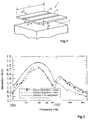
- Figure 1 is a principle drawing of a sound absorbent 1 according to the invention, comprising a panel element 3 with slits 5, arranged at a distance from a rear surface 7.
- Figure 1 indicates the width b of the slit, the distance B between the centre lines of adjacent slits 5, the thickness t of the panel element 3, and the distance d between the panel element 3 and the rear surface 7.
- the drawing in Figure 1 only illustrates the principle of the design, and differs from a genuine embodiment of a sound absorbent according to the invention.
- the slit width b is preferably less than 0.4 mm. Larger slit widths than this will yield poor absorption by friction of viscous flow.
- the slit width b is less than 0.3 mm.
- the distance between the panel element 3 and the rear surface 7 is preferably between 30 and 500 mm. This distance influences the frequency range for which the sound absorbent absorbs, as larger distances result in lower-frequency absorption. To obtain a desired absorption in the speech-range, a distance of 30 to 150 mm will be adequate. If one wants even lower frequency absorption, this distance can be raised to about 500 mm.
- the thickness of the panel element 3, and hence the depth of the slits 5, is advantageously maximum 20 mm, and preferably maximum 10 mm.
- Each sound absorbent 1 in Figure 1 may have a surface area in the region of between about 600 x 600 mm and 1200 x 1800 mm, but can also be shaped into other sizes.
- the sound absorbents 1 can have square or rectangular shapes, which will be suitable for the facing of walls and ceiling, for instance, but may also be produced with other essentially arbitrary shapes.
- the shaping of the sound absorbent will primarily be limited in that an essentially confined space shall exist behind the panel element, the extent of which is at least defined by the panel element and the aforementioned rear surface.
- the relationship between the length L of the slits 5 and the slit width b is advantageously at least 50, and preferably at least 100.
- the slits must have a certain minimum length, as this will reduce the number of work steps during production.
- Figure 2 shows the result of a comparison of the absorption characteristics of a sound absorbing panel with microperforations and a sound absorbent according to the invention.
- the sound absorbing panel with microperforations is known under the name Gema Ultramicro®, and has microperforations of 0.45 mm diameter.
- the characteristics of this product are both measured and estimated.
- the measurements agree well with the estimates.
- the measurements were performed in a reverberation chamber, according to ISO 354.
- the estimates were performed with the software WinFLAGTM.
- DeAmp the characteristics as presented in Figure 2 were estimated.
- the DeAmp sound absorbent has slit widths of 0.2 mm, and both sound absorbents have a distance between the panel element and the rear surface of 200 mm.
- the sound absorbent according to the invention has a higher and broader absorption curve than the sound absorption panel Gema Ultramicro®. Furthermore, they both have their primary absorption range in the frequency range between approximately 100 and 1000 Hz. The measurements for Gema Ultramicro® in the treble range exhibit higher absorption than estimated. This is due to surface absorption, which is not considered in the estimates. A corresponding effect can be expected for the DeAmp sound absorbent.
- the sound absorbent according to the invention can advantageously be produced in metal, such as aluminium or steel, or other hard materials, such as glass, ceramic, rock or hard plastic. It is also possible to manufacture the sound absorbent in certain types of wood or composites of these mentioned materials. The wide range of possible materials renders large possibilities of variation for the appearance of the sound absorbent. Hence it can be adapted to various types of rooms and styles. Furthermore, it is possible to use the panel elements for surfaces other than only ceilings and walls. For instance, they can be shaped as mirrors or associated with windows.
- the panel element of the sound absorbent can be manufactured in different ways, depending on the choice of materials and the various parameters.
- metals laser cutting of slits in a panel element is a cheap and quick way of manufacture.
- Another way is to make smaller panel elements, and to mount these with a distance to each other that corresponds to the desired slit width. This is possible for both metals and glass, but will be most appropriate where laser cutting cannot be used.
- moulding will be a cost efficient way of manufacture.
- the slits can be formed as a zigzag-pattern, instead of being straight as in Figure 1 .
- a zigzag-pattern will result in a longer length of the slit and better absorption properties.
- the slits can also have the shape of letters, or other arbitrary shapes.
- appropriate distance between the slits i.e. the distance between centre lines of adjacent slits, is advantageously between 5 and 75 mm.
- a perforation level in the panel element of less than 3 % is advantageous.
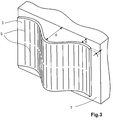
- Figure 3 illustrates an example of a more arbitrary form of the panel element 3 than what is shown in Figure 1 .
- the panel element 3 can also have a varying distance to the rear surface 7, due to the shape of the panel element.
- the illustrated panel element has straight, parallel slits 5. As mentioned, these could also have had a more arbitrary shape, such as letters or other patterns.
- the panel elements 1 stand out as clear, smooth surfaces. Furthermore, the low perforation level causes the elements to reflect much of the light that falls onto them, something that makes them well suited for the use as false ceilings, where it is often desirable to reflect the light.
- a big advantage of the sound absorbent according to the invention is that it tolerates water. Hence, it can be easily washed. It may even be washed with a high-pressure washer, a feature that is very desirable in environments as for instance rooms exposed to moisture, indoor swimming pools, commercial kitchens, and slaughterhouses. Washing is often a problem for fibre-based absorbents, as problems related to decay and mould may arise if they are exposed to moisture.
- the sound absorbents according to the invention can advantageously be manufactured as panels, adapted to be mounted directly onto an existing wall, so that the existing wall functions as the rear surface.
- False ceilings may be manufactured as clamping cassettes, using standardized suspension systems and an independent rear plate.
- the sound absorbent can be manufactured to comprise both the panel element with slits and an additional, rear mounted plate.
Landscapes
- Physics & Mathematics (AREA)
- Engineering & Computer Science (AREA)
- Acoustics & Sound (AREA)
- Architecture (AREA)
- Civil Engineering (AREA)
- Structural Engineering (AREA)
- Electromagnetism (AREA)
- Multimedia (AREA)
- Building Environments (AREA)
- Soundproofing, Sound Blocking, And Sound Damping (AREA)
- Details Of Audible-Bandwidth Transducers (AREA)
Description
- The invention relates to a sound absorbent for absorption of acoustic waves, as stated in the preamble of claim 1.
- In various types of indoor environments, such as office premises, receptions and reception halls, production premises, sports halls and indoor swimming pools, playgrounds and classrooms, it is desirable and also statutory according to regulations, to provide good acoustic conditions to the environment. Acoustic conditions can be best described by the reverberation, and to control this, sound absorbing elements are used, such as sound absorbing panels attached to walls, ceilings, and other surfaces.
- Sound absorbing panels as surfaces for attachment to indoor walls and ceilings come in types that use various physical effects for the absorption of sound. Firstly, there are so-called fibre absorbents. These comprise porous panels of mineral fibres (rock and glass wool), which dampen sound as the sound waves penetrate into the panel, and the energy of the sound waves is reduced by viscous losses in the pores and absorbed by the fibres as heat.
- Furthermore, there exist absorbents, which are based on the Helmholz resonator principle. Such panels generally include slits or apertures, and require fibre fabric or porous fibre materials behind the panel to obtain satisfactory absorption. Normally, a fibre fabric is used, but this is often combined with thicker fibre mats to obtain better absorption. In the latter case, the fibre fabric is often integrated as a surface layer on the fibre mat.
- Another type of absorbent is membrane absorbent. The most common type is thin panels of metal, such as steel or aluminium, or of plastic, which is mounted at a certain distance from a wall or ceiling. A special type is disclosed in patent publication
US 5,719,359 . Here, the sound is absorbed as the sound energy creates movement in a membrane, in the form of thin strips. The general problem with membrane absorbents is that the resistive component, which makes them function as an absorbent, is small, and moreover, is almost impossible to estimate. This is partially solved by arranging the strips against each other, yielding friction as they move as a result of the sound. - Patent publication
US 4,821,841 discloses a panel element for sound absorption, with a panel with slits arranged over a rear plate. The slits are approximately 1.6 to 19 mm wide, and the panel element is adapted to have fibre material arranged in the space between the panel with slits and the rear plate, to obtain the desired absorption. - There are various weaknesses with such fibre-based sound absorbing panels. An important one is that they produce fibres to the environment in the event of damage or wearing. Such fibres are often made of melted glass or rock, and give the sensation of dry air and irritation of the respiratory passages of persons in such environments. Furthermore, these fibres limit the appearance of such plates. It is difficult to keep them clean as they require minimum use of moisture when cleaning, and problems related to mould and decay may arise, especially in rooms exposed to moisture, such as kitchens, indoor swimming pools and the like.
- Another type of panel avoids these drawbacks by using friction by viscous airflow to dampen the sound waves. Such known panels comprise microperforations, i.e. holes through the panel of diameters less than 0.5 mm. These panels are not dependent on fibre materials. The panel is arranged with a distance from a rear surface, in such way that an air space is formed between the microperforated panel and the rear surface. As the sound waves hit the panel, the air in the perforations is forced back and forth due to the pressure differences resulting from the sound waves. This movement results in viscous friction, by which the energy in the sound waves is converted to heat, whereby the sound waves are dampened.
- Such a sound absorbing panel element is disclosed in patent publication
WO 03001501 - Microperforated panels and foils are in many cases produced by rolling a tool with many small spikes over the surface or the foil. Other methods, such as laser cutting and plastic moulding are used for thicker panels and for panels of other materials.
-
WO 00/68039 A1 - A need in the market for new absorbents that allow for architects' desire for a clean and smooth surface is identified. With its low perforation level and special design, the present invention provides a solution to the market, which complies with this need. Products based on the invention can be adapted to the individual customer's needs concerning surface finish, shape, and choice of material.
- The object of the invention is to provide a new type of sound absorbent, which avoids the above-mentioned drawbacks of fibre based sound absorbents, and which simultaneously exhibits better absorption characteristics and is less costly to produce than many known sound absorbents based on microperforations. It is also an object of the invention to open new fields of use and to provide design-related advantages compared to known sound absorbents.
- The object of the invention is achieved by a sound absorbent according to the invention, as described in the characterizing part of claim 1. Additional features of the sound absorbent appear from the accompanying dependent claims.
- It has been recognized that it is possible to produce another type of sound absorbent without fibre materials, which provides good sound absorption using friction of viscous flow. Such a sound absorbent is obtained with a sound absorbent according to the invention, and comprises a panel element with slits there through, which panel element, when in use, is arranged at a distance from a rear surface, creating a space between the panel element and the rear surface. By the term slits is meant slits with a minimum slit width less than 0.45 mm.
- Corresponding to the microperforated panels, with the sound absorbent according to the invention, the sound waves are dampened by friction of viscous flow. Due to pressure changes resulting from the sound waves, the air in the small slits is forced back and forth, and the energy in the sound waves is converted into heat due to the friction of the viscous flow. To obtain this vibration of air in the slits, the rear surface is at a distance from the panel element, so that the air pressure in the air between the panel element and the rear surface will fluctuate due to acoustic waves that impact the panel element and its slits.
- The term panel element herein means the outer part of the sound absorbent, which constitutes a wall or a shell or the like facing the surroundings in such a way that it is arranged between the surroundings and a rear space, which rear space is at least partially confined by the panel element and the mentioned rear surface. Thus, by using the term panel element, it is not intended to limit the shape to a planar shaped plate. Hence, the sound absorbent's panel element can essentially be shaped to an arbitrary form, for instance a ball, a rod, or a more "organic" arbitrary form, as long as the principle for sound absorption according to the present invention is ensured.
- The panel element of the sound absorbent is made of a hard material, such as metal, glass, ceramics, hard plastic etc. Herein hard material means materials that are so hard that their surface will not vibrate essentially in relation to the surrounding air when the surrounding air pressure fluctuates, or the surrounding air vibrates, respectively, as a result of acoustic waves. Hence, the term materials means materials that are sufficiently hard to ensure the mode of operation according to the invention.
- The sound absorbent according to the invention is primarily intended for use on walls and ceilings and other surfaces in building rooms. However, it may also be used for sound dampening of various sources of noise, such as engines, or as sound absorbent for other arrangements, such as in buses or trains, or in ventilating systems.
- The absorption characteristic of the sound absorbent according to the invention is dependent on various parameters. Such parameters comprise slit width, slit distance, panel element thickness, and the distance between the panel element and the rear surface. In rooms with noise in the form of speech, such as in indoor swimming pools, conference rooms, office premises, reception halls and class rooms, it is desired that the sound absorbent primarily absorbs sound with frequencies in the speech range, i.e. approximately 250 - 4000 Hz. In such rooms, speech communication is important, and thus the use of sound absorbents to optimize the reverberation is important. High frequencies are normally sufficiently absorbed by other parts of the interior, such as furniture, curtains, persons and carpets. The mentioned parameters can thus be set in such a way that the sound absorbent absorbs especially well at low and medium frequencies. The sound absorbent will preferably be adapted to absorb in the frequency range between 100 and 2000 Hz, and can also be adapted to absorb in the frequency range between 100 and 4000 Hz.
- In the following is presented an example of an embodiment of a sound absorbing sound absorbent according to the invention, with reference to the drawings, where
-
Figure 1 illustrates a principle drawing of a sound absorbent according to the invention; -
Figure 2 illustrates a comparison of the absorption characteristics of a known sound absorbing panel with microperforations and a sound absorbent according to the invention; and -
Figure 3 illustrates a more arbitrary shape of the panel element of a sound absorbent according to the invention. -
Figure 1 is a principle drawing of a sound absorbent 1 according to the invention, comprising apanel element 3 withslits 5, arranged at a distance from arear surface 7. Of the four parameters mentioned above,Figure 1 indicates the width b of the slit, the distance B between the centre lines ofadjacent slits 5, the thickness t of thepanel element 3, and the distance d between thepanel element 3 and therear surface 7. The drawing inFigure 1 only illustrates the principle of the design, and differs from a genuine embodiment of a sound absorbent according to the invention. - The slit width b is preferably less than 0.4 mm. Larger slit widths than this will yield poor absorption by friction of viscous flow. Advantageously, the slit width b is less than 0.3 mm. The distance between the
panel element 3 and therear surface 7 is preferably between 30 and 500 mm. This distance influences the frequency range for which the sound absorbent absorbs, as larger distances result in lower-frequency absorption. To obtain a desired absorption in the speech-range, a distance of 30 to 150 mm will be adequate. If one wants even lower frequency absorption, this distance can be raised to about 500 mm. The thickness of thepanel element 3, and hence the depth of theslits 5, is advantageously maximum 20 mm, and preferably maximum 10 mm. This relates to both the absorption spectrum and the cost aspect. With a thicker panel element, one will obtain a narrow absorption spectrum, something that one wants to avoid, as one wants a sound absorbent that absorbs in a wide frequency range. Furthermore, it is cheaper to produce with thinner panel elements. - Each sound absorbent 1 in
Figure 1 may have a surface area in the region of between about 600 x 600 mm and 1200 x 1800 mm, but can also be shaped into other sizes. The sound absorbents 1 can have square or rectangular shapes, which will be suitable for the facing of walls and ceiling, for instance, but may also be produced with other essentially arbitrary shapes. The shaping of the sound absorbent will primarily be limited in that an essentially confined space shall exist behind the panel element, the extent of which is at least defined by the panel element and the aforementioned rear surface. - The relationship between the length L of the
slits 5 and the slit width b is advantageously at least 50, and preferably at least 100. To achieve the production-related advantages of slits in lieu of holes, the slits must have a certain minimum length, as this will reduce the number of work steps during production. -
Figure 2 shows the result of a comparison of the absorption characteristics of a sound absorbing panel with microperforations and a sound absorbent according to the invention. The sound absorbing panel with microperforations is known under the name Gema Ultramicro®, and has microperforations of 0.45 mm diameter. The characteristics of this product are both measured and estimated. As appears fromFigure 2 , the measurements agree well with the estimates. The measurements were performed in a reverberation chamber, according to ISO 354. The estimates were performed with the software WinFLAG™. For the sound absorbent according to the invention, here with a planar/plate form, called DeAmp, the characteristics as presented inFigure 2 were estimated. Other variants of the DeAmp sound absorbents have been measured with both small and large samples, and the tests agree well with the estimates. The DeAmp sound absorbent has slit widths of 0.2 mm, and both sound absorbents have a distance between the panel element and the rear surface of 200 mm. As appears fromFigure 2 , the sound absorbent according to the invention has a higher and broader absorption curve than the sound absorption panel Gema Ultramicro®. Furthermore, they both have their primary absorption range in the frequency range between approximately 100 and 1000 Hz. The measurements for Gema Ultramicro® in the treble range exhibit higher absorption than estimated. This is due to surface absorption, which is not considered in the estimates. A corresponding effect can be expected for the DeAmp sound absorbent. - The comparison described above with reference to
Figure 2 , illustrates that the sound absorbent according to the invention absorbs sound better than the mentioned product with microperforations for the same frequency range. - To achieve a better absorption characteristic, i.e. a broader and/or higher absorption curve (
Figure 2 ), it is possible to arrange one or more additional panel elements with slits between the rear surface and the panel element described above. This or these panel element(s) may have different slit widths, distances between the slits, and panel thicknesses. In this way it is possible to design a sound absorbent according to the invention with desired absorption characteristics. - It is also possible to arrange other, known types of sound absorbents between the panel element and the rear surface to achieve the desired absorption characteristics.
- The sound absorbent according to the invention, and especially its panel element, can advantageously be produced in metal, such as aluminium or steel, or other hard materials, such as glass, ceramic, rock or hard plastic. It is also possible to manufacture the sound absorbent in certain types of wood or composites of these mentioned materials. The wide range of possible materials renders large possibilities of variation for the appearance of the sound absorbent. Hence it can be adapted to various types of rooms and styles. Furthermore, it is possible to use the panel elements for surfaces other than only ceilings and walls. For instance, they can be shaped as mirrors or associated with windows.
- The panel element of the sound absorbent can be manufactured in different ways, depending on the choice of materials and the various parameters. For metals, laser cutting of slits in a panel element is a cheap and quick way of manufacture. Another way is to make smaller panel elements, and to mount these with a distance to each other that corresponds to the desired slit width. This is possible for both metals and glass, but will be most appropriate where laser cutting cannot be used. For sound absorbents in plastic, moulding will be a cost efficient way of manufacture.
- These production methods provide great flexibility for the design. For instance, the slits can be formed as a zigzag-pattern, instead of being straight as in
Figure 1 . A zigzag-pattern will result in a longer length of the slit and better absorption properties. The slits can also have the shape of letters, or other arbitrary shapes. - For slits that are essentially mutually parallel to adjacent slits, such as straight, wave-shaped, or zigzag-shaped slits, appropriate distance between the slits, i.e. the distance between centre lines of adjacent slits, is advantageously between 5 and 75 mm.
- In general, for slits of arbitrary shape, such as slits shaped as letters or other patterns, for instance, a perforation level in the panel element of less than 3 % is advantageous.
-
Figure 3 illustrates an example of a more arbitrary form of thepanel element 3 than what is shown inFigure 1 . As appears fromFigure 3 , thepanel element 3 can also have a varying distance to therear surface 7, due to the shape of the panel element. The illustrated panel element has straight,parallel slits 5. As mentioned, these could also have had a more arbitrary shape, such as letters or other patterns. - Because of the small slit widths b in the
panel 3, theslits 5 will barely be visible. Hence, the panel elements 1 stand out as clear, smooth surfaces. Furthermore, the low perforation level causes the elements to reflect much of the light that falls onto them, something that makes them well suited for the use as false ceilings, where it is often desirable to reflect the light. - A big advantage of the sound absorbent according to the invention is that it tolerates water. Hence, it can be easily washed. It may even be washed with a high-pressure washer, a feature that is very desirable in environments as for instance rooms exposed to moisture, indoor swimming pools, commercial kitchens, and slaughterhouses. Washing is often a problem for fibre-based absorbents, as problems related to decay and mould may arise if they are exposed to moisture.
- The sound absorbents according to the invention can advantageously be manufactured as panels, adapted to be mounted directly onto an existing wall, so that the existing wall functions as the rear surface. False ceilings may be manufactured as clamping cassettes, using standardized suspension systems and an independent rear plate. Alternatively, the sound absorbent can be manufactured to comprise both the panel element with slits and an additional, rear mounted plate.
Claims (10)
- Sound absorbent of a hard material, for absorption of acoustic waves by friction of viscous flow, essentially in the frequency range between 100 and 4000 Hz, consisting of:- a panel element (3) having slits (5) there through which are mutually parallel,
where the slits (5) have a length L, a width b, and are spaced a distance B from each other as measured from a center line of adjacent slits,
and- a rear surface (7) arranged at a distance d from the panel element (3),
wherein- the ratio between the Length L and width b is at least 50,- the width b is less than 0.4 mm,- the panel (3) has a thickness t less than 20 mm,
characterised in that:the distance B between adjacent slits (5) is between 5 and 75 mm, and- the distance d is between 30 and 500 mm. - Sound absorbent according to claim 1, characterized in that the ratio between the length (L) and the width (b) of the slits (5) is at least 100.
- Sound absorbent according to any one of the preceding claims, characterized in that the maximum thickness (t) of the panel element (3) is 10 mm.
- Sound absorbent according to any one of the preceding claims, characterized in that the width (b) of the slits (5) is less than 0.3 mm.
- Sound absorbent according to any one of the preceding claims, characterized in that the panel element (3) comprises wood.
- Sound absorbent according to any one of the preceding claims, characterized in that it essentially comprises glass or acrylic, and is adapted for use as a part of a transparent implementation.
- Sound absorbent according to any one of the preceding claims, characterized in that the slits (5) are manufactured by use of laser.
- Sound absorbent according to any one of claims 1- 6 , characterized in that the slits (5) are created by separate panel elements (3) being arranged adjacent each other with spaces corresponding to the slit(s) (5).
- Sound absorbent according to any of preceding claim, characterized in that the hard material is chosen from one of; metal, glass, hard plastic or composites thereof.
- Sound absorbent according to any one of claims 1- 6, characterized in that the slits (5) are given one of the following shapes; straight, wave-shaped or zigzag-shaped.
Priority Applications (1)
| Application Number | Priority Date | Filing Date | Title |
|---|---|---|---|
| PL06716779T PL1861554T3 (en) | 2005-03-23 | 2006-03-23 | Sound absorbent |
Applications Claiming Priority (2)
| Application Number | Priority Date | Filing Date | Title |
|---|---|---|---|
| NO20051536A NO322685B1 (en) | 2005-03-23 | 2005-03-23 | Plate Element |
| PCT/NO2006/000110 WO2006101403A1 (en) | 2005-03-23 | 2006-03-23 | Sound absorbent |
Publications (3)
| Publication Number | Publication Date |
|---|---|
| EP1861554A1 EP1861554A1 (en) | 2007-12-05 |
| EP1861554A4 EP1861554A4 (en) | 2010-05-05 |
| EP1861554B1 true EP1861554B1 (en) | 2016-10-19 |
Family
ID=35267123
Family Applications (1)
| Application Number | Title | Priority Date | Filing Date |
|---|---|---|---|
| EP06716779.1A Revoked EP1861554B1 (en) | 2005-03-23 | 2006-03-23 | Sound absorbent |
Country Status (10)
| Country | Link |
|---|---|
| US (1) | US7677359B2 (en) |
| EP (1) | EP1861554B1 (en) |
| JP (1) | JP2008534820A (en) |
| KR (1) | KR20070112398A (en) |
| CA (1) | CA2602301A1 (en) |
| DK (1) | DK1861554T3 (en) |
| ES (1) | ES2609411T3 (en) |
| NO (1) | NO322685B1 (en) |
| PL (1) | PL1861554T3 (en) |
| WO (1) | WO2006101403A1 (en) |
Cited By (1)
| Publication number | Priority date | Publication date | Assignee | Title |
|---|---|---|---|---|
| RU238678U1 (en) * | 2025-06-17 | 2025-11-07 | Общество с ограниченной ответственностью "АПС-ТЕХНОЛОДЖИ" | SOUND ABSORBING PANEL |
Families Citing this family (31)
| Publication number | Priority date | Publication date | Assignee | Title |
|---|---|---|---|---|
| EP1768100A1 (en) * | 2005-09-22 | 2007-03-28 | USM Holding AG | Furniture influencing the room acoustics |
| EP1950357B1 (en) * | 2007-01-29 | 2010-08-18 | Albers & Co. | Acoustic elements |
| GB2461909A (en) * | 2008-07-17 | 2010-01-20 | South Bank Univ Entpr Ltd | Sound absorbing device |
| US9607600B2 (en) * | 2009-02-06 | 2017-03-28 | Sonobex Limited | Attenuators, arrangements of attenuators, acoustic barriers and methods for constructing acoustic barriers |
| CH700971A1 (en) * | 2009-05-04 | 2010-11-15 | Albers & Co | Flexible glass elements. |
| EP2256722A1 (en) | 2009-05-29 | 2010-12-01 | Akusik & Innovation GmbH | Acoustic dampening and absorbing material |
| US9388731B2 (en) | 2013-03-15 | 2016-07-12 | Kohler Co. | Noise suppression system |
| US9752494B2 (en) | 2013-03-15 | 2017-09-05 | Kohler Co. | Noise suppression systems |
| NZ623604A (en) * | 2013-04-08 | 2015-05-29 | Csr Building Products Ltd | Sound attenuating structure |
| JP6261942B2 (en) * | 2013-10-25 | 2018-01-17 | 三井住友建設株式会社 | Tunnel low frequency sound reduction device |
| NO337032B1 (en) * | 2014-04-29 | 2016-01-04 | Deamp As | Sound absorbing film |
| US9251778B2 (en) * | 2014-06-06 | 2016-02-02 | Industrial Technology Research Institute | Metal foil with microcracks, method of manufacturing the same, and sound-absorbing structure having the same |
| CN107002403B (en) * | 2014-12-05 | 2021-03-16 | 艾勒达有限责任公司 | Sound Absorbing Components and Systems |
| AU362291S (en) | 2015-05-08 | 2015-06-15 | Extrusion | |
| AU362290S (en) | 2015-05-08 | 2015-06-15 | Extrusion | |
| US10068563B2 (en) | 2015-11-18 | 2018-09-04 | Rpg Acoustical Systems Llc | Sound absorbing panel with wedge-shaped cross-section micro-slits |
| US10315480B2 (en) | 2015-12-18 | 2019-06-11 | Fox Factory, Inc. | Adjustable floating traction bar |
| US11608291B2 (en) | 2016-11-04 | 2023-03-21 | Corning Incorporated | Micro-perforated panel systems, applications, and methods of making micro-perforated panel systems |
| CN110573470A (en) * | 2017-04-26 | 2019-12-13 | 康宁股份有限公司 | Microperforated glass laminate and method of manufacturing the same |
| CN110832576B (en) * | 2017-07-28 | 2023-05-26 | 揖斐电株式会社 | Sound absorbing member, vehicle component, and automobile |
| US10847081B2 (en) | 2018-03-23 | 2020-11-24 | Abl Ip Holding Llc | Configurable lighting device incorporating noise reduction |
| USD895159S1 (en) | 2018-04-13 | 2020-09-01 | Caimi Brevetti S.P.A. | Sound absorbing panel |
| USD894429S1 (en) | 2018-04-13 | 2020-08-25 | Caimi Brevetti S.P.A. | Sound absorbing panel |
| USD895158S1 (en) | 2018-04-13 | 2020-09-01 | Caimi Brevetti S.P.A. | Sound absorbing panel |
| TWI669430B (en) * | 2018-10-31 | 2019-08-21 | 許翃銘 | Sound-absorbing panels |
| CN109559728A (en) * | 2018-11-26 | 2019-04-02 | 中国人民解放军国防科技大学 | Broadband sound absorption structure of zigzag cavity micro-perforated plate |
| US10586525B1 (en) * | 2019-06-18 | 2020-03-10 | RPG Acoustical Systems, LLC | Array of acoustical returner devices to reflect sound back in the incident direction |
| CN112185327A (en) * | 2020-09-16 | 2021-01-05 | 西安交通大学 | Micro-seam low-frequency sound absorption unit and nested broadband sound absorption structure with same |
| US12492654B2 (en) | 2022-03-04 | 2025-12-09 | Acs Industries, Inc. | Sound absorbing element with low profile micro-louver slits and muffler assembly using the same |
| IT202300002286A1 (en) * | 2023-02-10 | 2024-08-10 | Pantecnica S P A | NOISE REDUCTION DEVICE FOR BIOMASS HEATING SYSTEMS |
| DE102024208913A1 (en) * | 2024-09-18 | 2026-03-19 | Fraunhofer-Gesellschaft zur Förderung der angewandten Forschung eingetragener Verein | Sound absorber |
Citations (11)
| Publication number | Priority date | Publication date | Assignee | Title |
|---|---|---|---|---|
| DE9116233U1 (en) | 1991-04-10 | 1992-06-17 | VEGLA Vereinigte Glaswerke GmbH, 5100 Aachen | Sound-absorbing glazing |
| DE4315759C1 (en) | 1993-05-11 | 1994-05-05 | Fraunhofer Ges Forschung | Sound-absorbent glazing for building - comprises perforated plate with small-diameter holes close together |
| DE4316843A1 (en) | 1993-05-19 | 1994-11-24 | Messer Griesheim Gmbh | Method of perforating three-dimensional or planar components |
| WO1997027370A1 (en) | 1996-01-25 | 1997-07-31 | Sontech Ab | Soundabsorbing element and procedure for manufacture of this element and use of this element |
| US5719359A (en) | 1994-05-09 | 1998-02-17 | Woco Franz-Josef Wolf & Co. | Laminar damper |
| US5740649A (en) | 1993-04-20 | 1998-04-21 | Fraunhofer-Gesellschaft Zur Forderung Der Angewandten Forschung E.V. | False ceiling |
| DE19754107C1 (en) | 1997-12-05 | 1999-02-25 | Fraunhofer Ges Forschung | Sound absorber, for suspension from ceiling |
| WO2000068039A1 (en) | 1999-05-06 | 2000-11-16 | Faist Automotive Gmbh & Co. Kg | Sound-shielding element, use thereof and method for producing the same |
| EP1146178A2 (en) | 2000-04-14 | 2001-10-17 | FAIST Automotive GmbH & Co. KG | Wide spectrum sound absorbtion building element for walls, floors and ceilings |
| WO2003008725A1 (en) | 2001-07-16 | 2003-01-30 | Enac S.A. | Sonic absorption device for premises |
| WO2003030144A1 (en) | 2001-09-27 | 2003-04-10 | Faist Automotive Gmbh & Co. Kg | Sound-shielding, soundproofing and/or sound-absorbing device, use thereof and production of the same |
Family Cites Families (14)
| Publication number | Priority date | Publication date | Assignee | Title |
|---|---|---|---|---|
| US194052A (en) * | 1877-08-14 | Improvement in crosscut-saw handles | ||
| US740649A (en) * | 1903-06-23 | 1903-10-06 | Hero Fruit Jar Company | Insulating handle connection. |
| US1536666A (en) * | 1924-02-27 | 1925-05-05 | Philip S Chess | Wall structure |
| US3269484A (en) * | 1963-09-24 | 1966-08-30 | Lighter Stephen | Acoustic absorbing structure |
| US4821841A (en) | 1987-06-16 | 1989-04-18 | Bruce Woodward | Sound absorbing structures |
| JPH02136407A (en) * | 1988-11-17 | 1990-05-25 | Kenon Eng:Kk | Soundproof fence |
| JPH0723631B2 (en) * | 1988-11-18 | 1995-03-15 | 株式会社ノザワ | Method for manufacturing resonator type soundproof panel |
| JP2815542B2 (en) * | 1994-08-31 | 1998-10-27 | 三菱電機ホーム機器株式会社 | Sound absorption mechanism using porous structure |
| US6021612A (en) * | 1995-09-08 | 2000-02-08 | C&D Technologies, Inc. | Sound absorptive hollow core structural panel |
| US6617002B2 (en) * | 1998-07-24 | 2003-09-09 | Minnesota Mining And Manufacturing Company | Microperforated polymeric film for sound absorption and sound absorber using same |
| US6598701B1 (en) * | 2000-06-30 | 2003-07-29 | 3M Innovative Properties Company | Shaped microperforated polymeric film sound absorbers and methods of manufacturing the same |
| US7434660B2 (en) * | 2001-06-21 | 2008-10-14 | Kabushiki Kaisha Kobe Seiko Sho | Perforated soundproof structure and method of manufacturing the same |
| KR100787297B1 (en) * | 2003-09-05 | 2007-12-20 | 가부시키가이샤 고베 세이코쇼 | Sound absorbing structure and method of producing the same |
| JP4829218B2 (en) * | 2005-03-30 | 2011-12-07 | パナソニック株式会社 | Sound absorbing structure |
-
2005
- 2005-03-23 NO NO20051536A patent/NO322685B1/en unknown
-
2006
- 2006-03-23 ES ES06716779.1T patent/ES2609411T3/en not_active Expired - Lifetime
- 2006-03-23 WO PCT/NO2006/000110 patent/WO2006101403A1/en not_active Ceased
- 2006-03-23 KR KR1020077022642A patent/KR20070112398A/en not_active Ceased
- 2006-03-23 US US11/816,590 patent/US7677359B2/en active Active
- 2006-03-23 CA CA002602301A patent/CA2602301A1/en not_active Abandoned
- 2006-03-23 EP EP06716779.1A patent/EP1861554B1/en not_active Revoked
- 2006-03-23 JP JP2008502937A patent/JP2008534820A/en active Pending
- 2006-03-23 DK DK06716779.1T patent/DK1861554T3/en active
- 2006-03-23 PL PL06716779T patent/PL1861554T3/en unknown
Patent Citations (12)
| Publication number | Priority date | Publication date | Assignee | Title |
|---|---|---|---|---|
| DE9116233U1 (en) | 1991-04-10 | 1992-06-17 | VEGLA Vereinigte Glaswerke GmbH, 5100 Aachen | Sound-absorbing glazing |
| US5740649A (en) | 1993-04-20 | 1998-04-21 | Fraunhofer-Gesellschaft Zur Forderung Der Angewandten Forschung E.V. | False ceiling |
| DE4315759C1 (en) | 1993-05-11 | 1994-05-05 | Fraunhofer Ges Forschung | Sound-absorbent glazing for building - comprises perforated plate with small-diameter holes close together |
| US5700527A (en) | 1993-05-11 | 1997-12-23 | Fraunhofer-Gesellschaft Zur Foerderung Der Angewandten Forschung E.V. | Sound-absorbing glass building component or transparent synthetic glass building component |
| DE4316843A1 (en) | 1993-05-19 | 1994-11-24 | Messer Griesheim Gmbh | Method of perforating three-dimensional or planar components |
| US5719359A (en) | 1994-05-09 | 1998-02-17 | Woco Franz-Josef Wolf & Co. | Laminar damper |
| WO1997027370A1 (en) | 1996-01-25 | 1997-07-31 | Sontech Ab | Soundabsorbing element and procedure for manufacture of this element and use of this element |
| DE19754107C1 (en) | 1997-12-05 | 1999-02-25 | Fraunhofer Ges Forschung | Sound absorber, for suspension from ceiling |
| WO2000068039A1 (en) | 1999-05-06 | 2000-11-16 | Faist Automotive Gmbh & Co. Kg | Sound-shielding element, use thereof and method for producing the same |
| EP1146178A2 (en) | 2000-04-14 | 2001-10-17 | FAIST Automotive GmbH & Co. KG | Wide spectrum sound absorbtion building element for walls, floors and ceilings |
| WO2003008725A1 (en) | 2001-07-16 | 2003-01-30 | Enac S.A. | Sonic absorption device for premises |
| WO2003030144A1 (en) | 2001-09-27 | 2003-04-10 | Faist Automotive Gmbh & Co. Kg | Sound-shielding, soundproofing and/or sound-absorbing device, use thereof and production of the same |
Non-Patent Citations (8)
| Title |
|---|
| "Hochdämmendes und hochabsorbierendes Studio-Fenster in leichter Modul- bauweise", IBP-MITTEILUNG 266, vol. 22, 1995, Brüssau , Fuchs, Hunecke, Zha, pages 1 - 2 |
| HINHÖREN UND HINSEHEN: SOLCHE AKUSTIK GAB'S NOCH NIE, pages 1 - 6 |
| INGARD: "Notes on Sound Absorption Technology", NOISE CONTROL FOUNDATION, 1994, pages 3 - 1 - 3-10, 3-16 and E-44, XP055398845 |
| MAA: "Theory of Microslit Absorber s", CHINESE JOURNAL OF ACOUSTICS, vol. 20, no. 1, 2001, pages 1 - 10, XP055398844 |
| MEI Q. WU: "Micro-perforated panels for duct silencing", NOISE CONTROL ENGINEERING JOURNAL, vol. 45, no. 2, March 1997 (1997-03-01), pages 69 - 76, XP055370093 |
| MICHAEL BRÜSSAU: "Hochdämmendes schallabsorbierendes Regiefenster", STUDIENGANG BAUPHYSIK DER FACHHOCHSCHULE FÜR TECHNIK, January 1995 (1995-01-01), Stuttgart, pages 1 - 39 |
| PRINTSCREEN OF WEBPAGE OF HOCHSCHULE FÜR TECHNIK, Stuttgart |
| ROLF TORE RANDEBERG ET AL.: "Perforated Panel Absorbers with Viscous Energy Dissipation Enhanced by Orifice Design", DOCTORAL THESIS, DEPARTMENT OF TELECOMMUNI- CATIONS, June 2000 (2000-06-01), Trondheim, pages 10 - 12 , 18-22 and 58-95, XP055398843 |
Cited By (1)
| Publication number | Priority date | Publication date | Assignee | Title |
|---|---|---|---|---|
| RU238678U1 (en) * | 2025-06-17 | 2025-11-07 | Общество с ограниченной ответственностью "АПС-ТЕХНОЛОДЖИ" | SOUND ABSORBING PANEL |
Also Published As
| Publication number | Publication date |
|---|---|
| NO20051536D0 (en) | 2005-03-23 |
| US20080264720A1 (en) | 2008-10-30 |
| DK1861554T3 (en) | 2017-02-06 |
| WO2006101403A1 (en) | 2006-09-28 |
| KR20070112398A (en) | 2007-11-23 |
| US7677359B2 (en) | 2010-03-16 |
| CA2602301A1 (en) | 2006-09-28 |
| ES2609411T3 (en) | 2017-04-20 |
| NO322685B1 (en) | 2006-11-27 |
| JP2008534820A (en) | 2008-08-28 |
| PL1861554T3 (en) | 2017-04-28 |
| EP1861554A1 (en) | 2007-12-05 |
| EP1861554A4 (en) | 2010-05-05 |
Similar Documents
| Publication | Publication Date | Title |
|---|---|---|
| US7677359B2 (en) | Sound absorbent | |
| US8906486B2 (en) | Flexible sheet materials for tensioned structures, a method of making such materials, and tensioned false ceilings comprising such materials | |
| CA2243950C (en) | Soundabsorbing element and procedure for manufacture of this element and use of this element | |
| US6675551B1 (en) | Plate-shaped constructional element and method | |
| US5740649A (en) | False ceiling | |
| KR101960823B1 (en) | Sound absorbing structure for anechoic chamber and anechoic chamber including the same | |
| US6015026A (en) | Acoustical diffuser assembly and method of installation | |
| WO2000034595A1 (en) | Dual sonic character acoustic panel and systems for use thereof | |
| JP2008544119A (en) | Sound absorption panel | |
| JP2017020291A (en) | Perforated sound absorbing board and sound absorbing structure | |
| KR20220113127A (en) | A acoustic board with improved diffusing performance with grooved polyester sound absorbing felter | |
| KR100468296B1 (en) | Panel for soundproofing and plate with numerous holes for the panel | |
| JP2018537604A (en) | Soundproof drywall panel | |
| US6615951B1 (en) | Absorbent material, consisting of a porous substance with double porosity | |
| CN109312563A (en) | Sound absorber facilities and soundproofed rooms | |
| KR20110004627U (en) | Sound absorption panel | |
| KR20170095575A (en) | Noise Absorbing Panel | |
| JP6054144B2 (en) | Sound absorption panel | |
| KR101261050B1 (en) | Porosity soundproof plate for room | |
| RU2238378C2 (en) | Flexible sheet material for stretched structure, method of its production and sheet material for stretched suspended ceiling | |
| KR102453593B1 (en) | SOUND ABSORBING PANEL BY USING Helmholtz RESONANCE PRINCIPLE | |
| JP7637530B2 (en) | Sound absorbing structure | |
| WO2018211120A1 (en) | Improvements in and relating to acoustics panels | |
| KR200163303Y1 (en) | Soundproofing structural seat | |
| JP2022129182A (en) | Louver material and sound absorbing structure |
Legal Events
| Date | Code | Title | Description |
|---|---|---|---|
| PUAI | Public reference made under article 153(3) epc to a published international application that has entered the european phase |
Free format text: ORIGINAL CODE: 0009012 |
|
| 17P | Request for examination filed |
Effective date: 20071005 |
|
| AK | Designated contracting states |
Kind code of ref document: A1 Designated state(s): AT BE BG CH CY CZ DE DK EE ES FI FR GB GR HU IE IS IT LI LT LU LV MC NL PL PT RO SE SI SK TR |
|
| DAX | Request for extension of the european patent (deleted) | ||
| TPAC | Observations filed by third parties |
Free format text: ORIGINAL CODE: EPIDOSNTIPA |
|
| A4 | Supplementary search report drawn up and despatched |
Effective date: 20100407 |
|
| 17Q | First examination report despatched |
Effective date: 20110103 |
|
| TPAC | Observations filed by third parties |
Free format text: ORIGINAL CODE: EPIDOSNTIPA |
|
| TPAC | Observations filed by third parties |
Free format text: ORIGINAL CODE: EPIDOSNTIPA |
|
| TPAC | Observations filed by third parties |
Free format text: ORIGINAL CODE: EPIDOSNTIPA |
|
| GRAP | Despatch of communication of intention to grant a patent |
Free format text: ORIGINAL CODE: EPIDOSNIGR1 |
|
| INTG | Intention to grant announced |
Effective date: 20160617 |
|
| RIN1 | Information on inventor provided before grant (corrected) |
Inventor name: VIGRAN, TOR, ERIK Inventor name: PETTERSEN, ODD |
|
| GRAS | Grant fee paid |
Free format text: ORIGINAL CODE: EPIDOSNIGR3 |
|
| GRAA | (expected) grant |
Free format text: ORIGINAL CODE: 0009210 |
|
| AK | Designated contracting states |
Kind code of ref document: B1 Designated state(s): AT BE BG CH CY CZ DE DK EE ES FI FR GB GR HU IE IS IT LI LT LU LV MC NL PL PT RO SE SI SK TR |
|
| RAP1 | Party data changed (applicant data changed or rights of an application transferred) |
Owner name: DEAMP AS |
|
| REG | Reference to a national code |
Ref country code: GB Ref legal event code: FG4D |
|
| REG | Reference to a national code |
Ref country code: CH Ref legal event code: EP |
|
| REG | Reference to a national code |
Ref country code: AT Ref legal event code: REF Ref document number: 838481 Country of ref document: AT Kind code of ref document: T Effective date: 20161115 |
|
| REG | Reference to a national code |
Ref country code: IE Ref legal event code: FG4D |
|
| REG | Reference to a national code |
Ref country code: DE Ref legal event code: R096 Ref document number: 602006050607 Country of ref document: DE |
|
| REG | Reference to a national code |
Ref country code: CH Ref legal event code: NV Representative=s name: SCHNEIDER FELDMANN AG PATENT- UND MARKENANWAEL, CH |
|
| REG | Reference to a national code |
Ref country code: NL Ref legal event code: FP |
|
| REG | Reference to a national code |
Ref country code: DK Ref legal event code: T3 Effective date: 20170131 |
|
| REG | Reference to a national code |
Ref country code: SE Ref legal event code: TRGR |
|
| REG | Reference to a national code |
Ref country code: LT Ref legal event code: MG4D |
|
| PG25 | Lapsed in a contracting state [announced via postgrant information from national office to epo] |
Ref country code: LV Free format text: LAPSE BECAUSE OF FAILURE TO SUBMIT A TRANSLATION OF THE DESCRIPTION OR TO PAY THE FEE WITHIN THE PRESCRIBED TIME-LIMIT Effective date: 20161019 |
|
| REG | Reference to a national code |
Ref country code: AT Ref legal event code: MK05 Ref document number: 838481 Country of ref document: AT Kind code of ref document: T Effective date: 20161019 |
|
| REG | Reference to a national code |
Ref country code: FR Ref legal event code: PLFP Year of fee payment: 12 |
|
| REG | Reference to a national code |
Ref country code: ES Ref legal event code: FG2A Ref document number: 2609411 Country of ref document: ES Kind code of ref document: T3 Effective date: 20170420 |
|
| PG25 | Lapsed in a contracting state [announced via postgrant information from national office to epo] |
Ref country code: LT Free format text: LAPSE BECAUSE OF FAILURE TO SUBMIT A TRANSLATION OF THE DESCRIPTION OR TO PAY THE FEE WITHIN THE PRESCRIBED TIME-LIMIT Effective date: 20161019 Ref country code: GR Free format text: LAPSE BECAUSE OF FAILURE TO SUBMIT A TRANSLATION OF THE DESCRIPTION OR TO PAY THE FEE WITHIN THE PRESCRIBED TIME-LIMIT Effective date: 20170120 |
|
| PG25 | Lapsed in a contracting state [announced via postgrant information from national office to epo] |
Ref country code: PT Free format text: LAPSE BECAUSE OF FAILURE TO SUBMIT A TRANSLATION OF THE DESCRIPTION OR TO PAY THE FEE WITHIN THE PRESCRIBED TIME-LIMIT Effective date: 20170220 Ref country code: IS Free format text: LAPSE BECAUSE OF FAILURE TO SUBMIT A TRANSLATION OF THE DESCRIPTION OR TO PAY THE FEE WITHIN THE PRESCRIBED TIME-LIMIT Effective date: 20170219 Ref country code: FI Free format text: LAPSE BECAUSE OF FAILURE TO SUBMIT A TRANSLATION OF THE DESCRIPTION OR TO PAY THE FEE WITHIN THE PRESCRIBED TIME-LIMIT Effective date: 20161019 Ref country code: AT Free format text: LAPSE BECAUSE OF FAILURE TO SUBMIT A TRANSLATION OF THE DESCRIPTION OR TO PAY THE FEE WITHIN THE PRESCRIBED TIME-LIMIT Effective date: 20161019 |
|
| REG | Reference to a national code |
Ref country code: DE Ref legal event code: R026 Ref document number: 602006050607 Country of ref document: DE |
|
| PLBI | Opposition filed |
Free format text: ORIGINAL CODE: 0009260 |
|
| PG25 | Lapsed in a contracting state [announced via postgrant information from national office to epo] |
Ref country code: EE Free format text: LAPSE BECAUSE OF FAILURE TO SUBMIT A TRANSLATION OF THE DESCRIPTION OR TO PAY THE FEE WITHIN THE PRESCRIBED TIME-LIMIT Effective date: 20161019 Ref country code: SK Free format text: LAPSE BECAUSE OF FAILURE TO SUBMIT A TRANSLATION OF THE DESCRIPTION OR TO PAY THE FEE WITHIN THE PRESCRIBED TIME-LIMIT Effective date: 20161019 Ref country code: CZ Free format text: LAPSE BECAUSE OF FAILURE TO SUBMIT A TRANSLATION OF THE DESCRIPTION OR TO PAY THE FEE WITHIN THE PRESCRIBED TIME-LIMIT Effective date: 20161019 Ref country code: RO Free format text: LAPSE BECAUSE OF FAILURE TO SUBMIT A TRANSLATION OF THE DESCRIPTION OR TO PAY THE FEE WITHIN THE PRESCRIBED TIME-LIMIT Effective date: 20161019 |
|
| 26 | Opposition filed |
Opponent name: SONTECH INTERNATIONAL AB Effective date: 20170710 |
|
| PLAX | Notice of opposition and request to file observation + time limit sent |
Free format text: ORIGINAL CODE: EPIDOSNOBS2 |
|
| PG25 | Lapsed in a contracting state [announced via postgrant information from national office to epo] |
Ref country code: BG Free format text: LAPSE BECAUSE OF FAILURE TO SUBMIT A TRANSLATION OF THE DESCRIPTION OR TO PAY THE FEE WITHIN THE PRESCRIBED TIME-LIMIT Effective date: 20170119 |
|
| PG25 | Lapsed in a contracting state [announced via postgrant information from national office to epo] |
Ref country code: SI Free format text: LAPSE BECAUSE OF FAILURE TO SUBMIT A TRANSLATION OF THE DESCRIPTION OR TO PAY THE FEE WITHIN THE PRESCRIBED TIME-LIMIT Effective date: 20161019 Ref country code: MC Free format text: LAPSE BECAUSE OF FAILURE TO SUBMIT A TRANSLATION OF THE DESCRIPTION OR TO PAY THE FEE WITHIN THE PRESCRIBED TIME-LIMIT Effective date: 20161019 |
|
| REG | Reference to a national code |
Ref country code: IE Ref legal event code: MM4A |
|
| PLBB | Reply of patent proprietor to notice(s) of opposition received |
Free format text: ORIGINAL CODE: EPIDOSNOBS3 |
|
| PG25 | Lapsed in a contracting state [announced via postgrant information from national office to epo] |
Ref country code: LU Free format text: LAPSE BECAUSE OF NON-PAYMENT OF DUE FEES Effective date: 20170323 |
|
| PG25 | Lapsed in a contracting state [announced via postgrant information from national office to epo] |
Ref country code: IE Free format text: LAPSE BECAUSE OF NON-PAYMENT OF DUE FEES Effective date: 20170323 |
|
| REG | Reference to a national code |
Ref country code: FR Ref legal event code: PLFP Year of fee payment: 13 |
|
| RDAF | Communication despatched that patent is revoked |
Free format text: ORIGINAL CODE: EPIDOSNREV1 |
|
| STAA | Information on the status of an ep patent application or granted ep patent |
Free format text: STATUS: THE PATENT HAS BEEN GRANTED |
|
| APBM | Appeal reference recorded |
Free format text: ORIGINAL CODE: EPIDOSNREFNO |
|
| APBP | Date of receipt of notice of appeal recorded |
Free format text: ORIGINAL CODE: EPIDOSNNOA2O |
|
| APAH | Appeal reference modified |
Free format text: ORIGINAL CODE: EPIDOSCREFNO |
|
| PG25 | Lapsed in a contracting state [announced via postgrant information from national office to epo] |
Ref country code: HU Free format text: LAPSE BECAUSE OF FAILURE TO SUBMIT A TRANSLATION OF THE DESCRIPTION OR TO PAY THE FEE WITHIN THE PRESCRIBED TIME-LIMIT; INVALID AB INITIO Effective date: 20060323 |
|
| APBQ | Date of receipt of statement of grounds of appeal recorded |
Free format text: ORIGINAL CODE: EPIDOSNNOA3O |
|
| PG25 | Lapsed in a contracting state [announced via postgrant information from national office to epo] |
Ref country code: CY Free format text: LAPSE BECAUSE OF NON-PAYMENT OF DUE FEES Effective date: 20161019 |
|
| PG25 | Lapsed in a contracting state [announced via postgrant information from national office to epo] |
Ref country code: TR Free format text: LAPSE BECAUSE OF FAILURE TO SUBMIT A TRANSLATION OF THE DESCRIPTION OR TO PAY THE FEE WITHIN THE PRESCRIBED TIME-LIMIT Effective date: 20161019 |
|
| REG | Reference to a national code |
Ref country code: CH Ref legal event code: PFA Owner name: DEAMP AS, NO Free format text: FORMER OWNER: DEAMP AS, NO |
|
| PGFP | Annual fee paid to national office [announced via postgrant information from national office to epo] |
Ref country code: GB Payment date: 20220321 Year of fee payment: 17 Ref country code: DK Payment date: 20220323 Year of fee payment: 17 Ref country code: DE Payment date: 20220322 Year of fee payment: 17 Ref country code: CH Payment date: 20220321 Year of fee payment: 17 |
|
| PGFP | Annual fee paid to national office [announced via postgrant information from national office to epo] |
Ref country code: SE Payment date: 20220321 Year of fee payment: 17 Ref country code: PL Payment date: 20220310 Year of fee payment: 17 Ref country code: NL Payment date: 20220321 Year of fee payment: 17 Ref country code: IT Payment date: 20220322 Year of fee payment: 17 Ref country code: FR Payment date: 20220322 Year of fee payment: 17 Ref country code: BE Payment date: 20220321 Year of fee payment: 17 |
|
| REG | Reference to a national code |
Ref country code: DE Ref legal event code: R103 Ref document number: 602006050607 Country of ref document: DE Ref country code: DE Ref legal event code: R064 Ref document number: 602006050607 Country of ref document: DE |
|
| APBU | Appeal procedure closed |
Free format text: ORIGINAL CODE: EPIDOSNNOA9O |
|
| PGFP | Annual fee paid to national office [announced via postgrant information from national office to epo] |
Ref country code: ES Payment date: 20220527 Year of fee payment: 17 |
|
| RDAG | Patent revoked |
Free format text: ORIGINAL CODE: 0009271 |
|
| STAA | Information on the status of an ep patent application or granted ep patent |
Free format text: STATUS: PATENT REVOKED |
|
| REG | Reference to a national code |
Ref country code: CH Ref legal event code: PL |
|
| REG | Reference to a national code |
Ref country code: FI Ref legal event code: MGE |
|
| 27W | Patent revoked |
Effective date: 20220705 |
|
| GBPR | Gb: patent revoked under art. 102 of the ep convention designating the uk as contracting state |
Effective date: 20220705 |
|
| REG | Reference to a national code |
Ref country code: SE Ref legal event code: ECNC |