EP1861228B1 - Percussion device - Google Patents
Percussion device Download PDFInfo
- Publication number
- EP1861228B1 EP1861228B1 EP06709013.4A EP06709013A EP1861228B1 EP 1861228 B1 EP1861228 B1 EP 1861228B1 EP 06709013 A EP06709013 A EP 06709013A EP 1861228 B1 EP1861228 B1 EP 1861228B1
- Authority
- EP
- European Patent Office
- Prior art keywords
- tool
- transmission piston
- percussion device
- pressure fluid
- clearance
- Prior art date
- Legal status (The legal status is an assumption and is not a legal conclusion. Google has not performed a legal analysis and makes no representation as to the accuracy of the status listed.)
- Not-in-force
Links
- 238000009527 percussion Methods 0.000 title claims description 93
- 230000005540 biological transmission Effects 0.000 claims description 105
- 239000012530 fluid Substances 0.000 claims description 83
- 239000000463 material Substances 0.000 claims description 18
- 238000000034 method Methods 0.000 claims description 16
- 238000003825 pressing Methods 0.000 claims description 10
- 230000033001 locomotion Effects 0.000 claims description 7
- 230000006835 compression Effects 0.000 claims description 6
- 238000007906 compression Methods 0.000 claims description 6
- 238000005553 drilling Methods 0.000 claims description 6
- 230000000694 effects Effects 0.000 claims description 6
- 239000011435 rock Substances 0.000 claims description 6
- 238000005259 measurement Methods 0.000 claims description 5
- 238000007599 discharging Methods 0.000 claims description 4
- 230000001133 acceleration Effects 0.000 description 1
- 238000002485 combustion reaction Methods 0.000 description 1
- 238000005520 cutting process Methods 0.000 description 1
- 230000003247 decreasing effect Effects 0.000 description 1
- 230000006866 deterioration Effects 0.000 description 1
- 238000004519 manufacturing process Methods 0.000 description 1
- 230000001902 propagating effect Effects 0.000 description 1
Images


Classifications
-
- B—PERFORMING OPERATIONS; TRANSPORTING
- B25—HAND TOOLS; PORTABLE POWER-DRIVEN TOOLS; MANIPULATORS
- B25D—PERCUSSIVE TOOLS
- B25D9/00—Portable percussive tools with fluid-pressure drive, i.e. driven directly by fluids, e.g. having several percussive tool bits operated simultaneously
- B25D9/14—Control devices for the reciprocating piston
- B25D9/26—Control devices for adjusting the stroke of the piston or the force or frequency of impact thereof
-
- B—PERFORMING OPERATIONS; TRANSPORTING
- B25—HAND TOOLS; PORTABLE POWER-DRIVEN TOOLS; MANIPULATORS
- B25D—PERCUSSIVE TOOLS
- B25D9/00—Portable percussive tools with fluid-pressure drive, i.e. driven directly by fluids, e.g. having several percussive tool bits operated simultaneously
- B25D9/02—Portable percussive tools with fluid-pressure drive, i.e. driven directly by fluids, e.g. having several percussive tool bits operated simultaneously of the tool-carrier piston type, i.e. in which the tool is connected to an impulse member
-
- B—PERFORMING OPERATIONS; TRANSPORTING
- B25—HAND TOOLS; PORTABLE POWER-DRIVEN TOOLS; MANIPULATORS
- B25D—PERCUSSIVE TOOLS
- B25D9/00—Portable percussive tools with fluid-pressure drive, i.e. driven directly by fluids, e.g. having several percussive tool bits operated simultaneously
- B25D9/04—Portable percussive tools with fluid-pressure drive, i.e. driven directly by fluids, e.g. having several percussive tool bits operated simultaneously of the hammer piston type, i.e. in which the tool bit or anvil is hit by an impulse member
-
- E—FIXED CONSTRUCTIONS
- E21—EARTH OR ROCK DRILLING; MINING
- E21B—EARTH OR ROCK DRILLING; OBTAINING OIL, GAS, WATER, SOLUBLE OR MELTABLE MATERIALS OR A SLURRY OF MINERALS FROM WELLS
- E21B1/00—Percussion drilling
- E21B1/12—Percussion drilling with a reciprocating impulse member
- E21B1/24—Percussion drilling with a reciprocating impulse member the impulse member being a piston driven directly by fluid pressure
- E21B1/30—Percussion drilling with a reciprocating impulse member the impulse member being a piston driven directly by fluid pressure by air, steam or gas pressure
- E21B1/32—Percussion drilling with a reciprocating impulse member the impulse member being a piston driven directly by fluid pressure by air, steam or gas pressure working with pulses
-
- B—PERFORMING OPERATIONS; TRANSPORTING
- B25—HAND TOOLS; PORTABLE POWER-DRIVEN TOOLS; MANIPULATORS
- B25D—PERCUSSIVE TOOLS
- B25D2250/00—General details of portable percussive tools; Components used in portable percussive tools
- B25D2250/005—Adjustable tool components; Adjustable parameters
-
- B—PERFORMING OPERATIONS; TRANSPORTING
- B25—HAND TOOLS; PORTABLE POWER-DRIVEN TOOLS; MANIPULATORS
- B25D—PERCUSSIVE TOOLS
- B25D2250/00—General details of portable percussive tools; Components used in portable percussive tools
- B25D2250/005—Adjustable tool components; Adjustable parameters
- B25D2250/021—Stroke length
Definitions
- the invention relates to a pressure fluid operated percussion device according to the preamble of claim 9 and to a method for controlling the operation of a pressure fluid operated percussion device according to the preamble of claim 1.
- a percussion device and such a method are known from WO 2005/002801 A1 .
- the invention relates to a method for controlling the operation of a pressure fluid operated percussion device comprising: means for feeding pressure fluid into and discharging it from the percussion device; means for producing a stress wave by means of the pressure fluid pressure to a tool connectable to the percussion device to move in a longitudinal direction in relation to the body thereof, the means for producing the stress wave comprising a working chamber in the body of the percussion device and a transmission piston provided in the working chamber to move a longitudinal direction of the tool in relation to the body of the percussion device, the transmission piston having an energy transfer surface facing the tool to allow it to be brought into contact with an energy receiving surface of the tool or a shank connected to the tool; means for making the pressure fluid pressure prevailing in the working chamber push the transmission piston towards the tool for compressing the tool in the longitudinal direction thereof by means of the pressure fluid pressure acting on the transmission piston so that a stress wave is produced in the tool; and correspondingly means for making the transmission piston return.
- the invention relates to a pressure fluid operated percussion device comprising: means for feeding pressure fluid into and discharging it from the percussion device; means for producing a stress wave by means of the pressure fluid pressure to a tool connectable to the percussion device to move in a longitudinal direction in relation to the body thereof, the means for producing the stress wave comprising a working chamber in the body of the percussion device and a transmission piston provided in the working chamber to move a longitudinal direction of the tool in relation to the body of the percussion device, the transmission piston having an energy transfer surface facing the tool to allow it to be brought into contact with an energy receiving surface of the tool or a shank connected to the tool; means for making the pressure fluid pressure prevailing in the working chamber push the transmission piston towards the tool for compressing the tool in the longitudinal direction thereof by means of the pressure fluid pressure acting on the transmission piston so that a stress wave is produced in the tool; and correspondingly means for making the transmission piston return.
- strokes are generated by means of a reciprocating percussion piston, which is typically driven hydraulically or pneumatically and in some cases electrically or by means of a combustion engine.
- a stress wave is created in a tool, such as a drill rod, when the percussion piston strikes an impact end of either a shank or the tool.
- a problem with prior art percussion devices is that the reciprocating motion of the percussion piston generates dynamic acceleration forces that make the equipment difficult to control.
- the body of the percussion device tends to move in the opposite direction, thereby decreasing the pressing force of the drill bit or the tool tip on the material to be treated.
- the percussion device To maintain the pressing force of the drill bit or the tool against the material to be treated sufficiently high, the percussion device must be pushed towards the material with a sufficient force. This additional force must then be taken into account in the support structures of the percussion device, as well as elsewhere, which increases not only the size and mass of the equipment but also the manufacturing costs thereof.
- a further object of the invention is to provide a method according to claim 1 for controlling a percussion device and a percussion device according to claim 9 allowing the shape, length and/or other characteristics of a stress wave transmitted to a tool to be adjusted in a simple manner.
- An aspect of the invention is that the clearance between the transmission piston and the tool, between the transmission piston and a transmission piece provided between the transmission piston and the tool, or between the transmission piece and the tool is provided with a desired size to produce a desired stress wave on the tool.
- An advantage of the invention is that a pulse-like stroke thus generated does not require a percussion piston moving on a long reciprocating travel and thus there are no great masses to be moved back and forth in the stroke direction, as a result of which the dynamic forces crated are small compared with those of the prior art heavy reciprocating percussion pistons. Further, this configuration allows stroke frequency to be increased without substantially impairing effectiveness.
- a further advantage of the invention is that by adjusting the clearance between the percussion element and the tool, the shape and/or other characteristics of the stress wave transmitted to the tool are easily adjustable as required by working conditions, such as the hardness of the material to be drilled or struck.
- Fig. 1 is a schematic view of an operating principle of a percussion device of the invention.
- the Figure shows a percussion device 1 and its body 2 drawn with a broken line, one end of the body being provided with a tool 3 that is longitudinally movable in relation to the percussion device 1.
- Inside the body 2 there is a working chamber 4 into which pressure fluid is supplied in different ways, to be described below, to generate a stress wave.
- the working chamber 4 is partly defined by a transmission piston 5 located between the chamber and the tool 3 and movable in the axial direction of the tool 3 in relation to the body 3.
- the percussion device is pushed into the direction of the material to be broken as indicated by arrow F S to enable the tip of the tool 3, i.e.
- the transmission piston 5 Since the transmission piston 5 is subject to a pressurized pressure fluid pushing the transmission piston 5 towards the tool 3, the pressing force F p generated by pressure P is transmitted via the transmission piston 5 to compress the tool 3 and thereby cause a stress wave in the tool 3, the wave propagating in the direction of arrow A through the tool 3 into the material M to be broken.
- Fig. 2 is a schematic view of an embodiment of a percussion device of the invention.
- the working chamber 4 is connected via a channel 4a to a pressure source, such as a pressure fluid pump 7, feeding pressurized pressure fluid into the chamber 4.
- a pressure source such as a pressure fluid pump 7, feeding pressurized pressure fluid into the chamber 4.
- a return chamber 6 On the other side of the transmission piston 5, opposite the working chamber 4, there is a return chamber 6, which is in turn connected via a channel 9 and a valve 8 to the pressure fluid source, such as the pressure fluid pump 7, feeding pressurized pressure fluid to the valve 8 through a channel 14a.
- a return operation of the transmission piston 5 is carried out, which means that pressure fluid is supplied into the return chamber 6 under the control of the valve 8 so that the transmission piston 5 moves towards the working chamber 4 until it has settled into its uppermost or rear position shown in Fig. 2 .
- pressure fluid is discharged from the working chamber 4.
- the rear position of the transmission piston 5 in the percussion device 1 is using mechanical solutions, such as different collars or stoppers, implemented in the embodiment of Fig. 2 by a collar 2a and the rear surface of a flange 5a.
- the percussion device 1 is pushed towards the material to be treated by a force F s , known as the feed force, which keeps the tip of the tool 3, i.e.
- a sudden compression stress is generated in the tool 3 via the transmission piston 5, this then producing a stress wave extending through the tool 3 to the material to be treated.
- a pulse known as a reflected pulse returns through the tool 3, thereby pushing the transmission piston 5 back towards the working chamber, the energy of the reflected pulse thus being transmitted into the pressure fluid in the working chamber 4.
- the valve 8 is switched back to the position shown in Fig. 2 and pressure fluid is again supplied into the return chamber 6 so as to push the transmission piston 5 into its predetermined rear position.
- the pressure surfaces of the transmission piston 5 i.e. a surface A1 facing the working chamber 4 and a surface A2 facing the return chamber 6.
- the simplest alternative is the one shown in Fig. 2 , where the surfaces differ in size.
- suitably selected surface areas will allow an equal pressure to be applied on both sides of the transmission piston 5. Therefore pressure fluid may be supplied to the chambers from the same source.
- the transmission piston 5 can be easily provided with a collar-like flange 5a formed thereto and the body with a corresponding collar 2a, the collar 2a of the body 2 determining the rear position of the transmission piston 5, i.e. the uppermost position in the Figure, and the position where the generating of the stress wave always begins.
- Fig. 2 further shows, by way of example, an auxiliary piston 3b formed to the tool 3 or to the shank connected thereto and located in a cylinder space 11 provided in the body of the percussion device.
- the cylinder space 11 is connected to the pressure fluid pump 7 via a channel 12 and a valve 13 to allow pressure fluid to be fed into the cylinder space 11 for the purpose of adjusting the size of a clearance d marked in the Figure so as to obtain a desired energy transfer and a stress wave shape.
- a clearance d is formed between the transmission piston 5 on one side and the tool 3 or an impact surface of a shank connected thereto on the other side.
- the clearance d may obtain a value varying between zero and a desired value of 2 mm at its maximum, for example.
- a suitably adjusted clearance allows the energy transmitted to the tool to be divided into impact energy, on one hand, and to transfer energy on the other.
- Impact energy E impact is transferred when the energy transfer surface 5b of the transmission piston 5 strikes the energy receiving surface 3a of the tool or the shank shortly after the pressure starts to push the transmission piston 5 towards the tool 3.
- the greater the clearance the greater the amount of energy transferred in the form of impact energy and, correspondingly, the lesser the amount transferred as transfer energy from the moment when the transmission piston 5 rests against the tool tip either directly or through a separate transmission piece.
- This adjustment is particularly applicable for striking or drilling different types of rock material so that a greater clearance is used for harder rock material and a greater amount of energy is transferred as impact energy, whereas a smaller clearance is be used for softer rock material and a greater amount of energy is transferred as transfer energy.
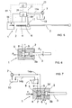
- Fig. 3 is a schematic view of a second percussion device suitable for implementing the method of the invention.
- This embodiment differs from the one above in that pressure fluid is not fed continuously into the working chamber 4, but the pressure fluid pressure is made to act directly on the transmission piston 5 alternately via the working chamber 4 and the return chamber 6.
- the percussion device is pushed forward at a force F S so that a collar 3b' of the tool 3 rests against the body 2 at the same time as the tool 3 is in contact with the material that is the object of the impact, such as rock (not shown) that is to be broken.
- the material that is the object of the impact such as rock (not shown) that is to be broken.
- control valve 8 is used to allow pressure fluid to flow rapidly through the conduit 9' into the working chamber 4, where it acts on the pressure surface of the transmission piston 5 facing away from the tool. At the same time the pressure fluid is allowed to exit from the return chamber 6 through the channel 9.
- the sudden surge of pressurized pressure fluid into the working chamber 4 generates a pressure pulse, the force it produces pushing the transmission piston 5 towards the tool 3 and thereby compressing the tool in the longitudinal direction thereof.
- this allows the length of the clearance d between the tool and the transmission piston to be adjusted, because the return motion of the tool stops, when its collar 3b' comes into contact with the body 2, but the transmission piston is still able to move further backward.
- the length and the pressure of the pressure pulse of the pressure fluid it is possible to adjust the length and intensity of the stress wave.
- the effect of the force generated by pressure and acting on the tool 3 through the transmission piston 5 can be terminated also in other ways than by cutting the supply of pressure fluid into the working chamber 4.
- the movement of the transmission piston 5 can stopped against the collar 2', whereby the pressure acting in the working chamber 4 behind the transmission piston 5 is no longer able to push the piston into the direction of the tool 3 in relation to the body 2.
- Fig. 4 is a schematic graph of the operation of an embodiment of the invention and its energy transfer in a situation, where the clearance between the transmission piston 5 and the tool or between the transmission piston 5 and the transmission piece between the transmission piston 5 and the tool 3 is varied.
- Curve A depicts energy transfer in a situation in which the clearance d is 0 mm. In this case the stress wave is transferred from the transmission piston 5 to the tool entirely in the form of transfer energy.
- the clearance d is 0.2 mm.
- the transmission piston 5 may first move in the tool direction for 0.2 mm without resistance. After less than 0.2 ms, a stress wave is therefore first produced in the tool by the impact of the transmission piston 5 or the transmission piece between the piston and the tool striking the tool.
- Curve C depicts a situation in which the clearance d is 0.4 mm, whereby the transmission piston 5 moves towards the tool for 0.25 ms, most of the energy being transferred to the tool in the form of impact energy and the rest in the form of transfer energy, because the transmission piston 5 and the tool remain in contact with each other for about 0.1 ms.
- Fig. 5 is a schematic view of a third embodiment of a percussion device of the invention. This embodiment relates to a control method of the percussion device of the invention and a basic description of control equipment thereof.
- the control equipment is provided with a control unit 15 controlling the functions of the percussion device.
- reference number 16 denotes feed equipment, which may be any kind of feed equipment known per se for pushing the percussion device 1 forward in the direction of the tool 3.
- Reference numeral 17 denotes a unit for measuring and adjusting the clearance d during the operation of the percussion device.
- reference numeral 18 denotes pressure fluid control valves that may either consist of separate valves or form a single valve configuration.
- the feed device 16, the clearance measurement and adjustment unit 17, and the control valves 18 are connected to the control unit 15 by means of signal channels 19 to 21, depicted with broken lines, which are typically electric conduits.
- the pressure fluid pump 7 and the pressure fluid container 10 are connected to the control valves 18 by channels 14a and 14b, respectively, the control valves 18 being, in turn, provided with pressure fluid channels leading to the feed equipment 16, impact device 1, and clearance measurement and adjustment unit 17. Further, the control unit 15 may be connected to control the pump 7, as shown with a broken line 22.
- sensors provided in the measurement and adjustment unit 17 measure the operation of the percussion device 1 for example by measuring the clearance d and/or the return pulse of the stress wave coming from the tool 3. On the basis of these measurement values, the clearance d is then adjusted as desired according to the drilling conditions.
- the control unit 15 can also be used to control feed and pressure fluid pressure as well as the functions of the percussion device in general either by means of separate manual guides or automatically, on the basis of preset parameters.
- Fig. 6 is yet another view of an embodiment of the percussion device of the invention.
- the essential elements of this embodiment are the cross-sectional surfaces of the transmission piston 5 and the tool.
- This embodiment corresponds to that of Fig. 3 , for example, and therefore it is not considered necessary to repeat the disclosure of the details already described.
- the effective pressure surface of the transmission piston is its cross-sectional surface A pm facing the working chamber.
- the corresponding cross-sectional surface on the tool is Apt.
- Fig. 7 is yet another schematic view of a percussion device suitable for implementing the method of the invention.
- This embodiment corresponds otherwise to the solution of Fig. 3 , except that here the pressure fluid pressure acts in the return chamber 6 all the time during the operation, pressure fluid being alternately fed into and discharged from the working chamber 4 through the control valve 8.
- the force compressing the tool 3 is created as a result of the difference in the surface area between the pressure surfaces, because the surface facing the working chamber 4 is greater than the surface facing the return chamber 6.
- the transmission piston 5 is subject to a force caused by the pressure fluid pressure prevailing in the working chamber 4 and moving it towards the tool 3.
- An aspect of the invention is that stress wave characteristics are adjusted by providing a clearance of a desired size between the transmission piston and the tool so that the tool may be subjected to a stress generated only by compression or to a stress generated only by the kinetic energy caused by an impact, or to a combined form of stress of some kind.
- the various details and solutions of the embodiments illustrated in the different Figures may be combined in various ways for different practical implementations.
Landscapes
- Engineering & Computer Science (AREA)
- Mechanical Engineering (AREA)
- Fluid Mechanics (AREA)
- Physics & Mathematics (AREA)
- Geology (AREA)
- Life Sciences & Earth Sciences (AREA)
- Mining & Mineral Resources (AREA)
- Automation & Control Theory (AREA)
- Environmental & Geological Engineering (AREA)
- General Life Sciences & Earth Sciences (AREA)
- Geochemistry & Mineralogy (AREA)
- Percussive Tools And Related Accessories (AREA)
- Earth Drilling (AREA)
- Apparatuses For Generation Of Mechanical Vibrations (AREA)
Priority Applications (1)
| Application Number | Priority Date | Filing Date | Title |
|---|---|---|---|
| PL06709013T PL1861228T3 (pl) | 2005-03-24 | 2006-03-22 | Urządzenie udarowe |
Applications Claiming Priority (2)
| Application Number | Priority Date | Filing Date | Title |
|---|---|---|---|
| FI20055133A FI117548B (fi) | 2005-03-24 | 2005-03-24 | Iskulaite |
| PCT/FI2006/050109 WO2006100350A1 (en) | 2005-03-24 | 2006-03-22 | Percussion device |
Publications (3)
| Publication Number | Publication Date |
|---|---|
| EP1861228A1 EP1861228A1 (en) | 2007-12-05 |
| EP1861228A4 EP1861228A4 (en) | 2013-04-24 |
| EP1861228B1 true EP1861228B1 (en) | 2014-06-04 |
Family
ID=34385153
Family Applications (1)
| Application Number | Title | Priority Date | Filing Date |
|---|---|---|---|
| EP06709013.4A Not-in-force EP1861228B1 (en) | 2005-03-24 | 2006-03-22 | Percussion device |
Country Status (14)
| Country | Link |
|---|---|
| US (1) | US8061434B2 (ja) |
| EP (1) | EP1861228B1 (ja) |
| JP (1) | JP4898780B2 (ja) |
| KR (1) | KR101182612B1 (ja) |
| CN (1) | CN101146654B (ja) |
| AU (1) | AU2006226277B2 (ja) |
| BR (1) | BRPI0609452A2 (ja) |
| CA (1) | CA2602937C (ja) |
| FI (1) | FI117548B (ja) |
| NO (1) | NO20075341L (ja) |
| PL (1) | PL1861228T3 (ja) |
| RU (1) | RU2386527C2 (ja) |
| WO (1) | WO2006100350A1 (ja) |
| ZA (1) | ZA200707456B (ja) |
Families Citing this family (5)
| Publication number | Priority date | Publication date | Assignee | Title |
|---|---|---|---|---|
| FI123555B (fi) * | 2011-10-06 | 2013-07-15 | Sandvik Mining & Constr Oy | Paineilmatoiminen uppoporakone |
| PL2845989T3 (pl) | 2013-09-09 | 2016-05-31 | Sandvik Intellectual Property | Modyfikacja fali udarowej w aparacie do wiercenia udarowego i sposób |
| PL2905520T3 (pl) | 2014-02-07 | 2017-10-31 | Sandvik Intellectual Property | Zawór regulacji płynu |
| RU2611103C2 (ru) * | 2014-12-24 | 2017-02-21 | Федеральное государственное бюджетное образовательное учреждение высшего образования "Орловский государственный университет имени И.С. Тургенева" (ФГБОУ ВО "ОГУ им. И.С. Тургенева") | Устройство ударного действия |
| CN114166945B (zh) * | 2022-02-14 | 2022-04-12 | 烟台锐铭金属材料有限公司 | 锅炉压力容器检验检测装置 |
Family Cites Families (22)
| Publication number | Priority date | Publication date | Assignee | Title |
|---|---|---|---|---|
| US3662843A (en) * | 1970-01-29 | 1972-05-16 | Gen Dynamics Corp | Impact tools |
| US4006783A (en) * | 1975-03-17 | 1977-02-08 | Linden-Alimak Ab | Hydraulic operated rock drilling apparatus |
| SE7607337L (sv) * | 1976-06-28 | 1977-12-29 | Atlas Copco Ab | Sett och anordning for brytning av ett fast material |
| SE7613107L (sv) * | 1976-11-24 | 1978-05-25 | Atlas Copco Ab | Sett och anordning for brytning av fast material. |
| DE2658455C3 (de) * | 1976-12-23 | 1981-01-22 | Fried. Krupp Gmbh, 4300 Essen | Druckmittelbetriebenes Schlagwerk |
| DE3125454A1 (de) * | 1981-06-29 | 1983-01-20 | Hilti AG, 9494 Schaan | Bohrhammer fuer bohr- und schlagbohrbetrieb |
| JPH0816933B2 (ja) * | 1985-09-25 | 1996-02-21 | カシオ計算機株式会社 | 複数作業の選択起動方法 |
| JPH0432229Y2 (ja) * | 1985-10-24 | 1992-08-03 | ||
| JPS62218081A (ja) * | 1986-03-11 | 1987-09-25 | 浜田 千代 | 油圧式ブレ−カ− |
| US4930584A (en) * | 1989-05-04 | 1990-06-05 | Easy Industries Co., Ltd. | Cracking device |
| JP2759497B2 (ja) * | 1989-05-10 | 1998-05-28 | マツダアステック株式会社 | 打撃工具 |
| JPH02298477A (ja) | 1989-05-10 | 1990-12-10 | Mazda Motor Corp | 打撃工具 |
| FI941689A (fi) * | 1994-04-13 | 1995-10-14 | Doofor Oy | Menetelmä ja poralaite poranterään välitettävän iskupulssin muodon sovittamiseksi |
| FI98401C (fi) * | 1995-10-10 | 1997-06-10 | Tamrock Oy | Menetelmä porakoneen porauksen säätämiseksi ja kallioporakone |
| DE19545708A1 (de) * | 1995-12-07 | 1997-06-12 | Krupp Bautechnik Gmbh | Verfahren zur Beeinflussung des Betriebsverhaltens eines fluidbetriebenen Schlagwerks und zur Durchführung des Verfahrens geeignetes Schlagwerk |
| FI104279B1 (fi) * | 1996-11-27 | 1999-12-15 | Tamrock Oy | Menetelmä ja sovitelma kallionporauksen syötön ohjaamiseksi |
| US6375271B1 (en) * | 1999-04-30 | 2002-04-23 | Young, Iii Chapman | Controlled foam injection method and means for fragmentation of hard compact rock and concrete |
| FI110804B (fi) * | 2000-06-27 | 2003-03-31 | Sandvik Tamrock Oy | Menetelmä porauskomponenttien liitosten avaamiseksi ja kallioporakone |
| FI115553B (fi) * | 2001-05-15 | 2005-05-31 | Sandvik Tamrock Oy | Järjestely porauksen ohjaukseen |
| FI116125B (fi) * | 2001-07-02 | 2005-09-30 | Sandvik Tamrock Oy | Iskulaite |
| FI115037B (fi) * | 2001-10-18 | 2005-02-28 | Sandvik Tamrock Oy | Menetelmä ja sovitelma kallionporauslaitteen yhteydessä |
| FI121218B (fi) * | 2003-07-07 | 2010-08-31 | Sandvik Mining & Constr Oy | Menetelmä jännityspulssin aikaansaamiseksi työkaluun ja painenestekäyttöinen iskulaite |
-
2005
- 2005-03-24 FI FI20055133A patent/FI117548B/fi not_active IP Right Cessation
-
2006
- 2006-03-22 US US11/886,679 patent/US8061434B2/en not_active Expired - Fee Related
- 2006-03-22 WO PCT/FI2006/050109 patent/WO2006100350A1/en active Application Filing
- 2006-03-22 BR BRPI0609452-0A patent/BRPI0609452A2/pt not_active IP Right Cessation
- 2006-03-22 RU RU2007139321/02A patent/RU2386527C2/ru not_active IP Right Cessation
- 2006-03-22 EP EP06709013.4A patent/EP1861228B1/en not_active Not-in-force
- 2006-03-22 CN CN2006800095541A patent/CN101146654B/zh not_active Expired - Fee Related
- 2006-03-22 KR KR1020077024505A patent/KR101182612B1/ko not_active IP Right Cessation
- 2006-03-22 AU AU2006226277A patent/AU2006226277B2/en not_active Ceased
- 2006-03-22 PL PL06709013T patent/PL1861228T3/pl unknown
- 2006-03-22 CA CA2602937A patent/CA2602937C/en not_active Expired - Fee Related
- 2006-03-22 JP JP2008502431A patent/JP4898780B2/ja not_active Expired - Fee Related
-
2007
- 2007-08-31 ZA ZA200707456A patent/ZA200707456B/xx unknown
- 2007-10-18 NO NO20075341A patent/NO20075341L/no not_active Application Discontinuation
Also Published As
| Publication number | Publication date |
|---|---|
| KR101182612B1 (ko) | 2012-09-21 |
| PL1861228T3 (pl) | 2014-09-30 |
| CA2602937A1 (en) | 2006-09-28 |
| US20090025948A1 (en) | 2009-01-29 |
| CN101146654B (zh) | 2010-10-06 |
| FI20055133A0 (fi) | 2005-03-24 |
| RU2007139321A (ru) | 2009-04-27 |
| RU2386527C2 (ru) | 2010-04-20 |
| WO2006100350A1 (en) | 2006-09-28 |
| BRPI0609452A2 (pt) | 2010-04-06 |
| KR20070116657A (ko) | 2007-12-10 |
| AU2006226277B2 (en) | 2011-11-03 |
| US8061434B2 (en) | 2011-11-22 |
| FI20055133A (fi) | 2006-09-25 |
| JP2008534294A (ja) | 2008-08-28 |
| EP1861228A4 (en) | 2013-04-24 |
| JP4898780B2 (ja) | 2012-03-21 |
| CN101146654A (zh) | 2008-03-19 |
| AU2006226277A1 (en) | 2006-09-28 |
| CA2602937C (en) | 2012-09-18 |
| NO20075341L (no) | 2007-10-18 |
| EP1861228A1 (en) | 2007-12-05 |
| FI117548B (fi) | 2006-11-30 |
| ZA200707456B (en) | 2008-10-29 |
Similar Documents
| Publication | Publication Date | Title |
|---|---|---|
| EP1720685B1 (en) | Pressure-fluid-operated percussion device | |
| EP1651391B1 (en) | Impact device and method for generating stress pulse therein | |
| JP4707663B2 (ja) | 作動流体作動式衝撃装置による工具における応力パルス発生方法および衝撃装置。 | |
| EP1861228B1 (en) | Percussion device | |
| EP1539433B1 (en) | Percussion device with an elastic energy storing material | |
| KR101205755B1 (ko) | 압력 유체 작동식 충격 장치 |
Legal Events
| Date | Code | Title | Description |
|---|---|---|---|
| PUAI | Public reference made under article 153(3) epc to a published international application that has entered the european phase |
Free format text: ORIGINAL CODE: 0009012 |
|
| 17P | Request for examination filed |
Effective date: 20070831 |
|
| AK | Designated contracting states |
Kind code of ref document: A1 Designated state(s): AT BE BG CH CY CZ DE DK EE ES FI FR GB GR HU IE IS IT LI LT LU LV MC NL PL PT RO SE SI SK TR |
|
| DAX | Request for extension of the european patent (deleted) | ||
| A4 | Supplementary search report drawn up and despatched |
Effective date: 20130322 |
|
| RIC1 | Information provided on ipc code assigned before grant |
Ipc: E21B 1/26 20060101ALI20130318BHEP Ipc: B25D 9/26 20060101AFI20130318BHEP Ipc: B25D 9/02 20060101ALI20130318BHEP Ipc: E21B 1/32 20060101ALI20130318BHEP Ipc: B25D 9/04 20060101ALI20130318BHEP |
|
| GRAP | Despatch of communication of intention to grant a patent |
Free format text: ORIGINAL CODE: EPIDOSNIGR1 |
|
| INTG | Intention to grant announced |
Effective date: 20140117 |
|
| GRAS | Grant fee paid |
Free format text: ORIGINAL CODE: EPIDOSNIGR3 |
|
| GRAA | (expected) grant |
Free format text: ORIGINAL CODE: 0009210 |
|
| RIN1 | Information on inventor provided before grant (corrected) |
Inventor name: AHOLA, ERKKI Inventor name: KESKINIVA, MARKKU Inventor name: ESKO, MAURI Inventor name: MAEKI, JORMA |
|
| AK | Designated contracting states |
Kind code of ref document: B1 Designated state(s): AT BE BG CH CY CZ DE DK EE ES FI FR GB GR HU IE IS IT LI LT LU LV MC NL PL PT RO SE SI SK TR |
|
| REG | Reference to a national code |
Ref country code: GB Ref legal event code: FG4D |
|
| REG | Reference to a national code |
Ref country code: CH Ref legal event code: EP |
|
| REG | Reference to a national code |
Ref country code: AT Ref legal event code: REF Ref document number: 670791 Country of ref document: AT Kind code of ref document: T Effective date: 20140615 |
|
| REG | Reference to a national code |
Ref country code: IE Ref legal event code: FG4D |
|
| REG | Reference to a national code |
Ref country code: DE Ref legal event code: R096 Ref document number: 602006041774 Country of ref document: DE Effective date: 20140710 |
|
| REG | Reference to a national code |
Ref country code: SE Ref legal event code: TRGR |
|
| REG | Reference to a national code |
Ref country code: PL Ref legal event code: T3 |
|
| REG | Reference to a national code |
Ref country code: AT Ref legal event code: MK05 Ref document number: 670791 Country of ref document: AT Kind code of ref document: T Effective date: 20140604 |
|
| REG | Reference to a national code |
Ref country code: NL Ref legal event code: VDEP Effective date: 20140604 |
|
| PG25 | Lapsed in a contracting state [announced via postgrant information from national office to epo] |
Ref country code: GR Free format text: LAPSE BECAUSE OF FAILURE TO SUBMIT A TRANSLATION OF THE DESCRIPTION OR TO PAY THE FEE WITHIN THE PRESCRIBED TIME-LIMIT Effective date: 20140905 Ref country code: LT Free format text: LAPSE BECAUSE OF FAILURE TO SUBMIT A TRANSLATION OF THE DESCRIPTION OR TO PAY THE FEE WITHIN THE PRESCRIBED TIME-LIMIT Effective date: 20140604 Ref country code: FI Free format text: LAPSE BECAUSE OF FAILURE TO SUBMIT A TRANSLATION OF THE DESCRIPTION OR TO PAY THE FEE WITHIN THE PRESCRIBED TIME-LIMIT Effective date: 20140604 Ref country code: CY Free format text: LAPSE BECAUSE OF FAILURE TO SUBMIT A TRANSLATION OF THE DESCRIPTION OR TO PAY THE FEE WITHIN THE PRESCRIBED TIME-LIMIT Effective date: 20140604 |
|
| REG | Reference to a national code |
Ref country code: LT Ref legal event code: MG4D |
|
| PG25 | Lapsed in a contracting state [announced via postgrant information from national office to epo] |
Ref country code: AT Free format text: LAPSE BECAUSE OF FAILURE TO SUBMIT A TRANSLATION OF THE DESCRIPTION OR TO PAY THE FEE WITHIN THE PRESCRIBED TIME-LIMIT Effective date: 20140604 Ref country code: LV Free format text: LAPSE BECAUSE OF FAILURE TO SUBMIT A TRANSLATION OF THE DESCRIPTION OR TO PAY THE FEE WITHIN THE PRESCRIBED TIME-LIMIT Effective date: 20140604 |
|
| PG25 | Lapsed in a contracting state [announced via postgrant information from national office to epo] |
Ref country code: EE Free format text: LAPSE BECAUSE OF FAILURE TO SUBMIT A TRANSLATION OF THE DESCRIPTION OR TO PAY THE FEE WITHIN THE PRESCRIBED TIME-LIMIT Effective date: 20140604 Ref country code: ES Free format text: LAPSE BECAUSE OF FAILURE TO SUBMIT A TRANSLATION OF THE DESCRIPTION OR TO PAY THE FEE WITHIN THE PRESCRIBED TIME-LIMIT Effective date: 20140604 Ref country code: SK Free format text: LAPSE BECAUSE OF FAILURE TO SUBMIT A TRANSLATION OF THE DESCRIPTION OR TO PAY THE FEE WITHIN THE PRESCRIBED TIME-LIMIT Effective date: 20140604 Ref country code: PT Free format text: LAPSE BECAUSE OF FAILURE TO SUBMIT A TRANSLATION OF THE DESCRIPTION OR TO PAY THE FEE WITHIN THE PRESCRIBED TIME-LIMIT Effective date: 20141006 Ref country code: RO Free format text: LAPSE BECAUSE OF FAILURE TO SUBMIT A TRANSLATION OF THE DESCRIPTION OR TO PAY THE FEE WITHIN THE PRESCRIBED TIME-LIMIT Effective date: 20140604 Ref country code: CZ Free format text: LAPSE BECAUSE OF FAILURE TO SUBMIT A TRANSLATION OF THE DESCRIPTION OR TO PAY THE FEE WITHIN THE PRESCRIBED TIME-LIMIT Effective date: 20140604 |
|
| PG25 | Lapsed in a contracting state [announced via postgrant information from national office to epo] |
Ref country code: NL Free format text: LAPSE BECAUSE OF FAILURE TO SUBMIT A TRANSLATION OF THE DESCRIPTION OR TO PAY THE FEE WITHIN THE PRESCRIBED TIME-LIMIT Effective date: 20140604 Ref country code: IS Free format text: LAPSE BECAUSE OF FAILURE TO SUBMIT A TRANSLATION OF THE DESCRIPTION OR TO PAY THE FEE WITHIN THE PRESCRIBED TIME-LIMIT Effective date: 20141004 |
|
| REG | Reference to a national code |
Ref country code: DE Ref legal event code: R097 Ref document number: 602006041774 Country of ref document: DE |
|
| REG | Reference to a national code |
Ref country code: FR Ref legal event code: PLFP Year of fee payment: 10 |
|
| PLBE | No opposition filed within time limit |
Free format text: ORIGINAL CODE: 0009261 |
|
| STAA | Information on the status of an ep patent application or granted ep patent |
Free format text: STATUS: NO OPPOSITION FILED WITHIN TIME LIMIT |
|
| PG25 | Lapsed in a contracting state [announced via postgrant information from national office to epo] |
Ref country code: IT Free format text: LAPSE BECAUSE OF FAILURE TO SUBMIT A TRANSLATION OF THE DESCRIPTION OR TO PAY THE FEE WITHIN THE PRESCRIBED TIME-LIMIT Effective date: 20140604 Ref country code: DK Free format text: LAPSE BECAUSE OF FAILURE TO SUBMIT A TRANSLATION OF THE DESCRIPTION OR TO PAY THE FEE WITHIN THE PRESCRIBED TIME-LIMIT Effective date: 20140604 |
|
| 26N | No opposition filed |
Effective date: 20150305 |
|
| PGFP | Annual fee paid to national office [announced via postgrant information from national office to epo] |
Ref country code: FR Payment date: 20150309 Year of fee payment: 10 |
|
| REG | Reference to a national code |
Ref country code: DE Ref legal event code: R097 Ref document number: 602006041774 Country of ref document: DE Effective date: 20150305 |
|
| PG25 | Lapsed in a contracting state [announced via postgrant information from national office to epo] |
Ref country code: BE Free format text: LAPSE BECAUSE OF FAILURE TO SUBMIT A TRANSLATION OF THE DESCRIPTION OR TO PAY THE FEE WITHIN THE PRESCRIBED TIME-LIMIT Effective date: 20140604 |
|
| PG25 | Lapsed in a contracting state [announced via postgrant information from national office to epo] |
Ref country code: SI Free format text: LAPSE BECAUSE OF FAILURE TO SUBMIT A TRANSLATION OF THE DESCRIPTION OR TO PAY THE FEE WITHIN THE PRESCRIBED TIME-LIMIT Effective date: 20140604 |
|
| REG | Reference to a national code |
Ref country code: DE Ref legal event code: R119 Ref document number: 602006041774 Country of ref document: DE |
|
| PG25 | Lapsed in a contracting state [announced via postgrant information from national office to epo] |
Ref country code: MC Free format text: LAPSE BECAUSE OF FAILURE TO SUBMIT A TRANSLATION OF THE DESCRIPTION OR TO PAY THE FEE WITHIN THE PRESCRIBED TIME-LIMIT Effective date: 20140604 Ref country code: LU Free format text: LAPSE BECAUSE OF FAILURE TO SUBMIT A TRANSLATION OF THE DESCRIPTION OR TO PAY THE FEE WITHIN THE PRESCRIBED TIME-LIMIT Effective date: 20150322 |
|
| REG | Reference to a national code |
Ref country code: CH Ref legal event code: PL |
|
| GBPC | Gb: european patent ceased through non-payment of renewal fee |
Effective date: 20150322 |
|
| REG | Reference to a national code |
Ref country code: IE Ref legal event code: MM4A |
|
| PG25 | Lapsed in a contracting state [announced via postgrant information from national office to epo] |
Ref country code: DE Free format text: LAPSE BECAUSE OF NON-PAYMENT OF DUE FEES Effective date: 20151001 Ref country code: GB Free format text: LAPSE BECAUSE OF NON-PAYMENT OF DUE FEES Effective date: 20150322 Ref country code: LI Free format text: LAPSE BECAUSE OF NON-PAYMENT OF DUE FEES Effective date: 20150331 Ref country code: IE Free format text: LAPSE BECAUSE OF NON-PAYMENT OF DUE FEES Effective date: 20150322 Ref country code: CH Free format text: LAPSE BECAUSE OF NON-PAYMENT OF DUE FEES Effective date: 20150331 |
|
| PG25 | Lapsed in a contracting state [announced via postgrant information from national office to epo] |
Ref country code: PL Free format text: LAPSE BECAUSE OF NON-PAYMENT OF DUE FEES Effective date: 20150322 |
|
| REG | Reference to a national code |
Ref country code: FR Ref legal event code: ST Effective date: 20161130 |
|
| PG25 | Lapsed in a contracting state [announced via postgrant information from national office to epo] |
Ref country code: FR Free format text: LAPSE BECAUSE OF NON-PAYMENT OF DUE FEES Effective date: 20160331 |
|
| PG25 | Lapsed in a contracting state [announced via postgrant information from national office to epo] |
Ref country code: BG Free format text: LAPSE BECAUSE OF FAILURE TO SUBMIT A TRANSLATION OF THE DESCRIPTION OR TO PAY THE FEE WITHIN THE PRESCRIBED TIME-LIMIT Effective date: 20140604 Ref country code: HU Free format text: LAPSE BECAUSE OF FAILURE TO SUBMIT A TRANSLATION OF THE DESCRIPTION OR TO PAY THE FEE WITHIN THE PRESCRIBED TIME-LIMIT; INVALID AB INITIO Effective date: 20060322 |
|
| PG25 | Lapsed in a contracting state [announced via postgrant information from national office to epo] |
Ref country code: TR Free format text: LAPSE BECAUSE OF FAILURE TO SUBMIT A TRANSLATION OF THE DESCRIPTION OR TO PAY THE FEE WITHIN THE PRESCRIBED TIME-LIMIT Effective date: 20140604 |
|
| PGFP | Annual fee paid to national office [announced via postgrant information from national office to epo] |
Ref country code: SE Payment date: 20200310 Year of fee payment: 15 |
|
| PG25 | Lapsed in a contracting state [announced via postgrant information from national office to epo] |
Ref country code: SE Free format text: LAPSE BECAUSE OF NON-PAYMENT OF DUE FEES Effective date: 20210323 |