EP1860741B1 - Assembly comprising a terminal block for electrical conductors and a removable barrier to be placed against the terminal block - Google Patents
Assembly comprising a terminal block for electrical conductors and a removable barrier to be placed against the terminal block Download PDFInfo
- Publication number
- EP1860741B1 EP1860741B1 EP07107546A EP07107546A EP1860741B1 EP 1860741 B1 EP1860741 B1 EP 1860741B1 EP 07107546 A EP07107546 A EP 07107546A EP 07107546 A EP07107546 A EP 07107546A EP 1860741 B1 EP1860741 B1 EP 1860741B1
- Authority
- EP
- European Patent Office
- Prior art keywords
- conduit
- partition
- opening
- assembly according
- terminal block
- Prior art date
- Legal status (The legal status is an assumption and is not a legal conclusion. Google has not performed a legal analysis and makes no representation as to the accuracy of the status listed.)
- Active
Links
Images


Classifications
-
- H—ELECTRICITY
- H01—ELECTRIC ELEMENTS
- H01R—ELECTRICALLY-CONDUCTIVE CONNECTIONS; STRUCTURAL ASSOCIATIONS OF A PLURALITY OF MUTUALLY-INSULATED ELECTRICAL CONNECTING ELEMENTS; COUPLING DEVICES; CURRENT COLLECTORS
- H01R9/00—Structural associations of a plurality of mutually-insulated electrical connecting elements, e.g. terminal strips or terminal blocks; Terminals or binding posts mounted upon a base or in a case; Bases therefor
- H01R9/22—Bases, e.g. strip, block, panel
- H01R9/24—Terminal blocks
- H01R9/26—Clip-on terminal blocks for side-by-side rail- or strip-mounting
- H01R9/2616—End clamping members
-
- H—ELECTRICITY
- H01—ELECTRIC ELEMENTS
- H01R—ELECTRICALLY-CONDUCTIVE CONNECTIONS; STRUCTURAL ASSOCIATIONS OF A PLURALITY OF MUTUALLY-INSULATED ELECTRICAL CONNECTING ELEMENTS; COUPLING DEVICES; CURRENT COLLECTORS
- H01R13/00—Details of coupling devices of the kinds covered by groups H01R12/70 or H01R24/00 - H01R33/00
- H01R13/46—Bases; Cases
- H01R13/502—Bases; Cases composed of different pieces
Definitions
- the invention relates to terminal blocks for electrical conductors to engage on a rail in ⁇ .
- terminal blocks are used, in particular in the electrical cabinets, to electrically connect two or more electrical conductors together.
- junction blocks comprising an insulating casing having two main faces and several lateral faces connecting the main faces in which are formed several conduits for introducing end portions of electric cables.
- One of the main faces of the housing is closed while the other side is open to allow housing in this housing conductive elements (bar, spring blades or screw terminals) cooperating with the end portions of the cables.
- Terminal partitions are also known, to be disposed against the terminal block, on the side of its open face to completely obscure this face (for example when the terminal block is disposed at the end of a row of terminal blocks on a conductive rail in ⁇ ).
- Partition walls are also known to be arranged between two terminal blocks.
- end or partition walls are formed of a completely solid wall closing all the open spaces on the open main face to isolate the conductive electrical elements disposed within the terminal block.
- DE 20200974-U1 discloses an assembly comprising a terminal block and a removable partition, corresponding to the preamble of claim 1.
- the invention relates to an assembly comprising a terminal block and a partition, both economical and practical to use.
- an assembly comprising a junction block and a removable partition to be arranged against the junction block, said block comprising an insulating casing having two main faces and side faces connecting said main housing faces in which is formed a duct d introduction of the end portion of a cable; characterized in that the introductory conduit has a lateral opening formed on one of the main faces of the housing, said duct and said opening being shaped so that said duct admits the end portion of a cable to a maximum diameter equal to a first predetermined value, said portion of the end of the cable projecting laterally from the duct through said lateral opening of the duct if said diameter is between a second predetermined value less than said first predetermined value and said first predetermined value and in that said partition has an opening which forms an extension of said lateral opening of said conduit, said conduit being open laterally through said opening of said conduit and then through said opening of the partition, said partition and said opening of said partition being shaped so that, if said diameter of the end portion cable is included between ladit e
- the conformation of the introduction duct and the presence of a lateral opening of this duct on one of the main faces makes it possible in particular to install in the terminal block the end portions of electric cables whose largest diameter (the diameter of the element of the end portion of the cable which has the largest dimension) exceeds the pitch of the terminal block, that is to say the distance separating the two parallel main faces of this block (we neglect the thickness, if any, of the wall that closes the duct at the main face of the housing opposite that having the lateral opening), up to a maximum diameter value.
- the end portions of such cables protrude through the lateral opening of the conduit provided for this purpose.
- the partition of the assembly according to the invention is shaped to laterally extend the opening of this conduit so that, when a cable projects from the terminal block through the opening of the conduit, this part of the cable is lodged. in this partition so that it does not exceed the assembly thus formed.
- the conformation of the conduit and its opening together with that of the partition and its opening ensures that even for an end portion of a cable whose largest diameter is equal to the maximum diameter that can be accommodated in the duct, the portion of this cable projecting from the opening of the duct is fully housed in the opening of the partition without protruding from this partition.
- the ducts of this block are shaped to accommodate cables with the largest maximum diameter. is 6 mm, the protruding part of a cable of larger diameter equal to 6 mm (about 1 mm neglecting, if it exists, the thickness of the wall which closes the duct at the level of the main face of the opposite case to that having the lateral opening) being then entirely housed in the partition.
- This set is particularly economical because it allows to use a single type of terminal block for different cable diameters, including those whose largest diameter is greater than the block pitch up to a maximum value.
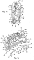
- the terminal block 1 represented in Figures 1 to 12 comprises an insulating housing 2, a conductive bar 3 and two spring blades 4.
- the insulating casing 2 is made of molded plastic and has two main faces 5 and 6 connected to each other by a front lateral face 7, a rear lateral face 8, an upper face 9 and a lower face 10.
- the face 6 is completely obscured by a partition 22 while the face 5 is partially open.
- This housing comprises a latching lug 15, an engagement lug 16 to an ⁇ rail, two cable introduction ducts 32, two operating ducts 33 and a receiving housing 39 (FIG. figure 3 ) of the bar 3 and leaf springs 4.
- the tabs 15 and 16 are located on the side of the face 8. Between these tabs extends a slot 17 formed inside the housing 2 and opening at the face 8.
- the hooking lug 15 has two identical portions 19 on either side of the slot 17, each portion having opposite the locking lug a recess 20 adapted to receive, as will be seen hereinafter a wing of FIG. a rail in ⁇ .
- the latching lug 16 has three partitions 25, 26 and 27 extending substantially transversely to the face 8.
- the partition 25 closest to the latching lug is separated by the slot 17 in two identical portions 18.
- Each portion 18 has a tooth 24 projecting towards the hooking lug 15.
- the housing also comprises between the legs 15 and 16 two partitions 21 on either side of the slot 17 extending parallel to the faces 5 and 6 of the partition portions 19.
- the conduits 32 ( Figures 7 and 8 ) are delimited by two concave surfaces 47 and the surface of a partition 48 located on the side of the face 6 and having a shoulder 48 '.
- the conduits 32 open on the face 7 through an opening 45 and on the face 5 through an opening 43.
- the opening 43 has two parallel edges 43 'in the direction of insertion of the cable and a curved edge 43 ".
- Each duct 32 is closed at the main faces by two triangular partitions 34 projecting parallel to the faces 5 and 6 towards the inside of the housing.
- One of these partitions 34 is located at the partially open face 5 and the other against the wall 22 closing the face 6 of the terminal block ( figure 9 ) locally forming an extra thickness.
- the partition 34 located on the side of the face 6 is extended by a corner 42 ( figure 9 ).
- the conduits 33 have a rectangular section and open only on the face 7 through an opening 46.
- the receiving housing 39 of the bar 3 and the leaf springs 4 is partially delimited by a pair of closed-contour ribs 30 and a pair of closed-contour ribs 31 ( figure 3 ).
- the area of the housing 39 adapted to receive the bar is partially delimited by the rib sections 30 ", 31"'and the lower edge on the figure 3 partitions 34 while each zone of the housing 39 adapted to receive a leaf spring 4 is partially delimited by the rib sections 30 ', 31', 31 "( figure 4 ) and includes space 44 ( figure 7 ) located between the two corresponding partitions 34.
- each zone of the receiving housing 39 adapted to receive a leaf spring 4 is a cylindrical pin 40 and an oblong pin 41.
- the space 44 located between two partitions 34 is common to the corresponding conduit 32 and the housing 39.
- the receiving housing 39 is thus, at each end, partially obscured on the face 5 by a partition 34.
- the casing is molded using three drawers, one for each pair of ducts 32, 33 and a third to form the slot 17.
- the bar 3 comprises a central step 50 ( figure 7 ) and on each side of the central step a side step 51, each side step being connected to the central step by a riser 52 at right angles to the central step 50 and the side steps 51 so that each step 51 forms with its riser 52 a portion in L.
- the side steps 51 are located at the same level relative to each other so that the bar has a podium profile.
- the central step 50 has at its center a single orifice 63 while each side step 51 is provided with a cell 54 delimited by the surfaces of a stamped cage 55 projecting from the opposite side to the central step 50.
- the spring blades 4 represented in Figures 1 to 10 have an asymmetrical V-shaped profile, each leaf spring being formed of a large straight branch 58 and a small straight branch 59 connected to one another at one end by a curved section 60.
- Each of the branches 58 and 59 has, at about mid-length, a width change, with their width being smaller between their free end and the width changing zone.
- This assembly consists first of all in arranging each spring blade 4 in the receiving housing 39.
- the curved section 60 of each leaf spring 4 is arranged around the pin 40 in the space located in the vicinity of this pin on the side opposite the pawn 41 ( figure 3 ).
- the large branch 58 then takes place between the corresponding pins 40, 41 and the corresponding partitions 34 while the small branch 59 takes place between the corresponding pins 40, 41 and the corresponding rib 30 '( figure 3 ).
- the next step is to rotate each leaf spring 4 around the corresponding pin 40, parallel to the faces 5 and 6, so that the end portion of the long section 58 of the spring blade is placed in the space 44 between the partitions 34 ( figure 4 ), this section being guided towards this space by the ramp formed by one of the surfaces of the corner 42 ( figure 9 ), until it stops against the housing ( figure 4 ).
- the end portion of the branch 58 is thus housed in the corresponding introduction conduit 32.
- the blade thus disposed releases the area of the housing 39 adapted to accommodate the bar 3 so that it is now possible to introduce this bar in the housing.
- the central step 50 is arranged between the sections of ribs 30 "and 31 '" of the insulating casing while the end portions of the side steps 51 are housed under the partitions 34 ( figure 5 ).
- the conduit 32 thus opens into the cell 54.
- a wall 56 of the cage 55 is then disposed under the end edge 61 of the branch 58 of the corresponding spring blade while the end portion branch 59 looks, on the side opposite the branch 58, the riser 52 ( Figures 5 and 6 ).
- the last operation consists, using a tool or a rigid core cable through the conduit 32 or 33, to come to exert pressure against the branch 58 to abut the branch 59 against the riser 52 and thus bend the branch 58 to cross a hard point relative to the bar 3 so as to have the end edge 61 of this branch in the cell 54, against the surface 57 of the wall 56 of the cage 55 ( figure 7 ).
- Such tips are for example used in conjunction with cables whose conductive core is formed of flexible strands to facilitate the introduction of conductors in the terminal block without the risk of folding the flexible strands.
- tips (70) comprise a hollow and conductive hollow cylindrical element 71 crimped around the stripped end of a conductor (not shown) and an insulating plastic casing 72.
- the first operation is to penetrate the tip 70 through the conduit 32 in which it must be inserted in order to constrain the leaf spring by pressing the leg 58 to move away the end edge 61 ( figures 6 and 7 ) of the surface 57 to allow this element to pass between this edge 61 and the wall 56.
- the wiring end-piece 70 is thus introduced into the duct 32, the driving movement of the cable continuing for example until the end of the element 71 comes into abutment against the ridge section 31 'or until that the envelope 72 abuts at the level of the face 5 against the curved edge 43 'of the partition 34 or, at the level of the face 6, against the shoulder 48' of the partition 48.
- this wall forms for the element 71 a seat against which it is held by the spring blade 4 which plate against this surface. If this element once installed in the terminal block 1 tends to be removed from the block, that is to say if it is subjected to a force directed in a direction contrary to the direction of insertion, this element will tend to bring with it the branch 58, which will bend and thus wedge against the wall 56, which will prohibit the removal of this element.
- the operator For the withdrawal of the tip 70, the operator makes it through the conduit 33 corresponding to the conduit 32 into which is inserted the nozzle 70, a tool (for example the flat end 73 of the screwdriver shown in FIG. figure 8 ) in order to constrain the leaf spring, until the branch 58 eventually abuts against the oblong pin 41, to release the element 71 and allow to extract the tip 70.
- a tool for example the flat end 73 of the screwdriver shown in FIG. figure 8 ) in order to constrain the leaf spring, until the branch 58 eventually abuts against the oblong pin 41, to release the element 71 and allow to extract the tip 70.
- Such terminal blocks are generally identified by their color, the insulating housing of these blocks being tinted in two colors, one yellow and the other green (green / yellow block).
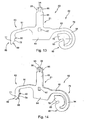
- the contact foot 80 illustrated in Figures 13 and 14 is made of conductive metal and is formed in one piece. It comprises a central body 81, a hooking tab 82, and a locking tab 83.
- the central body 81 has two generally rectangular portions 84 and 85, the portion 84 being wider than the portion 85.
- the portion 84 attaches the tabs 82 and 83 to the rectangular portion 85.
- This portion 85 has at its top two protruding teeth 86 on the side opposite the portion 84 while in the portion 84 is formed a rectangular window 87.
- the locking tab 83 has at its distal end a rigid notch 88 and an elongated and flexible narrow arm 91 attaching the notch 88 to the body 81.
- This notch 88 has a tooth 90 and a finger 77 having a ramp surface 89 and a boss 78.
- the arm 91 is of constant width except for its end portions which are slightly curved, each respectively reaching, by flaring, the notch 88 and the body 81.
- the hooking lug 82 comprises a hook 92 adapted to receive, as will be seen below one of the wings of a rail in ⁇ and an elongated and flexible narrow arm 76 joining the hook 92 to the body 81 by attaching to the hook 92 on the opposite side of the hook 81 to the body relative to the notch 93.
- the arm 76 comprises a C-section 94, here more precisely in a half-circle, in the hollow of which is housed the hook 92 and an inclined straight section 95.
- the C-section 94 is connected at one end to the hook 92 and at the other end to the straight inclined section 95 itself connected by its opposite end to the body 81 so that the arm 76 has a profile in J.
- the hook 92 comprises a rigid block 79 in which is formed a notch V 93.
- the leg of the block 79 defining the notch V located on the side of the hook opposite the body 81 relative to the notch 93 is attached to the arm 94 of the leg 82.
- the contact foot is introduced into the junction block on the side of the face 8 by the slot 17 extending from the latching lug 15 to the latching lug 16 of the insulating housing 2.
- the body 81 enters the insulating housing between the rib portions 31 "", the portion 85 first until a tooth 35 ( figure 11 ) of the insulating housing, protruding from the partition 21 located on the side of the face 5 towards the inside of the housing, is snapped into the square-shaped orifice 87 of the body 81, the slots 23 formed in this partition 21 ensuring an elastic deformation of the tooth 35.
- the hook 92 of the hooking tab 82 of the contact foot is housed between the two partition portions 19 of the tab 15, so that the notch 93 is between the two recesses 20 while the notch 88 of the engagement tab 83 is housed between the two partition portions 18, between the teeth 24 ( figure 11 ).
- the teeth 86 of the foot 80 are arranged in the opening 63 of the step 50 and protrude with respect to the bar towards the face 7 ( figure 11 ).
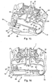
- a crimping operation is performed using a tool (not shown) adapted to be introduced into the housing on the side of the face 7 by two chimneys 37 ( figure 10 ) formed in the insulating housing on each side of a central wall 38 and opening on the face 7 to exert pressure against the surfaces 96 of the teeth 86 to move them away from each other as illustrated in FIG. figure 10 .
- This crimping makes it possible to guarantee the permanent mechanical maintenance of the contact foot 80 with the bar 3 and improves, by increasing the clamping pressure with this bar, the quality of the electrical contact between this foot and this bar.
- the engagement of the terminal block is here described in the case where it has a contact foot.
- the interlocking characteristics of the insulating housing alone remain the same when the terminal block does not have such a contact foot (no electrical connection to the rail).
- the conductive support rail 65 shown on the Figures 15 to 18 is a profile rail commonly used to install terminal blocks. It has a central section 66 and two branches 67 folded at right angles, the ends of the branches 67 being bent at right angles outwards to form two wings side 68, the section of the profile rail thus having a shape in ⁇ (reversed in the figures).
- This rail can be fixed (for example by screwing the portion 66) to the uprights of an electrical cabinet or against a wall support, the central section 66 and the wings 68 then being in a vertical plane (rotated 90 ° relative to the Figures 17 and 18 ).
- the interlocking operation consists of hooking the terminal block against one of the wings 68 of the ⁇ rail as illustrated in FIG. figure 15 by introducing this wing into the notch 93 of the hooking tab 82 of the contact foot (shown without the insulating housing in figure 17 for the sake of clarity) as well as in the recess 20 of the attachment lug 15 of the insulating housing ( figure 15 ).
- the next step is to simultaneously engage the interlocking tab 83 ( figure 18 ) of the contact foot and the locking tab 16 ( figure 16 ) of the insulating housing on the other flange 68 of the ⁇ rail.
- the operator presses the terminal block against the face 7 towards the rail in ⁇ and preferably, to take advantage of the leverage, the farthest side of the tab 15.
- This action causes a deformation of the arm 82 until the engagement tab 83 is supported by the ramp 89 of the finger 77 against the upper edge of the wing 68 corresponding.
- the ramp 89 thus guides the foot 80 which deforms until this ramp passes under the wing 68, the tooth 90 abutting against this wing ( figure 18 ).
- the boss 78 located at the end of the ramp 89, under the tooth 90 ensures the stable maintenance of the contact foot rail, preventing any risk of inadvertent disengagement.
- the long length of the sections 94 and 95 ensures optimum flexibility for the arm 76 which deforms throughout this operation.
- the engagement lug 16 of the insulating housing engages in a similar manner on the same flange, each tooth 24 being supported by its curved surface 28 ( figure 15 ) against the upper edge of the corresponding flange 68 to guide the flap 16.
- the partitions 25 to 27 of this tab slightly deform transversely to the rail so that each tooth 24 engages and closes under this wing by elastic return ( figure 16 ).
- a connection to the ⁇ rail is made in the same way except that such a terminal block is engaged to the rail only by the legs of the rail. hooking and engagement of the insulating housing. Such an operation then in this case not to provide an electrical connection but only to ensure mechanical support of the terminal block to the rail.
- the rail 165 represented in figure 19 and the rail 265 shown in figure 20 differ from the rail 65 represented in figure 17 especially by the height and thickness of their branches and their wings.
- the V-shaped notch 93 and in particular the distance to the bottom of the notch separating the two branches of the V is adapted to cooperate with the three types of rail illustrated, that the wings of these rails is of constant thickness ( rail 65) or that this thickness decreases towards the edge of the wings (rails 165 and 265).
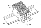
- This partition 97 ( Figures 21 to 23 ) has two notches 99, two pins 98 and two ribs 96 projecting from the same side of the partition 97.
- Each notch 99 has a contour similar to that of the opening 43 of the conduit 32 corresponding. Each notch is thus delimited by two straight edges 99 'parallel to the direction of insertion of the cable and an edge 99 "transverse to this direction joining the straight edges 99'.
- This partition is nested at the junction block 1 by disposing the partition 97 facing the face 5 of the junction block 1 so that the lugs 98 of this partition are engaged in mortises 29 that presents the insulating housing 1 of the block of junction ( figure 22 ), the rib 96 then being housed within the rib 31 to increase the length of the vanishing lines of the terminal block.
- each duct 32 of the terminal block has an opening 43 through which a wiring end can project laterally, in particular if the largest diameter of this endpiece is greater than the distance separating the main faces 5 and 6 (also called step of the terminal block), neglecting the thickness of the partition 48 closing the conduit 32 at the face 6.
- the thickness of the partition 48 is relatively small so that it is considered that it is a negligible magnitude before the pitch of the terminal block.
- larger diameter is used here to mean that of the diameters of the element of the endpiece which has the largest dimension, for example, in the case of the endpiece 70, the diameter of the envelope 72.
- each terminal block then come to bear, by its face 6 not against the protruding portion of the cable end received in the adjacent terminal block but against the partition 97 of this neighboring block.
- the convex faces 47, the partition 48 and the shoulder 48 'and the edges 43' and 43 are dimensioned together with the partition 97 to ensure that, even for a wiring end having a larger diameter equal to the diameter. maximum that can be received in the conduit, the portion of this nozzle projecting from the block through the opening 43 of the conduit can be fully housed in the opening 99 of the partition 97 without protruding from this partition.
- the junction block has a pitch of 5 mm and the ducts 32 are adapted to receive wiring nozzles of greater maximum diameter equal to 6 mm, while the partition 97 has a thickness of 1 mm so as to accommodate in each aperture 99 the portions of the end pieces projecting from the block and up to the maximum diameter of 6 mm (ie a maximum lateral projection of about 1 mm with respect to the terminal block).
- a tip of larger diameter greater than 6 mm can not be introduced into the ducts 32, these ducts being shaped so that such an endpiece abuts against the edges of the opening 45 and thus prevent its insertion.
- the terminal block is designed to receive not two but at least three conductors arranged on one or more stages of the terminal block.
Abstract
Description
L'invention a trait aux blocs de jonction pour conducteurs électriques à engager sur un rail en Ω.The invention relates to terminal blocks for electrical conductors to engage on a rail in Ω.
On sait que de tels blocs de jonction sont utilisés, notamment dans les armoires électriques, afin de relier électriquement entre eux deux conducteurs électriques ou plus.It is known that such terminal blocks are used, in particular in the electrical cabinets, to electrically connect two or more electrical conductors together.
On connaît déjà des blocs de jonctions comportant un boîtier isolant présentant deux faces principales et plusieurs faces latérales reliant les faces principales dans lequel sont ménagés plusieurs conduits d'introduction de portions d'extrémité de câbles électriques.Junction blocks are already known comprising an insulating casing having two main faces and several lateral faces connecting the main faces in which are formed several conduits for introducing end portions of electric cables.
L'une des faces principales du boîtier est fermée tandis que l'autre face est ouverte pour permettre de loger dans ce boîtier les éléments conducteurs (barrette, lames ressort ou bornes à vis) coopérant avec les portions d'extrémité des câbles.One of the main faces of the housing is closed while the other side is open to allow housing in this housing conductive elements (bar, spring blades or screw terminals) cooperating with the end portions of the cables.
On connaît également des cloisons terminales, à disposer contre le bloc de jonction, du côté de sa face ouverte pour entièrement occulter cette face (par exemple lorsque le bloc de jonction est disposé au bout d'une rangée de blocs de jonction sur un rail conducteur en Ω).Terminal partitions are also known, to be disposed against the terminal block, on the side of its open face to completely obscure this face (for example when the terminal block is disposed at the end of a row of terminal blocks on a conductive rail in Ω).
On connaît également des cloisons de séparation à disposer entre deux blocs de jonction.Partition walls are also known to be arranged between two terminal blocks.
Ces cloisons terminales ou de séparation sont formées d'une paroi entièrement pleine obturant l'ensemble des espaces ouverts sur la face principale ouverte afin d'isoler les éléments électriques conducteurs disposés au sein du bloc de jonction.These end or partition walls are formed of a completely solid wall closing all the open spaces on the open main face to isolate the conductive electrical elements disposed within the terminal block.
L'invention vise un ensemble comportant un bloc de jonction et une cloison, à la fois économique et pratique à l'utilisation.The invention relates to an assembly comprising a terminal block and a partition, both economical and practical to use.
Elle propose à cet effet un ensemble comportant un bloc de jonction et une cloison amovible à disposer contre le bloc de jonction, ledit bloc comportant un boîtier isolant présentant deux faces principales et des faces latérales reliant lesdites faces principales boîtier dans lequel est ménagé un conduit d'introduction de la portion d'extrémité d'un câble ; caractérisé en ce que le conduit d'introduction présente une ouverture latérale ménagée sur une des faces principales du boîtier, ledit conduit et ladite ouverture étant conformés pour que ledit conduit admette la portion d'extrémité d'un câble jusqu'à un diamètre maximal égal à une première valeur prédéterminée, ladite portion d'extrémité du câble faisant saillie latéralement du conduit par ladite ouverture latérale du conduit si ledit diamètre est compris entre une seconde valeur prédéterminée inférieure à ladite première valeur prédéterminée et ladite première valeur prédéterminée et en ce que ladite cloison présente une ouverture qui forme une extension de ladite ouverture latérale dudit conduit, ledit conduit étant ouvert latéralement au travers de ladite ouverture dudit conduit puis au travers de ladite ouverture de la cloison, ladite cloison et ladite ouverture de ladite cloison étant conformés pour que, si ledit diamètre de la portion d'extrémité du câble est compris entre ladite seconde valeur prédéterminée et ladite première valeur prédéterminée, ladite portion d'extrémité faisant saillie latéralement du conduit par ladite ouverture latérale du conduit se loge entièrement dans l'espace délimité par l'ouverture de ladite cloison.It proposes for this purpose an assembly comprising a junction block and a removable partition to be arranged against the junction block, said block comprising an insulating casing having two main faces and side faces connecting said main housing faces in which is formed a duct d introduction of the end portion of a cable; characterized in that the introductory conduit has a lateral opening formed on one of the main faces of the housing, said duct and said opening being shaped so that said duct admits the end portion of a cable to a maximum diameter equal to a first predetermined value, said portion of the end of the cable projecting laterally from the duct through said lateral opening of the duct if said diameter is between a second predetermined value less than said first predetermined value and said first predetermined value and in that said partition has an opening which forms an extension of said lateral opening of said conduit, said conduit being open laterally through said opening of said conduit and then through said opening of the partition, said partition and said opening of said partition being shaped so that, if said diameter of the end portion cable is included between ladit e second predetermined value and said first predetermined value, said end portion projecting laterally from the duct by said lateral opening of the duct is entirely housed in the space delimited by the opening of said partition.
La conformation du conduit d'introduction et la présence d'une ouverture latérale de ce conduit sur l'une des faces principales permet en particulier d'installer dans le bloc de jonction les portions d'extrémité de câbles électriques dont le plus grand diamètre (le diamètre de l'élément de la portion d'extrémité du câble qui présente la plus grande dimension) excède le pas du bloc de jonction, c'est-à-dire la distance séparant les deux faces principales parallèles de ce bloc (on néglige l'épaisseur, si elle existe, de la paroi qui ferme le conduit au niveau de la face principale du boîtier opposée à celle présentant l'ouverture latérale), jusqu'à une valeur de diamètre maximale. Les portions d'extrémité de tels câbles font saillie par l'ouverture latérale du conduit ménagée à cet effet.The conformation of the introduction duct and the presence of a lateral opening of this duct on one of the main faces makes it possible in particular to install in the terminal block the end portions of electric cables whose largest diameter ( the diameter of the element of the end portion of the cable which has the largest dimension) exceeds the pitch of the terminal block, that is to say the distance separating the two parallel main faces of this block (we neglect the thickness, if any, of the wall that closes the duct at the main face of the housing opposite that having the lateral opening), up to a maximum diameter value. The end portions of such cables protrude through the lateral opening of the conduit provided for this purpose.
De plus la cloison de l'ensemble selon l'invention est conformée pour prolonger latéralement l'ouverture de ce conduit de sorte que, lorsqu'un câble fait saillie du bloc de jonction par l'ouverture du conduit, cette partie du câble se loge dans cette cloison si bien que celle-ci ne dépasse pas de l'ensemble ainsi formé.In addition, the partition of the assembly according to the invention is shaped to laterally extend the opening of this conduit so that, when a cable projects from the terminal block through the opening of the conduit, this part of the cable is lodged. in this partition so that it does not exceed the assembly thus formed.
En conséquence, si un second bloc de jonction est à disposer contre celui qui accueille un tel câble (pour réaliser un alignement de blocs de jonction engagés sur un rail en Ω par exemple), le second bloc de jonction n'est pas gêné par ce câble puisque ce second bloc vient dans ce cas prendre appui non pas contre la partie du câble qui aurait fait saillie sans la cloison ajoutée mais contre cette cloison justement.Consequently, if a second terminal block is to be arranged against the one accommodating such a cable (to perform an alignment of terminal blocks engaged on a rail in Ω for example), the second terminal block is not bothered by this. cable since this second block comes in this case take support not against the part of the cable that would have protruded without the partition added but against this partition precisely.
Le fait que l'ouverture du conduit soit prolongée par une ouverture traversant entièrement la cloison permet d'offrir un maximum d'espace dans la cloison aux parties saillantes des câbles pouvant être reçus dans le conduit.The fact that the opening of the conduit is extended by an opening completely through the partition allows to offer maximum space in the partition to the projections of the cables that can be received in the conduit.
De plus, la conformation du conduit et de son ouverture conjointement avec celle de la cloison et de son ouverture permet de garantir que même pour une portion d'extrémité d'un câble dont le plus grand diamètre est égal au diamètre maximal pouvant être reçu dans le conduit, la partie de ce câble faisant saillie de l'ouverture du conduit est entièrement logée dans l'ouverture de la cloison sans faire saillie de cette cloison.In addition, the conformation of the conduit and its opening together with that of the partition and its opening ensures that even for an end portion of a cable whose largest diameter is equal to the maximum diameter that can be accommodated in the duct, the portion of this cable projecting from the opening of the duct is fully housed in the opening of the partition without protruding from this partition.
Ainsi par exemple, si l'on choisit une épaisseur de 1 mm pour la cloison selon l'invention et un pas de 5 mm pour le bloc de jonction, les conduits de ce bloc sont conformés pour accueillir des câbles dont le plus grand diamètre maximal est de 6 mm, la partie saillante d'un câble de plus grand diamètre égal à 6 mm (environ 1 mm en négligeant, si elle existe, l'épaisseur de la paroi qui ferme le conduit au niveau de la face principale du boîtier opposée à celle présentant l'ouverture latérale) étant alors entièrement logée dans la cloison.For example, if a thickness of 1 mm is chosen for the partition according to the invention and a pitch of 5 mm for the terminal block, the ducts of this block are shaped to accommodate cables with the largest maximum diameter. is 6 mm, the protruding part of a cable of larger diameter equal to 6 mm (about 1 mm neglecting, if it exists, the thickness of the wall which closes the duct at the level of the main face of the opposite case to that having the lateral opening) being then entirely housed in the partition.
Cet ensemble est ainsi particulièrement économique car il permet d'utiliser un seul type de bloc de jonction pour différents diamètres de câble, y compris ceux dont le plus grand diamètre est supérieur au pas du bloc jusqu'à une valeur maximale.This set is particularly economical because it allows to use a single type of terminal block for different cable diameters, including those whose largest diameter is greater than the block pitch up to a maximum value.
Selon des caractéristiques préférées, pour des raisons de simplicité, de commodité et d'économie de mise en oeuvre :
- ladite ouverture dudit conduit est délimitée par deux bords droits sensiblement parallèles à la direction longitudinale du conduit ;
- la distance séparant lesdits bords droits est inférieure à ladite première valeur prédéterminée ;
- lesdits bords parallèles sont joints l'un à l'autre par un bord transversal à la direction longitudinale du conduit ;
- ledit bord transversal est incurvé ;
- ledit bord transversal est le bord d'une cloison fermant partiellement latéralement ledit conduit au niveau de ladite face principale sur laquelle est ménagée ladite ouverture latérale ;
- ledit conduit est fermé latéralement par une cloison au niveau de la face principale opposée à celle présentant ladite ouverture latérale ;
- ladite cloison présente un épaulement en saillie vers l'intérieur du boîtier :
- ledit conduit présente deux surfaces concaves en regard l'une de l'autre ;
- la distance maximale séparant lesdites surfaces concaves est sensiblement égale à ladite première valeur prédéterminée, chaque dite surface concave présentant le même contour que la surface convexe de la portion d'extrémité d'un câble de diamètre égal à ladite première valeur prédéterminée ;
- l'ouverture de ladite cloison présente un contour semblable à celui de l'ouverture dudit conduit;
- ladite cloison présente au moins un tenon saillant adapté à être engagé dans une mortaise que comporte ledit boîtier isolant ; et/ou
- ladite cloison présente une épaisseur d'au moins 1 mm.
- said opening of said duct is delimited by two straight edges substantially parallel to the longitudinal direction of the duct;
- the distance between said right edges is less than said first predetermined value;
- said parallel edges are joined to each other by an edge transverse to the longitudinal direction of the conduit;
- said transverse edge is curved;
- said transverse edge is the edge of a partition partially closing laterally said duct at said main face on which is formed said lateral opening;
- said duct is closed laterally by a partition at the main face opposite to that having said lateral opening;
- said partition has a shoulder projecting towards the inside of the housing:
- said duct has two concave surfaces facing each other;
- the maximum distance separating said concave surfaces is substantially equal to said first predetermined value, each said concave surface having the same contour as the convex surface of the end portion of a cable of diameter equal to said first predetermined value;
- the opening of said partition has a contour similar to that of the opening of said duct;
- said partition has at least one projecting pin adapted to be engaged in a mortise that includes said insulating housing; and or
- said partition has a thickness of at least 1 mm.
L'exposé de l'invention sera maintenant poursuivi par la description détaillée d'un exemple de réalisation, donnée ci-après à titre illustratif et non limitatif, en référence aux dessins annexés. Sur ceux-ci :
- la
figure 1 est une vue en perspective d'un bloc de jonction dans lequel ont été insérés des embouts de câblage de diamètres différents ; - la
figure 2 est une vue en élévation de ce bloc de jonction prise de devant sur lafigure 1 mais sans que les embouts de câblage n'aient été introduits dans ce bloc ; - les
figures 3 à 5 sont trois vues en élévation similaires à lafigure 2 présentant les différentes opérations d'assemblage de lames ressort et d'une barrette conductrice que comporte ce bloc de jonction ; - les
figures 6 et7 sont deux vues en élévation-coupe selon un plan parallèle et centré par rapport aux faces principales du bloc de jonction prises respectivement avant et après que l'une des branches de chacune des lames ressort assemblées n'ait été engagée dans une alvéole correspondante ménagée dans la barrette ; - la
figure 8 est une vue similaire à lafigure 1 mais prise sous un angle différent et illustrant l'opération de retrait d'un embout de câblage à l'aide de l'extrémité plate d'un tournevis ; - la
figure 9 est une vue agrandie du détail repéré par IX sur lafigure 8 ; - la
figure 10 est une vue en élévation-coupe d'un bloc de jonction semblable à celui représenté sur lesfigures 1 à 9 auquel a été ajouté un pied de contact à mettre en liaison électrique avec un rail conducteur en Ω ; - la
figure 11 est une vue en élévation-coupe de ce bloc prise selon un plan perpendiculaire et centré par rapport aux faces principales du bloc de jonction ; - la
figure 12 est une vue en perspective illustrant l'opération d'assemblage de ce pied de contact au bloc de jonction ; - les
figures 13 et 14 sont respectivement une vue en élévation et une vue en perspective représentant isolément ce pied de contact ; - les
figures 15 et 16 sont deux vues en perspective du bloc de jonction muni du pied de contact illustré enfigures 10 à 14 , respectivement prises avant et après l'opération d'enclenchement de ce bloc au rail en Ω ; - les
figures 17 et 18 sont deux vues similaires auxfigures 15 et 16 mais sans que ne soit représenté le boîtier isolant que comporte ce bloc de jonction ; - les
figures 19 et 20 sont deux vues similaires à lafigure 17 , mais sans que ne soit représenté la barrette et les lames ressort, pour deux variantes du rail en Ω représenté enfigures 17 et 18 ; - la
figure 21 est une vue en perspective représentant un ensemble constitué d'un bloc de jonction représenté enfigures 1 à 9 , dans lequel ont été insérés des embouts de câblage de diamètres différents, et d'une cloison amovible emboîtée dans ce bloc ; - la
figure 22 est une vue représentant cette cloison et ce bloc de jonction détachés l'un de l'autre ; et - la
figure 23 est une vue en perspective d'une série d'ensembles formés chacun d'un bloc de jonction et d'une cloison disposés les uns contre les autres sur un rail en Ω.
- the
figure 1 is a perspective view of a terminal block into which cable ends of different diameters have been inserted; - the
figure 2 is an elevational view of this junction block taken from the front on thefigure 1 but without the wiring ends being introduced into this block; - the
Figures 3 to 5 are three elevational views similar to thefigure 2 presenting the various spring blade assembly operations and a conductive bar that includes this junction block; - the
figures 6 and7 are two views in elevation-section along a plane parallel and centered with respect to the main faces of the terminal block taken respectively before and after one of the branches of each of the blades assembled spring has been engaged in a corresponding cell formed in the bar; - the
figure 8 is a view similar to thefigure 1 but taken at a different angle and illustrating the operation of removing a cable end using the flat end of a screwdriver; - the
figure 9 is an enlarged view of the detail spotted by IX on thefigure 8 ; - the
figure 10 is an elevational sectional view of a terminal block similar to that shown on theFigures 1 to 9 to which has been added a contact foot to be electrically connected to a conducting rail in Ω; - the
figure 11 is a sectional elevation view of this block taken along a plane perpendicular and centered with respect to the main faces of the terminal block; - the
figure 12 is a perspective view illustrating the assembly operation of this contact foot at the terminal block; - the
Figures 13 and 14 are respectively an elevational view and a perspective view showing in isolation this contact foot; - the
Figures 15 and 16 are two perspective views of the terminal block with the contact foot illustrated inFigures 10 to 14 respectively taken before and after the engagement operation of this block to the rail in Ω; - the
Figures 17 and 18 are two similar views toFigures 15 and 16 but without being represented the insulating housing that includes this terminal block; - the
Figures 19 and 20 are two views similar to thefigure 17 , but without being represented the bar and the leaf spring, for two variants of the rail in Ω represented inFigures 17 and 18 ; - the
figure 21 is a perspective view showing an assembly consisting of a terminal block shown in FIG.Figures 1 to 9 , in which were inserted the wiring ends of different diameters, and a removable partition nested in this block; - the
figure 22 is a view representing this partition and this terminal block detached from each other; and - the
figure 23 is a perspective view of a series of assemblies each formed of a terminal block and a partition disposed against each other on a Ω rail.
Le bloc de jonction 1 représenté en
Le boîtier isolant 2 est en matière plastique moulée et présente deux faces principales 5 et 6 reliées l'une à l'autre par une face latérale avant 7, une face latérale arrière 8, une face haute 9 et une face basse 10.The insulating
La face 6 est entièrement occultée par une cloison 22 tandis que la face 5 est partiellement ouverte.The
Ce boîtier comporte un patte d'accrochage 15, une patte d'enclenchement 16 à un rail en Ω, deux conduits d'introduction de câbles 32, deux conduits de manoeuvre 33 et un logement d'accueil 39 (
Les pattes 15 et 16 sont situées du côté de la face 8. Entre ces pattes s'étend une fente 17 ménagée à l'intérieur du boîtier 2 et débouchant au niveau de la face 8.The
La patte d'accrochage 15 comporte deux portions identiques 19 de part et d'autre de la fente 17, chaque portion présentant en regard de la patte d'enclenchement un renfoncement 20 adapté à recevoir comme on le verra ci-après une aile d'un rail en Ω.The hooking
La patte d'enclenchement 16 présente trois cloisons 25, 26 et 27 s'étendant sensiblement transversalement à la face 8. La cloison 25 la plus proche de la patte d'accrochage est séparée par la fente 17 en deux portions identiques 18. Chaque portion 18 présente une dent 24 en saillie vers la patte d'accrochage 15.The latching
Le boîtier comporte également entre les pattes 15 et 16 deux cloisons 21 de part et d'autre de la fente 17 prolongeant parallèlement aux faces 5 et 6 les portions de cloison 19.The housing also comprises between the
Les conduits 32 (
L'ouverture 43 présente deux bords parallèles 43' selon la direction d'insertion du câble et un bord incurvé 43".The
Chaque conduit 32 est fermé au niveau des faces principales par deux cloisons triangulaires 34 saillantes parallèlement aux faces 5 et 6 vers l'intérieur du boîtier.Each
L'une de ces cloisons 34 est située au niveau de la face partiellement ouverte 5 et l'autre contre la paroi 22 fermant la face 6 du bloc de jonction (
La cloison 34 située du coté de la face 6 se prolonge par un coin 42 (
Les conduits 33 présentent une section rectangulaire et débouchent uniquement sur la face 7 par une ouverture 46.The
Le logement d'accueil 39 de la barrette 3 et des lames ressorts 4 est partiellement délimité par une paire de nervures à contour fermé 30 et une paire de nervures à contour fermé 31 (
La zone du logement 39 adaptée à recevoir la barrette est partiellement délimitée par les tronçons de nervure 30", 31 "', et le bord inférieur sur la
Dans chaque zone du logement d'accueil 39 adaptée à recevoir une lame ressort 4 se situe un pion cylindrique 40 et un pion oblong 41.In each zone of the receiving
A chaque extrémité, l'espace 44 situé entre deux cloisons 34 est commun au conduit 32 correspondant et au logement 39. Le logement d'accueil 39 est ainsi, à chaque extrémité, partiellement occulté sur la face 5 par une cloison 34.At each end, the
Le moulage du boîtier est obtenu à l'aide de trois tiroirs, un pour chaque paire de conduits 32, 33 et un troisième pour former la fente 17.The casing is molded using three drawers, one for each pair of
On va maintenant décrire la barrette 3 et les lames ressorts 4 à l'aide des
La barrette 3 comporte une marche centrale 50 (
Les marches latérales 51 sont situées au même niveau l'une par rapport à l'autre de sorte que la barrette présente un profil en podium.The side steps 51 are located at the same level relative to each other so that the bar has a podium profile.
La marche centrale 50 présente en son centre un unique orifice 63 tandis que chaque marche latérale 51 est munie d'une alvéole 54 délimitée par les surfaces d'une cage emboutie 55 saillant du côté opposé à la marche centrale 50.The
Les lames ressort 4 représentées en
Chacune des branches 58 et 59 présente, à peu près à mi-longueur, un changement de largeur, avec leur largeur qui est plus petite entre leur extrémité libre et la zone de changement de largeur.Each of the
On va maintenant décrire l'opération d'assemblage du bloc de jonction à l'aide des
Cet assemblage consiste dans un premier temps à disposer chaque lame ressort 4 dans le logement d'accueil 39. Le tronçon recourbé 60 de chaque lame ressort 4 est disposé autour du pion 40 dans l'espace situé au voisinage de ce pion du côté opposé au pion 41 (
L'étape suivante consiste à faire pivoter chaque lame ressort 4 autour du pion 40 correspondant, parallèlement aux faces 5 et 6, de sorte que la portion d'extrémité du tronçon de grande longueur 58 de la lame ressort se place dans l'espace 44 entre les cloisons 34 (
La portion d'extrémité de la branche 58 est ainsi logée dans le conduit d'introduction 32 correspondant.The end portion of the
La lame ainsi disposée libère alors la zone du logement 39 adaptée à accueillir la barrette 3 de sorte qu'il est désormais possible d'introduire cette barrette dans le boîtier.The blade thus disposed releases the area of the
Au cours de cette introduction, la marche centrale 50 est disposée entre les tronçons de nervures 30" et 31'" du boîtier isolant tandis que les portions d'extrémité des marches latérales 51 se logent sous les cloisons 34 (
Pour chaque cage 55, le conduit 32 débouche ainsi dans l'alvéole 54. Une paroi 56 de la cage 55 est alors disposée sous l'arête d'extrémité 61 de la branche 58 de la lame ressort correspondante tandis que la portion d'extrémité de la branche 59 regarde, du côté opposé à la branche 58, la contremarche 52 (
La dernière opération consiste, à l'aide d'un outil ou d'un câble à âme rigide au travers du conduit 32 ou 33, à venir exercer une pression contre la branche 58 pour faire venir en butée la branche 59 contre la contremarche 52 et ainsi faire fléchir la branche 58 afin de franchir un point dur par rapport à la barrette 3 de façon à disposer l'arête d'extrémité 61 de cette branche dans l'alvéole 54, contre la surface 57 de la paroi 56 de la cage 55 (
Dans cette position, la barrette est retenue en direction de la face 5 par la portion d'extrémité de la branche 58 de lame ressort engagée dans la cage 55, cette même branche étant retenue par la cloison 34 située au niveau de cette face 5, la lame ressort 4 étant maintenue en position grâce à la contremarche 52 contre laquelle vient en butée la portion d'extrémité de la branche 59.In this position, the bar is retained in the direction of the
On va maintenant décrire l'opération d'introduction d'un embout de câblage dans le bloc de jonction 1 à l'aide de la
De tels embouts sont par exemple utilisés en conjonction avec des câbles dont l'âme conductrice est formée de brins souples pour faciliter l'introduction des conducteurs dans le bloc de jonction sans risque de faire plier les brins souples.Such tips are for example used in conjunction with cables whose conductive core is formed of flexible strands to facilitate the introduction of conductors in the terminal block without the risk of folding the flexible strands.
Ces embouts (70) comportent un élément cylindrique creux conducteur et rigide 71 serti autour de l'extrémité dénudée d'un conducteur (non représenté) et une enveloppe en matière plastique isolante 72.These tips (70) comprise a hollow and conductive hollow
La première opération consiste à faire pénétrer l'embout 70 au travers du conduit 32 dans lequel il doit être inséré afin de contraindre la lame ressort en appuyant sur la branche 58 pour écarter l'arête d'extrémité 61 (
Aucun mouvement de rotation de la lame ressort 4 n'est possible puisque la branche 59 de cette lame est maintenue au cours de cet effort en butée contre la contremarche 52.No rotational movement of the
L'embout de câblage 70 est ainsi introduit dans le conduit 32, le mouvement d'enfoncement du câble se poursuivant par exemple jusqu'à ce que le bout de l'élément 71 vienne en butée contre le tronçon de nervure 31' ou jusqu'à ce que l'enveloppe 72 vienne en butée au niveau de la face 5 contre le bord incurvé 43' de la cloison 34 ou, au niveau de la face 6, contre l'épaulement 48' de la cloison 48.The wiring end-
La surface interne 57 de cette paroi forme pour l'élément 71 un siège contre lequel il est maintenu par la lame ressort 4 qui le plaque contre cette surface. Si cet élément une fois installé dans le bloc de jonction 1 tend à être retiré du bloc, c'est-à-dire s'il est soumis à un effort dirigé dans un sens contraire au sens d'insertion, cet élément aura tendance à entraîner avec lui la branche 58, qui va s'arc-bouter et donc le coincer contre la paroi 56, ce qui interdira le retrait de cet élément.The
Pour le retrait de l'embout 70, l'opérateur fait pénétrer au travers du conduit 33 correspondant au conduit 32 dans lequel est inséré l'embout 70, un outil (par exemple l'extrémité plate 73 du tournevis représenté en
On va maintenant décrire à l'aide des
De tels blocs de jonction sont en général identifiés par leur couleur, le boîtier isolant de ces blocs étant teinté en deux couleurs l'une jaune et l'autre verte (bloc vert/jaune).Such terminal blocks are generally identified by their color, the insulating housing of these blocks being tinted in two colors, one yellow and the other green (green / yellow block).
Le pied de contact 80 illustré en
Le corps central 81 comporte deux portions globalement rectangulaires 84 et 85, la portion 84 étant plus large que la portion 85. La portion 84 rattache les pattes 82 et 83 à la portion rectangulaire 85.The
Cette portion 85 présente à son sommet deux dents saillantes 86 du côté opposé à la portion 84 tandis que dans la portion 84 est ménagée une fenêtre rectangulaire 87.This
La patte d'enclenchement 83 comporte à son extrémité distale un cran rigide 88 et un bras étroit allongé et flexible 91 rattachant le cran 88 au corps 81.The
Ce cran 88 présente une dent 90 et un doigt 77 présentant une surface en rampe 89 et un bossage 78.This
Le bras 91 est de largeur constante si ce n'est à ses portions d'extrémité qui sont légèrement incurvées, chacune rejoignant respectivement, en s'évasant, le cran 88 et le corps 81.The
La patte d'accrochage 82 comporte un crochet 92 adapté à recevoir comme on le verra ci-après une des ailes d'un rail en Ω et un bras étroit allongé et flexible 76 joignant le crochet 92 au corps 81 en se rattachant au crochet 92 du côté du crochet opposé au corps 81 par rapport à l'encoche 93.The hooking
Le bras 76 comporte un tronçon en C 94, ici plus précisément en demi cercle, dans le creux duquel est logé le crochet 92 et un tronçon droit incliné 95.The
Le tronçon en C 94 est relié à une extrémité au crochet 92 et à l'autre extrémité au tronçon droit incliné 95 lui-même relié par son extrémité opposée au corps 81 de sorte que le bras 76 présente un profil en J.The C-
Le crochet 92 comporte un pavé rigide 79 dans lequel est ménagée une encoche en V 93. La branche du pavé 79 délimitant l'encoche en V située du côté du crochet opposé au corps 81 par rapport à l'encoche 93 se rattache au bras 94 de la patte 82.The
On va maintenant décrire l'opération d'assemblage de ce pied de contact au bloc de jonction à l'aide des
Le pied de contact est introduit au sein du bloc de jonction du côté de la face 8 par la fente 17 s'étendant de la patte d'accrochage 15 à la patte d'enclenchement 16 du boîtier isolant 2.The contact foot is introduced into the junction block on the side of the
Au cours de cette introduction, le corps 81 pénètre dans le boîtier isolant entre les tronçons de nervure 31 "", la portion 85 en premier jusqu'à ce qu'une dent 35 (
Dans la position encliquetée, le crochet 92 de la patte d'accrochage 82 du pied de contact est logé entre les deux portions de cloison 19 de la patte 15, de sorte que l'encoche 93 se situe entre les deux renfoncements 20 tandis que le cran 88 de la patte d'enclenchement 83 est logé entre les deux portions de cloison 18, entre les dents 24 (
Dans cette position encliquetée, les dents 86 du pied 80 sont disposées dans l'ouverture 63 de la marche 50 et font saillie par rapport à la barrette en direction de la face 7 (
Pour terminer cette opération d'assemblage une opération de sertissage est réalisée à l'aide d'un outil (non représenté) adapté à s'introduire dans le boîtier du côté de la face 7 par deux cheminées 37 (
Ce sertissage permet de garantir le maintien mécanique permanent du pied de contact 80 avec la barrette 3 et améliore, en augmentant la pression de serrage avec cette barrette, la qualité du contact électrique entre ce pied et cette barrette.This crimping makes it possible to guarantee the permanent mechanical maintenance of the
On va maintenant décrire l'opération d'enclenchement d'un bloc de jonction 1 à un rail conducteur en Ω à l'aide des
L'enclenchement du bloc de jonction est ici décrit dans le cas où celui-ci présente un pied de contact. Les caractéristiques d'enclenchement relatives au boîtier isolant seul restent les mêmes lorsque le bloc de jonction est dépourvu d'un tel pied de contact (pas de liaison électrique au rail).The engagement of the terminal block is here described in the case where it has a contact foot. The interlocking characteristics of the insulating housing alone remain the same when the terminal block does not have such a contact foot (no electrical connection to the rail).
Le rail support conducteur 65 représenté sur les
Ce rail peut être fixé (par exemple en vissant le tronçon 66) aux montants d'une armoire électrique ou contre un support mural, le tronçon central 66 et les ailes 68 étant alors dans un plan vertical (tourné de 90° par rapport aux
Dans un premier temps, l'opération d'enclenchement consiste à accrocher le bloc de jonction contre l'une des ailes 68 du rail en Ω comme illustré en
L'étape suivante consiste à enclencher simultanément la patte d'enclenchement 83 (
Cette action entraine une déformation du bras 82 jusqu'à ce que la patte d'enclenchement 83 prenne appui par la rampe 89 du doigt 77 contre l'arête supérieure de l'aile 68 correspondante.This action causes a deformation of the
La rampe 89 guide ainsi le pied 80 qui se déforme jusqu'à ce que cette rampe passe sous l'aile 68, La dent 90 venant en butée contre cette aile (
Le bossage 78 situé au bout de la rampe 89, sous la dent 90 assure le maintien stable du pied de contact au rail, empêchant tout risque de désenclenchement intempestif.The
La grande longueur des tronçons 94 et 95 assure une flexibilité optimale pour le bras 76 qui se déforme tout au long de cette opération.The long length of the
Simultanément à l'enclenchement du pied de contact 80 sur le rail 65, la patte d'enclenchement 16 du boîtier isolant s'enclenche de façon similaire sur cette même aile, chaque dent 24 venant prendre appui par sa surface incurvée 28 (
Une fois ce bloc de jonction enclenché au rail, les opérations de connexion des câbles peuvent être réalisées en toute sécurité comme exposé ci-dessus.Once this terminal block is engaged with the rail, the connection operations of the cables can be performed safely as explained above.
Pour un bloc de jonction qui ne présente pas un tel pied de contact, une connexion au rail en Ω est réalisée de la même façon si ce n'est qu'un tel bloc de jonction n'est engagé au rail que par les pattes d'accrochage et d'enclenchement du boîtier isolant. Une telle opération permettant alors dans ce cas non pas d'assurer une liaison électrique mais uniquement de garantir un support mécanique du bloc de jonction au rail.For a terminal block which does not have such a contact foot, a connection to the Ω rail is made in the same way except that such a terminal block is engaged to the rail only by the legs of the rail. hooking and engagement of the insulating housing. Such an operation then in this case not to provide an electrical connection but only to ensure mechanical support of the terminal block to the rail.
D'autres types de rails existent tels que ceux représentés en
D'une manière générale, on a employé pour les éléments similaires les mêmes références, mais additionnées pour chaque mode de réalisation du nombre 100.In general, the same references have been used for similar elements, but added for each embodiment of the number 100.
Le rail 165 représenté en
Restent constantes en raison des normes en vigueur, quelque soit le type de rail, la distance séparant les extrémités des deux ailes et l'épaisseur de chaque aile à son extrémité (1 mm).Remain constant because of the standards in force, whatever the type of rail, the distance separating the ends of the two wings and the thickness of each wing at its end (1 mm).
La forme en V de l'encoche 93 et en particulier la distance au fond de l'encoche séparant les deux branches du V est adaptée à coopérer avec les trois types de rail illustrés, que les ailes de ces rails soit d'épaisseur constante (rail 65) ou que cette épaisseur décroisse en direction du bord des ailes (rails 165 et 265).The V-shaped
On va maintenant décrire une cloison d'extension amovible à emboîter si besoin au bloc de jonction pour y loger comme on le verra ci-après des embouts de câblage pouvant faire saillie du bloc de jonction.We will now describe a removable extension wall to be fitted if necessary to the terminal block for housing as will be seen below wiring ends that can project from the terminal block.
Cette cloison 97 (
Chaque encoche 99 présente un contour semblable à celui de l'ouverture 43 du conduit 32 correspondant. Chaque encoche est ainsi délimitée par deux bords droits 99' parallèles à la direction d'insertion du câble et un bord 99" transversal à cette direction joignant les bords droits 99'.Each
Cette cloison est emboîtée au bloc de jonction 1 en disposant la cloison 97 en regard de la face 5 du bloc de jonction 1 pour que les tenons 98 de cette cloison viennent s'engager dans des mortaises 29 que présente le boîtier isolant 1 du bloc de jonction (
Comme exposé ci-dessus, chaque conduit 32 du bloc de jonction présente une ouverture 43 par laquelle un embout de câblage peut faire saillie latéralement en particulier si le plus grand diamètre de cet embout est supérieur à la distance séparant les faces principales 5 et 6 (également appelée pas du bloc de jonction), en négligeant l'épaisseur de la cloison 48 fermant le conduit 32 au niveau de la face 6.As explained above, each
En effet l'épaisseur de la cloison 48 est relativement faible si bien que l'on considère qu'elle est une grandeur négligeable devant le pas du bloc de jonction.Indeed, the thickness of the
On entend ici par « plus grand diamètre » celui des diamètres de l'élément de l'embout qui présente la plus grande dimension, par exemple dans le cas de l'embout 70, le diamètre de l'enveloppe 72.The term "larger diameter" is used here to mean that of the diameters of the element of the endpiece which has the largest dimension, for example, in the case of the
Il est ainsi intéressant d'emboîter une cloison 97 au bloc de jonction 1 pour que la partie de l'embout faisant saillie du bloc par l'ouverture 43 se loge dans l'ouverture 99 de cette cloison, en particulier afin de pouvoir disposer côte à côte, les uns contres les autres plusieurs ensembles ainsi formés (
De plus les faces convexes 47, la cloison 48 et l'épaulement 48' ainsi que les bords 43' et 43" sont dimensionnés conjointement avec la cloison 97 pour garantir que, même pour un embout de câblage présentant un plus grand diamètre égal au diamètre maximal pouvant être reçu dans le conduit, la partie de cet embout faisant saillie du bloc par l'ouverture 43 du conduit puisse être entièrement logé dans l'ouverture 99 de la cloison 97 sans faire saillie de cette cloison.In addition, the convex faces 47, the
Ainsi, dans l'exemple illustré le bloc de jonction présente un pas de 5 mm et les conduits 32 sont adaptés à recevoir des embouts de câblage de plus grand diamètre maximal égal à 6 mm, tandis que la cloison 97 présente une épaisseur de 1 mm de façon à pouvoir loger dans chaque ouverture 99 les portions des embouts faisant saillie du bloc et ce jusqu'au diamètre maximal de 6 mm (soit une saillie latérale maximale d'environ 1 mm par rapport au bloc de jonction).Thus, in the example shown, the junction block has a pitch of 5 mm and the
Un embout de plus grand diamètre supérieur à 6 mm ne peut être introduit à l'intérieur des conduits 32, ces conduits étant conformés pour qu'un tel embout vienne en butée contre les bords de l'ouverture 45 et empêchent ainsi son insertion.A tip of larger diameter greater than 6 mm can not be introduced into the
Il a été décrit ci-dessus des embouts de câblage prévus pour former une portion d'extrémité d'un câble. Bien entendu, une telle portion d'extrémité peut être parfaitement constituée du câble lui-même présentant une âme conductrice rigide ou souple correspondant à l'élément 71 de l'embout 70 et une gaine isolante correspondant à l'enveloppe 72 de cet embout.It has been described above wiring tips provided to form an end portion of a cable. Of course, such an end portion may be perfectly constituted by the cable itself having a rigid or flexible conductive core corresponding to the
Lorsque le câble est souple et dépourvu d'embout, il est nécessaire, avant de l'introduire dans le bloc de jonction, d'utiliser un outil tel que celui illustré en
Dans d'autres variantes non représentées, le bloc de jonction est conçu pour recevoir non pas deux mais au moins trois conducteurs disposés sur un ou plusieurs étages du bloc de jonction.In other variants not shown, the terminal block is designed to receive not two but at least three conductors arranged on one or more stages of the terminal block.
De nombreuses autres variantes sont possibles en fonction des circonstances, et l'on rappelle à cet égard que l'invention ne se limite pas aux exemples décrits et représentés.Many other variants are possible depending on the circumstances, and it is recalled in this regard that the invention is not limited to the examples described and shown.
Claims (13)
- An assembly comprising a terminal block (1) and a removable partition (97) to be disposed against the terminal block, said block comprising an insulating casing (2) having two main faces (5, 6) and lateral faces (7, 8, 9, 10) connecting said main faces (5, 6), in which casing there is provided a conduit (32) for introducing the end portion (70) of a cable; characterised in that the introduction conduit (32) has a lateral opening (43) provided on one of the main faces (5) of the casing (2), said conduit (32) and said opening (43) being shaped so that said conduit admits the end portion (70) of a cable up to a maximum diameter equal to a first predetermined value, said end portion (70) of the cable projecting laterally from the conduit (32) by said lateral opening (43) of the conduit (32) if said diameter is between a second predetermined value less than said first predetermined value and said first predetermined value and that said partition (97) has an opening (99) forming an extension of said lateral opening (43) of said conduit (32), said conduit (32) being open laterally through said opening (43) of said conduit (32) and then through said opening (99) in said partition (97), said partition (97) and said opening (99) in said partition being shaped so that, if said diameter of the end portion (70) of the cable is between said second predetermined value and said first predetermined value, said end portion (70) projecting laterally from said conduit (32) by said lateral opening (43) of the conduit (32) is accommodated entirely in the space defined by the opening (99) in said partition (97).
- An assembly according to claim 1 characterised in that said opening (43) of said conduit (32) is defined by two straight edges (43') which are substantially parallel to the longitudinal direction of the conduit (32).
- An assembly according to claim 2 characterised in that the distance separating said straight edges (43') is less than said first predetermined value.
- An assembly according to either one of claims 2 and 3 characterised in that said parallel edges (43') are joined together by an edge (43") which is transverse to the longitudinal direction of the conduit (32).
- An assembly according to claim 4 characterised in that said transverse edge (43") is curved.
- An assembly according to either one of claims 4 and 5 characterised in that said transverse edge (43") is the edge of a partition (34) partially laterally closing said conduit (32) at the level of said main face (5) on which said lateral opening (43) is provided.
- An assembly according to any one of claims 1 to 6 characterised in that said conduit (32) is closed laterally by a partition (48) at the level of the main face (6) opposite to that (5) which has said lateral opening (43).
- An assembly according to claim 7 characterised in that said partition (48) has a shoulder (48') projecting inwardly of the casing (2).
- An assembly according to any one of claims 1 to 8 characterised in that said conduit (32) has two mutually facing concave surfaces (47).
- An assembly according to claim 9 characterised in that the maximum distance separating said concave surfaces (47) is substantially equal to said first predetermined value, each said concave surface (47) being of the same contour as the convex surface of the end portion (70) of a cable of a diameter equal to said first predetermined value.
- An assembly according to any one of claims 1 to 10 characterised in that the opening (99) in said partition (97) is of a contour (99', 99") similar to that (43', 43") of the opening (43) of said conduit (32).
- An assembly according to any one of claims 1 to 11 characterised in that said partition (97) has at least one projecting stud (98) adapted to be engaged into a recess (29) that said insulating casing (2) comprises.
- An assembly according to any one of claims 1 to 12 characterised in that said partition (97) is of a thickness of at least 1 mm.
Priority Applications (1)
| Application Number | Priority Date | Filing Date | Title |
|---|---|---|---|
| PL07107546T PL1860741T3 (en) | 2006-05-22 | 2007-05-04 | Assembly comprising a terminal block for electrical conductors and a removable barrier to be placed against the terminal block |
Applications Claiming Priority (1)
| Application Number | Priority Date | Filing Date | Title |
|---|---|---|---|
| FR0651881A FR2901416B1 (en) | 2006-05-22 | 2006-05-22 | ASSEMBLY COMPRISING A JUNCTION BLOCK FOR ELECTRICAL CONDUCTORS AND A REMOVABLE BELL ARRANGED AGAINST THE JUNCTION BLOCK |
Publications (2)
| Publication Number | Publication Date |
|---|---|
| EP1860741A1 EP1860741A1 (en) | 2007-11-28 |
| EP1860741B1 true EP1860741B1 (en) | 2008-12-03 |
Family
ID=37671035
Family Applications (1)
| Application Number | Title | Priority Date | Filing Date |
|---|---|---|---|
| EP07107546A Active EP1860741B1 (en) | 2006-05-22 | 2007-05-04 | Assembly comprising a terminal block for electrical conductors and a removable barrier to be placed against the terminal block |
Country Status (6)
| Country | Link |
|---|---|
| EP (1) | EP1860741B1 (en) |
| AT (1) | ATE416495T1 (en) |
| DE (1) | DE602007000317D1 (en) |
| ES (1) | ES2318821T3 (en) |
| FR (1) | FR2901416B1 (en) |
| PL (1) | PL1860741T3 (en) |
Cited By (1)
| Publication number | Priority date | Publication date | Assignee | Title |
|---|---|---|---|---|
| WO2021026626A1 (en) * | 2019-08-14 | 2021-02-18 | Enel Tecnologia De Redes S.A. | Electrical connection block |
Families Citing this family (1)
| Publication number | Priority date | Publication date | Assignee | Title |
|---|---|---|---|---|
| GB2460822A (en) * | 2008-06-03 | 2009-12-16 | Cambridge Display Tech Ltd | Organic electroluminescent device |
Family Cites Families (6)
| Publication number | Priority date | Publication date | Assignee | Title |
|---|---|---|---|---|
| GB1146956A (en) * | 1966-05-20 | 1969-03-26 | Amp Inc | An electrical connector assembly |
| GB1302316A (en) * | 1971-09-02 | 1973-01-10 | ||
| FR2569311B1 (en) * | 1984-08-14 | 1987-01-16 | Alsthom Cgee | STOP STOP FOR ELECTRICAL CONNECTION BARS MOUNTED ON SYMMETRIC PROFILE |
| JP3331149B2 (en) * | 1997-06-23 | 2002-10-07 | 松下電工株式会社 | Circuit breaker |
| DE20200974U1 (en) * | 2002-01-24 | 2003-05-28 | Weidmueller Interface | Feed-through clamp for electrical conductors |
| DE102004017179B4 (en) * | 2004-04-07 | 2006-12-28 | Siemens Ag | Fuse carrier for terminal blocks with indicator lights |
-
2006
- 2006-05-22 FR FR0651881A patent/FR2901416B1/en not_active Expired - Fee Related
-
2007
- 2007-05-04 PL PL07107546T patent/PL1860741T3/en unknown
- 2007-05-04 AT AT07107546T patent/ATE416495T1/en not_active IP Right Cessation
- 2007-05-04 EP EP07107546A patent/EP1860741B1/en active Active
- 2007-05-04 ES ES07107546T patent/ES2318821T3/en active Active
- 2007-05-04 DE DE602007000317T patent/DE602007000317D1/en active Active
Cited By (1)
| Publication number | Priority date | Publication date | Assignee | Title |
|---|---|---|---|---|
| WO2021026626A1 (en) * | 2019-08-14 | 2021-02-18 | Enel Tecnologia De Redes S.A. | Electrical connection block |
Also Published As
| Publication number | Publication date |
|---|---|
| EP1860741A1 (en) | 2007-11-28 |
| ES2318821T3 (en) | 2009-05-01 |
| ATE416495T1 (en) | 2008-12-15 |
| FR2901416B1 (en) | 2008-08-08 |
| FR2901416A1 (en) | 2007-11-23 |
| PL1860741T3 (en) | 2009-06-30 |
| DE602007000317D1 (en) | 2009-01-15 |
Similar Documents
| Publication | Publication Date | Title |
|---|---|---|
| EP1860738A1 (en) | Terminal block for electrical conductors | |
| EP1622224B1 (en) | Electrical apparatus with automatic connection terminal | |
| EP1860735B1 (en) | Terminal block for electrical conductors | |
| EP1496572B1 (en) | Connecting device for coaxial cable | |
| FR2584539A1 (en) | INSERT FOR ELECTRICAL CONNECTOR AND THIS CONNECTOR | |
| EP0037758A1 (en) | Electrical equipment with automatic connection, especially connector for electrical conductors | |
| EP0208233B1 (en) | Built-in self-stripping connector assembly for electrical equipment and its connecting tool | |
| EP1860741B1 (en) | Assembly comprising a terminal block for electrical conductors and a removable barrier to be placed against the terminal block | |
| EP2456021B1 (en) | Electric socket comprising translatably mobile side posts | |
| EP3089295B1 (en) | Electrical interconnection device for an equipotential connection between a cable tray piece and an electrical cable piece. | |
| FR2901418A1 (en) | Terminal block for electrical conductor, has short right branch whose end`s portion is disposed relative to stop section of strip from side opposite to large right branch, where blade is deformed to pass through point with respect to strip | |
| CA2155402C (en) | Quick self-stripping connection | |
| FR3031842B1 (en) | CONNECTOR | |
| EP2079133B1 (en) | Connection terminal equipped with a socket for receiving a pin of an eletric plug, power outlet comprising such a terminal and method of manufacturing such a terminal | |
| EP0642193A1 (en) | Insulation displacement connector | |
| EP0292394A1 (en) | Electric connector | |
| EP1258949A1 (en) | Hooking system and elements for applying this system | |
| FR3099857A1 (en) | Electrical connector with connection detection | |
| FR2650920A1 (en) | SELF-CONDUCTING CONNECTOR HAVING CONDUCTIVE ELEMENTS LIKELY TO INTERFER | |
| FR2936367A1 (en) | ELECTRICAL CONNECTOR | |
| EP4280387A1 (en) | Electrical terminal block provided with a male element and a female electrical connection element | |
| FR2835974A1 (en) | INSULATION MOVEMENT CONNECTION DEVICE | |
| FR2783638A1 (en) | Female electrical connector, has inwardly projecting tabs to grip terminal, and outer support of stainless steel to provide greater strength | |
| EP0954063A2 (en) | Locking means for an electrical connector | |
| FR2661048A1 (en) | SYSTEM FOR REMOVABLE RETENTION OF MULTIPLE MODULES IN A ROW ON A PANEL AND TOOL FOR USE WITH SUCH A SYSTEM. |
Legal Events
| Date | Code | Title | Description |
|---|---|---|---|
| PUAI | Public reference made under article 153(3) epc to a published international application that has entered the european phase |
Free format text: ORIGINAL CODE: 0009012 |
|
| AK | Designated contracting states |
Kind code of ref document: A1 Designated state(s): AT BE BG CH CY CZ DE DK EE ES FI FR GB GR HU IE IS IT LI LT LU LV MC MT NL PL PT RO SE SI SK TR |
|
| AX | Request for extension of the european patent |
Extension state: AL BA HR MK YU |
|
| 17P | Request for examination filed |
Effective date: 20080318 |
|
| GRAP | Despatch of communication of intention to grant a patent |
Free format text: ORIGINAL CODE: EPIDOSNIGR1 |
|
| AKX | Designation fees paid |
Designated state(s): AT BE BG CH CY CZ DE DK EE ES FI FR GB GR HU IE IS IT LI LT LU LV MC MT NL PL PT RO SE SI SK TR |
|
| GRAS | Grant fee paid |
Free format text: ORIGINAL CODE: EPIDOSNIGR3 |
|
| GRAS | Grant fee paid |
Free format text: ORIGINAL CODE: EPIDOSNIGR3 |
|
| GRAA | (expected) grant |
Free format text: ORIGINAL CODE: 0009210 |
|
| AK | Designated contracting states |
Kind code of ref document: B1 Designated state(s): AT BE BG CH CY CZ DE DK EE ES FI FR GB GR HU IE IS IT LI LT LU LV MC MT NL PL PT RO SE SI SK TR |
|
| REG | Reference to a national code |
Ref country code: GB Ref legal event code: FG4D Free format text: NOT ENGLISH |
|
| REG | Reference to a national code |
Ref country code: CH Ref legal event code: EP |
|
| REG | Reference to a national code |
Ref country code: IE Ref legal event code: FG4D Free format text: LANGUAGE OF EP DOCUMENT: FRENCH |
|
| REF | Corresponds to: |
Ref document number: 602007000317 Country of ref document: DE Date of ref document: 20090115 Kind code of ref document: P |
|
| PG25 | Lapsed in a contracting state [announced via postgrant information from national office to epo] |
Ref country code: LT Free format text: LAPSE BECAUSE OF FAILURE TO SUBMIT A TRANSLATION OF THE DESCRIPTION OR TO PAY THE FEE WITHIN THE PRESCRIBED TIME-LIMIT Effective date: 20081203 |
|
| REG | Reference to a national code |
Ref country code: ES Ref legal event code: FG2A Ref document number: 2318821 Country of ref document: ES Kind code of ref document: T3 |
|
| NLV1 | Nl: lapsed or annulled due to failure to fulfill the requirements of art. 29p and 29m of the patents act | ||
| PG25 | Lapsed in a contracting state [announced via postgrant information from national office to epo] |
Ref country code: SI Free format text: LAPSE BECAUSE OF FAILURE TO SUBMIT A TRANSLATION OF THE DESCRIPTION OR TO PAY THE FEE WITHIN THE PRESCRIBED TIME-LIMIT Effective date: 20081203 Ref country code: NL Free format text: LAPSE BECAUSE OF FAILURE TO SUBMIT A TRANSLATION OF THE DESCRIPTION OR TO PAY THE FEE WITHIN THE PRESCRIBED TIME-LIMIT Effective date: 20081203 Ref country code: FI Free format text: LAPSE BECAUSE OF FAILURE TO SUBMIT A TRANSLATION OF THE DESCRIPTION OR TO PAY THE FEE WITHIN THE PRESCRIBED TIME-LIMIT Effective date: 20081203 Ref country code: LV Free format text: LAPSE BECAUSE OF FAILURE TO SUBMIT A TRANSLATION OF THE DESCRIPTION OR TO PAY THE FEE WITHIN THE PRESCRIBED TIME-LIMIT Effective date: 20081203 |
|
| REG | Reference to a national code |
Ref country code: PL Ref legal event code: T3 |
|
| REG | Reference to a national code |
Ref country code: IE Ref legal event code: FD4D |
|
| PG25 | Lapsed in a contracting state [announced via postgrant information from national office to epo] |
Ref country code: RO Free format text: LAPSE BECAUSE OF FAILURE TO SUBMIT A TRANSLATION OF THE DESCRIPTION OR TO PAY THE FEE WITHIN THE PRESCRIBED TIME-LIMIT Effective date: 20081203 Ref country code: EE Free format text: LAPSE BECAUSE OF FAILURE TO SUBMIT A TRANSLATION OF THE DESCRIPTION OR TO PAY THE FEE WITHIN THE PRESCRIBED TIME-LIMIT Effective date: 20081203 Ref country code: BG Free format text: LAPSE BECAUSE OF FAILURE TO SUBMIT A TRANSLATION OF THE DESCRIPTION OR TO PAY THE FEE WITHIN THE PRESCRIBED TIME-LIMIT Effective date: 20090303 Ref country code: IE Free format text: LAPSE BECAUSE OF FAILURE TO SUBMIT A TRANSLATION OF THE DESCRIPTION OR TO PAY THE FEE WITHIN THE PRESCRIBED TIME-LIMIT Effective date: 20081203 |
|
| PG25 | Lapsed in a contracting state [announced via postgrant information from national office to epo] |
Ref country code: SE Free format text: LAPSE BECAUSE OF FAILURE TO SUBMIT A TRANSLATION OF THE DESCRIPTION OR TO PAY THE FEE WITHIN THE PRESCRIBED TIME-LIMIT Effective date: 20090303 Ref country code: CZ Free format text: LAPSE BECAUSE OF FAILURE TO SUBMIT A TRANSLATION OF THE DESCRIPTION OR TO PAY THE FEE WITHIN THE PRESCRIBED TIME-LIMIT Effective date: 20081203 Ref country code: PT Free format text: LAPSE BECAUSE OF FAILURE TO SUBMIT A TRANSLATION OF THE DESCRIPTION OR TO PAY THE FEE WITHIN THE PRESCRIBED TIME-LIMIT Effective date: 20090504 Ref country code: IS Free format text: LAPSE BECAUSE OF FAILURE TO SUBMIT A TRANSLATION OF THE DESCRIPTION OR TO PAY THE FEE WITHIN THE PRESCRIBED TIME-LIMIT Effective date: 20090403 Ref country code: AT Free format text: LAPSE BECAUSE OF FAILURE TO SUBMIT A TRANSLATION OF THE DESCRIPTION OR TO PAY THE FEE WITHIN THE PRESCRIBED TIME-LIMIT Effective date: 20081203 |
|
| PG25 | Lapsed in a contracting state [announced via postgrant information from national office to epo] |
Ref country code: SK Free format text: LAPSE BECAUSE OF FAILURE TO SUBMIT A TRANSLATION OF THE DESCRIPTION OR TO PAY THE FEE WITHIN THE PRESCRIBED TIME-LIMIT Effective date: 20081203 |
|
| PLBE | No opposition filed within time limit |
Free format text: ORIGINAL CODE: 0009261 |
|
| STAA | Information on the status of an ep patent application or granted ep patent |
Free format text: STATUS: NO OPPOSITION FILED WITHIN TIME LIMIT |
|
| PG25 | Lapsed in a contracting state [announced via postgrant information from national office to epo] |
Ref country code: DK Free format text: LAPSE BECAUSE OF FAILURE TO SUBMIT A TRANSLATION OF THE DESCRIPTION OR TO PAY THE FEE WITHIN THE PRESCRIBED TIME-LIMIT Effective date: 20081203 |
|
| 26N | No opposition filed |
Effective date: 20090904 |
|
| BERE | Be: lapsed |
Owner name: LEGRAND SNC Effective date: 20090531 Owner name: LEGRAND FRANCE Effective date: 20090531 |
|
| PG25 | Lapsed in a contracting state [announced via postgrant information from national office to epo] |
Ref country code: MC Free format text: LAPSE BECAUSE OF NON-PAYMENT OF DUE FEES Effective date: 20090531 |
|
| PG25 | Lapsed in a contracting state [announced via postgrant information from national office to epo] |
Ref country code: BE Free format text: LAPSE BECAUSE OF NON-PAYMENT OF DUE FEES Effective date: 20090531 |
|
| PG25 | Lapsed in a contracting state [announced via postgrant information from national office to epo] |
Ref country code: GR Free format text: LAPSE BECAUSE OF FAILURE TO SUBMIT A TRANSLATION OF THE DESCRIPTION OR TO PAY THE FEE WITHIN THE PRESCRIBED TIME-LIMIT Effective date: 20090304 |
|
| PG25 | Lapsed in a contracting state [announced via postgrant information from national office to epo] |
Ref country code: IT Free format text: LAPSE BECAUSE OF NON-PAYMENT OF DUE FEES Effective date: 20100504 |
|
| PG25 | Lapsed in a contracting state [announced via postgrant information from national office to epo] |
Ref country code: LU Free format text: LAPSE BECAUSE OF NON-PAYMENT OF DUE FEES Effective date: 20090504 |
|
| PG25 | Lapsed in a contracting state [announced via postgrant information from national office to epo] |
Ref country code: HU Free format text: LAPSE BECAUSE OF FAILURE TO SUBMIT A TRANSLATION OF THE DESCRIPTION OR TO PAY THE FEE WITHIN THE PRESCRIBED TIME-LIMIT Effective date: 20090604 |
|
| PG25 | Lapsed in a contracting state [announced via postgrant information from national office to epo] |
Ref country code: CY Free format text: LAPSE BECAUSE OF FAILURE TO SUBMIT A TRANSLATION OF THE DESCRIPTION OR TO PAY THE FEE WITHIN THE PRESCRIBED TIME-LIMIT Effective date: 20081203 |
|
| REG | Reference to a national code |
Ref country code: CH Ref legal event code: PL |
|
| GBPC | Gb: european patent ceased through non-payment of renewal fee |
Effective date: 20110504 |
|
| PG25 | Lapsed in a contracting state [announced via postgrant information from national office to epo] |
Ref country code: LI Free format text: LAPSE BECAUSE OF NON-PAYMENT OF DUE FEES Effective date: 20110531 Ref country code: CH Free format text: LAPSE BECAUSE OF NON-PAYMENT OF DUE FEES Effective date: 20110531 |
|
| PG25 | Lapsed in a contracting state [announced via postgrant information from national office to epo] |
Ref country code: GB Free format text: LAPSE BECAUSE OF NON-PAYMENT OF DUE FEES Effective date: 20110504 |
|
| REG | Reference to a national code |
Ref country code: FR Ref legal event code: PLFP Year of fee payment: 10 |
|
| REG | Reference to a national code |
Ref country code: FR Ref legal event code: PLFP Year of fee payment: 11 |
|
| REG | Reference to a national code |
Ref country code: FR Ref legal event code: PLFP Year of fee payment: 12 |
|
| PGFP | Annual fee paid to national office [announced via postgrant information from national office to epo] |
Ref country code: IT Payment date: 20230420 Year of fee payment: 17 Ref country code: FR Payment date: 20230420 Year of fee payment: 17 Ref country code: ES Payment date: 20230601 Year of fee payment: 17 Ref country code: DE Payment date: 20230419 Year of fee payment: 17 |
|
| PGFP | Annual fee paid to national office [announced via postgrant information from national office to epo] |
Ref country code: TR Payment date: 20230426 Year of fee payment: 17 Ref country code: PL Payment date: 20230424 Year of fee payment: 17 |