EP1860390A2 - Vapor compression refrigerating cycle - Google Patents
Vapor compression refrigerating cycle Download PDFInfo
- Publication number
- EP1860390A2 EP1860390A2 EP07108417A EP07108417A EP1860390A2 EP 1860390 A2 EP1860390 A2 EP 1860390A2 EP 07108417 A EP07108417 A EP 07108417A EP 07108417 A EP07108417 A EP 07108417A EP 1860390 A2 EP1860390 A2 EP 1860390A2
- Authority
- EP
- European Patent Office
- Prior art keywords
- gas
- refrigerant
- pressure
- liquid separating
- separating means
- Prior art date
- Legal status (The legal status is an assumption and is not a legal conclusion. Google has not performed a legal analysis and makes no representation as to the accuracy of the status listed.)
- Withdrawn
Links
Images




Classifications
-
- F—MECHANICAL ENGINEERING; LIGHTING; HEATING; WEAPONS; BLASTING
- F25—REFRIGERATION OR COOLING; COMBINED HEATING AND REFRIGERATION SYSTEMS; HEAT PUMP SYSTEMS; MANUFACTURE OR STORAGE OF ICE; LIQUEFACTION SOLIDIFICATION OF GASES
- F25B—REFRIGERATION MACHINES, PLANTS OR SYSTEMS; COMBINED HEATING AND REFRIGERATION SYSTEMS; HEAT PUMP SYSTEMS
- F25B43/00—Arrangements for separating or purifying gases or liquids; Arrangements for vaporising the residuum of liquid refrigerant, e.g. by heat
- F25B43/006—Accumulators
-
- F—MECHANICAL ENGINEERING; LIGHTING; HEATING; WEAPONS; BLASTING
- F25—REFRIGERATION OR COOLING; COMBINED HEATING AND REFRIGERATION SYSTEMS; HEAT PUMP SYSTEMS; MANUFACTURE OR STORAGE OF ICE; LIQUEFACTION SOLIDIFICATION OF GASES
- F25B—REFRIGERATION MACHINES, PLANTS OR SYSTEMS; COMBINED HEATING AND REFRIGERATION SYSTEMS; HEAT PUMP SYSTEMS
- F25B41/00—Fluid-circulation arrangements
- F25B41/30—Expansion means; Dispositions thereof
- F25B41/39—Dispositions with two or more expansion means arranged in series, i.e. multi-stage expansion, on a refrigerant line leading to the same evaporator
-
- F—MECHANICAL ENGINEERING; LIGHTING; HEATING; WEAPONS; BLASTING
- F25—REFRIGERATION OR COOLING; COMBINED HEATING AND REFRIGERATION SYSTEMS; HEAT PUMP SYSTEMS; MANUFACTURE OR STORAGE OF ICE; LIQUEFACTION SOLIDIFICATION OF GASES
- F25B—REFRIGERATION MACHINES, PLANTS OR SYSTEMS; COMBINED HEATING AND REFRIGERATION SYSTEMS; HEAT PUMP SYSTEMS
- F25B9/00—Compression machines, plants or systems, in which the refrigerant is air or other gas of low boiling point
- F25B9/002—Compression machines, plants or systems, in which the refrigerant is air or other gas of low boiling point characterised by the refrigerant
- F25B9/008—Compression machines, plants or systems, in which the refrigerant is air or other gas of low boiling point characterised by the refrigerant the refrigerant being carbon dioxide
-
- F—MECHANICAL ENGINEERING; LIGHTING; HEATING; WEAPONS; BLASTING
- F25—REFRIGERATION OR COOLING; COMBINED HEATING AND REFRIGERATION SYSTEMS; HEAT PUMP SYSTEMS; MANUFACTURE OR STORAGE OF ICE; LIQUEFACTION SOLIDIFICATION OF GASES
- F25B—REFRIGERATION MACHINES, PLANTS OR SYSTEMS; COMBINED HEATING AND REFRIGERATION SYSTEMS; HEAT PUMP SYSTEMS
- F25B1/00—Compression machines, plants or systems with non-reversible cycle
- F25B1/10—Compression machines, plants or systems with non-reversible cycle with multi-stage compression
-
- F—MECHANICAL ENGINEERING; LIGHTING; HEATING; WEAPONS; BLASTING
- F25—REFRIGERATION OR COOLING; COMBINED HEATING AND REFRIGERATION SYSTEMS; HEAT PUMP SYSTEMS; MANUFACTURE OR STORAGE OF ICE; LIQUEFACTION SOLIDIFICATION OF GASES
- F25B—REFRIGERATION MACHINES, PLANTS OR SYSTEMS; COMBINED HEATING AND REFRIGERATION SYSTEMS; HEAT PUMP SYSTEMS
- F25B2309/00—Gas cycle refrigeration machines
- F25B2309/06—Compression machines, plants or systems characterised by the refrigerant being carbon dioxide
- F25B2309/061—Compression machines, plants or systems characterised by the refrigerant being carbon dioxide with cycle highest pressure above the supercritical pressure
-
- F—MECHANICAL ENGINEERING; LIGHTING; HEATING; WEAPONS; BLASTING
- F25—REFRIGERATION OR COOLING; COMBINED HEATING AND REFRIGERATION SYSTEMS; HEAT PUMP SYSTEMS; MANUFACTURE OR STORAGE OF ICE; LIQUEFACTION SOLIDIFICATION OF GASES
- F25B—REFRIGERATION MACHINES, PLANTS OR SYSTEMS; COMBINED HEATING AND REFRIGERATION SYSTEMS; HEAT PUMP SYSTEMS
- F25B2400/00—Component parts or details not otherwise provided for in this subclass
- F25B2400/13—Economisers
-
- F—MECHANICAL ENGINEERING; LIGHTING; HEATING; WEAPONS; BLASTING
- F25—REFRIGERATION OR COOLING; COMBINED HEATING AND REFRIGERATION SYSTEMS; HEAT PUMP SYSTEMS; MANUFACTURE OR STORAGE OF ICE; LIQUEFACTION SOLIDIFICATION OF GASES
- F25B—REFRIGERATION MACHINES, PLANTS OR SYSTEMS; COMBINED HEATING AND REFRIGERATION SYSTEMS; HEAT PUMP SYSTEMS
- F25B2400/00—Component parts or details not otherwise provided for in this subclass
- F25B2400/23—Separators
-
- F—MECHANICAL ENGINEERING; LIGHTING; HEATING; WEAPONS; BLASTING
- F25—REFRIGERATION OR COOLING; COMBINED HEATING AND REFRIGERATION SYSTEMS; HEAT PUMP SYSTEMS; MANUFACTURE OR STORAGE OF ICE; LIQUEFACTION SOLIDIFICATION OF GASES
- F25B—REFRIGERATION MACHINES, PLANTS OR SYSTEMS; COMBINED HEATING AND REFRIGERATION SYSTEMS; HEAT PUMP SYSTEMS
- F25B2500/00—Problems to be solved
- F25B2500/18—Optimization, e.g. high integration of refrigeration components
Definitions
- the present invention relates to a vapor compression refrigerating cycle, and specifically, to a vapor compression refrigerating cycle using carbon dioxide, which is a natural-system refrigerant, suitable particularly as a refrigerating cycle used in an air conditioning system for vehicles.
- an electric expansion means and the like is thus controlled by referring to the refrigerant temperature of the high-pressure side so that the pressure of the high-pressure side becomes an optimum pressure, in order to adjust an air temperature at an exit of an evaporator, a displacement of an external signal control type variable displacement compressor is controlled, and the signal for controlling the displacement of the compressor is calculated generally from the information of thermal load, etc.
- a gas injection cycle (a cycle for introducing gas-phase refrigerant, separated by a gas/liquid separator, into a midway of a compression step of a compressor) is disclosed in JP-A-11-63694 and JP-A-10-288411 .
- the refrigerating cycle of such a gas injection cycle is structured as a system provided with a gas/liquid separator between two expansion means. Further, in a refrigerating cycle using carbon dioxide, it is difficult to control a degree of superheating of refrigerant at an exit of an evaporator, and further, it is necessary to separate the refrigerant at the exit of the evaporator into gas/liquid phases by a gas/liquid separator and flow out only the gas-phase refrigerant to a suction side of a compressor in order to deal with a variation of a load to the system.
- a vapor compression refrigerating cycle with a structure of gas injection cycle, in particular, a vapor compression refrigerating cycle using carbon dioxide refrigerant which is a natural-system refrigerant, in which, by forming a structure of gas injection cycle while maintaining a good refrigeration ability, an efficiency of a compressor is improved and a consumption power required for the compressor is decreased, and while the efficiency as the whole of the refrigeration cycle is improved, the number of junction parts is decreased particularly by integrating a gas/liquid separator and expansion means, thereby simplifying the entire structure of the refrigerating cycle, reducing the cost thereof, and removing the fear of refrigerant leakage and the like.
- a vapor compression refrigerating cycle which can cool the refrigerant to be injected and achieve a further high efficiency by employing a new structure for exchanging heat between the refrigerant injected into a compressor and the refrigerant sucked into the compressor.
- a vapor compression refrigerating cycle can operate in a supercritical region of refrigerant, the refrigerating cycle has a compressor for compressing refrigerant and discharging compressed refrigerant, a radiator for cooling high-temperature and high-pressure refrigerant compressed by the compressor, a first pressure-reducing means for reducing the pressure of refrigerant cooled by the radiator, a first gas/liquid separating means for separating refrigerant reduced in pressure by the first pressure-reducing means into gas-phase refrigerant and liquid-phase refrigerant, a second pressure-reducing means for reducing the pressure of liquid-phase refrigerant separated by the first gas/liquid separating means, an evaporator for evaporating refrigerant reduced in pressure by the second pressure-reducing means, and a second gas/liquid separating means for separating refrigerant evaporated by the evaporator into gas-phase refrigerant and liquid-phase refrigerant, wherein the gas-phase refrigerant separated by the second
- the pressure-reducing means and the gas/liquid separating means are integrated with each other, the number of junction parts is decreased, the entire structure of the refrigerating cycle is simplified and reduced in cost, and the fear of refrigerant leakage and the like is removed. Further, basically by forming the refrigerating cycle as a gas injection cycle, the efficiency of the compressor is improved and the consumption power required for the compression is decreased, and therefore, the efficiency as the whole of the refrigerating cycle is improved.
- a vapor compression refrigerating cycle can operate in a supercritical region of refrigerant, the refrigerating cycle has a compressor for compressing refrigerant and discharging compressed refrigerant, a radiator for cooling high-temperature and high-pressure refrigerant compressed by the compressor, a first pressure-reducing means for reducing the pressure of refrigerant cooled by the radiator, a first gas/liquid separating means for separating refrigerant reduced in pressure by the first pressure-reducing means into gas-phase refrigerant and liquid-phase refrigerant, a second pressure-reducing means for reducing the pressure of liquid-phase refrigerant separated by the first gas/liquid separating means, an evaporator for evaporating refrigerant reduced in pressure by the second pressure-reducing means, and a second gas/liquid separating means for separating refrigerant evaporated by the evaporator into gas-phase refrigerant and liquid-phase refrigerant, wherein the gas-phase refrigerant separated
- a vapor compression refrigerating cycle can operate in a supercritical region of refrigerant, the refrigerating cycle has a compressor for compressing refrigerant and discharging compressed refrigerant, a radiator for cooling high-temperature and high-pressure refrigerant compressed by the compressor, a first pressure-reducing means for reducing the pressure of refrigerant cooled by the radiator, a first gas/liquid separating means for separating refrigerant reduced in pressure by the first pressure-reducing means into gas-phase refrigerant and liquid-phase refrigerant, a second pressure-reducing means for reducing the pressure of liquid-phase refrigerant separated by the first gas/liquid separating means, an evaporator for evaporating refrigerant reduced in pressure by the second pressure-reducing means, and a second gas/liquid separating means for separating refrigerant evaporated by the evaporator into
- a structure may be employed wherein the first gas/liquid separating means and the second gas/liquid separating means are integrated with each other.
- the number of junction parts can be decreased, the entire structure of the refrigerating cycle can be simplified and reduced in cost, and the fear of refrigerant leakage and the like can be removed.
- a structure may be employed wherein the first gas/liquid separating means, the second gas/liquid separating means, the first pressure-reducing means and the second pressure-reducing means are all integrated with each other.
- the number of junction parts can be further decreased, the entire structure of the refrigerating cycle can be further simplified and further reduced in cost, and the fear of refrigerant leakage and the like can be removed more surely.
- a structure may be employed wherein the first gas/liquid separating means and the second gas/liquid separating means are formed as an integral vessel, the first pressure-reducing means is incorporated into a refrigerant passageway extending from a first inlet port of the first gas/liquid separating means opening at a side of the radiator to a second inlet port of the first gas/liquid separating means opening toward an interior of the first gas/liquid separating means, and the second pressure-reducing means is provided in a refrigerant passage route extending from an outlet port of the first gas/liquid separating means for discharging liquid-phase refrigerant from the first gas/liquid separating means to a position of the evaporator.
- the integrated portion can be made compact efficiently.
- a structure may be employed wherein a refrigerant passageway forming a part of the refrigerant passage route passes through a refrigerant storing space formed in the second gas/liquid separating means.
- a structure may be employed wherein the refrigerant passageway forming a part of the refrigerant passage route is formed so as to pass through the refrigerant storing space formed in the second gas/liquid separating means and come into contact with liquid-phase refrigerant separated by the second gas/liquid separating means and stored in the refrigerant storing space.
- a structure may be employed wherein the first gas/liquid separating means and the second gas/liquid separating means are formed as an integral vessel, the first pressure-reducing means is incorporated into a refrigerant passageway extending from a first inlet port of the first gas/liquid separating means opening at a side of the radiator to a second inlet port of the first gas/liquid separating means opening toward an interior of the first gas/liquid separating means, and a refrigerant passage route extending from the first gas/liquid separating means to the second pressure-reducing means passes through a refrigerant storing space formed in the second gas/liquid separating means.
- this refrigerant passage route extending from the first gas/liquid separating means to the second pressure-reducing means is formed so as to pass through the refrigerant storing space formed in the second gas/liquid separating means and come into contact with liquid-phase refrigerant separated by the second gas/liquid separating means and stored in the refrigerant storing space.
- Such vapor compression refrigerating cycles according to the present invention are suitable as refrigerating cycles including supercritical region of refrigerant, in particular, for a case where carbon dioxide is used as the refrigerant for the vapor compression refrigerating cycle. Further, the vapor compression refrigerating cycles according to the present invention are suitable as refrigerating cycles used for an air conditioning system for a vehicle.
- the efficiency of the compressor can be improved and the consumption power required for the compressor can be decreased by employing a structure of a gas injection cycle
- the number of junction parts can be decreased, the entire structure of the refrigerating cycle can be simplified and reduced in cost, and the fear of refrigerant leakage and the like can be removed.
- the injected refrigerant can be cooled, the advantage due to the injection can be increased, and the efficiency as the whole of the refrigerating cycle can be improved.
- Fig. 1 depicts a vapor compression refrigerating cycle according to a first embodiment of the present invention for use in an air conditioning system for a vehicle, using carbon dioxide which is a natural-system refrigerant.
- Refrigerating cycle 1 is provided relative to an air path 11 provided with a blower 10.
- Refrigerant compressed by a compressor 2 is introduced into a radiator 3, and at the radiator 3, the refrigerant is exchanged in heat with an outside fluid (for example, air) using a fan for radiator 4 and the like.
- the refrigerant cooled by and discharged from radiator 3 is reduced in pressure by an orifice provided as a first expansion device 5 forming a first pressure-reducing means.
- the pressure-reduced refrigerant is separated into gas-phase refrigerant and liquid-phase refrigerant by a first gas/liquid separating chamber (a first gas/liquid separating means) in a gas/liquid separator module 7 formed by integrating a first gas/liquid separating means and a second gas/liquid separating means with each other.
- the separated liquid-phase refrigerant is reduced in pressure by an orifice provided as a second expansion device 6 forming a second pressure-reducing means, and the pressure-reduced refrigerant is introduced into an evaporator 8 and exchanged in heat with an outside fluid (for example, air in air path 11).
- the refrigerant flowed out from evaporator 8 is separated into gas-phase refrigerant and liquid-phase refrigerant by a second gas/liquid separating chamber (a second gas/liquid separating means) in gas/liquid separator module 7.
- the separated liquid-phase refrigerant is stored in gas/liquid separator module 7, and the gas-phase refrigerant is discharged from gas/liquid separator module 7, and flowed into compressor 8 and compressed by the compressor 8.
- the gas-phase refrigerant flowed out from the first gas/liquid separating chamber provided in gas/liquid separator module 7 is cooled at heat exchanger 9 by the gas-phase refrigerant flowed out from the second gas/liquid separating chamber provided in gas/liquid separator module 7, and injected into compressor 2 (into a midway of the compression step of compressor 2).
- This compressor 2 of this refrigerating cycle 1 is a fixed displacement compressor or a variable displacement compressor, and its drive source may be either an engine of a vehicle or a drive source except an engine.
- Fig. 2 depicts a detailed structure of gas/liquid separator module 7 according to the first embodiment.
- Refrigerant storing vessel 100 provided as gas/liquid separator module 7 is separated therein into a first gas/liquid separating chamber 101 formed as a first gas/liquid separating means and a second gas/liquid separating chamber 105 formed as a second gas/liquid separating means.
- Both gas/liquid separating chambers have a function for separation into gas and liquid phases.
- the refrigerant from radiator 3 is flowed from a high-pressure refrigerant inlet port 112, reduced in pressure by a first expansion device 102, flowed into first gas/liquid separating chamber 101 from a middle-pressure refrigerant inlet port 103, and separated into middle-pressure gas-phase and liquid-phase refrigerants.
- the middle-pressure gas-phase refrigerant separated by first gas/liquid separating chamber 101 passes through a middle-pressure refrigerant passageway 104 and flows out from a middle-pressure refrigerant outlet port 114.
- the middle-pressure liquid-phase refrigerant separated by first gas/liquid separating chamber 101 is reduced in pressure by a second expansion device 106, passes through a refrigerant storing space in second gas/liquid separating chamber 105 and passes through a refrigerant tube 107 provided so as to come into contact with stored liquid-phase refrigerant 118, and thereafter, flows out from a low-pressure refrigerant outlet port 116 toward evaporator 8.
- second expansion device 106 provided as a second pressure-reducing means may be provided in a refrigerant passage route extending from a position of refrigerant outlet port 120 from first gas/liquid separating chamber 101 to a position of evaporator 8, in this embodiment it is provided immediately after the refrigerant outlet port 120.
- the gas and liquid two-phase refrigerant flowed out from evaporator 8 passes through a refrigerant tube 108 extending from a low-pressure refrigerant inlet port 113 through first gas/liquid separating chamber 101, flows into second gas/liquid separating chamber 105, and therein, is separated into low-pressure gas-phase and liquid-phase refrigerants.
- the separated low-pressure liquid-phase refrigerant 118 is stored at a lower part in second gas/liquid separating chamber 105, oil 119 for being contained in the refrigerant flowed in for lubricating the refrigerating cycle is stored in the bottom part in second gas/liquid separating chamber 105, and the separated low-pressure gas-phase refrigerant is discharged through a refrigerant tube 109 toward the suction side of compressor 2.
- Oil 119 stored in the bottom part in second gas/liquid separating chamber 105 is sucked from an oil returning hole 111 disposed at a lower part of a refrigerant discharge tube 109, and the sucked oil is sent to compressor 2 through the refrigerant discharge tube 109 and a low-pressure refrigerant outlet port 115 together with low-pressure gas-phase refrigerant.
- a diffuser 110 prevents the gas and liquid two-phase refrigerant, passing through low-pressure refrigerant inlet port 113 and being flowed in from refrigerant tube 108, from being flowed directly into refrigerant discharge tube 109. Where, it is considered that the oil and the liquid-phase refrigerant are not completely separated from each other as shown in the figure, and in practice, the liquid-phase refrigerant is contained in the oil more or less.
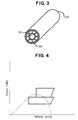
- Fig. 3 depicts an example of a heat exchanger having a double-pipe structure, capable of being applied to heat exchanger 9 in the first embodiment.
- the double-pipe structure 200 utilized as heat exchanger 9 is formed so that the gas-phase refrigerant separated by first gas/liquid separating chamber 101 passes through an inner passageway 201 and the gas-phase refrigerant flowed out from second gas/liquid separating chamber 105 passes through an outer passageway 202, and the gas-phase refrigerant, separated by first gas/liquid separating chamber 101 and being injected into compressor 2, is cooled by heat exchange between both gas-phase refrigerants.
- Fig. 4 depicts a Mollier chart, showing the operation of the refrigerating cycle in the first embodiment.
- the axis of the abscissa represents the enthalpy, and the axis of the ordinate represents the pressure.
- the number of junction parts can be decreased, the entire structure of the refrigerating cycle can be simplified and reduced in cost, and the fear of refrigerant leakage and the like can be removed.
- the gas-phase refrigerant injected into compressor 2 can be cooled by heat exchange between the refrigerant being injected into the compressor 2 and the refrigerant being sucked into the compressor 2, the advantage due to the injection can be increased, and the efficiency as the whole of the refrigerating cycle can be improved.
- Fig. 5 depicts a vapor compression refrigerating cycle using carbon dioxide, according to a second embodiment of the present invention.
- the basic structure of this refrigerating cycle according to the second embodiment is same as that of the refrigerating cycle according to the first embodiment.
- the position for incorporating second expansion device 6 in the gas/liquid separator is different from that in the first embodiment. The operation of the second embodiment will be explained referring to Fig. 6.
- Fig. 6 depicts a detailed structure of gas/liquid separator module 7 according to the second embodiment.
- Refrigerant storing vessel 100 provided as gas/liquid separator module 7 is separated therein into a first gas/liquid separating chamber 101 formed as a first gas/liquid separating means and a second gas/liquid separating chamber 105 formed as a second gas/liquid separating means, similarly to in the first embodiment.
- Both gas/liquid separating chambers have a function for separation into gas and liquid phases.
- the refrigerant from radiator 3 is flowed from a high-pressure refrigerant inlet port 112, reduced in pressure by a first expansion device 102, flowed into first gas/liquid separating chamber 101 from a middle-pressure refrigerant inlet port 103, and separated into middle-pressure gas-phase and liquid-phase refrigerants.
- the middle-pressure gas-phase refrigerant separated by first gas/liquid separating chamber 101 passes through middle-pressure refrigerant passageway 104 and flows out from middle-pressure refrigerant outlet port 114.
- first gas/liquid separating chamber 101 passes through refrigerant tube 107, and it is reduced in pressure by second expansion device 106, and flows out from low-pressure refrigerant outlet port 116 toward evaporator 8. At that time, a part of refrigerant tube 107 comes into contact with low-pressure liquid-phase refrigerant 118 as shown in the figure, and it is possible to cool the refrigerant flowing in the refrigerant tube 107.
- the refrigerant flowing in the refrigerant tube 107 can be cooled by the gas-phase refrigerant and the liquid-phase refrigerant in the second gas/liquid separating chamber 105, and the refrigeration ability can be increased.
- the gas and liquid two-phase refrigerant flowed out from evaporator 8 passes through refrigerant tube 108 from refrigerant inlet port 113, flows into second gas/liquid separating chamber 105, and therein, is separated into low-pressure gas-phase and liquid-phase refrigerants.
- the separated low-pressure liquid-phase refrigerant 118 is stored at a lower part in second gas/liquid separating chamber 105, oil 119 for being contained in the refrigerant flowed in for lubricating the refrigerating cycle is stored in the bottom part in second gas/liquid separating chamber 105, and the separated gas-phase refrigerant is discharged through refrigerant tube 109 toward the suction side of compressor 2. Oil 119 stored in the bottom part in second gas/liquid separating chamber 105 is sucked from oil returning hole 111 disposed at a lower part of refrigerant discharge tube 109, and the sucked oil is sent to compressor 2 through the refrigerant discharge tube 109 together with the low-pressure gas-phase refrigerant.
- diffuser 110 prevents the gas and liquid two-phase refrigerant, passing through low-pressure refrigerant inlet port 113 and being flowed in from refrigerant tube 108, from being flowed directly into refrigerant discharge tube 109.
- the oil and the liquid-phase refrigerant are not completely separated from each other as shown in the figure, and in practice, the liquid-phase refrigerant is contained in the oil more or less.
- means for accelerating the heat exchange such as fins may be provided to refrigerant tube 107.
- Fig. 7 depicts a Mollier chart, showing the operation of the refrigerating cycle in the second embodiment. As shown in Fig. 7, a supercooling region appears partially, as compared with the Mollier chart in the first embodiment depicted in Fig. 4.
- the efficiency of compressor 2 can be improved and the consumption power required for the compression can be decreased.
- the gas/liquid separator and the pressure-reducing mechanism with each other (forming the integrated gas/liquid separator module 7), it becomes possible to decrease the number of junction parts, simplify the structure, reduce in cost, and remove the fear of refrigerant leakage.
- the injected refrigerant can be cooled, and the advantage due to the injection can be increased.
- the vapor compression refrigerating cycle according to the present invention can be applied to any vapor compression refrigerating cycle capable of operating in a supercritical region of refrigerant, and in particular, it is suitable for a refrigerating cycle using carbon dioxide which is a natural-system refrigerant, and especially, suitable as a refrigerating cycle used for an air conditioning system for vehicles.
Landscapes
- Engineering & Computer Science (AREA)
- Physics & Mathematics (AREA)
- Mechanical Engineering (AREA)
- Thermal Sciences (AREA)
- General Engineering & Computer Science (AREA)
- Chemical & Material Sciences (AREA)
- Chemical Kinetics & Catalysis (AREA)
- Analytical Chemistry (AREA)
- Power Engineering (AREA)
- Air-Conditioning For Vehicles (AREA)
- Applications Or Details Of Rotary Compressors (AREA)
Abstract
Description
- The present invention relates to a vapor compression refrigerating cycle, and specifically, to a vapor compression refrigerating cycle using carbon dioxide, which is a natural-system refrigerant, suitable particularly as a refrigerating cycle used in an air conditioning system for vehicles.
- In a case where carbon dioxide, which is a natural-system refrigerant, is used as refrigerant of a vapor compression refrigerating cycle in an air conditioning system for vehicles, a structure is known wherein a pressure of a high-pressure side line of refrigerant is adjusted by controlling an opening degree of a valve of an expansion device by an external signal (for example,
JP-A-7-294033 - While an electric expansion means and the like is thus controlled by referring to the refrigerant temperature of the high-pressure side so that the pressure of the high-pressure side becomes an optimum pressure, in order to adjust an air temperature at an exit of an evaporator, a displacement of an external signal control type variable displacement compressor is controlled, and the signal for controlling the displacement of the compressor is calculated generally from the information of thermal load, etc.
- In such a refrigerating cycle, however, although the coefficient of performance as the refrigerating cycle is increased, the power for the compressor cannot be decreased so much. Concretely, in a case where an outside air temperature or a refrigerant temperature at an exit of a radiator is much higher than the critical temperature of the refrigerant, even though the above-described high-pressure side pressure is controlled to be optimum, it is considered that there is a case where the refrigeration ability of the system decreases, and the consumption power of the compressor greatly increases as compared with a usual load (a load in a case where an outside air temperature or a refrigerant temperature at an exit of a radiator is close to a critical temperature of refrigerant), thereby reducing the coefficient of performance of the system. In order to cope with such a problem, a gas injection cycle (a cycle for introducing gas-phase refrigerant, separated by a gas/liquid separator, into a midway of a compression step of a compressor) is disclosed in
JP-A-11-63694 JP-A-10-288411 - Generally, the refrigerating cycle of such a gas injection cycle is structured as a system provided with a gas/liquid separator between two expansion means. Further, in a refrigerating cycle using carbon dioxide, it is difficult to control a degree of superheating of refrigerant at an exit of an evaporator, and further, it is necessary to separate the refrigerant at the exit of the evaporator into gas/liquid phases by a gas/liquid separator and flow out only the gas-phase refrigerant to a suction side of a compressor in order to deal with a variation of a load to the system. Further, at a step for flowing out the gas-phase refrigerant separated by the gas/liquid separator, usually oil returning is required in order to return lubricant oil in the refrigerant to the compressor, but, because the refrigerant is not perfectly separated into two phases of gas/liquid phases in the gas/liquid separator, it is considered that the refrigerant flowed into the compressor is slightly mixed with a wet vapor. Also from such a viewpoint, it is necessary to control the refrigerant sucked into the compressor at a condition provided with a degree of superheating. Furthermore, there may be a fear of a leakage of refrigerant ascribed to increase of the number of junction parts between the two expansion means and the gas/liquid separator and the like.
- Accordingly, it would be desirable to provide a vapor compression refrigerating cycle with a structure of gas injection cycle, in particular, a vapor compression refrigerating cycle using carbon dioxide refrigerant which is a natural-system refrigerant, in which, by forming a structure of gas injection cycle while maintaining a good refrigeration ability, an efficiency of a compressor is improved and a consumption power required for the compressor is decreased, and while the efficiency as the whole of the refrigeration cycle is improved, the number of junction parts is decreased particularly by integrating a gas/liquid separator and expansion means, thereby simplifying the entire structure of the refrigerating cycle, reducing the cost thereof, and removing the fear of refrigerant leakage and the like. Further, it would be desirable to provide a vapor compression refrigerating cycle which can cool the refrigerant to be injected and achieve a further high efficiency by employing a new structure for exchanging heat between the refrigerant injected into a compressor and the refrigerant sucked into the compressor.
- A vapor compression refrigerating cycle according to the present invention can operate in a supercritical region of refrigerant, the refrigerating cycle has a compressor for compressing refrigerant and discharging compressed refrigerant, a radiator for cooling high-temperature and high-pressure refrigerant compressed by the compressor, a first pressure-reducing means for reducing the pressure of refrigerant cooled by the radiator, a first gas/liquid separating means for separating refrigerant reduced in pressure by the first pressure-reducing means into gas-phase refrigerant and liquid-phase refrigerant, a second pressure-reducing means for reducing the pressure of liquid-phase refrigerant separated by the first gas/liquid separating means, an evaporator for evaporating refrigerant reduced in pressure by the second pressure-reducing means, and a second gas/liquid separating means for separating refrigerant evaporated by the evaporator into gas-phase refrigerant and liquid-phase refrigerant, wherein the gas-phase refrigerant separated by the second gas/liquid separating means is flowed out to a suction side of the compressor and compressed by the compressor, and the gas-phase refrigerant separated by the first gas/liquid separating means is introduced into a midway of a compression step of the compressor, and the vapor compression refrigerating cycle is characterized in that the first pressure-reducing means and the first gas/liquid separating means are integrated with each other, or/and, the second pressure-reducing means and the second gas/liquid separating means are integrated with each other (a first structure). Namely, by integrating the pressure-reducing means and the gas/liquid separating means with each other, the number of junction parts is decreased, the entire structure of the refrigerating cycle is simplified and reduced in cost, and the fear of refrigerant leakage and the like is removed. Further, basically by forming the refrigerating cycle as a gas injection cycle, the efficiency of the compressor is improved and the consumption power required for the compression is decreased, and therefore, the efficiency as the whole of the refrigerating cycle is improved.
- Further, a vapor compression refrigerating cycle according to the present invention can operate in a supercritical region of refrigerant, the refrigerating cycle has a compressor for compressing refrigerant and discharging compressed refrigerant, a radiator for cooling high-temperature and high-pressure refrigerant compressed by the compressor, a first pressure-reducing means for reducing the pressure of refrigerant cooled by the radiator, a first gas/liquid separating means for separating refrigerant reduced in pressure by the first pressure-reducing means into gas-phase refrigerant and liquid-phase refrigerant, a second pressure-reducing means for reducing the pressure of liquid-phase refrigerant separated by the first gas/liquid separating means, an evaporator for evaporating refrigerant reduced in pressure by the second pressure-reducing means, and a second gas/liquid separating means for separating refrigerant evaporated by the evaporator into gas-phase refrigerant and liquid-phase refrigerant, wherein the gas-phase refrigerant separated by the second gas/liquid separating means is flowed out to a suction side of the compressor and compressed by the compressor, and the gas-phase refrigerant separated by the first gas/liquid separating means is introduced into a midway of a compression step of the compressor, and the refrigerating cycle is characterized in that a heat exchanging means for exchanging heat between the gas-phase refrigerant flowed out from the first gas/liquid separating means and sent to the compressor and the gas-phase refrigerant flowed out from the second gas/liquid separating means and sent to the compressor is provided (a second structure). Namely, by exchanging heat between the refrigerant injected into the compressor and the refrigerant sucked into the compressor, the injected refrigerant is cooled, the advantage due to the injection is increased, and therefore, the efficiency as the whole of the refrigerating cycle is improved.
- Moreover, in the present invention, a structure combined with the above-described first and second structures may be employed. Namely, a vapor compression refrigerating cycle according to the present invention can operate in a supercritical region of refrigerant, the refrigerating cycle has a compressor for compressing refrigerant and discharging compressed refrigerant, a radiator for cooling high-temperature and high-pressure refrigerant compressed by the compressor, a first pressure-reducing means for reducing the pressure of refrigerant cooled by the radiator, a first gas/liquid separating means for separating refrigerant reduced in pressure by the first pressure-reducing means into gas-phase refrigerant and liquid-phase refrigerant, a second pressure-reducing means for reducing the pressure of liquid-phase refrigerant separated by the first gas/liquid separating means, an evaporator for evaporating refrigerant reduced in pressure by the second pressure-reducing means, and a second gas/liquid separating means for separating refrigerant evaporated by the evaporator into gas-phase refrigerant and liquid-phase refrigerant, wherein the gas-phase refrigerant separated by the second gas/liquid separating means is flowed out to a suction side of the compressor and compressed by the compressor, and the gas-phase refrigerant separated by the first gas/liquid separating means is introduced into a midway of a compression step of the compressor, and the refrigerating cycle is characterized in that the first pressure-reducing means and the first gas/liquid separating means are integrated with each other, or/and, the second pressure-reducing means and the second gas/liquid separating means are integrated with each other, and a heat exchanging means for exchanging heat between the gas-phase refrigerant flowed out from the first gas/liquid separating means and sent to the compressor and the gas-phase refrigerant flowed out from the second gas/liquid separating means and sent to the compressor is provided (a third structure).
- In such refrigerating cycles according to the present invention, a structure may be employed wherein the first gas/liquid separating means and the second gas/liquid separating means are integrated with each other. In such a structure, further the number of junction parts can be decreased, the entire structure of the refrigerating cycle can be simplified and reduced in cost, and the fear of refrigerant leakage and the like can be removed.
- Further, a structure may be employed wherein the first gas/liquid separating means, the second gas/liquid separating means, the first pressure-reducing means and the second pressure-reducing means are all integrated with each other. In such a structure, the number of junction parts can be further decreased, the entire structure of the refrigerating cycle can be further simplified and further reduced in cost, and the fear of refrigerant leakage and the like can be removed more surely.
- In the structure thus integrated, for example, as shown in Fig. 2 described later, a structure may be employed wherein the first gas/liquid separating means and the second gas/liquid separating means are formed as an integral vessel, the first pressure-reducing means is incorporated into a refrigerant passageway extending from a first inlet port of the first gas/liquid separating means opening at a side of the radiator to a second inlet port of the first gas/liquid separating means opening toward an interior of the first gas/liquid separating means, and the second pressure-reducing means is provided in a refrigerant passage route extending from an outlet port of the first gas/liquid separating means for discharging liquid-phase refrigerant from the first gas/liquid separating means to a position of the evaporator. In such a structure, the integrated portion can be made compact efficiently.
- In this structure, a structure may be employed wherein a refrigerant passageway forming a part of the refrigerant passage route passes through a refrigerant storing space formed in the second gas/liquid separating means. Moreover, a structure may be employed wherein the refrigerant passageway forming a part of the refrigerant passage route is formed so as to pass through the refrigerant storing space formed in the second gas/liquid separating means and come into contact with liquid-phase refrigerant separated by the second gas/liquid separating means and stored in the refrigerant storing space.
- Further, in the above-described integrated structure, for example, as shown in Fig. 6 described later, a structure may be employed wherein the first gas/liquid separating means and the second gas/liquid separating means are formed as an integral vessel, the first pressure-reducing means is incorporated into a refrigerant passageway extending from a first inlet port of the first gas/liquid separating means opening at a side of the radiator to a second inlet port of the first gas/liquid separating means opening toward an interior of the first gas/liquid separating means, and a refrigerant passage route extending from the first gas/liquid separating means to the second pressure-reducing means passes through a refrigerant storing space formed in the second gas/liquid separating means. Moreover, a structure may be employed wherein this refrigerant passage route extending from the first gas/liquid separating means to the second pressure-reducing means is formed so as to pass through the refrigerant storing space formed in the second gas/liquid separating means and come into contact with liquid-phase refrigerant separated by the second gas/liquid separating means and stored in the refrigerant storing space.
- Such vapor compression refrigerating cycles according to the present invention are suitable as refrigerating cycles including supercritical region of refrigerant, in particular, for a case where carbon dioxide is used as the refrigerant for the vapor compression refrigerating cycle. Further, the vapor compression refrigerating cycles according to the present invention are suitable as refrigerating cycles used for an air conditioning system for a vehicle.
- Thus, in the vapor compression refrigerating cycle according to the present invention, while the efficiency of the compressor can be improved and the consumption power required for the compressor can be decreased by employing a structure of a gas injection cycle, by integrating the pressure-reducing means and the gas/liquid separating means with each other, the number of junction parts can be decreased, the entire structure of the refrigerating cycle can be simplified and reduced in cost, and the fear of refrigerant leakage and the like can be removed. Further, by exchanging heat between the refrigerant injected into the compressor and the refrigerant sucked into the compressor, the injected refrigerant can be cooled, the advantage due to the injection can be increased, and the efficiency as the whole of the refrigerating cycle can be improved. These advantages can be both achieved by combining the first structure and the second structure described above.
- Further objects, features, and advantages of the present invention will be understood from the following detailed description of preferred embodiments of the present invention with reference to the accompanying figures.
- Embodiments of the invention now are described with reference to the accompanying figures, which are given by way of example only, and are not intended to limit the present invention.
- Fig. 1 is a schematic diagram of a vapor compression refrigerating cycle according to a first embodiment of the present invention.
- Fig. 2 is a vertical sectional view of a gas/liquid separator module in the first embodiment.
- Fig. 3 is a perspective view of a double-pipe type heat exchanger, showing an example of a heat exchanging means in the first embodiment.
- Fig. 4 is a Mollier chart of the first embodiment.
- Fig. 5 is a schematic diagram of a vapor compression refrigerating cycle according to a second embodiment of the present invention.
- Fig. 6 is a vertical sectional view of a gas/liquid separator module in the second embodiment.
- Fig. 7 is a Mollier chart of the second embodiment.
- Hereinafter, desirable embodiments of the present invention will be explained referring to the drawings.
- Fig. 1 depicts a vapor compression refrigerating cycle according to a first embodiment of the present invention for use in an air conditioning system for a vehicle, using carbon dioxide which is a natural-system refrigerant. Refrigerating
cycle 1 is provided relative to anair path 11 provided with ablower 10. First, the operation of this refrigeratingcycle 1 will be explained. Refrigerant compressed by acompressor 2 is introduced into aradiator 3, and at theradiator 3, the refrigerant is exchanged in heat with an outside fluid (for example, air) using a fan forradiator 4 and the like. The refrigerant cooled by and discharged fromradiator 3 is reduced in pressure by an orifice provided as afirst expansion device 5 forming a first pressure-reducing means. The pressure-reduced refrigerant is separated into gas-phase refrigerant and liquid-phase refrigerant by a first gas/liquid separating chamber (a first gas/liquid separating means) in a gas/liquid separator module 7 formed by integrating a first gas/liquid separating means and a second gas/liquid separating means with each other. The separated liquid-phase refrigerant is reduced in pressure by an orifice provided as asecond expansion device 6 forming a second pressure-reducing means, and the pressure-reduced refrigerant is introduced into anevaporator 8 and exchanged in heat with an outside fluid (for example, air in air path 11). The refrigerant flowed out fromevaporator 8 is separated into gas-phase refrigerant and liquid-phase refrigerant by a second gas/liquid separating chamber (a second gas/liquid separating means) in gas/liquid separator module 7. The separated liquid-phase refrigerant is stored in gas/liquid separator module 7, and the gas-phase refrigerant is discharged from gas/liquid separator module 7, and flowed intocompressor 8 and compressed by thecompressor 8. Further, the gas-phase refrigerant flowed out from the first gas/liquid separating chamber provided in gas/liquid separator module 7 is cooled atheat exchanger 9 by the gas-phase refrigerant flowed out from the second gas/liquid separating chamber provided in gas/liquid separator module 7, and injected into compressor 2 (into a midway of the compression step of compressor 2). Thiscompressor 2 of this refrigeratingcycle 1 is a fixed displacement compressor or a variable displacement compressor, and its drive source may be either an engine of a vehicle or a drive source except an engine. - Fig. 2 depicts a detailed structure of gas/
liquid separator module 7 according to the first embodiment.Refrigerant storing vessel 100 provided as gas/liquid separator module 7 is separated therein into a first gas/liquid separating chamber 101 formed as a first gas/liquid separating means and a second gas/liquid separating chamber 105 formed as a second gas/liquid separating means. Both gas/liquid separating chambers have a function for separation into gas and liquid phases. The refrigerant fromradiator 3 is flowed from a high-pressurerefrigerant inlet port 112, reduced in pressure by afirst expansion device 102, flowed into first gas/liquid separating chamber 101 from a middle-pressurerefrigerant inlet port 103, and separated into middle-pressure gas-phase and liquid-phase refrigerants. The middle-pressure gas-phase refrigerant separated by first gas/liquid separating chamber 101 passes through a middle-pressure refrigerant passageway 104 and flows out from a middle-pressurerefrigerant outlet port 114. Further, the middle-pressure liquid-phase refrigerant separated by first gas/liquid separating chamber 101 is reduced in pressure by asecond expansion device 106, passes through a refrigerant storing space in second gas/liquid separating chamber 105 and passes through arefrigerant tube 107 provided so as to come into contact with stored liquid-phase refrigerant 118, and thereafter, flows out from a low-pressurerefrigerant outlet port 116 towardevaporator 8. Where, althoughsecond expansion device 106 provided as a second pressure-reducing means may be provided in a refrigerant passage route extending from a position ofrefrigerant outlet port 120 from first gas/liquid separating chamber 101 to a position ofevaporator 8, in this embodiment it is provided immediately after therefrigerant outlet port 120. The gas and liquid two-phase refrigerant flowed out fromevaporator 8 passes through arefrigerant tube 108 extending from a low-pressurerefrigerant inlet port 113 through first gas/liquid separating chamber 101, flows into second gas/liquid separating chamber 105, and therein, is separated into low-pressure gas-phase and liquid-phase refrigerants. The separated low-pressure liquid-phase refrigerant 118 is stored at a lower part in second gas/liquid separating chamber 105,oil 119 for being contained in the refrigerant flowed in for lubricating the refrigerating cycle is stored in the bottom part in second gas/liquid separating chamber 105, and the separated low-pressure gas-phase refrigerant is discharged through arefrigerant tube 109 toward the suction side ofcompressor 2.Oil 119 stored in the bottom part in second gas/liquid separating chamber 105 is sucked from anoil returning hole 111 disposed at a lower part of arefrigerant discharge tube 109, and the sucked oil is sent tocompressor 2 through therefrigerant discharge tube 109 and a low-pressurerefrigerant outlet port 115 together with low-pressure gas-phase refrigerant. Further, adiffuser 110 prevents the gas and liquid two-phase refrigerant, passing through low-pressurerefrigerant inlet port 113 and being flowed in fromrefrigerant tube 108, from being flowed directly intorefrigerant discharge tube 109. Where, it is considered that the oil and the liquid-phase refrigerant are not completely separated from each other as shown in the figure, and in practice, the liquid-phase refrigerant is contained in the oil more or less. - Fig. 3 depicts an example of a heat exchanger having a double-pipe structure, capable of being applied to
heat exchanger 9 in the first embodiment. The double-pipe structure 200 utilized asheat exchanger 9 is formed so that the gas-phase refrigerant separated by first gas/liquid separating chamber 101 passes through aninner passageway 201 and the gas-phase refrigerant flowed out from second gas/liquid separating chamber 105 passes through anouter passageway 202, and the gas-phase refrigerant, separated by first gas/liquid separating chamber 101 and being injected intocompressor 2, is cooled by heat exchange between both gas-phase refrigerants. - Fig. 4 depicts a Mollier chart, showing the operation of the refrigerating cycle in the first embodiment. The axis of the abscissa represents the enthalpy, and the axis of the ordinate represents the pressure.
- In the above-described first embodiment, by employing the structure of gas/
liquid separator module 7 in which the first gas/liquid separating means, the second gas/liquid separating means, the first pressure-reducing means and the second pressure-reducing means are all integrated with each other, the number of junction parts can be decreased, the entire structure of the refrigerating cycle can be simplified and reduced in cost, and the fear of refrigerant leakage and the like can be removed. Further, because the gas-phase refrigerant injected intocompressor 2 can be cooled by heat exchange between the refrigerant being injected into thecompressor 2 and the refrigerant being sucked into thecompressor 2, the advantage due to the injection can be increased, and the efficiency as the whole of the refrigerating cycle can be improved. - Fig. 5 depicts a vapor compression refrigerating cycle using carbon dioxide, according to a second embodiment of the present invention. The basic structure of this refrigerating cycle according to the second embodiment is same as that of the refrigerating cycle according to the first embodiment. In this refrigerating cycle according to the second embodiment, however, the position for incorporating
second expansion device 6 in the gas/liquid separator is different from that in the first embodiment. The operation of the second embodiment will be explained referring to Fig. 6. - Fig. 6 depicts a detailed structure of gas/
liquid separator module 7 according to the second embodiment.Refrigerant storing vessel 100 provided as gas/liquid separator module 7 is separated therein into a first gas/liquid separating chamber 101 formed as a first gas/liquid separating means and a second gas/liquid separating chamber 105 formed as a second gas/liquid separating means, similarly to in the first embodiment. Both gas/liquid separating chambers have a function for separation into gas and liquid phases. The refrigerant fromradiator 3 is flowed from a high-pressurerefrigerant inlet port 112, reduced in pressure by afirst expansion device 102, flowed into first gas/liquid separating chamber 101 from a middle-pressurerefrigerant inlet port 103, and separated into middle-pressure gas-phase and liquid-phase refrigerants. The middle-pressure gas-phase refrigerant separated by first gas/liquid separating chamber 101 passes through middle-pressure refrigerant passageway 104 and flows out from middle-pressurerefrigerant outlet port 114. Further, the middle-pressure liquid-phase refrigerant separated by first gas/liquid separating chamber 101 passes throughrefrigerant tube 107, and it is reduced in pressure bysecond expansion device 106, and flows out from low-pressurerefrigerant outlet port 116 towardevaporator 8. At that time, a part ofrefrigerant tube 107 comes into contact with low-pressure liquid-phase refrigerant 118 as shown in the figure, and it is possible to cool the refrigerant flowing in therefrigerant tube 107. Further, because it is also possible to exchange heat between therefrigerant tube 107 and the gas-phase refrigerant in second gas/liquid separating chamber 105, the refrigerant flowing in therefrigerant tube 107 can be cooled by the gas-phase refrigerant and the liquid-phase refrigerant in the second gas/liquid separating chamber 105, and the refrigeration ability can be increased. The gas and liquid two-phase refrigerant flowed out fromevaporator 8 passes throughrefrigerant tube 108 fromrefrigerant inlet port 113, flows into second gas/liquid separating chamber 105, and therein, is separated into low-pressure gas-phase and liquid-phase refrigerants. The separated low-pressure liquid-phase refrigerant 118 is stored at a lower part in second gas/liquid separating chamber 105,oil 119 for being contained in the refrigerant flowed in for lubricating the refrigerating cycle is stored in the bottom part in second gas/liquid separating chamber 105, and the separated gas-phase refrigerant is discharged throughrefrigerant tube 109 toward the suction side ofcompressor 2.Oil 119 stored in the bottom part in second gas/liquid separating chamber 105 is sucked fromoil returning hole 111 disposed at a lower part ofrefrigerant discharge tube 109, and the sucked oil is sent tocompressor 2 through therefrigerant discharge tube 109 together with the low-pressure gas-phase refrigerant. Further,diffuser 110 prevents the gas and liquid two-phase refrigerant, passing through low-pressurerefrigerant inlet port 113 and being flowed in fromrefrigerant tube 108, from being flowed directly intorefrigerant discharge tube 109. Where, it is considered that the oil and the liquid-phase refrigerant are not completely separated from each other as shown in the figure, and in practice, the liquid-phase refrigerant is contained in the oil more or less. Further, in this second embodiment, means for accelerating the heat exchange such as fins may be provided torefrigerant tube 107. - Fig. 7 depicts a Mollier chart, showing the operation of the refrigerating cycle in the second embodiment. As shown in Fig. 7, a supercooling region appears partially, as compared with the Mollier chart in the first embodiment depicted in Fig. 4.
- Thus, in the above-described respective embodiments, in the vapor compression refrigerating cycle using carbon dioxide, which is a natural-system refrigerant, as the refrigerant of the refrigerating cycle, by employing the form of a gas injection cycle, the efficiency of
compressor 2 can be improved and the consumption power required for the compression can be decreased. Further, by integrating the gas/liquid separator and the pressure-reducing mechanism with each other (forming the integrated gas/liquid separator module 7), it becomes possible to decrease the number of junction parts, simplify the structure, reduce in cost, and remove the fear of refrigerant leakage. Furthermore, by exchanging heat between the refrigerant injected intocompressor 2 and the refrigerant sucked into thecompressor 2, the injected refrigerant can be cooled, and the advantage due to the injection can be increased. - The vapor compression refrigerating cycle according to the present invention can be applied to any vapor compression refrigerating cycle capable of operating in a supercritical region of refrigerant, and in particular, it is suitable for a refrigerating cycle using carbon dioxide which is a natural-system refrigerant, and especially, suitable as a refrigerating cycle used for an air conditioning system for vehicles.
Claims (12)
- A vapor compression refrigerating cycle capable of operating in a supercritical region of refrigerant, said refrigerating cycle having a compressor for compressing refrigerant and discharging compressed refrigerant, a radiator for cooling high-temperature and high-pressure refrigerant compressed by said compressor, a first pressure-reducing means for reducing the pressure of refrigerant cooled by said radiator, a first gas/liquid separating means for separating refrigerant reduced in pressure by said first pressure-reducing means into gas-phase refrigerant and liquid-phase refrigerant, a second pressure-reducing means for reducing the pressure of liquid-phase refrigerant separated by said first gas/liquid separating means, an evaporator for evaporating refrigerant reduced in pressure by said second pressure-reducing means, and a second gas/liquid separating means for separating refrigerant evaporated by said evaporator into gas-phase refrigerant and liquid-phase refrigerant, wherein the gas-phase refrigerant separated by said second gas/liquid separating means is flowed out to a suction side of said compressor and compressed by said compressor, and the gas-phase refrigerant separated by said first gas/liquid separating means is introduced into a midway of a compression step of said compressor, characterized in that said first pressure-reducing means and said first gas/liquid separating means are integrated with each other, or/and, said second pressure-reducing means and said second gas/liquid separating means are integrated with each other.
- A vapor compression refrigerating cycle capable of operating in a supercritical region of refrigerant, said refrigerating cycle having a compressor for compressing refrigerant and discharging compressed refrigerant, a radiator for cooling high-temperature and high-pressure refrigerant compressed by said compressor, a first pressure-reducing means for reducing the pressure of refrigerant cooled by said radiator, a first gas/liquid separating means for separating refrigerant reduced in pressure by said first pressure-reducing means into gas-phase refrigerant and liquid-phase refrigerant, a second pressure-reducing means for reducing the pressure of liquid-phase refrigerant separated by said first gas/liquid separating means, an evaporator for evaporating refrigerant reduced in pressure by said second pressure-reducing means, and a second gas/liquid separating means for separating refrigerant evaporated by said evaporator into gas-phase refrigerant and liquid-phase refrigerant, wherein the gas-phase refrigerant separated by said second gas/liquid separating means is flowed out to a suction side of said compressor and compressed by said compressor, and the gas-phase refrigerant separated by said first gas/liquid separating means is introduced into a midway of a compression step of said compressor, characterized in that a heat exchanging means for exchanging heat between the gas-phase refrigerant flowed out from said first gas/liquid separating means and sent to said compressor and the gas-phase refrigerant flowed out from said second gas/liquid separating means and sent to said compressor is provided.
- A vapor compression refrigerating cycle capable of operating in a supercritical region of refrigerant, said refrigerating cycle having a compressor for compressing refrigerant and discharging compressed refrigerant, a radiator for cooling high-temperature and high-pressure refrigerant compressed by said compressor, a first pressure-reducing means for reducing the pressure of refrigerant cooled by said radiator, a first gas/liquid separating means for separating refrigerant reduced in pressure by said first pressure-reducing means into gas-phase refrigerant and liquid-phase refrigerant, a second pressure-reducing means for reducing the pressure of liquid-phase refrigerant separated by said first gas/liquid separating means, an evaporator for evaporating refrigerant reduced in pressure by said second pressure-reducing means, and a second gas/liquid separating means for separating refrigerant evaporated by said evaporator into gas-phase refrigerant and liquid-phase refrigerant, wherein the gas-phase refrigerant separated by said second gas/liquid separating means is flowed out to a suction side of said compressor and compressed by said compressor, and the gas-phase refrigerant separated by said first gas/liquid separating means is introduced into a midway of a compression step of said compressor, characterized in that said first pressure-reducing means and said first gas/liquid separating means are integrated with each other, or/and, said second pressure-reducing means and said second gas/liquid separating means are integrated with each other, and a heat exchanging means for exchanging heat between the gas-phase refrigerant flowed out from said first gas/liquid separating means and sent to said compressor and the gas-phase refrigerant flowed out from said second gas/liquid separating means and sent to said compressor is provided.
- The vapor compression refrigerating cycle according to any preceding claim, wherein said first gas/liquid separating means and said second gas/liquid separating means are integrated with each other.
- The vapor compression refrigerating cycle according to any preceding claim, wherein said first gas/liquid separating means, said second gas/liquid separating means, said first pressure-reducing means and said second pressure-reducing means are all integrated with each other.
- The vapor compression refrigerating cycle according to claim 5, wherein said first gas/liquid separating means and said second gas/liquid separating means are formed as an integral vessel, said first pressure-reducing means is incorporated into a refrigerant passageway extending from a first inlet port of said first gas/liquid separating means opening at a side of said radiator to a second inlet port of said first gas/liquid separating means opening toward an interior of said first gas/liquid separating means, and said second pressure-reducing means is provided in a refrigerant passage route extending from an outlet port of said first gas/liquid separating means for discharging liquid-phase refrigerant from said first gas/liquid separating means to a position of said evaporator.
- The vapor compression refrigerating cycle according to claim 6, wherein a refrigerant passageway forming a part of said refrigerant passage route passes through a refrigerant storing space formed in said second gas/liquid separating means.
- The vapor compression refrigerating cycle according to claim 7, wherein said refrigerant passageway forming a part of said refrigerant passage route is formed so as to pass through said refrigerant storing space formed in said second gas/liquid separating means and come into contact with liquid-phase refrigerant separated by said second gas/liquid separating means and stored in said refrigerant storing space.
- The vapor compression refrigerating cycle according to claim 5, wherein said first gas/liquid separating means and said second gas/liquid separating means are formed as an integral vessel, said first pressure-reducing means is incorporated into a refrigerant passageway extending from a first inlet port of said first gas/liquid separating means opening at a side of said radiator to a second inlet port of said first gas/liquid separating means opening toward an interior of said first gas/liquid separating means, and a refrigerant passage route extending from said first gas/liquid separating means to said second pressure-reducing means passes through a refrigerant storing space formed in said second gas/liquid separating means.
- The vapor compression refrigerating cycle according to claim 9, wherein said refrigerant passage route extending from said first gas/liquid separating means to said second pressure-reducing means is formed so as to pass through said refrigerant storing space formed in said second gas/liquid separating means and come into contact with liquid-phase refrigerant separated by said second gas/liquid separating means and stored in said refrigerant storing space.
- The vapor compression refrigerating cycle according to any preceding claim, wherein carbon dioxide is used as refrigerant for said vapor compression refrigerating cycle.
- The vapor compression refrigerating cycle according to any preceding claim, wherein said vapor compression refrigerating cycle is used for an air conditioning system for a vehicle.
Applications Claiming Priority (1)
| Application Number | Priority Date | Filing Date | Title |
|---|---|---|---|
| JP2006146324A JP4776438B2 (en) | 2006-05-26 | 2006-05-26 | Refrigeration cycle |
Publications (2)
| Publication Number | Publication Date |
|---|---|
| EP1860390A2 true EP1860390A2 (en) | 2007-11-28 |
| EP1860390A3 EP1860390A3 (en) | 2008-07-23 |
Family
ID=38515416
Family Applications (1)
| Application Number | Title | Priority Date | Filing Date |
|---|---|---|---|
| EP07108417A Withdrawn EP1860390A3 (en) | 2006-05-26 | 2007-05-17 | Vapor compression refrigerating cycle |
Country Status (2)
| Country | Link |
|---|---|
| EP (1) | EP1860390A3 (en) |
| JP (1) | JP4776438B2 (en) |
Cited By (7)
| Publication number | Priority date | Publication date | Assignee | Title |
|---|---|---|---|---|
| US8327651B2 (en) | 2009-07-07 | 2012-12-11 | Hamilton Sundstrand Corporation | Transcritical fluid cooling for aerospace applications |
| WO2015184933A1 (en) * | 2014-06-05 | 2015-12-10 | 珠海格力电器股份有限公司 | Flash evaporator and air conditioning system having same |
| WO2016026253A1 (en) * | 2014-08-22 | 2016-02-25 | 珠海格力电器股份有限公司 | Flash tank and air conditioner having same |
| CN109073298A (en) * | 2016-12-27 | 2018-12-21 | 株式会社不二工机 | refrigerant container |
| US10234181B2 (en) | 2013-11-18 | 2019-03-19 | Carrier Corporation | Flash gas bypass evaporator |
| CN117553364A (en) * | 2024-01-09 | 2024-02-13 | 深圳中集天达吉荣航空制冷有限公司 | Aircraft ground air conditioning system based on phase change cold accumulation and control method |
| FR3156380A1 (en) * | 2023-12-06 | 2025-06-13 | Valeo Systemes Thermiques | Separation device for a refrigerant circuit |
Families Citing this family (6)
| Publication number | Priority date | Publication date | Assignee | Title |
|---|---|---|---|---|
| JP2012093051A (en) * | 2010-10-28 | 2012-05-17 | Fuji Koki Corp | Gas-liquid separator for heat pump and injection type heat pump system |
| JP5911728B2 (en) * | 2012-01-17 | 2016-04-27 | カルソニックカンセイ株式会社 | Gas-liquid separator and vehicle air conditioner |
| JP5920272B2 (en) * | 2013-03-29 | 2016-05-18 | 株式会社デンソー | Integrated valve |
| CN111801536B (en) * | 2018-03-27 | 2023-04-28 | 比泽尔制冷设备有限公司 | refrigeration equipment |
| WO2020208736A1 (en) * | 2019-04-10 | 2020-10-15 | 三菱電機株式会社 | Refrigeration cycle device |
| JP7439658B2 (en) * | 2020-06-30 | 2024-02-28 | 株式会社デンソー | Refrigeration cycle equipment |
Family Cites Families (20)
| Publication number | Priority date | Publication date | Assignee | Title |
|---|---|---|---|---|
| CH127367A (en) * | 1927-07-02 | 1928-08-16 | Escher Wyss Maschf Ag | Refrigeration system with multi-stage compression and multi-stage evaporation of the refrigerant. |
| US1860447A (en) * | 1928-07-21 | 1932-05-31 | York Ice Machinery Corp | Refrigeration |
| US1840955A (en) * | 1929-01-14 | 1932-01-12 | Baker Ice Machine Co Inc | Refrigeration system |
| DE884503C (en) * | 1943-11-12 | 1953-07-27 | Linde S Eismaschinen Akt Ges G | Method for operating compression refrigeration machines |
| US2500688A (en) * | 1948-08-24 | 1950-03-14 | Edward P Kellie | Refrigerating apparatus |
| DE800974C (en) * | 1949-08-19 | 1950-12-18 | Linde Eismasch Ag | Control device for the refrigerant in refrigeration systems |
| US3022638A (en) * | 1959-05-06 | 1962-02-27 | Carrier Corp | Controls for refrigeration apparatus |
| JPS5397654A (en) * | 1977-02-07 | 1978-08-26 | Toshiba Corp | Air conditioner |
| JPS55158458A (en) * | 1979-05-24 | 1980-12-09 | Hitachi Ltd | Gassliquid separator for refrigeration cycle |
| JPS56105258A (en) * | 1980-01-28 | 1981-08-21 | Hitachi Ltd | Refrigerating cycle |
| US4341086A (en) * | 1980-10-06 | 1982-07-27 | Clarion Co., Ltd. | Refrigeration system |
| JPS6243280A (en) * | 1985-08-20 | 1987-02-25 | Sanyo Electric Co Ltd | Recording and reproducing device for video signal |
| JPH10132394A (en) * | 1996-10-31 | 1998-05-22 | Daikin Ind Ltd | Refrigeration equipment |
| JP2000035251A (en) * | 1998-07-17 | 2000-02-02 | Zexel Corp | Three layers separator in cooling cycle |
| JP2000046420A (en) * | 1998-07-31 | 2000-02-18 | Zexel Corp | Refrigeration cycle |
| JP2001221517A (en) * | 2000-02-10 | 2001-08-17 | Sharp Corp | Supercritical refrigeration cycle |
| JP2004028460A (en) * | 2002-06-26 | 2004-01-29 | Denso Corp | Vapor compression refrigerator |
| FR2855254B1 (en) * | 2003-05-23 | 2007-04-06 | Valeo Climatisation | AIR CONDITIONING DEVICE, ESPECIALLY FOR A MOTOR VEHICLE, COMPRISING A LOOP WITH LIQUID / GAS SEPARATION |
| JP2005076914A (en) * | 2003-08-28 | 2005-03-24 | Tgk Co Ltd | Refrigeration cycle |
| JP2005214444A (en) * | 2004-01-27 | 2005-08-11 | Sanyo Electric Co Ltd | Refrigerator |
-
2006
- 2006-05-26 JP JP2006146324A patent/JP4776438B2/en not_active Expired - Fee Related
-
2007
- 2007-05-17 EP EP07108417A patent/EP1860390A3/en not_active Withdrawn
Cited By (12)
| Publication number | Priority date | Publication date | Assignee | Title |
|---|---|---|---|---|
| US8327651B2 (en) | 2009-07-07 | 2012-12-11 | Hamilton Sundstrand Corporation | Transcritical fluid cooling for aerospace applications |
| US10234181B2 (en) | 2013-11-18 | 2019-03-19 | Carrier Corporation | Flash gas bypass evaporator |
| WO2015184933A1 (en) * | 2014-06-05 | 2015-12-10 | 珠海格力电器股份有限公司 | Flash evaporator and air conditioning system having same |
| WO2016026253A1 (en) * | 2014-08-22 | 2016-02-25 | 珠海格力电器股份有限公司 | Flash tank and air conditioner having same |
| US10234182B2 (en) | 2014-08-22 | 2019-03-19 | Gree Electric Appliances, Inc. Of Zhuhai | Flash tank and air conditioner having the same |
| CN109073298A (en) * | 2016-12-27 | 2018-12-21 | 株式会社不二工机 | refrigerant container |
| EP3495754A4 (en) * | 2016-12-27 | 2020-04-08 | Fujikoki Corporation | Refrigerant container |
| US10821811B2 (en) | 2016-12-27 | 2020-11-03 | Fujikoki Corporation | Refrigerant container |
| CN109073298B (en) * | 2016-12-27 | 2021-06-22 | 株式会社不二工机 | Refrigerant container |
| FR3156380A1 (en) * | 2023-12-06 | 2025-06-13 | Valeo Systemes Thermiques | Separation device for a refrigerant circuit |
| CN117553364A (en) * | 2024-01-09 | 2024-02-13 | 深圳中集天达吉荣航空制冷有限公司 | Aircraft ground air conditioning system based on phase change cold accumulation and control method |
| CN117553364B (en) * | 2024-01-09 | 2024-04-02 | 深圳中集天达吉荣航空制冷有限公司 | Aircraft ground air conditioning system based on phase change cold accumulation and control method |
Also Published As
| Publication number | Publication date |
|---|---|
| JP2007315687A (en) | 2007-12-06 |
| EP1860390A3 (en) | 2008-07-23 |
| JP4776438B2 (en) | 2011-09-21 |
Similar Documents
| Publication | Publication Date | Title |
|---|---|---|
| JP4626531B2 (en) | Ejector refrigeration cycle | |
| EP1347251B1 (en) | Method for increasing efficiency of a vapor compression system by evaporator heating | |
| JP3813702B2 (en) | Vapor compression refrigeration cycle | |
| US7654108B2 (en) | Unit for refrigerant cycle device | |
| US7823401B2 (en) | Refrigerant cycle device | |
| EP1813887B1 (en) | Air conditioning device | |
| KR100360006B1 (en) | Transcritical vapor compression cycle | |
| JP3365273B2 (en) | Refrigeration cycle | |
| US7770412B2 (en) | Integrated unit for refrigerant cycle device and manufacturing method of the same | |
| EP1884725A2 (en) | Two-stage expansion refrigerating device | |
| US11370271B2 (en) | Device for an air conditioning system of a motor vehicle and method for operating the device | |
| JP5050563B2 (en) | Ejector and ejector type refrigeration cycle unit | |
| US7694529B2 (en) | Refrigerant cycle device with ejector | |
| US7059150B2 (en) | Vapor-compression refrigerant cycle system with ejector | |
| EP2339266B1 (en) | Refrigerating apparatus | |
| EP1862749A2 (en) | Vapor Compression Refrigeration Cycle | |
| JP4952830B2 (en) | Ejector refrigeration cycle | |
| JP2010133606A (en) | Ejector type refrigerating cycle | |
| US11656014B2 (en) | Heat exchanger | |
| JP5359231B2 (en) | Ejector refrigeration cycle | |
| JP4776438B2 (en) | Refrigeration cycle | |
| US7370493B2 (en) | Vapor compression refrigerating systems | |
| JP2018136107A (en) | Refrigeration cycle equipment | |
| EP1855068A2 (en) | Vapor compression refrigerating cycle | |
| US20110219793A1 (en) | Ejector unit, heat exchange unit and refrigerant short-circuit detecting method |
Legal Events
| Date | Code | Title | Description |
|---|---|---|---|
| PUAI | Public reference made under article 153(3) epc to a published international application that has entered the european phase |
Free format text: ORIGINAL CODE: 0009012 |
|
| AK | Designated contracting states |
Kind code of ref document: A2 Designated state(s): AT BE BG CH CY CZ DE DK EE ES FI FR GB GR HU IE IS IT LI LT LU LV MC MT NL PL PT RO SE SI SK TR |
|
| AX | Request for extension of the european patent |
Extension state: AL BA HR MK YU |
|
| PUAL | Search report despatched |
Free format text: ORIGINAL CODE: 0009013 |
|
| AK | Designated contracting states |
Kind code of ref document: A3 Designated state(s): AT BE BG CH CY CZ DE DK EE ES FI FR GB GR HU IE IS IT LI LT LU LV MC MT NL PL PT RO SE SI SK TR |
|
| AX | Request for extension of the european patent |
Extension state: AL BA HR MK RS |
|
| AKX | Designation fees paid | ||
| REG | Reference to a national code |
Ref country code: DE Ref legal event code: 8566 |
|
| STAA | Information on the status of an ep patent application or granted ep patent |
Free format text: STATUS: THE APPLICATION IS DEEMED TO BE WITHDRAWN |
|
| 18D | Application deemed to be withdrawn |
Effective date: 20090124 |