EP1860385B1 - Heating device with rear connection for a coaxial fresh air-exhaust gas pipe - Google Patents
Heating device with rear connection for a coaxial fresh air-exhaust gas pipe Download PDFInfo
- Publication number
- EP1860385B1 EP1860385B1 EP07009876.9A EP07009876A EP1860385B1 EP 1860385 B1 EP1860385 B1 EP 1860385B1 EP 07009876 A EP07009876 A EP 07009876A EP 1860385 B1 EP1860385 B1 EP 1860385B1
- Authority
- EP
- European Patent Office
- Prior art keywords
- fresh air
- heating device
- exhaust gas
- gas pipe
- coaxial
- Prior art date
- Legal status (The legal status is an assumption and is not a legal conclusion. Google has not performed a legal analysis and makes no representation as to the accuracy of the status listed.)
- Active
Links
Images


Classifications
-
- F—MECHANICAL ENGINEERING; LIGHTING; HEATING; WEAPONS; BLASTING
- F23—COMBUSTION APPARATUS; COMBUSTION PROCESSES
- F23J—REMOVAL OR TREATMENT OF COMBUSTION PRODUCTS OR COMBUSTION RESIDUES; FLUES
- F23J13/00—Fittings for chimneys or flues
- F23J13/04—Joints; Connections
-
- F—MECHANICAL ENGINEERING; LIGHTING; HEATING; WEAPONS; BLASTING
- F23—COMBUSTION APPARATUS; COMBUSTION PROCESSES
- F23J—REMOVAL OR TREATMENT OF COMBUSTION PRODUCTS OR COMBUSTION RESIDUES; FLUES
- F23J2211/00—Flue gas duct systems
- F23J2211/10—Balanced flues (combining air supply and flue gas exhaust)
- F23J2211/101—Balanced flues (combining air supply and flue gas exhaust) with coaxial duct arrangement
-
- F—MECHANICAL ENGINEERING; LIGHTING; HEATING; WEAPONS; BLASTING
- F23—COMBUSTION APPARATUS; COMBUSTION PROCESSES
- F23J—REMOVAL OR TREATMENT OF COMBUSTION PRODUCTS OR COMBUSTION RESIDUES; FLUES
- F23J2213/00—Chimneys or flues
- F23J2213/20—Joints; Connections
- F23J2213/203—Joints; Connections between stack/duct and combustion apparatus
-
- F—MECHANICAL ENGINEERING; LIGHTING; HEATING; WEAPONS; BLASTING
- F24—HEATING; RANGES; VENTILATING
- F24H—FLUID HEATERS, e.g. WATER OR AIR HEATERS, HAVING HEAT-GENERATING MEANS, e.g. HEAT PUMPS, IN GENERAL
- F24H1/00—Water heaters, e.g. boilers, continuous-flow heaters or water-storage heaters
- F24H1/0027—Water heaters, e.g. boilers, continuous-flow heaters or water-storage heaters using fluid fuel
- F24H1/0036—Water heaters, e.g. boilers, continuous-flow heaters or water-storage heaters using fluid fuel of the sealed type
Landscapes
- Engineering & Computer Science (AREA)
- Mechanical Engineering (AREA)
- General Engineering & Computer Science (AREA)
- Housings, Intake/Discharge, And Installation Of Fluid Heaters (AREA)
- Incineration Of Waste (AREA)
Description
Die Erfindung bezieht sich auf ein Heizgerät mit rückseitigem Anschluss für ein koaxiales Frischluft-Abgas-Rohr in Verbindung mit einer entsprechenden Wandhalterung sowie ein dazugehöriges Montageverfahren.The invention relates to a heater with rear connection for a coaxial fresh air exhaust pipe in conjunction with a corresponding wall bracket and an associated mounting method.
Die meisten Heizgeräte mit einem Anschluss für ein koaxiales Frischluft-Abgas-Rohr verfügen über einen Anschluss auf der Geräteoberseite. Beim Anschluss an eine Außenwandleitung oder an einen hinter dem Gerät befindlichen Kamin werden die Abgas- und Frischluftleitung in einer 90° Umlenkung zur Wand geführt.Most heaters with a connection for a coaxial fresh air exhaust pipe have a connection on the top of the device. When connected to an outside wall duct or to a chimney located behind the unit, the exhaust and fresh air ducts are routed in a 90 ° deflection to the wall.
Aus
Die
Der Erfindung liegt die Aufgabe zugrunde, einen unmittelbaren rückseitigen Anschluss eines koaxialen Abgasrohres ohne aufwändige Montagearbeiten zu ermöglichen. Insbesondere soll vermieden werden, dass zum Anschluss des rückseitigen Frischluft-Abgas-Rohres ein Öffnen des Gehäuses des Heizgerätes notwendig ist.The invention has for its object to provide a direct rear connection of a coaxial exhaust pipe without consuming installation work. In particular, it should be avoided that an opening of the housing of the heater is necessary to connect the rear fresh air exhaust pipe.
Erfindungsgemäß wird dies gemäß den Merkmalen des Anspruchs 1 dadurch gelöst, dass das Heizgerät über einen rückseitigen Anschluss verfügt, welcher mit einer Wandhalterung, in welcher sich ein koaxiales Frischluft-Abgas-Rohr befindet, verbunden wird. Hierzu ist es lediglich notwendig, das Heizgerät mit seiner Halteleiste auf der Wandhalterung mit der korrespondierenden Aufnahmeleistung aufzusetzen und sodann das Heizgerät mit dem rückseitigen Anschluss über das in der Wandhalterung befindliche koaxiale Frischluft-Abgas-Rohr zu stülpen.According to the invention this is achieved according to the features of claim 1, characterized in that the heater has a rear port, which is connected to a wall mount, in which there is a coaxial fresh air exhaust pipe. For this purpose, it is only necessary to set up the heater with its retaining strip on the wall bracket with the corresponding capacity and then to put the heater with the rear port on the located in the wall mount coaxial fresh air exhaust pipe.
Gemäß den Merkmalen des abhängigen Anspruchs 2 befindet sich in der rückseitigen Aufnahme im Heizgerät für das koaxiale Frischluft-Abgas-Rohr eine Dichtung für das Abgasrohr und/oder eine Dichtung für das Frischluft-Rohr, so dass eine gas- und wasserdichte Verbindung zwischen Gerät und koaxialem Frischluft-Abgas-Rohr hergestellt werden kann.According to the features of
Gemäß den Merkmalen des abhängigen Anspruchs 3 verfügt die Wandhalterung über Mittel zur Fixierung des koaxialen Frischluft-Abgas-Rohres. Vorzugsweise dienen hierzu Abwinkelungen in den Wandhalterungen, um welche eine Rohrschelle mit Gewindestift angeordnet ist. Das Frischluft-Abgas-Rohr kann in diese Mittel eingesteckt und sodann durch Zusammenziehen der Rohrschelle fixiert werden.According to the features of the
Gemäß den Merkmalen des abhängigen Anspruchs 4 kann der rückseitige Anschluss für das koaxiale Frischluft-Abgas-Rohr mit einem Deckel verschlossen werden. Der Deckel schließt hierbei zugleich das Gehäuse des Heizgerätes ab, so dass auch der Frischluft-Anschluss abgedichtet ist. Damit die Abgase entweichen können und zugleich Frischluft angesaugt werden kann, befindet sich an der Oberseite des Gerätes eine Öffnung, die optional durch einen Deckel verschlossen ist, jedoch bei Bedarf geöffnet werden kann, so dass hier ein koaxiales Frischluft-Abgasrohr mit dem im Heizgerät befindlichen Heizgeräteabgasrohr verbunden werden kann und zugleich Frischluft in das Gehäuse des Gerätes gelangen kann. Hierdurch ist es möglich, auf den rückseitigen Anschluss des koaxialen Frischluft-Abgas-Rohres zu verzichten und das Heizgerät dann für den konventionellen Abtransport des Abgases nach oben sowie die Ansaugung von Frischluft von oben kommend einzustellen.According to the features of
Anspruch 5 schützt das Verfahren zur Montage des Heizgerätes.
Die Erfindung wird nun anhand der Figuren näher erläutert. Hierbei zeigen
-
Fig. 1 ein erfindungsgemäßes Heizgerät von vorne, -
Fig. 2 dasselbe erfindungsgemäße Heizgerät von hinten, -
Fig. 3 das erfindungsgemäße Heizgerät bei der Montage an die an der Wand befindliche Wandhalterung, -
Fig. 4 einen Ausschnitt ausFigur 3 -
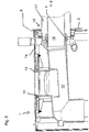
Fig. 5 einen Querschnitt durch das erfindungsgemäße Heizgerät.
-
Fig. 1 an inventive heater from the front, -
Fig. 2 the same heater according to the invention from behind, -
Fig. 3 the heater according to the invention during assembly to the on-wall wall bracket, -
Fig. 4 a section fromFIG. 3 such as -
Fig. 5 a cross section through the heater according to the invention.
Die
Zur Montage des Heizgerätes muss zunächst festgelegt werden, ob ein Abgas-Anschluss nach hinten oder nach oben gewünscht ist. Bei einem Anschluss nach oben wird der rückseitige Anschluss 15 mittels eines Deckels verschlossen und zugleich der nach oben gerichtet Anschluss geöffnet.To install the heater, it must first be determined whether an exhaust connection to the rear or to the top is desired. In an upward connection, the
Bei einem Anschluss des Frischluft-Abgas-Rohres 2 durch die Wandhalterung 3 wird die obere Öffnung mittels des Deckels 13 wie in
Hierdurch ist es nicht notwendig, zum gas- und wasserdichten Anschluss des koaxialen Frischluft-Abgas-Rohres 2 das Gehäuse 14 des Heizgerätes 1 zu öffnen. Ein weiterer Vorteil des erfindungsgemäßen Heizgeräts 1 ist, dass auch an schwer zugänglichen Stellen eine einfache Montage möglich ist.As a result, it is not necessary to open the
Claims (5)
- Combination of a heating device (1) with a wall mount (3), wherein the heating device (1) has a housing (14) and a rear connection point (15) for a coaxial fresh air exhaust gas pipe (2), consisting of an inner exhaust gas pipe (10) and an outer fresh air pipe (11), wherein the heating device (1) has rear mounts for a coaxial fresh air exhaust gas pipe (2) and the wall mount (3) has an opening for a coaxial fresh air exhaust gas pipe (2), characterised in that on the upper edge of the wall mount (3) there is a mounting strip (4) and the heating device (1) on its rear upper edge has a holding strip (5) corresponding with the latter. and the coaxial fresh air exhaust gas pipe (2) is fixed by means of a pipe clamp (9) with threaded pin (8) to the wall mount.
- Heating device (1) according to claim 1, characterised in that the rear mount in the heating device (1) for the coaxial fresh air exhaust gas pipe (2) has a seal (7) for sealing the exhaust gas pipe (10) and/or a seal (6) for sealing the fresh air pipe (11).
- Heating device according to claim 1 or 2, characterised in that the wall mount (3) comprises means for fixing the coaxial fresh air exhaust gas pipe (2), preferably angled parts, which by means of a pipe clamp (9) with threaded pin (8) fix the fresh air pipe (11) of the coaxial fresh air exhaust gas pipe (2).
- Heating device (1) according to any of claims 1 to 3 heating device exhaust gas pipe (12) in the heating device (1), characterised in that the rear connection point (15) for a coaxial fresh air exhaust gas pipe (2) can be closed by a cover which can be connected to the housing (14) of the heating device (1), and the heating device exhaust gas pipe (12) in the heating device (1) has an upwardly directed opening which can be closed by means of a cover (13) connectable to the housing (14) of the heating device (1).
- Method for installing a heating device (1) with housing (14) and rear connection point (15) for a coaxial fresh air exhaust gas pipe (2), consisting of an inner exhaust pipe (10) and an outer fresh air pipe (11), on a wall mount (3), wherein the heating device (1) has rear mounts for a coaxial fresh air exhaust gas pipe (2), wherein the wall mount (3) has an opening for a coaxial fresh air exhaust gas pipe (2), wherein on the upper edge of the wall mount (3) there is a horizontal mounting strip (4) and the heating device (1) on its rear upper edge has a corresponding holding strip (5), whereby firstly the wall mount (3) is mounted on a wall (16), the coaxial fresh air exhaust gas pipe (2) is pushed by the wall (16) into the wall mount (3) and is fixed by means of a pipe clamp (9) with threaded pin (8), the heating device (1) is put at an angle with its holding strip (5) over the mounting strip (4) of the wall mount (3) and is then aligned to be perpendicular.
Applications Claiming Priority (1)
| Application Number | Priority Date | Filing Date | Title |
|---|---|---|---|
| DE200620008322 DE202006008322U1 (en) | 2006-05-26 | 2006-05-26 | Flue for wall mounted heater especially water heater has a coaxial exhaust and fresh air duct with connection at rear or on top of housing |
Publications (2)
| Publication Number | Publication Date |
|---|---|
| EP1860385A1 EP1860385A1 (en) | 2007-11-28 |
| EP1860385B1 true EP1860385B1 (en) | 2018-07-18 |
Family
ID=36974131
Family Applications (1)
| Application Number | Title | Priority Date | Filing Date |
|---|---|---|---|
| EP07009876.9A Active EP1860385B1 (en) | 2006-05-26 | 2007-05-18 | Heating device with rear connection for a coaxial fresh air-exhaust gas pipe |
Country Status (4)
| Country | Link |
|---|---|
| EP (1) | EP1860385B1 (en) |
| DE (1) | DE202006008322U1 (en) |
| ES (1) | ES2690567T3 (en) |
| TR (1) | TR201814663T4 (en) |
Families Citing this family (3)
| Publication number | Priority date | Publication date | Assignee | Title |
|---|---|---|---|---|
| IT1392764B1 (en) * | 2009-01-28 | 2012-03-16 | Fonderie Sime S P A | BOILER STRUCTURE PARTICULARLY FOR HOUSEHOLD USE |
| DE102012011980A1 (en) * | 2012-06-16 | 2013-12-19 | Vaillant Gmbh | Exhaust adapter for a heater with recuperator |
| CA3107299A1 (en) | 2020-01-31 | 2021-07-31 | Rinnai America Corporation | Vent attachment for a tankless water heater |
Family Cites Families (6)
| Publication number | Priority date | Publication date | Assignee | Title |
|---|---|---|---|---|
| GB157868A (en) * | 1917-05-06 | 1921-09-22 | Sulzer Ag | Improvements in or relating to boilers for heating apparatus |
| GB1355055A (en) | 1970-10-16 | 1974-05-30 | Kayanson Engs Ltd | Improvements in or relating to flue outlets for stoves and boilers |
| DE7812645U1 (en) * | 1978-04-26 | 1979-10-04 | Robert Bosch Gmbh, 7000 Stuttgart | GAS HEATED WATER HEATER |
| FR2573507B1 (en) | 1984-11-19 | 1987-04-30 | Auer Soc Ind | DEVICE FOR CONNECTING TO THE OUTSIDE OF A CONSTRUCTION A WATERPROOF GAS-OPERATING APPARATUS |
| DE19505053C2 (en) * | 1995-02-15 | 1997-11-20 | Bosch Siemens Hausgeraete | Water heater |
| FR2814797B1 (en) * | 2000-09-29 | 2003-10-10 | Leblanc Sa E L M | IMPROVEMENTS IN OR RELATING TO HEATERS SUCH AS WALL-MOUNTED SUCTION CUPS |
-
2006
- 2006-05-26 DE DE200620008322 patent/DE202006008322U1/en not_active Expired - Lifetime
-
2007
- 2007-05-18 ES ES07009876.9T patent/ES2690567T3/en active Active
- 2007-05-18 EP EP07009876.9A patent/EP1860385B1/en active Active
- 2007-05-18 TR TR2018/14663T patent/TR201814663T4/en unknown
Non-Patent Citations (1)
| Title |
|---|
| None * |
Also Published As
| Publication number | Publication date |
|---|---|
| EP1860385A1 (en) | 2007-11-28 |
| TR201814663T4 (en) | 2018-11-21 |
| DE202006008322U1 (en) | 2006-08-24 |
| ES2690567T3 (en) | 2018-11-21 |
Similar Documents
| Publication | Publication Date | Title |
|---|---|---|
| DE102006053208B4 (en) | wall box | |
| EP1860385B1 (en) | Heating device with rear connection for a coaxial fresh air-exhaust gas pipe | |
| DE102008004790A1 (en) | Refrigerant compressor arrangement for use in e.g. refrigerator, has housing section and line section overlapping with each other in longitudinal direction of intake port and connected with each other by shaft region with radial shaft | |
| EP1329562A3 (en) | Floor drain | |
| EP2885542B1 (en) | Blower device with integrated manifold for a gas burner | |
| EP2852794B1 (en) | Gas-heated cooking device | |
| EP2307830B1 (en) | Household appliance fitted with a cap for covering a journal | |
| DE102010001089A1 (en) | Insulation cabinet for retaining house water distribution station, has rear part and/or front part with side wall apertures for input terminal or spacer attached to input terminal and/or side panel or ceiling aperture for output terminals | |
| EP3168375B1 (en) | Wall fitting | |
| EP2119970A2 (en) | Mounting system for fitting a housing of an extractor hood which can be attached to a wall and method for attaching such a housing | |
| DE19533183C2 (en) | Quick release device for coupling an exhaust pipe to an exhaust pipe | |
| DE102008059936A1 (en) | Impeller housing of an exhaust gas turbocharger with a separate housing wall | |
| EP1582813A2 (en) | Flue gas system with a connection to a flue gas conduit | |
| WO2007006278A1 (en) | Motor vehicle heating system and exhaust line leadthrough | |
| DE202009006040U1 (en) | End fittings | |
| EP1677043B1 (en) | Connecting and lead-through device | |
| DE102010007318A1 (en) | Wall box i.e. air circulation box, for use in building wall to drive off exhaust air from kitchen, has cap held in open position until airflow falls below threshold value, where cap tilts back into closing position due to dead weight of cap | |
| EP1933089A2 (en) | Soot protection flap | |
| EP1671710B1 (en) | Suction and filtering device | |
| EP0982547B1 (en) | Extraction hood connecting device | |
| DE102012016349A1 (en) | Ventilation device arrangement | |
| AT510038B1 (en) | EQUIPMENT FOR CHIMNEY OR SMOKE EXHAUST | |
| DE202012102861U1 (en) | Protective tubing and protective tube system for receiving external cables to buildings | |
| DE202009010770U1 (en) | Shower device with a solar panel | |
| EP1180644B1 (en) | Exhaust pipe connection for heating apparatus |
Legal Events
| Date | Code | Title | Description |
|---|---|---|---|
| PUAI | Public reference made under article 153(3) epc to a published international application that has entered the european phase |
Free format text: ORIGINAL CODE: 0009012 |
|
| AK | Designated contracting states |
Kind code of ref document: A1 Designated state(s): AT BE BG CH CY CZ DE DK EE ES FI FR GB GR HU IE IS IT LI LT LU LV MC MT NL PL PT RO SE SI SK TR |
|
| AX | Request for extension of the european patent |
Extension state: AL BA HR MK YU |
|
| 17P | Request for examination filed |
Effective date: 20071213 |
|
| AKX | Designation fees paid |
Designated state(s): AT BE BG CH CY CZ DE DK EE ES FI FR GB GR HU IE IS IT LI LT LU LV MC MT NL PL PT RO SE SI SK TR |
|
| STAA | Information on the status of an ep patent application or granted ep patent |
Free format text: STATUS: EXAMINATION IS IN PROGRESS |
|
| 17Q | First examination report despatched |
Effective date: 20161216 |
|
| GRAP | Despatch of communication of intention to grant a patent |
Free format text: ORIGINAL CODE: EPIDOSNIGR1 |
|
| STAA | Information on the status of an ep patent application or granted ep patent |
Free format text: STATUS: GRANT OF PATENT IS INTENDED |
|
| RIC1 | Information provided on ipc code assigned before grant |
Ipc: F24H 9/06 20060101AFI20180201BHEP Ipc: F23J 13/04 20060101ALI20180201BHEP |
|
| INTG | Intention to grant announced |
Effective date: 20180220 |
|
| GRAS | Grant fee paid |
Free format text: ORIGINAL CODE: EPIDOSNIGR3 |
|
| GRAA | (expected) grant |
Free format text: ORIGINAL CODE: 0009210 |
|
| STAA | Information on the status of an ep patent application or granted ep patent |
Free format text: STATUS: THE PATENT HAS BEEN GRANTED |
|
| AK | Designated contracting states |
Kind code of ref document: B1 Designated state(s): AT BE BG CH CY CZ DE DK EE ES FI FR GB GR HU IE IS IT LI LT LU LV MC MT NL PL PT RO SE SI SK TR |
|
| REG | Reference to a national code |
Ref country code: GB Ref legal event code: FG4D Free format text: NOT ENGLISH |
|
| REG | Reference to a national code |
Ref country code: CH Ref legal event code: EP |
|
| REG | Reference to a national code |
Ref country code: IE Ref legal event code: FG4D Free format text: LANGUAGE OF EP DOCUMENT: GERMAN |
|
| REG | Reference to a national code |
Ref country code: DE Ref legal event code: R096 Ref document number: 502007016287 Country of ref document: DE |
|
| REG | Reference to a national code |
Ref country code: AT Ref legal event code: REF Ref document number: 1019794 Country of ref document: AT Kind code of ref document: T Effective date: 20180815 |
|
| REG | Reference to a national code |
Ref country code: ES Ref legal event code: FG2A Ref document number: 2690567 Country of ref document: ES Kind code of ref document: T3 Effective date: 20181121 Ref country code: NL Ref legal event code: MP Effective date: 20180718 |
|
| REG | Reference to a national code |
Ref country code: LT Ref legal event code: MG4D |
|
| PG25 | Lapsed in a contracting state [announced via postgrant information from national office to epo] |
Ref country code: NL Free format text: LAPSE BECAUSE OF FAILURE TO SUBMIT A TRANSLATION OF THE DESCRIPTION OR TO PAY THE FEE WITHIN THE PRESCRIBED TIME-LIMIT Effective date: 20180718 |
|
| REG | Reference to a national code |
Ref country code: SK Ref legal event code: T3 Ref document number: E 28531 Country of ref document: SK |
|
| PG25 | Lapsed in a contracting state [announced via postgrant information from national office to epo] |
Ref country code: PL Free format text: LAPSE BECAUSE OF FAILURE TO SUBMIT A TRANSLATION OF THE DESCRIPTION OR TO PAY THE FEE WITHIN THE PRESCRIBED TIME-LIMIT Effective date: 20180718 Ref country code: LT Free format text: LAPSE BECAUSE OF FAILURE TO SUBMIT A TRANSLATION OF THE DESCRIPTION OR TO PAY THE FEE WITHIN THE PRESCRIBED TIME-LIMIT Effective date: 20180718 Ref country code: IS Free format text: LAPSE BECAUSE OF FAILURE TO SUBMIT A TRANSLATION OF THE DESCRIPTION OR TO PAY THE FEE WITHIN THE PRESCRIBED TIME-LIMIT Effective date: 20181118 Ref country code: FI Free format text: LAPSE BECAUSE OF FAILURE TO SUBMIT A TRANSLATION OF THE DESCRIPTION OR TO PAY THE FEE WITHIN THE PRESCRIBED TIME-LIMIT Effective date: 20180718 Ref country code: GR Free format text: LAPSE BECAUSE OF FAILURE TO SUBMIT A TRANSLATION OF THE DESCRIPTION OR TO PAY THE FEE WITHIN THE PRESCRIBED TIME-LIMIT Effective date: 20181019 Ref country code: SE Free format text: LAPSE BECAUSE OF FAILURE TO SUBMIT A TRANSLATION OF THE DESCRIPTION OR TO PAY THE FEE WITHIN THE PRESCRIBED TIME-LIMIT Effective date: 20180718 Ref country code: BG Free format text: LAPSE BECAUSE OF FAILURE TO SUBMIT A TRANSLATION OF THE DESCRIPTION OR TO PAY THE FEE WITHIN THE PRESCRIBED TIME-LIMIT Effective date: 20181018 |
|
| PG25 | Lapsed in a contracting state [announced via postgrant information from national office to epo] |
Ref country code: LV Free format text: LAPSE BECAUSE OF FAILURE TO SUBMIT A TRANSLATION OF THE DESCRIPTION OR TO PAY THE FEE WITHIN THE PRESCRIBED TIME-LIMIT Effective date: 20180718 |
|
| REG | Reference to a national code |
Ref country code: DE Ref legal event code: R097 Ref document number: 502007016287 Country of ref document: DE |
|
| PG25 | Lapsed in a contracting state [announced via postgrant information from national office to epo] |
Ref country code: CZ Free format text: LAPSE BECAUSE OF FAILURE TO SUBMIT A TRANSLATION OF THE DESCRIPTION OR TO PAY THE FEE WITHIN THE PRESCRIBED TIME-LIMIT Effective date: 20180718 Ref country code: RO Free format text: LAPSE BECAUSE OF FAILURE TO SUBMIT A TRANSLATION OF THE DESCRIPTION OR TO PAY THE FEE WITHIN THE PRESCRIBED TIME-LIMIT Effective date: 20180718 Ref country code: EE Free format text: LAPSE BECAUSE OF FAILURE TO SUBMIT A TRANSLATION OF THE DESCRIPTION OR TO PAY THE FEE WITHIN THE PRESCRIBED TIME-LIMIT Effective date: 20180718 |
|
| PLBE | No opposition filed within time limit |
Free format text: ORIGINAL CODE: 0009261 |
|
| STAA | Information on the status of an ep patent application or granted ep patent |
Free format text: STATUS: NO OPPOSITION FILED WITHIN TIME LIMIT |
|
| PG25 | Lapsed in a contracting state [announced via postgrant information from national office to epo] |
Ref country code: DK Free format text: LAPSE BECAUSE OF FAILURE TO SUBMIT A TRANSLATION OF THE DESCRIPTION OR TO PAY THE FEE WITHIN THE PRESCRIBED TIME-LIMIT Effective date: 20180718 |
|
| 26N | No opposition filed |
Effective date: 20190423 |
|
| PG25 | Lapsed in a contracting state [announced via postgrant information from national office to epo] |
Ref country code: SI Free format text: LAPSE BECAUSE OF FAILURE TO SUBMIT A TRANSLATION OF THE DESCRIPTION OR TO PAY THE FEE WITHIN THE PRESCRIBED TIME-LIMIT Effective date: 20180718 |
|
| REG | Reference to a national code |
Ref country code: CH Ref legal event code: PL |
|
| PG25 | Lapsed in a contracting state [announced via postgrant information from national office to epo] |
Ref country code: CH Free format text: LAPSE BECAUSE OF NON-PAYMENT OF DUE FEES Effective date: 20190531 Ref country code: MC Free format text: LAPSE BECAUSE OF FAILURE TO SUBMIT A TRANSLATION OF THE DESCRIPTION OR TO PAY THE FEE WITHIN THE PRESCRIBED TIME-LIMIT Effective date: 20180718 Ref country code: LI Free format text: LAPSE BECAUSE OF NON-PAYMENT OF DUE FEES Effective date: 20190531 |
|
| REG | Reference to a national code |
Ref country code: BE Ref legal event code: MM Effective date: 20190531 |
|
| PG25 | Lapsed in a contracting state [announced via postgrant information from national office to epo] |
Ref country code: LU Free format text: LAPSE BECAUSE OF NON-PAYMENT OF DUE FEES Effective date: 20190518 |
|
| PG25 | Lapsed in a contracting state [announced via postgrant information from national office to epo] |
Ref country code: IE Free format text: LAPSE BECAUSE OF NON-PAYMENT OF DUE FEES Effective date: 20190518 |
|
| PG25 | Lapsed in a contracting state [announced via postgrant information from national office to epo] |
Ref country code: BE Free format text: LAPSE BECAUSE OF NON-PAYMENT OF DUE FEES Effective date: 20190531 |
|
| PG25 | Lapsed in a contracting state [announced via postgrant information from national office to epo] |
Ref country code: PT Free format text: LAPSE BECAUSE OF FAILURE TO SUBMIT A TRANSLATION OF THE DESCRIPTION OR TO PAY THE FEE WITHIN THE PRESCRIBED TIME-LIMIT Effective date: 20181118 |
|
| REG | Reference to a national code |
Ref country code: AT Ref legal event code: MM01 Ref document number: 1019794 Country of ref document: AT Kind code of ref document: T Effective date: 20190518 |
|
| PG25 | Lapsed in a contracting state [announced via postgrant information from national office to epo] |
Ref country code: AT Free format text: LAPSE BECAUSE OF NON-PAYMENT OF DUE FEES Effective date: 20190518 |
|
| PG25 | Lapsed in a contracting state [announced via postgrant information from national office to epo] |
Ref country code: CY Free format text: LAPSE BECAUSE OF FAILURE TO SUBMIT A TRANSLATION OF THE DESCRIPTION OR TO PAY THE FEE WITHIN THE PRESCRIBED TIME-LIMIT Effective date: 20180718 |
|
| PG25 | Lapsed in a contracting state [announced via postgrant information from national office to epo] |
Ref country code: HU Free format text: LAPSE BECAUSE OF FAILURE TO SUBMIT A TRANSLATION OF THE DESCRIPTION OR TO PAY THE FEE WITHIN THE PRESCRIBED TIME-LIMIT; INVALID AB INITIO Effective date: 20070518 Ref country code: MT Free format text: LAPSE BECAUSE OF FAILURE TO SUBMIT A TRANSLATION OF THE DESCRIPTION OR TO PAY THE FEE WITHIN THE PRESCRIBED TIME-LIMIT Effective date: 20180718 |
|
| PGFP | Annual fee paid to national office [announced via postgrant information from national office to epo] |
Ref country code: IT Payment date: 20230529 Year of fee payment: 17 Ref country code: FR Payment date: 20230523 Year of fee payment: 17 Ref country code: ES Payment date: 20230601 Year of fee payment: 17 Ref country code: DE Payment date: 20230425 Year of fee payment: 17 |
|
| PGFP | Annual fee paid to national office [announced via postgrant information from national office to epo] |
Ref country code: TR Payment date: 20230502 Year of fee payment: 17 Ref country code: SK Payment date: 20230426 Year of fee payment: 17 |
|
| PGFP | Annual fee paid to national office [announced via postgrant information from national office to epo] |
Ref country code: GB Payment date: 20230425 Year of fee payment: 17 |