EP1860309B1 - Verbesserungen im Zusammenhang mit der Steuerung von Brennstoffinjektoren - Google Patents
Verbesserungen im Zusammenhang mit der Steuerung von Brennstoffinjektoren Download PDFInfo
- Publication number
- EP1860309B1 EP1860309B1 EP07252045A EP07252045A EP1860309B1 EP 1860309 B1 EP1860309 B1 EP 1860309B1 EP 07252045 A EP07252045 A EP 07252045A EP 07252045 A EP07252045 A EP 07252045A EP 1860309 B1 EP1860309 B1 EP 1860309B1
- Authority
- EP
- European Patent Office
- Prior art keywords
- differential voltage
- charge
- voltage level
- stack
- actuator
- Prior art date
- Legal status (The legal status is an assumption and is not a legal conclusion. Google has not performed a legal analysis and makes no representation as to the accuracy of the status listed.)
- Active
Links
- 239000000446 fuel Substances 0.000 title claims abstract description 38
- 238000002347 injection Methods 0.000 claims abstract description 50
- 239000007924 injection Substances 0.000 claims abstract description 50
- 238000000034 method Methods 0.000 claims abstract description 33
- 238000013500 data storage Methods 0.000 claims description 4
- 238000004590 computer program Methods 0.000 claims description 3
- 238000012886 linear function Methods 0.000 claims description 2
- 239000003990 capacitor Substances 0.000 description 8
- 238000006073 displacement reaction Methods 0.000 description 8
- KHESEVVLJIFTFE-UHFFFAOYSA-N CN(C1=CC=C2C=C(C(=NC2=C1)N)C1=CN(C2=CC=CC=C12)C)C Chemical compound CN(C1=CC=C2C=C(C(=NC2=C1)N)C1=CN(C2=CC=CC=C12)C)C KHESEVVLJIFTFE-UHFFFAOYSA-N 0.000 description 5
- 230000006870 function Effects 0.000 description 5
- 230000008929 regeneration Effects 0.000 description 5
- 238000011069 regeneration method Methods 0.000 description 5
- 238000011217 control strategy Methods 0.000 description 4
- 238000002485 combustion reaction Methods 0.000 description 3
- 238000012544 monitoring process Methods 0.000 description 3
- 238000005538 encapsulation Methods 0.000 description 2
- 230000001681 protective effect Effects 0.000 description 2
- 230000002411 adverse Effects 0.000 description 1
- 230000003247 decreasing effect Effects 0.000 description 1
- 230000001419 dependent effect Effects 0.000 description 1
- 230000001627 detrimental effect Effects 0.000 description 1
- 230000000694 effects Effects 0.000 description 1
- 238000004146 energy storage Methods 0.000 description 1
- 230000007704 transition Effects 0.000 description 1
Images

Classifications
-
- F—MECHANICAL ENGINEERING; LIGHTING; HEATING; WEAPONS; BLASTING
- F02—COMBUSTION ENGINES; HOT-GAS OR COMBUSTION-PRODUCT ENGINE PLANTS
- F02D—CONTROLLING COMBUSTION ENGINES
- F02D41/00—Electrical control of supply of combustible mixture or its constituents
- F02D41/20—Output circuits, e.g. for controlling currents in command coils
- F02D41/2096—Output circuits, e.g. for controlling currents in command coils for controlling piezoelectric injectors
-
- F—MECHANICAL ENGINEERING; LIGHTING; HEATING; WEAPONS; BLASTING
- F02—COMBUSTION ENGINES; HOT-GAS OR COMBUSTION-PRODUCT ENGINE PLANTS
- F02D—CONTROLLING COMBUSTION ENGINES
- F02D2200/00—Input parameters for engine control
- F02D2200/02—Input parameters for engine control the parameters being related to the engine
- F02D2200/06—Fuel or fuel supply system parameters
- F02D2200/0602—Fuel pressure
-
- F—MECHANICAL ENGINEERING; LIGHTING; HEATING; WEAPONS; BLASTING
- F02—COMBUSTION ENGINES; HOT-GAS OR COMBUSTION-PRODUCT ENGINE PLANTS
- F02D—CONTROLLING COMBUSTION ENGINES
- F02D41/00—Electrical control of supply of combustible mixture or its constituents
- F02D41/30—Controlling fuel injection
- F02D41/38—Controlling fuel injection of the high pressure type
- F02D41/3809—Common rail control systems
Definitions
- the invention relates to a method of operating a piezoelectric fuel injector. More specifically, the invention relates to a method of operating a piezoelectric fuel injector in order to improve its operational life. The invention also relates to a drive arrangement for implementing such a method.
- a piezoelectric injector In an internal combustion engine, it is known to deliver fuel into the cylinders of the engine by means of a fuel injector.
- a fuel injector that permits precise metering of fuel delivery is a so-called 'piezoelectric injector'.
- a piezoelectric injector includes a piezoelectric actuator that is operable to control an injection nozzle.
- the injection nozzle houses an injector valve needle which is movable relative to a valve needle seating under the control of the actuator.
- a hydraulic amplifier is situated between the actuator and the needle such that axial movement of the actuator causes an amplified axial movement of the needle.
- the valve needle is either caused to disengage the valve seat, in which case fuel is delivered into the associated engine cylinder through outlets provided in a tip of the nozzle, or is caused to engage the valve seat, in which case fuel delivery through the outlets is prevented.
- the amount of charge is varied causing the valve needle to move between closed and open positions.
- the amount of charge applied to and removed from the piezoelectric actuator can be controlled in one of two ways.
- a current is driven into or out of the piezoelectric actuator for a period of time so as to remove or add, respectively, a demanded charge to or from the stack, respectively.
- a voltage control method a current is driven into or out of the piezoelectric actuator until the voltage across the piezoelectric actuator reaches a demanded level. In either case, the voltage across the piezoelectric actuator changes as the level of charge on the piezoelectric actuator varies, and vice versa.
- the drive circuit In order to initiate an injection of fuel, the drive circuit causes the differential voltage across the actuator terminals to transition from a high level at which no fuel delivery occurs to a relatively low level to initiate fuel delivery.
- An injector responsive to this drive waveform is referred to as a 'de-energise to inject' injector.
- the voltage across the de-energise-to-inject injector is therefore relatively high and when in an injecting state the voltage across the actuator is relatively low.
- a method of operating a fuel injector including a piezoelectric actuator having a stack of piezoelectric elements comprising applying a discharge current to the actuator for a discharge period so as to discharge the stack from a first differential voltage level across the stack to a second differential voltage level across the stack so as to initiate an injection event, and applying a charge current to the actuator for a charge period so as to charge the stack from the second differential voltage level to a third differential voltage level so as to terminate the injection event.
- At least one engine parameter of the injection event is determined (e.g. measured) prior to applying the charge current to the actuator and the third differential voltage level is selected in dependence on the at least one engine parameter.
- the at least one engine parameter is determined by measuring the at least one engine parameter prior to the start of the discharge period (discharge phase) of an injection event and the subsequent charging phase of that injection event is then adjusted accordingly.
- the at least one engine parameter is determined by measuring the at least one engine parameter during the discharge period or after the discharge period, but still prior to the subsequent charge period.
- the invention selects the third differential voltage level to which the stack is recharged at the end of an injection event in dependence on one or more engine parameters.
- the third differential voltage level across the stack may be varied as a function of fuel pressure within the common rail of the engine (referred to as rail pressure). For example, if fuel pressure is relatively low, the third differential voltage level to which the stack is recharged to terminate the injection event is set at a lower level than if fuel pressure is relatively high.
- the injector includes a valve needle which is operable by means of the piezoelectric actuator to engage and disengage from a valve needle seating so as to control the injection of fuel into the engine.
- the magnitude of the voltage drop across the stack determines the extent of displacement of the stack and, hence, the extent of displacement of the valve needle. If the voltage across the terminals is reduced, the magnitude of actuator displacement will also be reduced. To get the same amount of needle lift you need more actuator displacement at high rail pressures than at low pressures because the forces trying to close the needle increase with pressure. Therefore, implementing the method of the invention at low rail pressures does not compromise needle lift to the detriment of injector operation, but does allow the injector to be operated more efficiently.
- the stack can be recharged to a lower differential voltage level (the third differential voltage level) than the first differential voltage level (the differential voltage at the start of discharge) without compromising injector performance.
- the actuator is subjected to a reduced stress when in a non-injecting state which benefits injector life.
- the permeation of ionic species into the actuator though the protective actuator encapsulation will tend to be reduced when there is a lower voltage drop across the stack.
- the third differential voltage level may be varied as a function of engine load, engine speed or throttle position, for example, or a combination of more than one of the aforementioned engine parameters.
- the method includes selecting a charge time for which the charge current is applied so as to achieve the third differential voltage level. This is carried out subsequent to the selection of the third differential voltage level in dependence on the one or more engine parameters.
- the third differential voltage level to which the stack is recharged can be adjusted by adjusting the level of a voltage source (e.g. a high voltage rail) for applying a differential voltage across the stack.
- a voltage source e.g. a high voltage rail
- the third differential voltage level may be selected from a look-up table or data map of calibration data.
- the third differential voltage level may be a step-change function of the at least one engine parameter or may be a linear function of the at least one engine parameter.
- a drive arrangement for example forming part of a control unit, for a fuel injector including a piezoelectric actuator having a stack of piezoelectric elements, the drive arrangement comprising a first element(s) for applying a discharge current to the actuator for a discharge period so as to discharge the stack from a first differential voltage level across the stack to a second differential voltage level across the stack so as to initiate an injection event, and a second element(s) for applying a charge current the actuator for a charge period so as to charge the stack from the second differential voltage level to a third differential voltage level so as to terminate the injection event.
- a third element(s) determines at least one engine parameter prior to applying the charge current to the actuator such that the third differential voltage level to which the stack is charged is selected in dependence on the at least one engine parameter.
- the first, second and third elements of the drive arrangement may be separate elements, or may be integral with one another.
- the elements may be part of the same circuit board.
- a computer program product comprising at least one computer program software portion which, when executed in an executing environment, is operable to implement the method of the first aspect of the invention.
- a data storage medium having the or each computer software portion of the third aspect of the invention stored thereon.
- a microcomputer provided with the data storage medium of the fourth aspect of the invention.
- a piezoelectric injector 2 includes a piezoelectric actuator 4 having a stack of piezoelectric elements (not identified).
- the piezoelectric actuator 4 is operable to control the position of an injector valve needle 6 relative to a valve needle seating 8.
- the valve needle 6 is either caused to disengage the valve needle seating 8, in which case fuel is delivered into an associated combustion chamber (not shown) through a set of nozzle outlets 10, or is caused to engage the valve needle seating 8, in which case fuel delivery is prevented.
- the piezoelectric injector 2 is controlled by an injector control unit (ICU) 20 that forms an integral part of an engine control unit (ECU) 22.
- the ECU 22 continuously monitors a plurality of engine parameters 24 and feeds an engine power requirement signal to the ICU 20.
- the ICU 20 calculates a demanded injection event sequence to provide the required power for the engine and operates an injector drive circuit 26 of the ECU 22 accordingly.
- the injector drive circuit 26 causes a current to be applied to or removed from the injector to achieve the demanded injection event sequence.
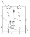
- the injector drive circuit 26 is shown in more detail in Figure 2 .
- the drive circuit 26 includes a high voltage rail V HI and a low voltage rail V LO , at approximately +250 and +50 V respectively, and a ground potential rail GND.
- a first energy storage capacitor C1 is connected between the high voltage rail V HI and a middle current path 32, and a second storage capacitor C2 is connected between the middle current path 32 and the ground potential rail GND.
- An inductor 34 is connected in the middle current path 32.
- the voltage across the first storage capacitor is V C1 and the voltage across the second storage capacitor is V C2 .
- An injector bank network 30 comprising first and second piezoelectric injectors, INJ1 and INJ2 respectively, is connected between the high and low voltage rails, V HI and V LO , of the injector drive circuit and in series with the inductor 34.
- a differential voltage of approximately +200V is applied across the terminals of the first and second injectors INJ1, INJ2. In the non-injecting state this differential voltage is the difference in voltage between the voltage rails V HI and V LO .
- a diode D1 is provided between the middle current path 32 on the injector side of the inductor L1 and the high voltage rail V HI , and another diode D2 is provided between the ground potential rail GND and the middle current path 32, again, on the injector side of the inductor L1.
- the diode D1 provides a 'voltage clamping effect' for a selected injector INJ1 or INJ2 at the end of its charge phase and prevents the injector INJ1, INJ2 from being driven to voltages higher than V C1 .
- the diode D2 provides a recirculation path for current flow during the discharge phase of operation, as described in further detail below.
- the injector bank network 30 further includes first and second injector select switches ISQ1, ISQ2.
- the injector drive circuit 26 also includes an injector charge select switch Q1 and an injector discharge select switch Q2 by which means either of the injectors INJ1, INJ2 may be selected for charge or discharge operation.
- the injector drive circuit 26 illustrated in Figure 2 is of a type known in the prior art and is described in further detail in, for example, the following European patent applications: EP 06255815.0 , EP 06254039.8 and EP 06253619.8 .
- EP 06255815.0 By controlling the injector select switches ISQ1, ISQ2, the charge switch Q1, and the discharge switch Q2, it is possible to drive a varying current through the injectors INJ1, INJ2, for a required time, such that the actuator of a selected injector is charged/discharged, and fuel delivery is controlled accordingly.
- the injector drive circuit 26 is shown in Figure 2 as forming an integral part of the ECU 22, this need not be the case and the injector drive circuit 26 may be a separate unit from the ECU 22.
- the first injector select switch ISQ1 When in a non-injecting state the first injector select switch ISQ1 is open and both the charge and discharge select switches Q1, Q2 are open. During this stage of operation the differential voltage across the terminals of the actuator 4 is at a first differential voltage level of around 200V.
- the first injector select switch ISQ1 In order to cause the first injector INJ1 to deliver fuel, the first injector select switch ISQ1 is activated (closed) and the injector discharge select switch Q2 is activated (closed). This causes charge to flow out of the injector INJ1, through the inductor L1 and the discharge select switch Q2 to the ground potential rail GND.
- the injector drive circuit 26 determines, from a look-up table stored in a memory of the ECU 22, a demanded discharge time for which the discharge current is transferred from the actuator.
- the injector discharge switch ISQ1 is deactivated (opened) to terminate charge transfer.
- the differential voltage across the injector INJ1 is decreased to a relatively low, second differential voltage level.
- the second differential voltage level is between -30V and -50V.
- the differential voltage across the actuator will remain, or 'dwell', at the second differential voltage level for a relatively brief period during which the injector is injecting fuel.
- the injector charge switch Q1 is activated to cause charge to flow from the high voltage rail V HI , through the charge select switch Q1 and into the injector INJ1, thus re-establishing a differential voltage of about +200V across the terminals of the injector INJ1. This is referred to as the charge phase.
- the time for which the injector charge switch Q1 is activated to cause the voltage across the injector to increase back to the initial differential voltage level is based on the discharge time of the previous discharge phase so as to ensure that the actuator is fully charged at the end of the injection event.
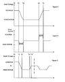
- Figure 3 represents the voltage profile of a typical injection event comprising a single injection of fuel, as described above.
- Figure 4 represents the drive current profile corresponding to the voltage profile in Figure 3 .
- a discharge phase is initiated by driving a PWM (pulse width modulated) discharge current, at RMS current level I DISCHARGE , through the injector for the time period T1 to T2.
- the discharge current is turned off at the end of the discharge phase, at time T2, and the injector remains in the dwell phase until time T3.
- the injector is injecting fuel.
- a PWM charge current at RMS current level I CHARGE , is supplied to the injector for a charge phase, until time T4 when the charge current I CHARGE is turned off and the injector is returned to its non-injecting state.
- the injector spends the majority of its service life in a non-injecting state, using the aforementioned method of operation it spends the majority of its service life with a high differential voltage across the actuator terminals. As discussed previously, this is prejudicial to injector performance.
- the method of the invention is implemented by the drive circuit in Figures 1 and 2 but improves on the aforementioned method by recognising that, in certain circumstances, the differential voltage across the actuator terminals need not be returned, at the end of the charging phase, to the high differential voltage level of the initial, non-injecting state.
- the injector is in a non-injecting state in which the differential voltage across the actuator is around +200V.
- the pressure of fuel in the common rail (rail pressure) is determined from a rail pressure sensor signal provided to the ECU 22.
- a discharge current I DISCHARGE is removed from the actuator, between T1 and T2, so as to remove the demanded amount of charge from the actuator, thereby reducing the differential voltage across the actuator to a relatively low voltage level of around -30V.
- the differential voltage may be reduced to as much as -50V or, for smaller values of needle lift, may be reduced to around 0V.
- the discharge current I DISCHARGE is determined by, for example, rail pressure and stack temperature.
- the discharge current I DISCHARGE is removed and the actuator remains in the dwell phase until time T3.
- the injector is injecting fuel. If the rail pressure measured at the start of the injection event is below a predetermined level, the ECU 22 determines that it is not necessary to re-establish the initial, relatively high differential voltage across the actuator 4 at the end of the charge phase. Instead, the charge current, I CHARGE , is only supplied to the actuator for a reduced time period (i.e. T3 to T4') so that the differential voltage across the actuator at the end of the charge phase (i.e. at the end of injection) is lower than the differential voltage at the start of the discharge phase (i.e.
- the ECU 22 selects an appropriate, reduced charging time from data stored in its memory by first determining (from a look-up table or data map) the differential voltage that is required across the actuator 4 for the measured rail pressure. The ECU 22 then determines (from a look-up table or data map) the appropriate charging time that will result in this differential voltage across the actuator. In an open loop charge control strategy, the charge current is applied for the selected charging time to achieve the desired differential voltage. As the charge current is not controlled on voltage, at the end of the charge phase further current pulses are applied to the actuator to correct the differential voltage level, if necessary.
- the actuator is then operated between a reduced differential voltage at the start of injection and the same, reduced differential voltage at the end of injection, as indicated by the injection event following time T4' in Figure 5 .
- the charge current I CHARGE is applied to the actuator, under the control of the ECU 22, for an increased time period (e.g. equivalent to T3 to T4 in Figure 3 ) so as to re-establish the initial high differential voltage level of around +200V across the actuator 4 at the end of the charging phase.
- the differential voltage across the injector is varied in a step-change manner through appropriate adjustment of the charge time.
- the charge time (T3 to T4') is selected so that the differential voltage across the actuator at the end of the injection event is +180V.
- the charge time (T3 to T4') is selected so that the differential voltage across the actuator at the end of the injection event is +200V.
- the ECU 22 performs the task of monitoring the rail pressure and selecting the differential voltage across the injector, and hence the charge time, depending on the rail pressure.
- the benefit of the invention is that the actuator spends a reduced period of time with a high differential voltage across the actuator terminals, so that the actuator is subjected to a reduced stress.
- actuator displacement will also be reduced for a reduced voltage drop across the terminals (i.e. between non-injecting voltage and injecting voltage), at low values of rail pressure a reduced actuator displacement is required, compared to high values of rail pressure, and so valve needle lift is not affected. If rail pressure is relatively low, for example, absolute valve needle displacement is not critical to injector operation and so the stack can be recharged to a lower differential voltage without compromising injector performance.
- the differential voltage across the injector may be varied in a linear manner as a function of the rail pressure, rather than as a step-change function.
- the injector is controlled so that the differential voltage across the injector at the end of the charging phase is increased in proportion to the increase in rail pressure by adjusting the charge time (T3 to T4') appropriately.
- the ECU 22 selects an appropriate, reduced charging time from data stored in its memory by first determining (from a look-up table or data map) the differential voltage that is required across the injector for the measured rail pressure. The ECU 22 then determines (from a look-up table or data map) the appropriate charging time that will result in this differential voltage.
- a closed loop voltage control strategy may be used whereby the voltage is measured throughout the charge phase and the charging current is terminated when it is determined that the selected third differential voltage level has been achieved across the actuator.
- the value of the high voltage rail may be varied in accordance with the measured rail pressure in order to vary the differential voltage across the injector. For example, if the rail pressure just prior to an injection event is less than 500 bar, the voltage applied to the high voltage rail is set at 150V whereas if rail pressure is measured to be greater than or equal to 500 bar, the voltage applied to the high voltage rail is set at 250V. The level of the high voltage rail influences the differential voltage across the injector.
- the ECU 22 performs the task of monitoring the engine parameters and configuring the value of the high voltage rail.
- our co-pending European patent application EP 06253619.8 describes a method in which the voltage on the first charge storage capacitor, V C1 , can be varied through use of a regeneration switch circuitry (not shown) forming part of the drive circuit 26.
- the regeneration switch circuitry comprises a regeneration switch which is operable by the ECU 22 to vary the charge that is returned to the first storage capacitor C1 during a regeneration phase which occurs at the end of an injection event.
- the charge on the first storage capacitor C1 determines the level of the high voltage rail, V HI .
- one way of adjusting the level of the high voltage rail V HI in accordance with the present invention is to adjust the time for which the regeneration circuitry is operated, so as to charge the storage capacitor C1, and hence to set the high voltage rail V HI , to a level to which it is appropriate to recharge the stack, given the measured rail pressure.
- the high voltage rail may be varied linearly in proportion to the measured rail pressure, rather than in a step-change manner.
Landscapes
- Engineering & Computer Science (AREA)
- Chemical & Material Sciences (AREA)
- Combustion & Propulsion (AREA)
- Mechanical Engineering (AREA)
- General Engineering & Computer Science (AREA)
- Fuel-Injection Apparatus (AREA)
- Electrical Control Of Air Or Fuel Supplied To Internal-Combustion Engine (AREA)
Claims (14)
- Verfahren zum Betreiben eines Kraftstoffinjektors (2), der einen piezoelektrischen Aktuator (4) mit einem Stapel piezoelektrischer Elemente umfasst, wobei das Verfahren umfasst:Anlegen eines Entladestroms (IDISCHARGE) an den Aktuator (4) während einer Entladeperiode derart, dass der Stapel von einem ersten differentiellen Spannungspegel an dem Stapel auf einen zweiten differentiellen Spannungspegel an dem Stapel entladen wird, um ein Einspritzereignis einzuleiten, undAnlegen eines Ladestroms (ICHARGE) an den Aktuator (4) während einer Ladeperiode (T3 bis T4') derart, dass der Stapel von dem zweiten differentiellen Spannungspegel auf einen dritten differentiellen Spannungspegel aufgeladen wird, um das Einspritzereignis zu beenden,wobei mindestens ein Motorparameter vor dem Anlegen des Ladestroms (ICHARGE) an den Aktuator (4) ermittelt wird und der dritte differentielle Spannungspegel in Abhängigkeit von dem mindestens einen Motorparameter gewählt wird.
- Verfahren nach Anspruch 1, wobei der Schritt des Ermittelns des mindestens einen Motorparameters ein Messen des mindestens einen Motorparameters vor dem Start der Entladeperiode umfasst.
- Verfahren nach Anspruch 1, wobei der Schritt des Ermittelns des mindestens einen Motorparameters ein Messen des mindestens einen Motorparameters während der Entladeperiode umfasst.
- Verfahren nach Anspruch 1, wobei der Schritt des Ermittelns des mindestens einen Motorparameters ein Messen des mindestens einen Motorparameters nach der Entladeperiode umfasst.
- Verfahren nach einem der Ansprüche 1 bis 4, wobei der dritte differentielle Spannungspegel als eine Funktion des Kraftstoffdrucks in einem Common Rail des Motors gewählt wird.
- Verfahren nach einem der Ansprüche 1 bis 5, das nach dem Wählen eines dritten differentiellen Spannungspegels in Abhängigkeit von dem mindestens einen Motorparameter ein Wählen einer Ladezeit umfasst, während der der Ladestrom angelegt wird, um den gewählten dritten differentiellen Spannungspegel zu erreichen.
- Verfahren nach einem der Ansprüche 1 bis 5, das nach dem Wählen eines dritten differentiellen Spannungspegels in Abhängigkeit von dem mindestens einen Motorparameter ein Einstellen des Pegels einer Spannungsquelle (VHI) zum Anlegen einer differentiellen Spannung an den Stapel umfasst, um den gewählten dritten differentiellen Spannungspegel zu erreichen.
- Verfahren nach einem der Ansprüche 1 bis 7, wobei der dritte differentielle Spannungspegel aus einer Nachschlagetabelle oder einem Datenverzeichnis von Kalibrierungsdaten gewählt wird.
- Verfahren nach einem der Ansprüche 1 bis 8, wobei der dritte differentielle Spannungspegel eine Treppenfunktion oder eine lineare Funktion des mindestens einen Motorparameters ist.
- Verfahren nach einem der Ansprüche 1 bis 9, wobei der dritte differentielle Spannungspegel als eine Funktion der Motorlast, der Motordrehzahl und/oder der Drosselklappenstellung gewählt wird.
- Antriebsanordnung für einen Kraftstoffinjektor (2), der einen piezoelektrischen Aktuator (4) mit einem Stapel piezoelektrischer Elemente umfasst, wobei die Antriebsanordnung umfasst:ein erstes Element oder erste Elemente zum Anlegen eines Entladestroms (IDISCHARGE) an den Aktuator (4) während einer Entladeperiode derart, dass der Stapel von einem ersten differentiellen Spannungspegel an dem Stapel auf einen zweiten differentiellen Spannungspegel an dem Stapel entladen wird, um ein Einspritzereignis einzuleiten,ein zweites Element oder zweite Elemente zum Anlegen eines Ladestroms (ICHARGE) an den Aktuator (4) während einer Ladeperiode (T3 bis T4') derart, dass der Stapel von dem zweiten differentiellen Spannungspegel auf einen dritten differentiellen Spannungspegel aufgeladen wird, um das Einspritzereignis zu beenden, undein drittes Element oder dritte Elemente zum Ermitteln mindestens eines Motorparameters vor dem Anlegen des Ladestroms (ICHARGE) an den Aktuator (4) derart, dass der dritte differentielle Spannungspegel, auf welchen der Stapel aufgeladen wird, in Abhängigkeit von dem mindestens einen Motorparameter gewählt wird.
- Computerprogrammerzeugnis, das mindestens einen Computerprogrammsoftwareabschnitt umfasst, welcher, wenn er auf einer elektronischen Steuerungseinheit eines Kraftstoffinjektors ausgeführt wird, das Verfahren nach einem beliebigen der Ansprüche 1 bis 10 implementiert.
- Datenspeichermedium, welches das Computerprogramm von Anspruch 12 darauf gespeichert aufweist.
- Mikrocomputer, der mit dem Datenspeichermedium von Anspruch 13 versehen ist.
Priority Applications (1)
| Application Number | Priority Date | Filing Date | Title |
|---|---|---|---|
| EP07252045A EP1860309B1 (de) | 2006-05-23 | 2007-05-18 | Verbesserungen im Zusammenhang mit der Steuerung von Brennstoffinjektoren |
Applications Claiming Priority (3)
| Application Number | Priority Date | Filing Date | Title |
|---|---|---|---|
| GB0610231A GB0610231D0 (en) | 2006-05-23 | 2006-05-23 | A method of operating a fuel injector |
| EP06256001 | 2006-11-23 | ||
| EP07252045A EP1860309B1 (de) | 2006-05-23 | 2007-05-18 | Verbesserungen im Zusammenhang mit der Steuerung von Brennstoffinjektoren |
Publications (2)
| Publication Number | Publication Date |
|---|---|
| EP1860309A1 EP1860309A1 (de) | 2007-11-28 |
| EP1860309B1 true EP1860309B1 (de) | 2008-08-27 |
Family
ID=38748866
Family Applications (1)
| Application Number | Title | Priority Date | Filing Date |
|---|---|---|---|
| EP07252045A Active EP1860309B1 (de) | 2006-05-23 | 2007-05-18 | Verbesserungen im Zusammenhang mit der Steuerung von Brennstoffinjektoren |
Country Status (5)
| Country | Link |
|---|---|
| US (1) | US7422005B2 (de) |
| EP (1) | EP1860309B1 (de) |
| JP (1) | JP4550862B2 (de) |
| AT (1) | ATE406513T1 (de) |
| DE (1) | DE602007000093D1 (de) |
Families Citing this family (11)
| Publication number | Priority date | Publication date | Assignee | Title |
|---|---|---|---|---|
| JP4853201B2 (ja) * | 2006-09-27 | 2012-01-11 | 株式会社デンソー | インジェクタ駆動装置及びインジェクタ駆動システム |
| DE102006058744A1 (de) * | 2006-12-12 | 2008-06-19 | Robert Bosch Gmbh | Verfahren zum Betreiben eines Einspritzventils |
| DE102007014330A1 (de) * | 2007-03-26 | 2008-10-02 | Robert Bosch Gmbh | Ansteuerschaltung und Ansteuerverfahren für ein piezoelektrisches Element |
| EP2037109B1 (de) * | 2007-09-14 | 2010-06-16 | Delphi Technologies Holding S.à.r.l. | Einspritzsteuerungssystem |
| DE102008027516B3 (de) * | 2008-06-10 | 2010-04-01 | Continental Automotive Gmbh | Verfahren zur Einspritzmengenabweichungsdetektion und zur Korrektur einer Einspritzmenge sowie Einspritzsystem |
| DE102008042981A1 (de) * | 2008-10-21 | 2010-04-22 | Robert Bosch Gmbh | Verfahren und Steuervorrichtung zur Ansteuerung eines Kraftstoffinjektors |
| US20100300412A1 (en) * | 2009-06-02 | 2010-12-02 | Keegan Kevin R | Method for Optimizing Flow Performance of a Direct Injection Fuel Injector |
| FR2990998B1 (fr) * | 2012-05-23 | 2016-02-26 | Continental Automotive France | Procede de pilotage d'au moins un actionneur piezoelectrique d'injecteur de carburant d'un moteur a combustion interne |
| GB2505918A (en) * | 2012-09-14 | 2014-03-19 | Gm Global Tech Operations Inc | Method of Controlling an Electromagnetic Valve of a Fuel Injection System |
| US9702313B2 (en) | 2012-10-30 | 2017-07-11 | National Instruments Corporation | Direct injection cross point switching for multiplexing control in an engine control system |
| DE102020215549A1 (de) * | 2020-12-09 | 2022-06-09 | Robert Bosch Gesellschaft mit beschränkter Haftung | Verfahren zur Übertragung von Daten von einem Stellglied zu einem Steuergerät, entsprechendes Stellglied und entsprechendes Steuergerät |
Family Cites Families (8)
| Publication number | Priority date | Publication date | Assignee | Title |
|---|---|---|---|---|
| DE19903555C2 (de) * | 1999-01-29 | 2001-05-31 | Daimler Chrysler Ag | Vorrichtung zur Steuerung eines Piezoelement-Einspritzventils |
| DE10113670A1 (de) * | 2001-03-21 | 2002-09-26 | Bosch Gmbh Robert | Verfahren und Vorrichtung zur Ansteuerung eines Piezoaktors |
| JP4515729B2 (ja) * | 2003-01-30 | 2010-08-04 | 株式会社デンソー | 燃料噴射装置 |
| DE10311269A1 (de) * | 2003-03-14 | 2004-09-23 | Conti Temic Microelectronic Gmbh | Verfahren zum Ansteuern eines piezoelektrischen Elements |
| DE102004003837B4 (de) * | 2004-01-26 | 2009-06-04 | Continental Automotive Gmbh | Schaltungsanordnung und Verfahren zur Erzeugung eines Steuersignals für eine Motorsteuereinheit zur Ansteuerung von Kraftstoffinjektoren |
| DE102004058971B4 (de) * | 2004-12-08 | 2006-12-28 | Volkswagen Mechatronic Gmbh & Co. Kg | Verfahren zum Steuern eines piezoelektrischen Aktors und Steuereinheit zum Steuern eines piezoelektrischen Aktors |
| JP2006200478A (ja) * | 2005-01-21 | 2006-08-03 | Denso Corp | 燃料噴射装置 |
| DE102006001375A1 (de) * | 2006-01-11 | 2007-07-12 | Robert Bosch Gmbh | Verfahren zum Betreiben eines piezoelektrischen Aktors, insbesondere eines Einspritzventils |
-
2007
- 2007-05-18 AT AT07252045T patent/ATE406513T1/de not_active IP Right Cessation
- 2007-05-18 EP EP07252045A patent/EP1860309B1/de active Active
- 2007-05-18 DE DE602007000093T patent/DE602007000093D1/de active Active
- 2007-05-22 US US11/805,384 patent/US7422005B2/en not_active Expired - Fee Related
- 2007-05-23 JP JP2007136148A patent/JP4550862B2/ja not_active Expired - Fee Related
Also Published As
| Publication number | Publication date |
|---|---|
| DE602007000093D1 (de) | 2008-10-09 |
| US7422005B2 (en) | 2008-09-09 |
| ATE406513T1 (de) | 2008-09-15 |
| JP4550862B2 (ja) | 2010-09-22 |
| JP2007315390A (ja) | 2007-12-06 |
| EP1860309A1 (de) | 2007-11-28 |
| US20070273245A1 (en) | 2007-11-29 |
Similar Documents
| Publication | Publication Date | Title |
|---|---|---|
| EP1860309B1 (de) | Verbesserungen im Zusammenhang mit der Steuerung von Brennstoffinjektoren | |
| US8051839B2 (en) | Injection control system | |
| US9970376B2 (en) | Fuel injection controller and fuel injection system | |
| US7856964B2 (en) | Method of controlling a piezoelectric actuator | |
| US7509946B2 (en) | Piezoelectric fuel injectors | |
| JP2009068494A5 (de) | ||
| EP1860310B1 (de) | Verfahren zum Betrieb einer Kraftstoffeinspritzdüse | |
| EP1574696A2 (de) | Stromversorgungseinrichtung für eine Kraftstoffinjektoransteuerschaltung | |
| US8108126B2 (en) | Method of controlling fuel injection apparatus | |
| EP1400677B1 (de) | Einspritzsystem | |
| US10989131B2 (en) | Method and device for determining energization data for an actuator of an injection valve of a motor vehicle | |
| EP1923559B1 (de) | Verfahren zur Steuerung eines piezoelektrischen Aktors | |
| US7732946B2 (en) | Current source, control device and method for operating said control device | |
| JP5795739B2 (ja) | 燃料噴射装置制御に関する改良 | |
| US7576473B2 (en) | Method of operating a piezoelectric actuator | |
| EP1860307B1 (de) | Verfahren zur Steuerung eines piezoelektrischen Aktuators | |
| US20060255302A1 (en) | Adjustment method and adjustment device for an actuator | |
| EP1138910B1 (de) | Steuerung der Polarization der piezoelektrischen Elemente vor jeder ersten Einspritzung zur Erreichung von optimalen Startbedingungen | |
| EP1139449A1 (de) | Brennstoffeinspritzanlage |
Legal Events
| Date | Code | Title | Description |
|---|---|---|---|
| PUAI | Public reference made under article 153(3) epc to a published international application that has entered the european phase |
Free format text: ORIGINAL CODE: 0009012 |
|
| AK | Designated contracting states |
Kind code of ref document: A1 Designated state(s): AT BE BG CH CY CZ DE DK EE ES FI FR GB GR HU IE IS IT LI LT LU LV MC MT NL PL PT RO SE SI SK TR |
|
| AX | Request for extension of the european patent |
Extension state: AL BA HR MK YU |
|
| RIN1 | Information on inventor provided before grant (corrected) |
Inventor name: HARGREAVES, ANDREW Inventor name: HARDY, MARTIN P. Inventor name: GOAT, CHRISTOPHER A. Inventor name: COOKE, MICHAEL P. Inventor name: BERLEMONT, JEAN-FRANCOIS |
|
| 17P | Request for examination filed |
Effective date: 20071116 |
|
| GRAP | Despatch of communication of intention to grant a patent |
Free format text: ORIGINAL CODE: EPIDOSNIGR1 |
|
| GRAS | Grant fee paid |
Free format text: ORIGINAL CODE: EPIDOSNIGR3 |
|
| GRAA | (expected) grant |
Free format text: ORIGINAL CODE: 0009210 |
|
| AKX | Designation fees paid |
Designated state(s): AT BE BG CH CY CZ DE DK EE ES FI FR GB GR HU IE IS IT LI LT LU LV MC MT NL PL PT RO SE SI SK TR |
|
| AK | Designated contracting states |
Kind code of ref document: B1 Designated state(s): AT BE BG CH CY CZ DE DK EE ES FI FR GB GR HU IE IS IT LI LT LU LV MC MT NL PL PT RO SE SI SK TR |
|
| REG | Reference to a national code |
Ref country code: GB Ref legal event code: FG4D |
|
| REG | Reference to a national code |
Ref country code: CH Ref legal event code: EP |
|
| REG | Reference to a national code |
Ref country code: IE Ref legal event code: FG4D |
|
| REF | Corresponds to: |
Ref document number: 602007000093 Country of ref document: DE Date of ref document: 20081009 Kind code of ref document: P |
|
| PG25 | Lapsed in a contracting state [announced via postgrant information from national office to epo] |
Ref country code: LT Free format text: LAPSE BECAUSE OF FAILURE TO SUBMIT A TRANSLATION OF THE DESCRIPTION OR TO PAY THE FEE WITHIN THE PRESCRIBED TIME-LIMIT Effective date: 20080827 Ref country code: NL Free format text: LAPSE BECAUSE OF FAILURE TO SUBMIT A TRANSLATION OF THE DESCRIPTION OR TO PAY THE FEE WITHIN THE PRESCRIBED TIME-LIMIT Effective date: 20080827 Ref country code: IS Free format text: LAPSE BECAUSE OF FAILURE TO SUBMIT A TRANSLATION OF THE DESCRIPTION OR TO PAY THE FEE WITHIN THE PRESCRIBED TIME-LIMIT Effective date: 20081227 |
|
| PG25 | Lapsed in a contracting state [announced via postgrant information from national office to epo] |
Ref country code: FI Free format text: LAPSE BECAUSE OF FAILURE TO SUBMIT A TRANSLATION OF THE DESCRIPTION OR TO PAY THE FEE WITHIN THE PRESCRIBED TIME-LIMIT Effective date: 20080827 Ref country code: AT Free format text: LAPSE BECAUSE OF FAILURE TO SUBMIT A TRANSLATION OF THE DESCRIPTION OR TO PAY THE FEE WITHIN THE PRESCRIBED TIME-LIMIT Effective date: 20080827 Ref country code: LV Free format text: LAPSE BECAUSE OF FAILURE TO SUBMIT A TRANSLATION OF THE DESCRIPTION OR TO PAY THE FEE WITHIN THE PRESCRIBED TIME-LIMIT Effective date: 20080827 Ref country code: ES Free format text: LAPSE BECAUSE OF FAILURE TO SUBMIT A TRANSLATION OF THE DESCRIPTION OR TO PAY THE FEE WITHIN THE PRESCRIBED TIME-LIMIT Effective date: 20081208 Ref country code: SI Free format text: LAPSE BECAUSE OF FAILURE TO SUBMIT A TRANSLATION OF THE DESCRIPTION OR TO PAY THE FEE WITHIN THE PRESCRIBED TIME-LIMIT Effective date: 20080827 |
|
| REG | Reference to a national code |
Ref country code: HU Ref legal event code: AG4A Ref document number: E004406 Country of ref document: HU |
|
| PG25 | Lapsed in a contracting state [announced via postgrant information from national office to epo] |
Ref country code: BE Free format text: LAPSE BECAUSE OF FAILURE TO SUBMIT A TRANSLATION OF THE DESCRIPTION OR TO PAY THE FEE WITHIN THE PRESCRIBED TIME-LIMIT Effective date: 20080827 |
|
| PG25 | Lapsed in a contracting state [announced via postgrant information from national office to epo] |
Ref country code: BG Free format text: LAPSE BECAUSE OF FAILURE TO SUBMIT A TRANSLATION OF THE DESCRIPTION OR TO PAY THE FEE WITHIN THE PRESCRIBED TIME-LIMIT Effective date: 20081127 Ref country code: DK Free format text: LAPSE BECAUSE OF FAILURE TO SUBMIT A TRANSLATION OF THE DESCRIPTION OR TO PAY THE FEE WITHIN THE PRESCRIBED TIME-LIMIT Effective date: 20080827 |
|
| PG25 | Lapsed in a contracting state [announced via postgrant information from national office to epo] |
Ref country code: PT Free format text: LAPSE BECAUSE OF FAILURE TO SUBMIT A TRANSLATION OF THE DESCRIPTION OR TO PAY THE FEE WITHIN THE PRESCRIBED TIME-LIMIT Effective date: 20090127 Ref country code: CZ Free format text: LAPSE BECAUSE OF FAILURE TO SUBMIT A TRANSLATION OF THE DESCRIPTION OR TO PAY THE FEE WITHIN THE PRESCRIBED TIME-LIMIT Effective date: 20080827 Ref country code: RO Free format text: LAPSE BECAUSE OF FAILURE TO SUBMIT A TRANSLATION OF THE DESCRIPTION OR TO PAY THE FEE WITHIN THE PRESCRIBED TIME-LIMIT Effective date: 20080827 Ref country code: SK Free format text: LAPSE BECAUSE OF FAILURE TO SUBMIT A TRANSLATION OF THE DESCRIPTION OR TO PAY THE FEE WITHIN THE PRESCRIBED TIME-LIMIT Effective date: 20080827 |
|
| PLBE | No opposition filed within time limit |
Free format text: ORIGINAL CODE: 0009261 |
|
| STAA | Information on the status of an ep patent application or granted ep patent |
Free format text: STATUS: NO OPPOSITION FILED WITHIN TIME LIMIT |
|
| PG25 | Lapsed in a contracting state [announced via postgrant information from national office to epo] |
Ref country code: EE Free format text: LAPSE BECAUSE OF FAILURE TO SUBMIT A TRANSLATION OF THE DESCRIPTION OR TO PAY THE FEE WITHIN THE PRESCRIBED TIME-LIMIT Effective date: 20080827 |
|
| 26N | No opposition filed |
Effective date: 20090528 |
|
| PG25 | Lapsed in a contracting state [announced via postgrant information from national office to epo] |
Ref country code: MC Free format text: LAPSE BECAUSE OF NON-PAYMENT OF DUE FEES Effective date: 20090531 |
|
| PG25 | Lapsed in a contracting state [announced via postgrant information from national office to epo] |
Ref country code: SE Free format text: LAPSE BECAUSE OF FAILURE TO SUBMIT A TRANSLATION OF THE DESCRIPTION OR TO PAY THE FEE WITHIN THE PRESCRIBED TIME-LIMIT Effective date: 20081127 |
|
| REG | Reference to a national code |
Ref country code: IE Ref legal event code: MM4A |
|
| PG25 | Lapsed in a contracting state [announced via postgrant information from national office to epo] |
Ref country code: IE Free format text: LAPSE BECAUSE OF NON-PAYMENT OF DUE FEES Effective date: 20090518 |
|
| PG25 | Lapsed in a contracting state [announced via postgrant information from national office to epo] |
Ref country code: PL Free format text: LAPSE BECAUSE OF FAILURE TO SUBMIT A TRANSLATION OF THE DESCRIPTION OR TO PAY THE FEE WITHIN THE PRESCRIBED TIME-LIMIT Effective date: 20080827 |
|
| REG | Reference to a national code |
Ref country code: HU Ref legal event code: FH1C Free format text: FORMER REPRESENTATIVE(S): MESZAROSNE DONUSZ KATALIN, S.B.G. & K. SZABADALMI UEGYVIVOEI IRODA, HU Representative=s name: S.B.G. & K. SZABADALMI ES UEGYVEDI IRODAK, HU Ref country code: HU Ref legal event code: GB9C Owner name: DELPHI TECHNOLOGIES HOLDING S.A.R.L., LU Free format text: FORMER OWNER(S): DELPHI TECHNOLOGIES, INC., US |
|
| PG25 | Lapsed in a contracting state [announced via postgrant information from national office to epo] |
Ref country code: GR Free format text: LAPSE BECAUSE OF FAILURE TO SUBMIT A TRANSLATION OF THE DESCRIPTION OR TO PAY THE FEE WITHIN THE PRESCRIBED TIME-LIMIT Effective date: 20081128 |
|
| PG25 | Lapsed in a contracting state [announced via postgrant information from national office to epo] |
Ref country code: IT Free format text: LAPSE BECAUSE OF NON-PAYMENT OF DUE FEES Effective date: 20100518 |
|
| REG | Reference to a national code |
Ref country code: FR Ref legal event code: TP |
|
| PG25 | Lapsed in a contracting state [announced via postgrant information from national office to epo] |
Ref country code: LU Free format text: LAPSE BECAUSE OF NON-PAYMENT OF DUE FEES Effective date: 20090518 |
|
| PG25 | Lapsed in a contracting state [announced via postgrant information from national office to epo] |
Ref country code: CY Free format text: LAPSE BECAUSE OF FAILURE TO SUBMIT A TRANSLATION OF THE DESCRIPTION OR TO PAY THE FEE WITHIN THE PRESCRIBED TIME-LIMIT Effective date: 20080827 |
|
| REG | Reference to a national code |
Ref country code: CH Ref legal event code: PL |
|
| GBPC | Gb: european patent ceased through non-payment of renewal fee |
Effective date: 20110518 |
|
| PG25 | Lapsed in a contracting state [announced via postgrant information from national office to epo] |
Ref country code: LI Free format text: LAPSE BECAUSE OF NON-PAYMENT OF DUE FEES Effective date: 20110531 Ref country code: CH Free format text: LAPSE BECAUSE OF NON-PAYMENT OF DUE FEES Effective date: 20110531 |
|
| PG25 | Lapsed in a contracting state [announced via postgrant information from national office to epo] |
Ref country code: GB Free format text: LAPSE BECAUSE OF NON-PAYMENT OF DUE FEES Effective date: 20110518 |
|
| REG | Reference to a national code |
Ref country code: FR Ref legal event code: TP Owner name: DELPHI INTERNATIONAL OPERATIONS LUXEMBOURG S.A, LU Effective date: 20140516 |
|
| REG | Reference to a national code |
Ref country code: DE Ref legal event code: R082 Ref document number: 602007000093 Country of ref document: DE Representative=s name: MANITZ, FINSTERWALD & PARTNER GBR, DE |
|
| REG | Reference to a national code |
Ref country code: HU Ref legal event code: GB9C Owner name: DELPHI INTERNATIONAL OPERATIONS LUXEMBOURG S.A, LU Free format text: FORMER OWNER(S): DELPHI TECHNOLOGIES, INC., US; DELPHI TECHNOLOGIES HOLDING S.A.R.L., LU |
|
| REG | Reference to a national code |
Ref country code: DE Ref legal event code: R082 Ref document number: 602007000093 Country of ref document: DE Representative=s name: MANITZ FINSTERWALD PATENTANWAELTE PARTMBB, DE Effective date: 20140702 Ref country code: DE Ref legal event code: R081 Ref document number: 602007000093 Country of ref document: DE Owner name: DELPHI INTERNATIONAL OPERATIONS LUXEMBOURG S.A, LU Free format text: FORMER OWNER: DELPHI TECHNOLOGIES HOLDING S.A.R.L., BASCHARAGE, LU Effective date: 20140702 Ref country code: DE Ref legal event code: R082 Ref document number: 602007000093 Country of ref document: DE Representative=s name: MANITZ, FINSTERWALD & PARTNER GBR, DE Effective date: 20140702 |
|
| REG | Reference to a national code |
Ref country code: FR Ref legal event code: PLFP Year of fee payment: 10 |
|
| REG | Reference to a national code |
Ref country code: FR Ref legal event code: PLFP Year of fee payment: 11 |
|
| REG | Reference to a national code |
Ref country code: FR Ref legal event code: PLFP Year of fee payment: 12 |
|
| PGFP | Annual fee paid to national office [announced via postgrant information from national office to epo] |
Ref country code: DE Payment date: 20180529 Year of fee payment: 12 |
|
| PGFP | Annual fee paid to national office [announced via postgrant information from national office to epo] |
Ref country code: IT Payment date: 20180522 Year of fee payment: 12 Ref country code: FR Payment date: 20180525 Year of fee payment: 12 Ref country code: TR Payment date: 20180508 Year of fee payment: 12 |
|
| PGFP | Annual fee paid to national office [announced via postgrant information from national office to epo] |
Ref country code: HU Payment date: 20180510 Year of fee payment: 12 |
|
| REG | Reference to a national code |
Ref country code: DE Ref legal event code: R119 Ref document number: 602007000093 Country of ref document: DE |
|
| PG25 | Lapsed in a contracting state [announced via postgrant information from national office to epo] |
Ref country code: HU Free format text: LAPSE BECAUSE OF NON-PAYMENT OF DUE FEES Effective date: 20190519 |
|
| PG25 | Lapsed in a contracting state [announced via postgrant information from national office to epo] |
Ref country code: DE Free format text: LAPSE BECAUSE OF NON-PAYMENT OF DUE FEES Effective date: 20191203 Ref country code: IT Free format text: LAPSE BECAUSE OF NON-PAYMENT OF DUE FEES Effective date: 20190518 |
|
| PG25 | Lapsed in a contracting state [announced via postgrant information from national office to epo] |
Ref country code: FR Free format text: LAPSE BECAUSE OF NON-PAYMENT OF DUE FEES Effective date: 20190531 |
|
| PG25 | Lapsed in a contracting state [announced via postgrant information from national office to epo] |
Ref country code: TR Free format text: LAPSE BECAUSE OF NON-PAYMENT OF DUE FEES Effective date: 20190518 |