EP1859728A2 - Endoscope, en particulier destiné à l'intubation d'une voie respiratoire - Google Patents
Endoscope, en particulier destiné à l'intubation d'une voie respiratoire Download PDFInfo
- Publication number
- EP1859728A2 EP1859728A2 EP07010219A EP07010219A EP1859728A2 EP 1859728 A2 EP1859728 A2 EP 1859728A2 EP 07010219 A EP07010219 A EP 07010219A EP 07010219 A EP07010219 A EP 07010219A EP 1859728 A2 EP1859728 A2 EP 1859728A2
- Authority
- EP
- European Patent Office
- Prior art keywords
- joint
- eyepiece
- housing part
- shaft
- endoscope according
- Prior art date
- Legal status (The legal status is an assumption and is not a legal conclusion. Google has not performed a legal analysis and makes no representation as to the accuracy of the status listed.)
- Withdrawn
Links
Images


Classifications
-
- A—HUMAN NECESSITIES
- A61—MEDICAL OR VETERINARY SCIENCE; HYGIENE
- A61B—DIAGNOSIS; SURGERY; IDENTIFICATION
- A61B1/00—Instruments for performing medical examinations of the interior of cavities or tubes of the body by visual or photographical inspection, e.g. endoscopes; Illuminating arrangements therefor
- A61B1/267—Instruments for performing medical examinations of the interior of cavities or tubes of the body by visual or photographical inspection, e.g. endoscopes; Illuminating arrangements therefor for the respiratory tract, e.g. laryngoscopes, bronchoscopes
-
- A—HUMAN NECESSITIES
- A61—MEDICAL OR VETERINARY SCIENCE; HYGIENE
- A61M—DEVICES FOR INTRODUCING MEDIA INTO, OR ONTO, THE BODY; DEVICES FOR TRANSDUCING BODY MEDIA OR FOR TAKING MEDIA FROM THE BODY; DEVICES FOR PRODUCING OR ENDING SLEEP OR STUPOR
- A61M16/00—Devices for influencing the respiratory system of patients by gas treatment, e.g. mouth-to-mouth respiration; Tracheal tubes
- A61M16/04—Tracheal tubes
- A61M16/0488—Mouthpieces; Means for guiding, securing or introducing the tubes
-
- A—HUMAN NECESSITIES
- A61—MEDICAL OR VETERINARY SCIENCE; HYGIENE
- A61M—DEVICES FOR INTRODUCING MEDIA INTO, OR ONTO, THE BODY; DEVICES FOR TRANSDUCING BODY MEDIA OR FOR TAKING MEDIA FROM THE BODY; DEVICES FOR PRODUCING OR ENDING SLEEP OR STUPOR
- A61M16/00—Devices for influencing the respiratory system of patients by gas treatment, e.g. mouth-to-mouth respiration; Tracheal tubes
- A61M16/08—Bellows; Connecting tubes ; Water traps; Patient circuits
- A61M16/0816—Joints or connectors
- A61M16/0825—Joints or connectors with ball-sockets
Definitions
- the invention relates to an endoscope, in particular for the intubation of a respiratory tract, with a shaft and an eyepiece at the proximal end of an endoscope head, and with a joint between the shaft and the eyepiece for angling the eyepiece relative to a longitudinal direction of the shaft, wherein the joint is formed is that the eyepiece is angled in a first plane.
- Such an instrument is for example from the DE company brochure of Karl Storz GmbH & Co. KG, Tuttlingen, "Karl Storz Endoscopes, Endoscopes for Anesthesia and Emergency Medicine", 3rd edition 1/2004, page AN-SET 9 B , known. From this brochure, an endoscope provided with the instrument number 10330 B is known.
- the known endoscope is used to intubate the airway of a human, with the distal end of the endoscope being inserted through the nose or mouth of a patient into the trachea for optically controlling the insertion of an intubation tube.
- the endoscope has an endoscope shaft and an endoscope head, wherein an eyepiece is arranged at the proximal end of the endoscope head. The eyepiece and the shaft are connected by a joint.
- a joint in the sense of the present invention has at least two elements which interact with one another by rotation and / or translation.
- the endoscope head of the known endoscope has a two-part housing, wherein the joint between two housing parts is arranged and the proximal end of the shaft extends in the same longitudinal direction as the distal end of the endoscope head.
- the longitudinal direction of the endoscope shaft designates that direction which is defined by the longitudinal direction of the proximal shaft end.
- the eyepiece is angled out of a zero degree position, which may for example coincide with the longitudinal direction of the shaft.
- Illumination light is coupled at the distal end of the endoscope head distal of the joint via a connector in a light guide system, which extends to the distal end of the shaft.
- Observation light of the imaging system is passed from the distal end of the shaft via an image guidance system through the joint to the eyepiece.
- the image guidance system has ordered optical fibers and / or a lens system for guiding light and focusing.
- the image guidance system can be designed as a semi-flexible or flexible light guide.
- Such endoscopes are preferably used in emergency medicine.
- a physician who is in a stooped posture over a patient, holds the endoscope to his endoscope head with the distal end of the shaft inserted into the trachea of the patient.
- a hand of the doctor at the proximal end of the endoscope head and the other hand at the distal end of the endoscope head to be able to angle the eyepiece relative to the longitudinal direction of the shaft.
- the angled eyepiece allows the physician to assume such a position with the patient that during the procedure he need not be directly above the patient's nose and mouth openings.
- the eyepiece of the known from the prior art endoscope is bendable only in a defined plane relative to the longitudinal direction of the shaft, so that the freedom of movement of the doctor is limited.
- the position of the physician to the patient is such that the physician is at least partially above the patient, the physician must remain in a physically demanding and cumbersome posture throughout the procedure.
- the endoscope must either be reinserted into the trachea or the patient must be turned into a favorable position. There is a risk here that additional injuries will be inflicted on the patient.
- a rotation of the endoscope about the longitudinal direction of the shaft is not possible in a semi-flexible shaft or even rigid shaft with a curved course when the endoscope is inserted into the trachea.
- an endoscope with a bending flexible bending section known, wherein the endoscope between the distal end of the shaft and the proximal end of the endoscope head has a working channel for performing a light guide system and instrument channels.
- the eyepiece which sits at the proximal end of the endoscope head, can be bent over the bending section from its straight position.
- the bending portion is formed as a one-piece tube with a spiral reinforcement along its longitudinal extent between a fixed end piece at the proximal end of the endoscope head and a housing of the endoscope head.
- a bending section has the disadvantage over a joint that it can become tired after many bending changes, ie that it can become slack after prolonged use of the endoscope.
- the bending portion may have uneven, serpentine bent areas, because no fixed bending point is defined.
- Such bent Regions of the bending section through which the image guidance system passes for the observation lead to a corresponding serpentine course of the light guidance system, which can impair the imaging quality of the image guidance system.
- the invention has for its object to provide an endoscope of the type mentioned that allows the doctor greater freedom of movement during observation by the endoscope.
- this object is achieved in terms of the aforementioned endoscope in that the joint which is arranged between the shaft and the eyepiece, is formed so that the eyepiece is at least in a second plane, which is transverse to the first plane, angled.
- the endoscope according to the invention not only allows the bending of the eyepiece in a defined plane relative to the longitudinal direction of the shaft. Rather, the eyepiece is spatially formed relative to the longitudinal direction of the shaft angled.
- the endoscope according to the invention advantageously provides the physician with an increased freedom of movement during the procedure, since the relative alignability of the eyepiece with the shaft is increased by at least a second angle range which is given by a second plane transverse to the first plane.
- the doctor can work fatigue-free, since he can remain in a physically relaxed posture during the procedure.
- Another advantage of the endoscope according to the invention lies in its ease of handling during the procedure, so that even doctors without many years of professional experience in dealing with endoscopes can use the endoscope of the present invention. Due to the spatial bendability of the endoscope, care must be taken during the introduction of the endoscope, not how the angled eyepiece is arranged to the longitudinal direction of the shaft in order to allow the doctor a favorable position to the patient. The doctor can still after insertion of the endoscope to take the most appropriate position for him to the patient by angling the eyepiece in the desired direction.
- the present endoscope which can be used in particular in the field of emergency medicine, allows a time-saving application during the procedure. If the endoscope is already inserted into the trachea of the patient and the position of the patient to the doctor for further treatment is not suitable, without re-introducing the endoscope into the trachea, the eyepiece can be angled relative to the shaft in the most favorable spatial position.
- the joint of the endoscope is formed so that the eyepiece at least in one of the first or second plane up to an angle of about 50 °, preferably up to an angle of about 40 ° and more preferably up to an angle is bendable from about 30 ° relative to the longitudinal direction of the shaft.
- This measure has the advantage that the maximum angular range of one of the two planes, which is given by the angling of the eyepiece on both sides relative to the longitudinal direction of the shaft, is 100 °, 80 ° or 60 ° and gives the physician a great deal of freedom of movement.
- the joint is designed as a ball joint.
- the joint can be made structurally simple and inexpensive.
- the ball joint allows a user-friendly handling of the endoscope, since the desired Abwinkel ein of the eyepiece relative to the longitudinal direction of the shaft is reached directly. The doctor does not have to consider during intubation, in which angular steps the eyepiece must be angled.
- the ball joint on a two-part housing, wherein a first housing part is connected to the shaft and a second housing part with the eyepiece.
- This measure has the advantage that the housing provides a stable compact protection for the light guide system.
- the endoscope head for the doctor is handy and well-formed in a structurally simple manner. Due to the division of the housing at the same time the function of the spatial deflection is realized relative to the longitudinal direction of the shaft.
- the first housing part is accommodated with frictional engagement in the second housing part in a sliding manner.
- the first housing part has a spherical outer surface and the second housing part has a spherical inner surface, in which the first housing part is accommodated.
- both housing parts are smooth and without projections and so the movement of both housing parts is not limited to one another. Since both the outer surface of the first housing part and the inner surface of the second housing part are spherical, both housing parts are accurately connected to each other. In addition, the spherical configuration of the two housing parts allows the bending of the eyepiece relative to the longitudinal direction of the shaft in more than one second plane transversely to the first plane. This allows the eyepiece to be moved on a spherical shell.
- the first housing part is arranged in the second housing part such that the second housing part extends beyond the maximum outer diameter of the spherical outer surface of the first housing part.
- This measure has the advantage that both housing parts are fastened to each other without further technical measures.
- the spherical outer surface of the first housing part has a radial constriction on a side facing away from the second housing part.
- This measure has the advantage that the radial constriction widens the range of motion of the second housing part relative to the first housing part, since the second housing part can be moved further beyond the outer surface of the first housing part and does not abut it.
- the radial constriction tapers in the longitudinal direction seen from the joint.
- This measure has the advantage that the constriction, which becomes smaller radially in the longitudinal direction of the shank, increases the maximum range of movement of the second housing part relative to the first housing part.
- both housing parts act together as a stop for limiting the bending of the eyepiece.
- This measure has the advantage that the maximum deflection angle of the eyepiece is limited relative to the longitudinal direction of the shaft and the guided through the joint image guide system can not be broken by excessive bending.
- the joint is designed as a universal joint.
- the joint can be made technically simple and inexpensive to create a spatial angulation of the eyepiece.
- the universal joint has a two-part housing and an axle cross, with a first housing part being connected to the shaft and a second housing part being connected to the eyepiece, and the axbox being arranged between the two housing parts.
- the housing offers a compact and stable protection for the image guidance system.
- the joint housing allows the doctor during the procedure good handling of the endoscope.
- the axbox between the two housing parts allows the bending of the eyepiece relative to the shaft in at least two mutually transverse planes.
- the joint has at least two mutually spaced 1-axis joints.
- This measure represents a further technically simple and cost-effective embodiment of the joint, in order to allow a spatial bending of the eyepiece relative to the longitudinal direction of the shaft.
- the joint has a passage for the passage of the image guide system, wherein the passage is free of projections.
- This measure has the advantage that the image guidance system is protected against damage by the inside of the joint when the eyepiece is being bent.
- the joint has a protective tube for the image guidance system, wherein the protective tube extends through the passage of the joint and receives the image guidance system.
- This measure has the advantage that the sensitive image guide system is even better protected by the protective tube from damage.
- the protective tube extends completely around the image guidance system.
- This measure has the advantage that the image guidance system is equally equally protected against damage on all sides.
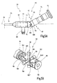
- Fig. 1 to 3 a provided with the general reference numeral 10 endoscope for intubation of an airway is shown.
- the endoscope 10 has an endoscope head 12 at its proximal end and a semi-flexible or rigid endoscope shaft 14 at its distal end.
- the distal end of the endoscope head 12 has a connection 16 for a light guide cable.
- the distal end of the endoscope head 12 is formed with indentations 18-22 so that the doctor can put his fingertips in these indentations 18-22 while he holds the endoscope 10.
- the proximal end of the endoscope head 12 has a focusing ring 24 and an eyecup 26, which are arranged at the outermost proximal end of the endoscope head 12.
- an image guide system 28 extends from the distal end of the endoscope shaft 14 to the eyepiece 30 located at the proximal end of the endoscope head 12.
- a joint 32 is arranged, so that the eyepiece 30 can be bent relative to the longitudinal direction 34 of the shaft 14.
- the longitudinal direction 34 of the shaft 14 indicates the direction defined by the proximal end of the shaft 14.
- the at least two-element joint 32 is designed such that the eyepiece 30 can be bent in a first plane 36 relative to the longitudinal direction 34 of the shaft 14.
- the joint 32 is configured in a second plane 38 transversely to the first plane 36 angled. In Figs. 2B and 2C, these planes 36, 38 correspond to the respective drawing planes.
- the maximum deflection angle is in each case about 50 ° to both sides of the longitudinal direction 34 of the shaft 14.
- the joint 32 is designed as a ball joint 40 with a two-part housing 42 (see FIGS. 1 to 4).
- a housing part 44 is connected to the shaft 14, and a second housing part 46 is connected to the eyepiece 30.
- the first housing part 44 has a spherical outer surface 48, which is accommodated with frictional engagement in a spherical inner surface 50 of the second housing part 46.
- the frictional connection has the advantage that the second housing part is held in the first housing part in a self-locking manner and retains an angled position of the eyepiece 30 relative to the longitudinal direction 34 of the shaft 14, even if the doctor does not hold the second housing part 46.
- the spherical inner surface 50 of the second housing part 46 extends beyond the maximum outer diameter of the spherical outer surface 48 of the first housing part 44.
- This embodiment has the advantage that both housing parts 44, 46 hold each other without further technical effort.
- the first housing part 44 further has a radial constriction 52 on a side facing away from the second housing part 46 side.
- the radial constriction 52 tapers in the longitudinal direction 34 of the shaft 14 seen from the ball joint 40 away.
- the radial Constriction 52 follows the spherical surface of the first housing part 44.
- the radial constriction 52 increases the deflection angle of the second housing part 46 relative to the longitudinal direction 34 of the shaft 14, since the second housing part 46 does not abut against the first housing part 44 over a larger angular range.
- the ball joint 40 permits a deflection of the eyepiece 30 relative to the longitudinal direction 34 of the shaft 14 in all planes which extend through the center of the spherical proximal end of the first housing part 44.
- the maximum deflection angle of the eyepiece 30 relative to the longitudinal direction 34 of the shaft 14 is given by the fact that both housing parts 44, 46 act as a stop together, ie the second housing part 46 abuts the first housing part 44 at a certain deflection angle. In this way, it is prevented that the image guide system 28 is broken in the region of the joint 32.
- the hinge 32 further includes a passageway 54 for passage of a protective tube 56 in which the image guide system 28 is received.
- the passage 54 is configured such that its surface is free of protrusions. As a result, damage to the image guide system 28 is prevented by the inside of the joint 32.
- the protective tube 56 provides additional protection against damage to the image guide system 28 by the joint 32.
- the protective tube 56 is configured such that it fully absorbs the image guidance system 28 and protects the image guidance system 28 equally from damage on all sides by the joint 32.
- FIGS. 5A and 5B an endoscope 60 is shown, wherein the features of the endoscope 60 which are the same as or correspond to those of the endoscope 10 are provided with reference numerals of the endoscope 10 which are increased by 50.
- An eyepiece 80 is angled in a first plane 86 relative to a longitudinal direction 84 of a shaft 64 and in a second plane 88 which is transverse to the first plane 86.
- the bending is made possible by a joint 82 designed as a universal joint 90.
- the universal joint 90 has a two-part housing 92, wherein a first housing part 94 with the shaft 64 and a second housing part 94 is connected to the eyepiece 80. Between the two housing parts 94, 96, a coordinate system 98 is arranged. Both housing parts 94, 96 each have an arcuate element 100, 102, which are arranged transversely to one another and engage in one another. Each arcuate element 100, 102 each has two opposing openings 104-104 'on.
- the axbox 98 has two mutually transverse mounting pins 106, 108 which are interconnected at their respective center. The ends of the fastening pins 106, 108 are received in the openings 104-104 'of the arcuate elements 100, 102.
- the universal joint 90 like the ball joint 40, has a passage 110 through the hinge 82. A protective tube 112 is passed through the passage 110 of the universal joint 90. For the sake of clarity, the protective tube 112 is not shown in FIG. 5B.
- FIGS. 6A and 6B an endoscope 120 is shown, wherein the features of the endoscope 120 which are the same as or correspond to those of the endoscope 10 are provided with reference numerals of the endoscope 10 which are increased by 110.
- An eyepiece 140 is angled in a first plane 146 relative to a longitudinal direction 144 of a shaft 124 and in a second plane 148 which is transverse to the first plane 146.
- the angling is made possible by joint 142 formed as at least two spaced-apart 1-axis joints 150, 152.
- the joint 142 has a three-part housing 154, wherein a first housing part 156 is connected to the shaft 124 and via the 1-axis joint 150 to a second housing part 158.
- the second housing part 158 is connected via the second 1-axis joint 152 with a third housing part 160.
- the third housing part 160 is connected to an eyepiece 140.
- Each 1-axis joint 150, 152 each has a pin 162, 164, which connects the adjoining housing parts 156, 158, 160 articulated.
- the first 1-axis joint 150 is in a plane 146 relative to a longitudinal direction 144 of the shaft 124 and in a second plane 146 transverse to the first Plane 144 can be bent.
- the pins 162, 164 are pierced such that a passage 166 for receiving a light guide system 138 passes through the joint.
- a protective tube 168 is passed through the passage 166 of the joint 142.
- the protective tube 168 is not shown in FIG. 6B.
Landscapes
- Health & Medical Sciences (AREA)
- Life Sciences & Earth Sciences (AREA)
- Pulmonology (AREA)
- General Health & Medical Sciences (AREA)
- Public Health (AREA)
- Veterinary Medicine (AREA)
- Animal Behavior & Ethology (AREA)
- Heart & Thoracic Surgery (AREA)
- Biomedical Technology (AREA)
- Engineering & Computer Science (AREA)
- Otolaryngology (AREA)
- Surgery (AREA)
- Hematology (AREA)
- Anesthesiology (AREA)
- Emergency Medicine (AREA)
- Molecular Biology (AREA)
- Radiology & Medical Imaging (AREA)
- Biophysics (AREA)
- Medical Informatics (AREA)
- Physics & Mathematics (AREA)
- Physiology (AREA)
- Nuclear Medicine, Radiotherapy & Molecular Imaging (AREA)
- Optics & Photonics (AREA)
- Pathology (AREA)
- Endoscopes (AREA)
Applications Claiming Priority (1)
| Application Number | Priority Date | Filing Date | Title |
|---|---|---|---|
| DE102006025621A DE102006025621A1 (de) | 2006-05-24 | 2006-05-24 | Endoskop insbesondere zur Intubation eines Atemwegs |
Publications (2)
| Publication Number | Publication Date |
|---|---|
| EP1859728A2 true EP1859728A2 (fr) | 2007-11-28 |
| EP1859728A3 EP1859728A3 (fr) | 2007-12-05 |
Family
ID=38608825
Family Applications (1)
| Application Number | Title | Priority Date | Filing Date |
|---|---|---|---|
| EP07010219A Withdrawn EP1859728A3 (fr) | 2006-05-24 | 2007-05-23 | Endoscope, en particulier destiné à l'intubation d'une voie respiratoire |
Country Status (3)
| Country | Link |
|---|---|
| US (1) | US20070276186A1 (fr) |
| EP (1) | EP1859728A3 (fr) |
| DE (1) | DE102006025621A1 (fr) |
Cited By (1)
| Publication number | Priority date | Publication date | Assignee | Title |
|---|---|---|---|---|
| EP2253265A1 (fr) | 2009-05-20 | 2010-11-24 | Karl Storz GmbH & Co. KG | Endoscope |
Families Citing this family (2)
| Publication number | Priority date | Publication date | Assignee | Title |
|---|---|---|---|---|
| CN101732082B (zh) * | 2009-11-06 | 2011-06-22 | 广州宝胆医疗器械科技有限公司 | 软、硬子母胆囊、胆管镜系统 |
| USD754336S1 (en) * | 2014-09-02 | 2016-04-19 | Karl Storz Gmbh & Co. Kg | Bronchoscope |
Citations (1)
| Publication number | Priority date | Publication date | Assignee | Title |
|---|---|---|---|---|
| DE10351185A1 (de) | 2003-11-03 | 2005-06-09 | Olympus Winter & Ibe Gmbh | Endoskopoptik mit Biegeabschnitt |
Family Cites Families (10)
| Publication number | Priority date | Publication date | Assignee | Title |
|---|---|---|---|---|
| ATE29206T1 (de) * | 1983-01-25 | 1987-09-15 | Storz Endoskop Gmbh | Instrument zur einfuehrung von narkosekathetern. |
| GB8615884D0 (en) * | 1986-06-30 | 1986-08-06 | Yentis S M | Laryngoscopes |
| US5377668A (en) * | 1993-04-12 | 1995-01-03 | Optimed Technologies, Inc. | Apparatus and method for endoscopic diagnostics and therapy |
| US5695454A (en) * | 1994-06-30 | 1997-12-09 | Mourkidou; Sotiria | Cover for a laryngoscope |
| IT1278856B1 (it) * | 1995-09-19 | 1997-11-28 | Orthofix Srl | Accessorio per fissatore esterno |
| US5704899A (en) * | 1995-10-10 | 1998-01-06 | Conceptus, Inc. | Protective sheath for a fiberoptic image guide within an articulated endoscope |
| US6309388B1 (en) * | 1999-12-23 | 2001-10-30 | Mayo Foundation For Medical Education And Research | Symmetric conization electrocautery device |
| EP1406545B1 (fr) * | 2001-06-14 | 2015-10-28 | Endoevolution, Llc | Appareil et procede de suture chirurgicale avec gestion de fil |
| US7182728B2 (en) * | 2002-07-24 | 2007-02-27 | Intubation Plus, Inc. | Laryngoscope with multi-directional eyepiece |
| US20050090712A1 (en) * | 2003-10-23 | 2005-04-28 | Anthony Cubb | Res-Q-Scope |
-
2006
- 2006-05-24 DE DE102006025621A patent/DE102006025621A1/de not_active Withdrawn
-
2007
- 2007-05-23 EP EP07010219A patent/EP1859728A3/fr not_active Withdrawn
- 2007-05-23 US US11/752,486 patent/US20070276186A1/en not_active Abandoned
Patent Citations (1)
| Publication number | Priority date | Publication date | Assignee | Title |
|---|---|---|---|---|
| DE10351185A1 (de) | 2003-11-03 | 2005-06-09 | Olympus Winter & Ibe Gmbh | Endoskopoptik mit Biegeabschnitt |
Cited By (2)
| Publication number | Priority date | Publication date | Assignee | Title |
|---|---|---|---|---|
| EP2253265A1 (fr) | 2009-05-20 | 2010-11-24 | Karl Storz GmbH & Co. KG | Endoscope |
| DE102009022118A1 (de) | 2009-05-20 | 2010-11-25 | Karl Storz Gmbh & Co. Kg | Endoskop |
Also Published As
| Publication number | Publication date |
|---|---|
| EP1859728A3 (fr) | 2007-12-05 |
| US20070276186A1 (en) | 2007-11-29 |
| DE102006025621A1 (de) | 2007-11-29 |
Similar Documents
| Publication | Publication Date | Title |
|---|---|---|
| EP1202767B1 (fr) | Dispositif endoscopique destine notamment a une installation d'urgence | |
| EP1224904B1 (fr) | endoscope pour l'intubation en urgence | |
| EP1150734B1 (fr) | Dispositif d'introduction d'un tube d'intubation dans la trachee | |
| DE4039746C2 (de) | Starres, faseroptisches Intubations-Laryngoskop | |
| DE19906191A1 (de) | Endoskop | |
| DE102018110620A1 (de) | Endoskopdeflecting mit distalem Abklappmechanismus | |
| DE102007013749A1 (de) | Einführteil für ein Endoskop | |
| WO2001056460A1 (fr) | Dispositif permettant de traiter un patient de maniere intracorporelle et a invasion minimale | |
| DE102017107978B4 (de) | Endoskopkopf mit schwenkbarer Kamera- und Arbeitskanal-Einheit | |
| EP3897345A1 (fr) | Endoscope comprenant un canal de travail extensible | |
| EP3266366B1 (fr) | Laryngoscope adaptatif et spatule adaptative pour un laryngoscope | |
| EP3917373A1 (fr) | Endoscope comprenant un mécanisme pivotant distal et un ajustement fin | |
| EP1859728A2 (fr) | Endoscope, en particulier destiné à l'intubation d'une voie respiratoire | |
| EP2253265B1 (fr) | Endoscope | |
| DE3916288A1 (de) | Uretero-renoskop sowie endoskop | |
| WO2010105649A1 (fr) | Queue tubulaire d'un instrument chirurgical et son utilisation | |
| EP0120112B1 (fr) | Instrument pour l'introduction de cathéters de narcose | |
| DE102004015291B4 (de) | Aufsetzkappe für Endoskop-Einführungsschläuche sowie Endoskopeinheit | |
| WO2010009720A1 (fr) | Endoscope commandable | |
| EP3727540B1 (fr) | Canule trachéale et procédé pour sa production | |
| EP0742026A1 (fr) | Endoscope, utilisé en particulier pour l'intubation trachéale | |
| DE102020118047A1 (de) | Ablenksteuerungsmechanismus für ein lenkbares flexibles Endoskop, lenkbares flexibles Endoskop, Endoskopmontagesatz und Verfahren zur Montage eines flexiblen Endoskops | |
| DE2850613C2 (de) | Laryngoskop | |
| DE10351185A1 (de) | Endoskopoptik mit Biegeabschnitt | |
| DE202015003133U1 (de) | Schutzabdeckung für ein chirurgisches Instrument |
Legal Events
| Date | Code | Title | Description |
|---|---|---|---|
| PUAI | Public reference made under article 153(3) epc to a published international application that has entered the european phase |
Free format text: ORIGINAL CODE: 0009012 |
|
| PUAL | Search report despatched |
Free format text: ORIGINAL CODE: 0009013 |
|
| AK | Designated contracting states |
Kind code of ref document: A2 Designated state(s): AT BE BG CH CY CZ DE DK EE ES FI FR GB GR HU IE IS IT LI LT LU LV MC MT NL PL PT RO SE SI SK TR |
|
| AX | Request for extension of the european patent |
Extension state: AL BA HR MK YU |
|
| AK | Designated contracting states |
Kind code of ref document: A3 Designated state(s): AT BE BG CH CY CZ DE DK EE ES FI FR GB GR HU IE IS IT LI LT LU LV MC MT NL PL PT RO SE SI SK TR |
|
| AX | Request for extension of the european patent |
Extension state: AL BA HR MK YU |
|
| 17P | Request for examination filed |
Effective date: 20080604 |
|
| 17Q | First examination report despatched |
Effective date: 20080708 |
|
| AKX | Designation fees paid |
Designated state(s): DE FR GB IT |
|
| STAA | Information on the status of an ep patent application or granted ep patent |
Free format text: STATUS: THE APPLICATION IS DEEMED TO BE WITHDRAWN |
|
| 18D | Application deemed to be withdrawn |
Effective date: 20090319 |