EP1859728A2 - Endoscope, in particular for intubation of an airway - Google Patents
Endoscope, in particular for intubation of an airway Download PDFInfo
- Publication number
- EP1859728A2 EP1859728A2 EP07010219A EP07010219A EP1859728A2 EP 1859728 A2 EP1859728 A2 EP 1859728A2 EP 07010219 A EP07010219 A EP 07010219A EP 07010219 A EP07010219 A EP 07010219A EP 1859728 A2 EP1859728 A2 EP 1859728A2
- Authority
- EP
- European Patent Office
- Prior art keywords
- joint
- eyepiece
- housing part
- shaft
- endoscope according
- Prior art date
- Legal status (The legal status is an assumption and is not a legal conclusion. Google has not performed a legal analysis and makes no representation as to the accuracy of the status listed.)
- Withdrawn
Links
Images


Classifications
-
- A—HUMAN NECESSITIES
- A61—MEDICAL OR VETERINARY SCIENCE; HYGIENE
- A61B—DIAGNOSIS; SURGERY; IDENTIFICATION
- A61B1/00—Instruments for performing medical examinations of the interior of cavities or tubes of the body by visual or photographical inspection, e.g. endoscopes; Illuminating arrangements therefor
- A61B1/267—Instruments for performing medical examinations of the interior of cavities or tubes of the body by visual or photographical inspection, e.g. endoscopes; Illuminating arrangements therefor for the respiratory tract, e.g. laryngoscopes, bronchoscopes
-
- A—HUMAN NECESSITIES
- A61—MEDICAL OR VETERINARY SCIENCE; HYGIENE
- A61M—DEVICES FOR INTRODUCING MEDIA INTO, OR ONTO, THE BODY; DEVICES FOR TRANSDUCING BODY MEDIA OR FOR TAKING MEDIA FROM THE BODY; DEVICES FOR PRODUCING OR ENDING SLEEP OR STUPOR
- A61M16/00—Devices for influencing the respiratory system of patients by gas treatment, e.g. mouth-to-mouth respiration; Tracheal tubes
- A61M16/04—Tracheal tubes
- A61M16/0488—Mouthpieces; Means for guiding, securing or introducing the tubes
-
- A—HUMAN NECESSITIES
- A61—MEDICAL OR VETERINARY SCIENCE; HYGIENE
- A61M—DEVICES FOR INTRODUCING MEDIA INTO, OR ONTO, THE BODY; DEVICES FOR TRANSDUCING BODY MEDIA OR FOR TAKING MEDIA FROM THE BODY; DEVICES FOR PRODUCING OR ENDING SLEEP OR STUPOR
- A61M16/00—Devices for influencing the respiratory system of patients by gas treatment, e.g. mouth-to-mouth respiration; Tracheal tubes
- A61M16/08—Bellows; Connecting tubes ; Water traps; Patient circuits
- A61M16/0816—Joints or connectors
- A61M16/0825—Joints or connectors with ball-sockets
Definitions
- the invention relates to an endoscope, in particular for the intubation of a respiratory tract, with a shaft and an eyepiece at the proximal end of an endoscope head, and with a joint between the shaft and the eyepiece for angling the eyepiece relative to a longitudinal direction of the shaft, wherein the joint is formed is that the eyepiece is angled in a first plane.
- Such an instrument is for example from the DE company brochure of Karl Storz GmbH & Co. KG, Tuttlingen, "Karl Storz Endoscopes, Endoscopes for Anesthesia and Emergency Medicine", 3rd edition 1/2004, page AN-SET 9 B , known. From this brochure, an endoscope provided with the instrument number 10330 B is known.
- the known endoscope is used to intubate the airway of a human, with the distal end of the endoscope being inserted through the nose or mouth of a patient into the trachea for optically controlling the insertion of an intubation tube.
- the endoscope has an endoscope shaft and an endoscope head, wherein an eyepiece is arranged at the proximal end of the endoscope head. The eyepiece and the shaft are connected by a joint.
- a joint in the sense of the present invention has at least two elements which interact with one another by rotation and / or translation.
- the endoscope head of the known endoscope has a two-part housing, wherein the joint between two housing parts is arranged and the proximal end of the shaft extends in the same longitudinal direction as the distal end of the endoscope head.
- the longitudinal direction of the endoscope shaft designates that direction which is defined by the longitudinal direction of the proximal shaft end.
- the eyepiece is angled out of a zero degree position, which may for example coincide with the longitudinal direction of the shaft.
- Illumination light is coupled at the distal end of the endoscope head distal of the joint via a connector in a light guide system, which extends to the distal end of the shaft.
- Observation light of the imaging system is passed from the distal end of the shaft via an image guidance system through the joint to the eyepiece.
- the image guidance system has ordered optical fibers and / or a lens system for guiding light and focusing.
- the image guidance system can be designed as a semi-flexible or flexible light guide.
- Such endoscopes are preferably used in emergency medicine.
- a physician who is in a stooped posture over a patient, holds the endoscope to his endoscope head with the distal end of the shaft inserted into the trachea of the patient.
- a hand of the doctor at the proximal end of the endoscope head and the other hand at the distal end of the endoscope head to be able to angle the eyepiece relative to the longitudinal direction of the shaft.
- the angled eyepiece allows the physician to assume such a position with the patient that during the procedure he need not be directly above the patient's nose and mouth openings.
- the eyepiece of the known from the prior art endoscope is bendable only in a defined plane relative to the longitudinal direction of the shaft, so that the freedom of movement of the doctor is limited.
- the position of the physician to the patient is such that the physician is at least partially above the patient, the physician must remain in a physically demanding and cumbersome posture throughout the procedure.
- the endoscope must either be reinserted into the trachea or the patient must be turned into a favorable position. There is a risk here that additional injuries will be inflicted on the patient.
- a rotation of the endoscope about the longitudinal direction of the shaft is not possible in a semi-flexible shaft or even rigid shaft with a curved course when the endoscope is inserted into the trachea.
- an endoscope with a bending flexible bending section known, wherein the endoscope between the distal end of the shaft and the proximal end of the endoscope head has a working channel for performing a light guide system and instrument channels.
- the eyepiece which sits at the proximal end of the endoscope head, can be bent over the bending section from its straight position.
- the bending portion is formed as a one-piece tube with a spiral reinforcement along its longitudinal extent between a fixed end piece at the proximal end of the endoscope head and a housing of the endoscope head.
- a bending section has the disadvantage over a joint that it can become tired after many bending changes, ie that it can become slack after prolonged use of the endoscope.
- the bending portion may have uneven, serpentine bent areas, because no fixed bending point is defined.
- Such bent Regions of the bending section through which the image guidance system passes for the observation lead to a corresponding serpentine course of the light guidance system, which can impair the imaging quality of the image guidance system.
- the invention has for its object to provide an endoscope of the type mentioned that allows the doctor greater freedom of movement during observation by the endoscope.
- this object is achieved in terms of the aforementioned endoscope in that the joint which is arranged between the shaft and the eyepiece, is formed so that the eyepiece is at least in a second plane, which is transverse to the first plane, angled.
- the endoscope according to the invention not only allows the bending of the eyepiece in a defined plane relative to the longitudinal direction of the shaft. Rather, the eyepiece is spatially formed relative to the longitudinal direction of the shaft angled.
- the endoscope according to the invention advantageously provides the physician with an increased freedom of movement during the procedure, since the relative alignability of the eyepiece with the shaft is increased by at least a second angle range which is given by a second plane transverse to the first plane.
- the doctor can work fatigue-free, since he can remain in a physically relaxed posture during the procedure.
- Another advantage of the endoscope according to the invention lies in its ease of handling during the procedure, so that even doctors without many years of professional experience in dealing with endoscopes can use the endoscope of the present invention. Due to the spatial bendability of the endoscope, care must be taken during the introduction of the endoscope, not how the angled eyepiece is arranged to the longitudinal direction of the shaft in order to allow the doctor a favorable position to the patient. The doctor can still after insertion of the endoscope to take the most appropriate position for him to the patient by angling the eyepiece in the desired direction.
- the present endoscope which can be used in particular in the field of emergency medicine, allows a time-saving application during the procedure. If the endoscope is already inserted into the trachea of the patient and the position of the patient to the doctor for further treatment is not suitable, without re-introducing the endoscope into the trachea, the eyepiece can be angled relative to the shaft in the most favorable spatial position.
- the joint of the endoscope is formed so that the eyepiece at least in one of the first or second plane up to an angle of about 50 °, preferably up to an angle of about 40 ° and more preferably up to an angle is bendable from about 30 ° relative to the longitudinal direction of the shaft.
- This measure has the advantage that the maximum angular range of one of the two planes, which is given by the angling of the eyepiece on both sides relative to the longitudinal direction of the shaft, is 100 °, 80 ° or 60 ° and gives the physician a great deal of freedom of movement.
- the joint is designed as a ball joint.
- the joint can be made structurally simple and inexpensive.
- the ball joint allows a user-friendly handling of the endoscope, since the desired Abwinkel ein of the eyepiece relative to the longitudinal direction of the shaft is reached directly. The doctor does not have to consider during intubation, in which angular steps the eyepiece must be angled.
- the ball joint on a two-part housing, wherein a first housing part is connected to the shaft and a second housing part with the eyepiece.
- This measure has the advantage that the housing provides a stable compact protection for the light guide system.
- the endoscope head for the doctor is handy and well-formed in a structurally simple manner. Due to the division of the housing at the same time the function of the spatial deflection is realized relative to the longitudinal direction of the shaft.
- the first housing part is accommodated with frictional engagement in the second housing part in a sliding manner.
- the first housing part has a spherical outer surface and the second housing part has a spherical inner surface, in which the first housing part is accommodated.
- both housing parts are smooth and without projections and so the movement of both housing parts is not limited to one another. Since both the outer surface of the first housing part and the inner surface of the second housing part are spherical, both housing parts are accurately connected to each other. In addition, the spherical configuration of the two housing parts allows the bending of the eyepiece relative to the longitudinal direction of the shaft in more than one second plane transversely to the first plane. This allows the eyepiece to be moved on a spherical shell.
- the first housing part is arranged in the second housing part such that the second housing part extends beyond the maximum outer diameter of the spherical outer surface of the first housing part.
- This measure has the advantage that both housing parts are fastened to each other without further technical measures.
- the spherical outer surface of the first housing part has a radial constriction on a side facing away from the second housing part.
- This measure has the advantage that the radial constriction widens the range of motion of the second housing part relative to the first housing part, since the second housing part can be moved further beyond the outer surface of the first housing part and does not abut it.
- the radial constriction tapers in the longitudinal direction seen from the joint.
- This measure has the advantage that the constriction, which becomes smaller radially in the longitudinal direction of the shank, increases the maximum range of movement of the second housing part relative to the first housing part.
- both housing parts act together as a stop for limiting the bending of the eyepiece.
- This measure has the advantage that the maximum deflection angle of the eyepiece is limited relative to the longitudinal direction of the shaft and the guided through the joint image guide system can not be broken by excessive bending.
- the joint is designed as a universal joint.
- the joint can be made technically simple and inexpensive to create a spatial angulation of the eyepiece.
- the universal joint has a two-part housing and an axle cross, with a first housing part being connected to the shaft and a second housing part being connected to the eyepiece, and the axbox being arranged between the two housing parts.
- the housing offers a compact and stable protection for the image guidance system.
- the joint housing allows the doctor during the procedure good handling of the endoscope.
- the axbox between the two housing parts allows the bending of the eyepiece relative to the shaft in at least two mutually transverse planes.
- the joint has at least two mutually spaced 1-axis joints.
- This measure represents a further technically simple and cost-effective embodiment of the joint, in order to allow a spatial bending of the eyepiece relative to the longitudinal direction of the shaft.
- the joint has a passage for the passage of the image guide system, wherein the passage is free of projections.
- This measure has the advantage that the image guidance system is protected against damage by the inside of the joint when the eyepiece is being bent.
- the joint has a protective tube for the image guidance system, wherein the protective tube extends through the passage of the joint and receives the image guidance system.
- This measure has the advantage that the sensitive image guide system is even better protected by the protective tube from damage.
- the protective tube extends completely around the image guidance system.
- This measure has the advantage that the image guidance system is equally equally protected against damage on all sides.
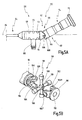
- Fig. 1 to 3 a provided with the general reference numeral 10 endoscope for intubation of an airway is shown.
- the endoscope 10 has an endoscope head 12 at its proximal end and a semi-flexible or rigid endoscope shaft 14 at its distal end.
- the distal end of the endoscope head 12 has a connection 16 for a light guide cable.
- the distal end of the endoscope head 12 is formed with indentations 18-22 so that the doctor can put his fingertips in these indentations 18-22 while he holds the endoscope 10.
- the proximal end of the endoscope head 12 has a focusing ring 24 and an eyecup 26, which are arranged at the outermost proximal end of the endoscope head 12.
- an image guide system 28 extends from the distal end of the endoscope shaft 14 to the eyepiece 30 located at the proximal end of the endoscope head 12.
- a joint 32 is arranged, so that the eyepiece 30 can be bent relative to the longitudinal direction 34 of the shaft 14.
- the longitudinal direction 34 of the shaft 14 indicates the direction defined by the proximal end of the shaft 14.
- the at least two-element joint 32 is designed such that the eyepiece 30 can be bent in a first plane 36 relative to the longitudinal direction 34 of the shaft 14.
- the joint 32 is configured in a second plane 38 transversely to the first plane 36 angled. In Figs. 2B and 2C, these planes 36, 38 correspond to the respective drawing planes.
- the maximum deflection angle is in each case about 50 ° to both sides of the longitudinal direction 34 of the shaft 14.
- the joint 32 is designed as a ball joint 40 with a two-part housing 42 (see FIGS. 1 to 4).
- a housing part 44 is connected to the shaft 14, and a second housing part 46 is connected to the eyepiece 30.
- the first housing part 44 has a spherical outer surface 48, which is accommodated with frictional engagement in a spherical inner surface 50 of the second housing part 46.
- the frictional connection has the advantage that the second housing part is held in the first housing part in a self-locking manner and retains an angled position of the eyepiece 30 relative to the longitudinal direction 34 of the shaft 14, even if the doctor does not hold the second housing part 46.
- the spherical inner surface 50 of the second housing part 46 extends beyond the maximum outer diameter of the spherical outer surface 48 of the first housing part 44.
- This embodiment has the advantage that both housing parts 44, 46 hold each other without further technical effort.
- the first housing part 44 further has a radial constriction 52 on a side facing away from the second housing part 46 side.
- the radial constriction 52 tapers in the longitudinal direction 34 of the shaft 14 seen from the ball joint 40 away.
- the radial Constriction 52 follows the spherical surface of the first housing part 44.
- the radial constriction 52 increases the deflection angle of the second housing part 46 relative to the longitudinal direction 34 of the shaft 14, since the second housing part 46 does not abut against the first housing part 44 over a larger angular range.
- the ball joint 40 permits a deflection of the eyepiece 30 relative to the longitudinal direction 34 of the shaft 14 in all planes which extend through the center of the spherical proximal end of the first housing part 44.
- the maximum deflection angle of the eyepiece 30 relative to the longitudinal direction 34 of the shaft 14 is given by the fact that both housing parts 44, 46 act as a stop together, ie the second housing part 46 abuts the first housing part 44 at a certain deflection angle. In this way, it is prevented that the image guide system 28 is broken in the region of the joint 32.
- the hinge 32 further includes a passageway 54 for passage of a protective tube 56 in which the image guide system 28 is received.
- the passage 54 is configured such that its surface is free of protrusions. As a result, damage to the image guide system 28 is prevented by the inside of the joint 32.
- the protective tube 56 provides additional protection against damage to the image guide system 28 by the joint 32.
- the protective tube 56 is configured such that it fully absorbs the image guidance system 28 and protects the image guidance system 28 equally from damage on all sides by the joint 32.
- FIGS. 5A and 5B an endoscope 60 is shown, wherein the features of the endoscope 60 which are the same as or correspond to those of the endoscope 10 are provided with reference numerals of the endoscope 10 which are increased by 50.
- An eyepiece 80 is angled in a first plane 86 relative to a longitudinal direction 84 of a shaft 64 and in a second plane 88 which is transverse to the first plane 86.
- the bending is made possible by a joint 82 designed as a universal joint 90.
- the universal joint 90 has a two-part housing 92, wherein a first housing part 94 with the shaft 64 and a second housing part 94 is connected to the eyepiece 80. Between the two housing parts 94, 96, a coordinate system 98 is arranged. Both housing parts 94, 96 each have an arcuate element 100, 102, which are arranged transversely to one another and engage in one another. Each arcuate element 100, 102 each has two opposing openings 104-104 'on.
- the axbox 98 has two mutually transverse mounting pins 106, 108 which are interconnected at their respective center. The ends of the fastening pins 106, 108 are received in the openings 104-104 'of the arcuate elements 100, 102.
- the universal joint 90 like the ball joint 40, has a passage 110 through the hinge 82. A protective tube 112 is passed through the passage 110 of the universal joint 90. For the sake of clarity, the protective tube 112 is not shown in FIG. 5B.
- FIGS. 6A and 6B an endoscope 120 is shown, wherein the features of the endoscope 120 which are the same as or correspond to those of the endoscope 10 are provided with reference numerals of the endoscope 10 which are increased by 110.
- An eyepiece 140 is angled in a first plane 146 relative to a longitudinal direction 144 of a shaft 124 and in a second plane 148 which is transverse to the first plane 146.
- the angling is made possible by joint 142 formed as at least two spaced-apart 1-axis joints 150, 152.
- the joint 142 has a three-part housing 154, wherein a first housing part 156 is connected to the shaft 124 and via the 1-axis joint 150 to a second housing part 158.
- the second housing part 158 is connected via the second 1-axis joint 152 with a third housing part 160.
- the third housing part 160 is connected to an eyepiece 140.
- Each 1-axis joint 150, 152 each has a pin 162, 164, which connects the adjoining housing parts 156, 158, 160 articulated.
- the first 1-axis joint 150 is in a plane 146 relative to a longitudinal direction 144 of the shaft 124 and in a second plane 146 transverse to the first Plane 144 can be bent.
- the pins 162, 164 are pierced such that a passage 166 for receiving a light guide system 138 passes through the joint.
- a protective tube 168 is passed through the passage 166 of the joint 142.
- the protective tube 168 is not shown in FIG. 6B.
Abstract
Description
Die Erfindung betrifft ein Endoskop, insbesondere zur Intubation eines Atemwegs, mit einem Schaft und einem Okular am proximalen Ende eines Endoskopkopfes, und mit einem Gelenk zwischen dem Schaft und dem Okular zum Abwinkeln des Okulars relativ zu einer Längsrichtung des Schafts, wobei das Gelenk so ausgebildet ist, dass das Okular in einer ersten Ebene abwinkelbar ist.The invention relates to an endoscope, in particular for the intubation of a respiratory tract, with a shaft and an eyepiece at the proximal end of an endoscope head, and with a joint between the shaft and the eyepiece for angling the eyepiece relative to a longitudinal direction of the shaft, wherein the joint is formed is that the eyepiece is angled in a first plane.
Ein derartiges Instrument ist beispielsweise aus dem DE-Firmenprospekt der
Das bekannte Endoskop wird zur Intubation der Atemwege eines Menschen verwendet, wobei das distale Ende des Endoskops durch die Nase oder den Mund eines Patienten in die Luftröhre zur optischen Kontrolle der Einführung eines Intubationsschlauchs eingeführt wird. Das Endoskop weist einen Endoskopschaft und einen Endoskopkopf auf, wobei ein Okular am proximalen Ende des Endoskopkopfs angeordnet ist. Das Okular und der Schaft sind über ein Gelenk miteinander verbunden.The known endoscope is used to intubate the airway of a human, with the distal end of the endoscope being inserted through the nose or mouth of a patient into the trachea for optically controlling the insertion of an intubation tube. The endoscope has an endoscope shaft and an endoscope head, wherein an eyepiece is arranged at the proximal end of the endoscope head. The eyepiece and the shaft are connected by a joint.
Ein Gelenk im Sinne der vorliegenden Erfindung weist zumindest zwei Elemente auf, die durch Rotation und/oder Translation aufeinander wirken.A joint in the sense of the present invention has at least two elements which interact with one another by rotation and / or translation.
Der Endoskopkopf des bekannten Endoskops weist ein zweiteiliges Gehäuse auf, wobei das Gelenk zwischen beiden Gehäuseteilen angeordnet ist und das proximale Ende des Schafts in gleicher Längsrichtung wie das distale Ende des Endoskopkopfs verläuft. Die Längsrichtung des Endoskopschafts bezeichnet im Folgenden diejenige Richtung, die durch die Längsrichtung des proximalen Schaftendes definiert ist. Das Okular ist aus einer Nullgradstellung heraus abwinkelbar, die beispielsweise mit der Längsrichtung des Schafts übereinstimmen kann.The endoscope head of the known endoscope has a two-part housing, wherein the joint between two housing parts is arranged and the proximal end of the shaft extends in the same longitudinal direction as the distal end of the endoscope head. In the following, the longitudinal direction of the endoscope shaft designates that direction which is defined by the longitudinal direction of the proximal shaft end. The eyepiece is angled out of a zero degree position, which may for example coincide with the longitudinal direction of the shaft.
Beleuchtungslicht wird am distalen Ende des Endoskopkopfes distalseitig des Gelenks über einen Anschluss in ein Lichtleitsystem eingekoppelt, das sich bis zum distalen Ende des Schafts erstreckt. Beobachtungslicht des bildgebenden Systems wird vom distalen Ende des Schafts über ein Bildleitsystem durch das Gelenk hindurch zum Okular geleitet. Das Bildleitsystem weist geordnete Lichtleitfasern und/oder ein Linsensystem zur Lichtleitung und Fokussierung auf. Das Bildleitsystem kann als semi-flexibler oder flexibler Lichtleiter ausgebildet sein.Illumination light is coupled at the distal end of the endoscope head distal of the joint via a connector in a light guide system, which extends to the distal end of the shaft. Observation light of the imaging system is passed from the distal end of the shaft via an image guidance system through the joint to the eyepiece. The image guidance system has ordered optical fibers and / or a lens system for guiding light and focusing. The image guidance system can be designed as a semi-flexible or flexible light guide.
Solche Endoskope kommen bevorzugt in der Notfallmedizin zum Einsatz. Ein Arzt, der sich in gebeugter Körperhaltung über einem Patienten befindet, hält das Endoskop an seinem Endoskopkopf, wobei das distale Ende des Schafts in die Luftröhre des Patienten eingeführt wird. Hierbei befindet sich eine Hand des Arztes am proximalen Ende des Endoskopkopfes und die andere Hand am distalen Ende des Endoskopkopfes, um das Okular relativ zur Längsrichtung des Schafts abwinkeln zu können. Das abwinkelbar ausgebildete Okular ermöglicht es dem Arzt, eine solche Position zum Patienten einzunehmen, dass er sich während des Eingriffs nicht direkt über den Nasen- und Mundöffnungen des Patienten befinden muss.Such endoscopes are preferably used in emergency medicine. A physician, who is in a stooped posture over a patient, holds the endoscope to his endoscope head with the distal end of the shaft inserted into the trachea of the patient. Here is a hand of the doctor at the proximal end of the endoscope head and the other hand at the distal end of the endoscope head, to be able to angle the eyepiece relative to the longitudinal direction of the shaft. The angled eyepiece allows the physician to assume such a position with the patient that during the procedure he need not be directly above the patient's nose and mouth openings.
Allerdings ist das Okular des aus dem Stand der Technik bekannten Endoskops nur in einer definierten Ebene relativ zur Längsrichtung des Schafts abwinkelbar, so dass die Bewegungsfreiheit des Arztes eingeschränkt ist. In einer Situation, in der die Stellung des Arztes zum Patienten derart ist, dass sich der Arzt zumindest teilweise über dem Patient befindet, muss der Arzt in körperlich anstrengender und für ihn umständlicher Haltung während des gesamten Eingriffs verbleiben. Falls für den Arzt keine akzeptable Ausrichtung des Okulars zum Schaft gefunden werden kann, muss das Endoskop entweder erneut in die Luftröhre eingeführt werden oder der Patient in eine günstige Position gedreht werden. Hierbei besteht die Gefahr, dass dem Patienten zusätzlich Verletzungen zugefügt werden. Eine Drehung des Endoskops um die Längsrichtung des Schafts ist bei einem semi-flexiblen Schaft oder gar starren Schaft mit gekrümmten Verlauf nicht möglich, wenn das Endoskop in die Luftröhre eingeführt ist.However, the eyepiece of the known from the prior art endoscope is bendable only in a defined plane relative to the longitudinal direction of the shaft, so that the freedom of movement of the doctor is limited. In a situation where the position of the physician to the patient is such that the physician is at least partially above the patient, the physician must remain in a physically demanding and cumbersome posture throughout the procedure. If the doctor can not find an acceptable alignment of the eyepiece with the shaft, the endoscope must either be reinserted into the trachea or the patient must be turned into a favorable position. There is a risk here that additional injuries will be inflicted on the patient. A rotation of the endoscope about the longitudinal direction of the shaft is not possible in a semi-flexible shaft or even rigid shaft with a curved course when the endoscope is inserted into the trachea.
Ferner ist aus
Der Erfindung liegt die Aufgabe zugrunde, ein Endoskop der eingangs genannten Art zu schaffen, das dem Arzt eine größere Bewegungsfreiheit bei der Beobachtung durch das Endoskop erlaubt.The invention has for its object to provide an endoscope of the type mentioned that allows the doctor greater freedom of movement during observation by the endoscope.
Erfindungsgemäß wird diese Aufgabe hinsichtlich des eingangs genannten Endoskops dadurch gelöst, dass das Gelenk, das zwischen dem Schaft und dem Okular angeordnet ist, so ausgebildet ist, dass das Okular zumindest in einer zweiten Ebene, die quer zur ersten Ebene verläuft, abwinkelbar ist.According to the invention this object is achieved in terms of the aforementioned endoscope in that the joint which is arranged between the shaft and the eyepiece, is formed so that the eyepiece is at least in a second plane, which is transverse to the first plane, angled.
Demnach erlaubt das erfindungsgemäße Endoskop nicht nur die Abwinklung des Okulars in einer definierten Ebene relativ zur Längsrichtung des Schafts. Vielmehr ist das Okular räumlich relativ zur Längsrichtung des Schafts abwinkelbar ausgebildet. Das erfindungsgemäße Endoskop bietet vorteilhafterweise dem Arzt eine erweiterte Bewegungsfreiheit während des Eingriffs, da die relative Ausrichtbarkeit des Okulars zum Schaft um zumindest einen zweiten Winkelbereich, der durch eine zweite Ebene quer zur ersten Ebene gegeben ist, vergrößert ist. Zudem kann der Arzt ermüdungsfrei arbeiten, da er in einer körperlich entspannten Haltung während des Eingriffs verbleiben kann.Accordingly, the endoscope according to the invention not only allows the bending of the eyepiece in a defined plane relative to the longitudinal direction of the shaft. Rather, the eyepiece is spatially formed relative to the longitudinal direction of the shaft angled. The endoscope according to the invention advantageously provides the physician with an increased freedom of movement during the procedure, since the relative alignability of the eyepiece with the shaft is increased by at least a second angle range which is given by a second plane transverse to the first plane. In addition, the doctor can work fatigue-free, since he can remain in a physically relaxed posture during the procedure.
Ein weiterer Vorteil des erfindungsgemäßen Endoskops liegt in seiner einfachen Handhabbarkeit während des Eingriffs, so dass auch Ärzte ohne langjährige Berufserfahrung im Umgang mit Endoskopen das Endoskop der vorliegenden Erfindung verwenden können. Aufgrund der räumlichen Abwinkelbarkeit des Endoskops muss während der Einführung des Endoskops nicht darauf geachtet werden, wie das abgewinkelte Okular zur Längsrichtung des Schafts angeordnet ist, um dem Arzt eine günstige Stellung zum Patienten zu ermöglichen. Der Arzt kann noch nach Einführen des Endoskops die für ihn geeignetste Stellung zum Patienten einnehmen, indem er das Okular in die gewünschte Richtung abwinkelt.Another advantage of the endoscope according to the invention lies in its ease of handling during the procedure, so that even doctors without many years of professional experience in dealing with endoscopes can use the endoscope of the present invention. Due to the spatial bendability of the endoscope, care must be taken during the introduction of the endoscope, not how the angled eyepiece is arranged to the longitudinal direction of the shaft in order to allow the doctor a favorable position to the patient. The doctor can still after insertion of the endoscope to take the most appropriate position for him to the patient by angling the eyepiece in the desired direction.
Darüber hinaus ermöglicht das vorliegende Endoskop, das insbesondere im Bereich der Notfallmedizin eingesetzt werden kann, eine zeitsparende Anwendung während des Eingriffs. Ist das Endoskop bereits in die Luftröhre des Patienten eingeführt und die Stellung des Patienten zum Arzt für die weitere Behandlung nicht geeignet, kann, ohne das Endoskop erneut in die Luftröhre einzuführen, das Okular relativ zum Schaft in die günstigste räumliche Lage abgewinkelt werden.In addition, the present endoscope, which can be used in particular in the field of emergency medicine, allows a time-saving application during the procedure. If the endoscope is already inserted into the trachea of the patient and the position of the patient to the doctor for further treatment is not suitable, without re-introducing the endoscope into the trachea, the eyepiece can be angled relative to the shaft in the most favorable spatial position.
In einer bevorzugten Ausgestaltung der Erfindung ist das Gelenk des Endoskops so ausgebildet, dass das Okular zumindest in einer der ersten oder zweiten Ebene bis zu einem Winkel von etwa 50°, vorzugsweise bis zu einem Winkel von etwa 40° und weiter vorzugsweise bis zu einem Winkel von etwa 30° relativ zur Längsrichtung des Schafts abwinkelbar ist.In a preferred embodiment of the invention, the joint of the endoscope is formed so that the eyepiece at least in one of the first or second plane up to an angle of about 50 °, preferably up to an angle of about 40 ° and more preferably up to an angle is bendable from about 30 ° relative to the longitudinal direction of the shaft.
Diese Maßnahme hat den Vorteil, dass der maximale Winkelbereich einer der beiden Ebenen, der durch die Abwinkelung des Okulars zu beiden Seiten relativ zur Längsrichtung des Schafts gegeben ist, 100°, 80° beziehungsweise 60° beträgt und dem Arzt eine große Bewegungsfreiheit einräumt.This measure has the advantage that the maximum angular range of one of the two planes, which is given by the angling of the eyepiece on both sides relative to the longitudinal direction of the shaft, is 100 °, 80 ° or 60 ° and gives the physician a great deal of freedom of movement.
In einer weiteren bevorzugten Ausgestaltung ist das Gelenk als Kugelgelenk ausgebildet.In a further preferred embodiment, the joint is designed as a ball joint.
Diese Maßnahme hat den Vorteil, dass das Gelenk konstruktiv einfach und kostengünstig hergestellt werden kann. Zudem erlaubt das Kugelgelenk eine bedienungsfreundliche Handbarkeit des Endoskops, da die gewünschte Abwinkelstellung des Okulars relativ zur Längsrichtung des Schafts auf direktem Weg erreichbar ist. Der Arzt muss während des Intubierens nicht überlegen, in welchen Winkelschritten das Okular abgewinkelt werden muss.This measure has the advantage that the joint can be made structurally simple and inexpensive. In addition, the ball joint allows a user-friendly handling of the endoscope, since the desired Abwinkelstellung of the eyepiece relative to the longitudinal direction of the shaft is reached directly. The doctor does not have to consider during intubation, in which angular steps the eyepiece must be angled.
In einer weiteren bevorzugten Ausgestaltung weist das Kugelgelenk ein zweiteiliges Gehäuse auf, wobei ein erstes Gehäuseteil mit dem Schaft und ein zweites Gehäuseteil mit dem Okular verbunden ist.In a further preferred embodiment, the ball joint on a two-part housing, wherein a first housing part is connected to the shaft and a second housing part with the eyepiece.
Diese Maßnahme hat den Vorteil, dass das Gehäuse einen stabilen kompakten Schutz für das Lichtleitsystem bietet. Zudem ist der Endoskopkopf für den Arzt handlich und gut greifbar auf konstruktiv einfache Weise ausgebildet. Durch die Zweiteilung des Gehäuses wird gleichzeitig die Funktion der räumlichen Abwinkelung relativ zur Längsrichtung des Schafts realisiert.This measure has the advantage that the housing provides a stable compact protection for the light guide system. In addition, the endoscope head for the doctor is handy and well-formed in a structurally simple manner. Due to the division of the housing at the same time the function of the spatial deflection is realized relative to the longitudinal direction of the shaft.
In einer weiteren bevorzugten Ausgestaltung ist das erste Gehäuseteil mit Reibschluss gleitend in dem zweiten Gehäuseteil aufgenommen.In a further preferred embodiment, the first housing part is accommodated with frictional engagement in the second housing part in a sliding manner.
Diese Maßnahme hat den Vorteil, dass beide Gehäuseteile ohne weiteren technischen Aufwand zueinander bewegbar sind. Durch den Reibschluss wird eine Selbsthemmung des Gelenks geschaffen, so dass das Okular seine eingestellte räumliche Abwinkelung beibehält, auch wenn der Arzt das Okular loslässt.This measure has the advantage that both housing parts are movable relative to each other without further technical effort. The frictional engagement creates a self-locking of the joint, so that the eyepiece retains its set spatial angulation, even if the doctor lets go of the eyepiece.
In einer weiteren bevorzugten Ausgestaltung weist das erste Gehäuseteil eine kugelförmige Außenfläche und das zweite Gehäuseteil eine kugelförmige Innenfläche auf, in der das erste Gehäuseteil aufgenommen ist.In a further preferred embodiment, the first housing part has a spherical outer surface and the second housing part has a spherical inner surface, in which the first housing part is accommodated.
Diese Maßnahme hat den Vorteil, dass die Oberfläche beider Gehäuseteile glatt und ohne Vorsprünge ausgebildet ist und so die Bewegung beider Gehäuseteile zueinander nicht eingeschränkt wird. Da sowohl die Außenfläche des ersten Gehäuseteils als auch die Innenfläche des zweiten Gehäuseteils kugelförmig ausgebildet sind, sind beide Gehäuseteile passgenau miteinander verbunden. Zudem erlaubt die kugelförmige Ausgestaltung beider Gehäuseteile die Abwinkelung des Okulars relativ zur Längsrichtung des Schafts in mehr als einer zweiten Ebene quer zur ersten Ebene. Hierdurch kann das Okular auf einer Kugelschale bewegt werden.This measure has the advantage that the surface of both housing parts is smooth and without projections and so the movement of both housing parts is not limited to one another. Since both the outer surface of the first housing part and the inner surface of the second housing part are spherical, both housing parts are accurately connected to each other. In addition, the spherical configuration of the two housing parts allows the bending of the eyepiece relative to the longitudinal direction of the shaft in more than one second plane transversely to the first plane. This allows the eyepiece to be moved on a spherical shell.
In einer weiteren bevorzugten Ausgestaltung ist das erste Gehäuseteil derart in dem zweiten Gehäuseteil angeordnet, dass sich das zweite Gehäuseteil über den maximalen Außendurchmesser der kugelförmigen Außenfläche des ersten Gehäuseteils hinweg erstreckt.In a further preferred embodiment, the first housing part is arranged in the second housing part such that the second housing part extends beyond the maximum outer diameter of the spherical outer surface of the first housing part.
Diese Maßnahme hat den Vorteil, dass beide Gehäuseteile ohne weitere technische Maßnahmen aneinander befestigt sind.This measure has the advantage that both housing parts are fastened to each other without further technical measures.
In einer weiteren bevorzugten Ausgestaltung weist die kugelförmige Außenfläche des ersten Gehäuseteils eine radiale Einschnürung auf einer dem zweiten Gehäuseteil abgewandten Seite auf.In a further preferred embodiment, the spherical outer surface of the first housing part has a radial constriction on a side facing away from the second housing part.
Diese Maßnahme hat den Vorteil, dass die radiale Einschnürung den Bewegungsbereich des zweiten Gehäuseteils bezüglich des ersten Gehäuseteils erweitert, da das zweite Gehäuseteil weiter über die Außenfläche des ersten Gehäuseteils bewegt werden kann und nicht an ihr anstößt.This measure has the advantage that the radial constriction widens the range of motion of the second housing part relative to the first housing part, since the second housing part can be moved further beyond the outer surface of the first housing part and does not abut it.
In einer weiteren bevorzugten Ausgestaltung verjüngt sich die radiale Einschnürung in Längsrichtung vom Gelenk weg gesehen.In a further preferred embodiment, the radial constriction tapers in the longitudinal direction seen from the joint.
Diese Maßnahme hat den Vorteil, dass die in Längsrichtung des Schafts gesehen radial kleiner werdende Einschnürung den maximalen Bewegungsbereich des zweiten Gehäuseteils bezüglich des ersten Gehäuseteils vergrößert.This measure has the advantage that the constriction, which becomes smaller radially in the longitudinal direction of the shank, increases the maximum range of movement of the second housing part relative to the first housing part.
In einer weiteren bevorzugten Ausgestaltung wirken beide Gehäuseteile als Anschlag zur Begrenzung der Abwinkelung des Okulars zusammen.In a further preferred embodiment, both housing parts act together as a stop for limiting the bending of the eyepiece.
Diese Maßnahme hat den Vorteil, dass der maximale Ablenkwinkel des Okulars relativ zur Längsrichtung des Schafts begrenzt ist und das durch das Gelenk geführte Bildleitsystem nicht durch eine übermäßige Abwinkelung durchgebrochen werden kann.This measure has the advantage that the maximum deflection angle of the eyepiece is limited relative to the longitudinal direction of the shaft and the guided through the joint image guide system can not be broken by excessive bending.
In einer zum Kugelgelenk alternativen bevorzugten Ausgestaltung ist das Gelenk als Kardangelenk ausgebildet.In a preferred alternative embodiment of the ball joint, the joint is designed as a universal joint.
Auch in Form eines Kardangelenks kann das Gelenk technisch einfach und kostengünstig hergestellt werden, um eine räumliche Abwinkelung des Okulars zu schaffen.Also in the form of a universal joint, the joint can be made technically simple and inexpensive to create a spatial angulation of the eyepiece.
In einer weiteren bevorzugten Ausgestaltung weist das Kardangelenk ein zweiteiliges Gehäuse und ein Achsenkreuz auf, wobei ein erstes Gehäuseteil mit dem Schaft und ein zweites Gehäuseteil mit dem Okular verbunden ist und das Achsenkreuz zwischen den beiden Gehäuseteilen angeordnet ist.In a further preferred refinement, the universal joint has a two-part housing and an axle cross, with a first housing part being connected to the shaft and a second housing part being connected to the eyepiece, and the axbox being arranged between the two housing parts.
Diese Maßnahme hat den Vorteil, dass das Gehäuse einen kompakten und stabilen Schutz für das Bildleitsystem bietet. Zudem erlaubt das Gelenkgehäuse dem Arzt während des Eingriffs eine gute Handhabbarkeit des Endoskops. Das Achsenkreuz zwischen beiden Gehäuseteilen ermöglicht die Abwinklung des Okulars bezüglich des Schafts in zumindest zwei zueinander quer angeordneten Ebenen.This measure has the advantage that the housing offers a compact and stable protection for the image guidance system. In addition, the joint housing allows the doctor during the procedure good handling of the endoscope. The axbox between the two housing parts allows the bending of the eyepiece relative to the shaft in at least two mutually transverse planes.
In einer alternativen bevorzugten Ausgestaltung weist das Gelenk zumindest zwei voneinander beabstandete 1-Achsgelenke auf.In an alternative preferred embodiment, the joint has at least two mutually spaced 1-axis joints.
Diese Maßnahme stellt eine weitere technisch einfach realisierbare und kostengünstige Ausgestaltung des Gelenks dar, um eine räumliche Abwinkelung des Okulars relativ zur Längsrichtung des Schafts zu ermöglichen.This measure represents a further technically simple and cost-effective embodiment of the joint, in order to allow a spatial bending of the eyepiece relative to the longitudinal direction of the shaft.
In einer weiteren bevorzugten Ausgestaltung weist das Gelenk einen Durchgang zur Durchführung des Bildleitsystems auf, wobei der Durchgang frei von Vorsprüngen ist.In a further preferred embodiment, the joint has a passage for the passage of the image guide system, wherein the passage is free of projections.
Diese Maßnahme hat den Vorteil, dass das Bildleitsystem beim Abwinkeln des Okulars vor Beschädigungen durch die Innenseite des Gelenks geschützt wird.This measure has the advantage that the image guidance system is protected against damage by the inside of the joint when the eyepiece is being bent.
In einer weiteren bevorzugten Ausgestaltung weist das Gelenk einen Schutzschlauch für das Bildleitsystem auf, wobei sich der Schutzschlauch durch den Durchgang des Gelenks erstreckt und das Bildleitsystem aufnimmt.In a further preferred embodiment, the joint has a protective tube for the image guidance system, wherein the protective tube extends through the passage of the joint and receives the image guidance system.
Diese Maßnahme hat den Vorteil, dass das empfindliche Bildleitsystem durch den Schutzschlauch noch besser vor Beschädigungen geschützt wird.This measure has the advantage that the sensitive image guide system is even better protected by the protective tube from damage.
In einer weiteren bevorzugten Ausgestaltung erstreckt sich der Schutzschlauch vollumfänglich um das Bildleitsystem.In a further preferred embodiment, the protective tube extends completely around the image guidance system.
Diese Maßnahme hat den Vorteil, dass das Bildleitsystem nach allen Seiten gleichermaßen gleichmäßig vor Beschädigungen geschützt ist.This measure has the advantage that the image guidance system is equally equally protected against damage on all sides.
Weitere Vorteile und Merkmale ergeben sich aus der nachfolgenden Beschreibung und den beigefügten Zeichnungen.Further advantages and features will become apparent from the following description and the accompanying drawings.
Es versteht sich, dass die vorstehend genannten und die nachstehend noch zu erläuternden Merkmale nicht nur in der jeweils angegebenen Kombination, sondern auch in anderen Kombinationen oder in Alleinstellung verwendbar sind, ohne den Rahmen der vorliegenden Erfindung zu verlassen.It is understood that the features mentioned above and those yet to be explained below can be used not only in the particular combination given, but also in other combinations or in isolation, without departing from the scope of the present invention.
Ausführungsbeispiele der Erfindung sind in den Zeichnungen dargestellt und werden in der nachfolgenden Beschreibung näher erläutert. Es zeigen:
- Fig. 1
- eine perspektivische Ansicht eines Endoskops mit einem Endoskopkopf und mit einem nur teilweise dargestellten Schaft;
- Fig. 2A, 2B, 2C
- jeweils eine Seitenansicht des Endoskops in Fig. 1, wobei Fig. 2A das Endoskop mit nicht abgewinkeltem Okular und Fig. 2B und 2C das Endoskop in verschieden abgewinkelten Stellungen des Okulars zeigt;
- Fig. 3
- einen Querschnitt des Endoskopkopfes in Fig. 1 in nicht abgewinkelter Stellung;
- Fig. 4A, 4B
- jeweils einen Querschnitt des Endoskopkopfes in Fig. 1 im Bereich des Gelenks in einer abgewinkelten (Fig. 4A) und einer nicht abgewinkelten Stellung (Fig. 4B);
- Fig. 5A, 5B
- eine Seitenansicht eines Endoskopkopfes (Fig. 5A) gemäß eines weiteren Ausführungsbeispiels und eine perspektivische Explosionszeichnung des Gelenks (Fig. 5 B); und
- Fig. 6A, 6B
- eine Seitenansicht des Endoskopkopfes (Fig. 6A) gemäß eines noch weiteren Ausführungsbeispiels und eine perspektivische Explosionszeichnung des Gelenks (Fig. 6B).
- Fig. 1
- a perspective view of an endoscope with an endoscope head and with a shaft only partially shown;
- Fig. 2A, 2B, 2C
- FIG. 2A shows the endoscope with a non-angled eyepiece, and FIGS. 2B and 2C show the endoscope in different angled positions of the eyepiece;
- Fig. 3
- a cross section of the endoscope head in Figure 1 in non-angled position.
- Fig. 4A, 4B
- 1 in the region of the joint in an angled (FIG. 4A) and a non-angled position (FIG. 4B); FIG.
- Fig. 5A, 5B
- a side view of an endoscope head (Figure 5A) according to another embodiment and an exploded perspective view of the joint (Figure 5 B) ..; and
- Fig. 6A, 6B
- a side view of the endoscope head (Fig. 6A) according to yet another embodiment and an exploded perspective view of the joint (Fig. 6B).
In Fig. 1 bis 3 ist ein mit dem allgemeinen Bezugszeichen 10 versehenes Endoskop zur Intubation eines Atemweges dargestellt.In Fig. 1 to 3 a provided with the
Das Endoskop 10 weist an seinem proximalen Ende einen Endoskopkopf 12 und an seinem distalen Ende einen semi-flexiblen oder starren Endoskopschaft 14 auf. Das distale Ende des Endoskopkopfes 12 weist einen Anschluss 16 für ein Lichtleitkabel auf. Darüber hinaus ist das distale Ende des Endoskopkopfes 12 derart mit Einbuchtungen 18-22 ausgebildet, dass der Arzt seine Fingerspitzen in diese Einbuchtungen 18-22 legen kann, während er das Endoskop 10 hält. Das proximale Ende des Endoskopkopfes 12 weist einen Fokussierring 24 und eine Augenmuschel 26 auf, die am äußersten proximalen Ende des Endoskopkopfes 12 angeordnet sind.The
Wie in Fig. 3 dargestellt, verläuft ein Bildleitsystem 28 vom distalen Ende des Endoskopschafts 14 bis zum Okular 30, das am proximalen Ende des Endoskopkopfes 12 angeordnet ist.As shown in FIG. 3, an
Zwischen dem Schaft 14 und dem Okular 30 ist ein Gelenk 32 angeordnet, so dass das Okular 30 relativ zur Längsrichtung 34 des Schafts 14 abwinkelbar ist. Die Längsrichtung 34 des Schafts 14 bezeichnet die Richtung, die durch das proximale Ende des Schafts 14 definiert wird. Das zumindest zweielementige Gelenk 32 ist derart ausgestaltet, dass das Okular 30 in einer ersten Ebene 36 relativ zur Längsrichtung 34 des Schafts 14 abwinkelbar ist. Darüber hinaus ist das Gelenk 32 in einer zweiten Ebene 38 quer zur ersten Ebene 36 abwinkelbar ausgestaltet. In Fig. 2B und 2C entsprechen diese Ebenen 36, 38 den jeweiligen Zeichenebenen. Der maximale Ablenkwinkel beträgt in einer bevorzugten Ausgestaltung jeweils etwa 50° zu beiden Seiten der Längsrichtung 34 des Schafts 14.Between the
In einer ersten Ausgestaltung ist das Gelenk 32 als Kugelgelenk 40 mit einem zweiteiligen Gehäuse 42 ausgebildet (siehe Fig. 1 bis 4). Ein Gehäuseteil 44 ist mit dem Schaft 14, und ein zweites Gehäuseteil 46 ist mit dem Okular 30 verbunden. Das erste Gehäuseteil 44 weist eine kugelförmige Außenfläche 48 auf, die mit Reibschluss gleitend in einer kugelförmigen Innenfläche 50 des zweiten Gehäuseteils 46 aufgenommen ist. Der Reibschluss bietet den Vorteil, dass das zweite Gehäuseteil selbsthemmend im ersten Gehäuseteil 46 gehalten wird und eine abgewinkelte Stellung des Okulars 30 relativ zur Längsrichtung 34 des Schafts 14 beibehält, auch wenn der Arzt das zweite Gehäuseteil 46 nicht festhält. Die kugelförmige Innenfläche 50 des zweiten Gehäuseteils 46 erstreckt sich über den maximalen Außendurchmesser der kugelförmigen Außenfläche 48 des ersten Gehäuseteils 44. Diese Ausgestaltung hat den Vorteil, dass sich beide Gehäuseteile 44, 46 gegenseitig ohne weiteren technischen Aufwand halten.In a first embodiment, the joint 32 is designed as a ball joint 40 with a two-part housing 42 (see FIGS. 1 to 4). A
Das erste Gehäuseteil 44 weist ferner eine radiale Einschnürung 52 an einer vom zweiten Gehäuseteil 46 abgewandten Seite auf. Die radiale Einschnürung 52 verjüngt sich in Längsrichtung 34 des Schafts 14 vom Kugelgelenk 40 weg gesehen. Die radiale Einschnürung 52 folgt der kugelförmigen Oberfläche des ersten Gehäuseteils 44. Die radiale Einschnürung 52 vergrößert den Ablenkwinkel des zweiten Gehäuseteils 46 relativ zur Längsrichtung 34 des Schafts 14, da das zweite Gehäuseteil 46 über einen größeren Winkelbereich nicht an dem ersten Gehäuseteil 44 anstößt. Das Kugelgelenk 40 erlaubt eine Ablenkung des Okulars 30 relativ zur Längsrichtung 34 des Schafts 14 in allen Ebenen, die durch den Mittelpunkt des kugelförmigen proximalen Endes des ersten Gehäuseteils 44 verlaufen. Der maximale Ablenkwinkel des Okulars 30 relativ zur Längsrichtung 34 des Schafts 14 ist dadurch gegeben, dass beide Gehäuseteile 44, 46 als Anschlag zusammen wirken, d.h. das zweite Gehäuseteil 46 stößt ab einem bestimmten Ablenkwinkel am ersten Gehäuseteil 44 an. Auf diese Weise wird verhindert, dass das Bildleitsystem 28 im Bereich des Gelenks 32 durchgebrochen wird.The
Wie in Fig. 3, 4 dargestellt, weist das Gelenk 32 ferner einen Durchgang 54 zur Durchführung eines Schutzschlauchs 56 auf, in dem das Bildleitsystem 28 aufgenommen ist. Der Übersicht halber ist das Bildleitsystem 28 in Fig. 4 nicht gezeigt. Der Durchgang 54 ist derart ausgestaltet, dass seine Oberfläche frei von Vorsprüngen ist. Hierdurch wird eine Beschädigung des Bildleitsystems 28 durch die Innenseite des Gelenks 32 verhindert. Darüber hinaus bietet der Schutzschlauch 56 zusätzlichen Schutz vor Beschädigungen des Bildleitsystems 28 durch das Gelenk 32. Der Schutzschlauch 56 ist derart ausgestaltet, dass er das Bildleitsystem 28 vollumfänglich aufnimmt und das Bildleitsystem 28 von allen Seiten gleichermaßen vor Beschädigungen durch das Gelenk 32 schützt.As shown in FIGS. 3, 4, the
In Fig. 5A und 5B ist ein Endoskop 60 dargestellt, wobei die Merkmale des Endoskops 60, die mit denjenigen des Endoskops 10 gleich sind oder diesen entsprechen, mit um 50 erhöhten Bezugszeichen des Endoskops 10 versehen sind.In FIGS. 5A and 5B, an
Ein Okular 80 ist in einer ersten Ebene 86 relativ zu einer Längsrichtung 84 eines Schafts 64 und in einer zweiten Ebene 88, die quer zur ersten Ebene 86 verläuft, abwinkelbar. Die Abwinkelung wird durch ein als Kardangelenk 90 ausgebildetes Gelenk 82 ermöglicht.An eyepiece 80 is angled in a first plane 86 relative to a
Das Kardangelenk 90 weist ein zweiteiliges Gehäuse 92 auf, wobei ein erstes Gehäuseteil 94 mit dem Schaft 64 und ein zweites Gehäuseteil 94 mit dem Okular 80 verbunden ist. Zwischen beiden Gehäuseteilen 94, 96 ist ein Achsenkreuz 98 angeordnet. Beide Gehäuseteile 94, 96 weisen je ein bogenförmiges Element 100, 102 auf, die quer zueinander angeordnet sind und ineinander greifen. Jedes bogenförmige Element 100, 102 weist je zwei sich gegenüberliegende Öffnungen 104-104' auf. Das Achsenkreuz 98 weist zwei zueinander quer verlaufende Befestigungsstifte 106, 108 auf, die in ihrem jeweiligen Mittelpunkt miteinander verbunden sind. Die Enden der Befestigungsstifte 106, 108 sind in den Öffnungen 104-104' der bogenförmigen Elemente 100, 102 aufgenommen. Das Kardangelenk 90 weist wie das Kugelgelenk 40 einen Durchgang 110 durch das Gelenk 82 auf. Ein Schutzschlauch 112 ist durch den Durchgang 110 des Kardangelenks 90 geführt. Der Übersicht halber ist der Schutzschlauch 112 nicht in Figur 5B dargestellt.The
In Fig. 6A und 6B ist ein Endoskop 120 dargestellt, wobei die Merkmale des Endoskops 120, die mit denjenigen des Endoskops 10 gleich sind oder diesen entsprechen, mit um 110 erhöhten Bezugszeichen des Endoskops 10 versehen sind.In FIGS. 6A and 6B, an
Ein Okular 140 ist in einer ersten Ebene 146 relativ zu einer Längsrichtung 144 eines Schafts 124 und in einer zweiten Ebene 148, die quer zur ersten Ebene 146 verläuft, abwinkelbar. Die Abwinkelung wird durch als zumindest zwei voneinander beabstandete 1-Achsgelenke 150, 152 ausgebildetes Gelenk 142 ermöglicht.An eyepiece 140 is angled in a first plane 146 relative to a
In der gezeigten Darstellung weist das Gelenk 142 ein dreiteiliges Gehäuse 154 auf, wobei ein erstes Gehäuseteil 156 mit dem Schaft 124 und über das 1-Achsgelenk 150 mit einem zweiten Gehäuseteil 158 verbunden ist. Das zweite Gehäuseteil 158 ist über das zweite 1-Achsgelenk 152 mit einem dritten Gehäuseteil 160 verbunden. Das dritte Gehäuseteil 160 ist mit einem Okular 140 verbunden. Jedes 1-Achsgelenk 150, 152 weist je einen Stift 162, 164 auf, der die sich anschließenden Gehäuseteile 156, 158, 160 gelenkig miteinander verbindet. Da beide Stifte 162, 164 quer zueinander angeordnet sind, ist das erste 1-Achsgelenk 150 in einer Ebene 146 relativ zu einer Längsrichtung 144 des Schafts 124 und in einer zweiten Ebene 146 quer zur ersten Ebene 144 abwinkelbar. In der gezeigten Darstellung der beiden 1-Achsgelenke 150, 152 sind die Stifte 162, 164 derartig durchbrochen, dass ein Durchgang 166 zur Aufnahme eines Lichtleitsystems 138 durch das Gelenk verläuft. Ein Schutzschlauch 168 ist durch den Durchgang 166 des Gelenks 142 geführt. Der Übersicht halber ist der Schutzschlauch 168 nicht in Figur 6B dargestellt.In the illustration shown, the joint 142 has a three-
Claims (18)
Applications Claiming Priority (1)
| Application Number | Priority Date | Filing Date | Title |
|---|---|---|---|
| DE102006025621A DE102006025621A1 (en) | 2006-05-24 | 2006-05-24 | Endoscope, in particular for the intubation of an airway |
Publications (2)
| Publication Number | Publication Date |
|---|---|
| EP1859728A2 true EP1859728A2 (en) | 2007-11-28 |
| EP1859728A3 EP1859728A3 (en) | 2007-12-05 |
Family
ID=38608825
Family Applications (1)
| Application Number | Title | Priority Date | Filing Date |
|---|---|---|---|
| EP07010219A Withdrawn EP1859728A3 (en) | 2006-05-24 | 2007-05-23 | Endoscope, in particular for intubation of an airway |
Country Status (3)
| Country | Link |
|---|---|
| US (1) | US20070276186A1 (en) |
| EP (1) | EP1859728A3 (en) |
| DE (1) | DE102006025621A1 (en) |
Cited By (1)
| Publication number | Priority date | Publication date | Assignee | Title |
|---|---|---|---|---|
| EP2253265A1 (en) | 2009-05-20 | 2010-11-24 | Karl Storz GmbH & Co. KG | Endoscope |
Families Citing this family (2)
| Publication number | Priority date | Publication date | Assignee | Title |
|---|---|---|---|---|
| CN101732082B (en) * | 2009-11-06 | 2011-06-22 | 广州宝胆医疗器械科技有限公司 | Soft and hard son-mother gall bladder and choledochoscope system |
| USD754336S1 (en) * | 2014-09-02 | 2016-04-19 | Karl Storz Gmbh & Co. Kg | Bronchoscope |
Citations (1)
| Publication number | Priority date | Publication date | Assignee | Title |
|---|---|---|---|---|
| DE10351185A1 (en) | 2003-11-03 | 2005-06-09 | Olympus Winter & Ibe Gmbh | Optical device to be used in endoscopic surgery, comprising image transmitting unit sealed against steam during sterilization |
Family Cites Families (10)
| Publication number | Priority date | Publication date | Assignee | Title |
|---|---|---|---|---|
| DE3373263D1 (en) * | 1983-01-25 | 1987-10-08 | Storz Endoskop Gmbh | Instrument for the insertion of narcosis catheters |
| GB8615884D0 (en) * | 1986-06-30 | 1986-08-06 | Yentis S M | Laryngoscopes |
| US5377668A (en) * | 1993-04-12 | 1995-01-03 | Optimed Technologies, Inc. | Apparatus and method for endoscopic diagnostics and therapy |
| US5695454A (en) * | 1994-06-30 | 1997-12-09 | Mourkidou; Sotiria | Cover for a laryngoscope |
| IT1278856B1 (en) * | 1995-09-19 | 1997-11-28 | Orthofix Srl | ACCESSORY FOR EXTERNAL FIXER |
| US5704899A (en) * | 1995-10-10 | 1998-01-06 | Conceptus, Inc. | Protective sheath for a fiberoptic image guide within an articulated endoscope |
| US6309388B1 (en) * | 1999-12-23 | 2001-10-30 | Mayo Foundation For Medical Education And Research | Symmetric conization electrocautery device |
| CN101513356B (en) * | 2001-06-14 | 2013-04-24 | 苏太克股份有限公司 | Apparatus and method for surgical suturing |
| US7182728B2 (en) * | 2002-07-24 | 2007-02-27 | Intubation Plus, Inc. | Laryngoscope with multi-directional eyepiece |
| US20050090712A1 (en) * | 2003-10-23 | 2005-04-28 | Anthony Cubb | Res-Q-Scope |
-
2006
- 2006-05-24 DE DE102006025621A patent/DE102006025621A1/en not_active Withdrawn
-
2007
- 2007-05-23 US US11/752,486 patent/US20070276186A1/en not_active Abandoned
- 2007-05-23 EP EP07010219A patent/EP1859728A3/en not_active Withdrawn
Patent Citations (1)
| Publication number | Priority date | Publication date | Assignee | Title |
|---|---|---|---|---|
| DE10351185A1 (en) | 2003-11-03 | 2005-06-09 | Olympus Winter & Ibe Gmbh | Optical device to be used in endoscopic surgery, comprising image transmitting unit sealed against steam during sterilization |
Cited By (2)
| Publication number | Priority date | Publication date | Assignee | Title |
|---|---|---|---|---|
| EP2253265A1 (en) | 2009-05-20 | 2010-11-24 | Karl Storz GmbH & Co. KG | Endoscope |
| DE102009022118A1 (en) | 2009-05-20 | 2010-11-25 | Karl Storz Gmbh & Co. Kg | endoscope |
Also Published As
| Publication number | Publication date |
|---|---|
| US20070276186A1 (en) | 2007-11-29 |
| EP1859728A3 (en) | 2007-12-05 |
| DE102006025621A1 (en) | 2007-11-29 |
Similar Documents
| Publication | Publication Date | Title |
|---|---|---|
| EP1202767B1 (en) | Endoscope-type device, especially for emergency intubation | |
| EP1224904B1 (en) | Endoscope for emergency intubation | |
| EP1152685B1 (en) | Deformable fiberscope with a displaceable supplementary device | |
| EP1150734B1 (en) | Device for introducing an intubation tube into the trachea | |
| DE4039746C2 (en) | Rigid, fiber optic intubation laryngoscope | |
| DE102018110620A1 (en) | Endoscope deflecting with distal folding mechanism | |
| DE102010061578A1 (en) | laryngoscope | |
| DE102007013749A1 (en) | Insertion part for an endoscope | |
| EP1164917A1 (en) | Device for intracorporeal, minimal invasive treatment of a patient | |
| DE102017107978B4 (en) | Endoscope head with swiveling camera and working channel unit | |
| EP3897345A1 (en) | Endoscope having expandable working channel | |
| EP3266366B1 (en) | Adaptive laryngoscope and adaptive blade for a laryngoscope | |
| EP3917373A1 (en) | Endoscope having distal pivot mechanism and fine adjustment | |
| EP1859728A2 (en) | Endoscope, in particular for intubation of an airway | |
| EP2253265B1 (en) | Endoscope | |
| WO2010105649A1 (en) | Tubular shaft of a surgical instrument and use of the same | |
| EP0120112B1 (en) | Instrument for the insertion of narcosis catheters | |
| DE102004015291B4 (en) | Attachment cap for endoscope insertion tubes and endoscope unit | |
| WO2010009720A1 (en) | Controllable endoscope | |
| EP3727540B1 (en) | Tracheal cannula and method for producing same | |
| DE102020118047A1 (en) | Deflection control mechanism for a steerable flexible endoscope, steerable flexible endoscope, endoscope mounting kit and method of mounting a flexible endoscope | |
| DE10351185A1 (en) | Optical device to be used in endoscopic surgery, comprising image transmitting unit sealed against steam during sterilization | |
| DE202015003133U1 (en) | Protective cover for a surgical instrument | |
| WO2023213612A1 (en) | Medical instrument for intubation | |
| DE202022106006U1 (en) | Connector unit of a video endoscope |
Legal Events
| Date | Code | Title | Description |
|---|---|---|---|
| PUAI | Public reference made under article 153(3) epc to a published international application that has entered the european phase |
Free format text: ORIGINAL CODE: 0009012 |
|
| PUAL | Search report despatched |
Free format text: ORIGINAL CODE: 0009013 |
|
| AK | Designated contracting states |
Kind code of ref document: A2 Designated state(s): AT BE BG CH CY CZ DE DK EE ES FI FR GB GR HU IE IS IT LI LT LU LV MC MT NL PL PT RO SE SI SK TR |
|
| AX | Request for extension of the european patent |
Extension state: AL BA HR MK YU |
|
| AK | Designated contracting states |
Kind code of ref document: A3 Designated state(s): AT BE BG CH CY CZ DE DK EE ES FI FR GB GR HU IE IS IT LI LT LU LV MC MT NL PL PT RO SE SI SK TR |
|
| AX | Request for extension of the european patent |
Extension state: AL BA HR MK YU |
|
| 17P | Request for examination filed |
Effective date: 20080604 |
|
| 17Q | First examination report despatched |
Effective date: 20080708 |
|
| AKX | Designation fees paid |
Designated state(s): DE FR GB IT |
|
| STAA | Information on the status of an ep patent application or granted ep patent |
Free format text: STATUS: THE APPLICATION IS DEEMED TO BE WITHDRAWN |
|
| 18D | Application deemed to be withdrawn |
Effective date: 20090319 |