EP1858668B1 - Handwerkzeugmaschine - Google Patents
Handwerkzeugmaschine Download PDFInfo
- Publication number
- EP1858668B1 EP1858668B1 EP06700757A EP06700757A EP1858668B1 EP 1858668 B1 EP1858668 B1 EP 1858668B1 EP 06700757 A EP06700757 A EP 06700757A EP 06700757 A EP06700757 A EP 06700757A EP 1858668 B1 EP1858668 B1 EP 1858668B1
- Authority
- EP
- European Patent Office
- Prior art keywords
- housing
- receiving part
- elements
- receiving
- vibrating
- Prior art date
- Legal status (The legal status is an assumption and is not a legal conclusion. Google has not performed a legal analysis and makes no representation as to the accuracy of the status listed.)
- Expired - Lifetime
Links
Images

Classifications
-
- B—PERFORMING OPERATIONS; TRANSPORTING
- B24—GRINDING; POLISHING
- B24B—MACHINES, DEVICES, OR PROCESSES FOR GRINDING OR POLISHING; DRESSING OR CONDITIONING OF ABRADING SURFACES; FEEDING OF GRINDING, POLISHING, OR LAPPING AGENTS
- B24B23/00—Portable grinding machines, e.g. hand-guided; Accessories therefor
- B24B23/04—Portable grinding machines, e.g. hand-guided; Accessories therefor with oscillating grinding tools; Accessories therefor
Definitions
- the invention relates to a hand tool according to the preamble of claim 1.
- the invention is based on a hand-held power tool having a housing, a vibration body provided for oscillation relative to the housing, and a connecting means fastening the vibration body to the housing.
- the connecting means has a receiving part which can be mounted in the housing and a vibration element which is separate from the receiving part and provided for deformation.
- This division of the connecting means in receiving part and separate vibrating element has the advantage that the receiving part and the vibrating element can be made in a simple manner of different materials and the material of the receiving part and that of the vibrating element to the object of the receiving part or the vibrating element particularly can be effectively adjusted.
- the forming and fixing receiving part made of a solid plastic and the vibrating element of a more elastic plastic or a durable elastomer can be produced.
- the housing has two housing elements, which are fastened to one another by a fastening means, wherein one of the housing elements can be removed from the oscillating body by releasing the fastening means. It can - for example, for the purpose of repair - an easy access to the arranged in the housing components are created without the removable housing element must be additionally separated from the connecting means or the associated oscillating body. As a result, a repair can be facilitated, and it can be reduced assembly errors after repair of the power tool.
- both housing elements are arranged in the immediate vicinity of the connecting means. Both housing elements can be connected by the connecting means stable with the vibrating body. With equal advantage, both housing elements are each independently secured by the connecting means on the oscillating body.
- connection means comprises at least two separate connection units, each having at least one receiving part and at least one vibrating element.
- the receiving part has a receiving means which is provided for receiving the vibrating element during assembly of the vibrating element. In this way, a quick mounting of the vibrating element can be achieved in the receiving part.
- the receiving means may be an opening into which the oscillating element may be inserted or screwed.
- the receiving means and the vibrating element in the mounted state form a frictional connection.
- This offers the advantage that a stable attachment of the connecting means to the receiving part can be done without tools.
- this assembly is facilitated because the vibrating element after the connection of the vibrating element with the receiving part frictionally, so by itself, is held on or in the receiving part and not unwanted again falls out.
- a positive connection between the receiving means and the vibrating element is advantageous, which prevents rotation of the vibrating element in the receiving means. It can be avoided twisting of the vibrating element and thereby effected wear of the vibrating element.
- the oscillating element has at least one polygonal oscillating leg.
- the receiving part is inserted into a pocket-shaped cavity of the housing. This offers the advantage that the receiving part can be easily, quickly, without tools and error-free mounted in the housing and removed from it.
- a housing element can be removed from the receiving part mounted in the other housing element and remaining there when the oscillating element is completely assembled. As a result, a simple disassembly and repair can be achieved.
- a particularly stable attachment of the receiving part to the housing can be achieved in that the receiving part and the housing in the assembled state form a tongue and groove connection.
- the housing has two housing elements, wherein the receiving part can be inserted into both housing elements, in particular transversely to an eccentric axis.
- the receiving part can be particularly easily mounted in both housing elements.
- the receiving part is first inserted into a mounting cup where other components, e.g. Switch, motor and armature, already arranged.
- a cover shell is mounted, wherein the receiving part is advantageously inserted into a receptacle of the cover shell.
- each housing element has a pocket-shaped cavity into which the receiving part can be inserted separately in a mounting direction.
- a stable tool-free attachment of the receiving part to the housing can be achieved in that the receiving part and the housing in the assembled state form a frictional connection.
- the oscillating elements can be introduced into the receiving part when the receiving part is arranged in the housing, in particular inserted.
- defective vibrating elements can be easily removed and replaced without the housing elements must be dismantled.
- document GB 814,793 describes a hand tool according to the preamble of claim 1.
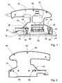
- FIG. 1 shows a schematic representation of an eccentric grinder without a removed cover shell, which in FIG. 2 is shown separately.
- the eccentric grinder comprises a housing element 10 designed as a mounting shell of a housing 12, an electric motor 14 and an output shaft 16 driven by the electric motor 14, which are mounted in the housing element 10, and a plate-shaped oscillating body 18 having a vibration plate 20 provided for grinding surfaces Connection of the oscillating body 18 with the housing element 10 is effected by a connecting means 22 which comprises two separate connecting units 24.
- Each connecting unit 24 has a receiving part 26 and two oscillating elements 28 designed as oscillating legs, each of which is designed with a hexagonal cross-section.
- the oscillating body 18 comprises oscillating element receptacles 30 into which the oscillating elements 28 are inserted in the assembled state of the eccentric grinder.
- the housing element 10 is configured with pocket-shaped cavities 32 into which the receiving parts 26 of the connecting units 24 are inserted. At the edge of each pocket-shaped cavity 32 sit two each a tongue and groove connection with the receiving part 26 producing projections 34.
- the housing member 10 has a plurality of fastener receiving means 36 which are each provided for receiving fastening means 38 which in FIG. 2 are shown.
- FIG. 2 It has a plurality of fastener receptacles 42, which are designed as elevations or seen from the outside as depressions into which the fastening means 38 are inserted from the outside.
- the fastener receptacles 42 are arranged in the cover shell such that when the housing 12 is closed, each fastener receptacle 42 sits opposite one of the fastener receptacles 36 of the mounting shell or the housing element 10 and the fasteners 38, for example screws, can be inserted into the fastener receptacles 36.
- the housing member 40 also includes pocket-shaped cavities 44 which are arranged in the assembled state of the eccentric grinder against the pocket-shaped cavities 32 of the housing member 10 and in which the receiving parts 26 are inserted in the assembled state of the eccentric grinder. At the edge of each pocket-shaped cavity 44 two respective tongue-and-groove connection with the receiving part 26 producing projections 46 are configured.
- the vibrating body 18 is driven by an eccentric, not shown, which is fixed to the output shaft 16.
- the eccentric performs this circular movements that are transmitted to the vibrating body 18.
- the oscillating elements 28 prevent this a rotation of the vibrating body 18 relative to the housing 12 and also hold the vibrating body 18 stable against tilting relative to the housing 12 fixed to the housing 12.
- the vibrating elements 28 are made of a material intended for elastic deformation, for example made of rubber, and allow the Oscillating 18 performs the force imposed by the eccentric oscillating movement relative to the housing 12.
- the inner components i.a. the electric motor 14 and the output shaft 16 are mounted in the housing member 10.
- the receiving parts 26 are inserted into the pocket-shaped cavities 32 of the housing member 10.
- An advantage of the distribution of the connection means 22 in separate connection units 24 is that the connection means 22 can still be easily mounted in the housing element 10 even when the output shaft 16 is already mounted.
- the housing member 40 is placed on the housing member 10, whereby the receiving parts 26 are inserted into the pocket-shaped cavities 44 of the housing member 40.
- the housing member 40 is then replaced by means of the fastener 38, e.g. by screws, attached to the housing member 10, whereby the housing 12 of the eccentric grinder is closed.
- the oscillating elements 28 are each inserted into one of the receiving parts 26. Subsequently, the vibrating elements 28 are pushed by a slight pressing on the vibrating body 18 relative to the housing 12 in the vibrating element receptacles 30 of the vibrating body 18. Finally, the oscillating body 18 is fastened to the eccentric by means of a screw.
- the receiving parts 26 are both with two housing elements 10, 40 and with all the vibrating elements 28 positively connected, whereby these parts can be mounted easily and reliably without errors.
- the housing member 40 formed as a cover shell must be removed to gain access to the internal components.
- the eccentric grinder must not be disassembled analogously to the assembly in the reverse order, but it is sufficient to solve the fastener 38 and lift the cover from the trained as a mounting shell housing element 10.
- the cover shell can be deducted from the receiving parts 26, which remain together with the vibrating elements 28, the oscillating body 18 and the attachment to the eccentric in the mounting cup.
- the attachment of the oscillating body 18 is released on the eccentric, and the vibrating elements 28 are separated by a slight pulling on the oscillating body 18 of the vibrating element receptacles 30 of the oscillating body 18.
- the oscillating elements 28 can then be removed from the receiving parts 26, without the housing element 40 has to be dismantled.
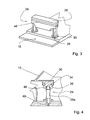
- FIG. 3 shows the connection unit 24 with the two oscillating elements 28, which are inserted in the assembled state of the eccentric grinder in each case in one of the vibrating element receptacles 30 of the oscillating body 18.
- the rotation of the vibrating elements 28 during operation of the eccentric grinder in both the receiving part 26 and in the vibrating element receptacle 30 may cause an undesirable abrasion of, for example, the vibrating elements 28.
- the receiving part 26 has a groove 48 which is arranged parallel to the swing plate 20.
- connection unit 24 is shown mounted in the housing element 10.
- the receiving part 26 is inserted into the pocket-shaped cavity 32 of the housing element 10.
- the receiving part 26 and the housing element 10 and 40 are connected in the assembled state of the eccentric grinder by a tongue and groove connection.
- This contributes to a particularly stable attachment and exact positioning of the receiving part 26 on both housing elements 10, 40 and allows for rapid assembly and disassembly.
- an alternative vibrating element 28a which is hexagonal only in its outer regions and in a central region of circular cross-section. In order to facilitate a pressing of the vibrating element 28a in the vibrating body 18, a vent hole 49 is inserted into the vibrating body.
- FIG. 5 shows the oscillating body 18 facing side of the receiving part 26.
- the receiving part 26 has a receiving means 50 which comprises two recesses 52.
- the recesses 52 are each for receiving one of the oscillating elements 28 provided and are therefore adapted to the hexagonal geometry of the vibrating elements 28.
- the oscillating elements 28 are inserted into the recesses 52, which in turn allows efficient mountability.
Landscapes
- Engineering & Computer Science (AREA)
- Mechanical Engineering (AREA)
- Finish Polishing, Edge Sharpening, And Grinding By Specific Grinding Devices (AREA)
- Apparatuses For Generation Of Mechanical Vibrations (AREA)
- Grinding-Machine Dressing And Accessory Apparatuses (AREA)
Description
- Die Erfindung geht aus von einer Handwerkzeugmaschine nach dem Oberbegriff des Anspruchs 1.
- Aus der
DE 102 51 556 A1 ist eine Handwerkzeugmaschine mit zwei Gehäuseschalen und einer Schwingplatte bekannt, die von einem Exzenter zu seitlichen Schwingbewegungen relativ zu den Gehäuseschalen angetrieben ist. Die Verbindung der Gehäuseschalen mit der Schwingplatte erfolgt mittels zweier elastisch verformbarer Verbindungselemente aus Kunststoff, die in einem Stück aus Kunststoff gefertigt und in den Gehäuseschalen montiert sind. - Die Erfindung geht aus von einer Handwerkzeugmaschine mit einem Gehäuse, einem zur Schwingung relativ zum Gehäuse vorgesehenen Schwingkörper und einem den Schwingkörper an dem Gehäuse befestigenden Verbindungsmittel.
- Das Verbindungsmittel weist ein in das Gehäuse montierbares Aufnahmeteil und ein vom Aufnahmeteil separates und zur Verformung vorgesehenes Schwingelement auf. Diese Teilung des Verbindungsmittels in Aufnahmeteil und separates Schwingelement bietet den Vorteil, dass das Aufnahmeteil und das Schwingelement in einfacher Weise aus verschiedenen Materialien hergestellt werden können und das Material des Aufnahmeteils und das des Schwingelements an die Aufgabe des Aufnahmeteils bzw. des Schwingelements besonders effektiv angepasst werden können. Beispielsweise kann das formgebende und befestigende Aufnahmeteil aus einem festen Kunststoff und das Schwingelement aus einem elastischeren Kunststoff oder einem langlebigen Elastomer hergestellt werden.
- Das Gehäuse weist zwei Gehäuseelemente auf, die durch ein Befestigungsmittel aneinander befestigt sind, wobei durch ein Lösen des Befestigungsmittels eines der Gehäuseelemente vom Schwingkörper abnehmbar ist. Es kann - beispielsweise zum Zweck einer Reparatur - ein einfacher Zugang zu den im Gehäuse angeordneten Komponenten geschaffen werden, ohne dass das abnehmbare Gehäuseelement zusätzlich von dem Verbindungsmittel bzw. dem damit verbundenen Schwingkörper getrennt werden muss. Hierdurch kann eine Reparatur erleichtert werden, und es können Montagefehler nach einer Reparatur der Handwerkzeugmaschine verringert werden.
- Zweckmäßigerweise sind beide Gehäuseelemente in unmittelbarer Umgebung des Verbindungsmittels angeordnet. Beide Gehäuseelemente können durch das Verbindungsmittel stabil mit dem Schwingkörper verbunden werden. Mit gleichem Vorteil sind beide Gehäuseelemente jeweils unabhängig voneinander durch das Verbindungsmittel am Schwingkörper befestigt.
- Eine besonders einfache Montierbarkeit des Verbindungsmittels kann erreicht werden, wenn das Verbindungsmittel zumindest zwei separate Verbindungseinheiten umfasst, die jeweils zumindest ein Aufnahmeteil und zumindest ein Schwingelement aufweisen.
- Das Aufnahmeteil weist ein Aufnahmemittel auf, das zur Aufnahme des Schwingelements bei der Montage des Schwingelements vorgesehen ist. Hierdurch kann eine schnelle Montage des Schwingelements in das Aufnahmeteil erreicht werden. Das Aufnahmemittel kann eine Öffnung sein, in die das Schwingelement eingesteckt oder eingeschraubt sein kann.
- Vorzugsweise bilden das Aufnahmemittel und das Schwingelement im montierten Zustand eine kraftschlüssige Verbindung. Dies bietet den Vorteil, dass eine stabile Befestigung des Verbindungsmittels an dem Aufnahmeteil werkzeuglos erfolgen kann. Außerdem wird hierdurch die Montage erleichtert, da das Schwingelement nach der Verbindung des Schwingelements mit dem Aufnahmeteil kraftschlüssig, also von allein, am oder im Aufnahmeteil gehalten ist und nicht unerwünscht wieder herausfällt.
- Außerdem ist eine formschlüssige Verbindung zwischen dem Aufnahmemittel und dem Schwingelement von Vorteil, die eine Rotation des Schwingelements im Aufnahmemittel verhindet. Es kann ein Verdrehen des Schwingelements und ein hierdurch bewirkter Verschleiß des Schwingelements vermieden werden.
- Es wird außerdem vorgeschlagen, dass das Schwingelement zumindest ein polygonales Schwingbein aufweist. Durch diese bevorzugte Geometrie kann das Verdrehen des Schwingelements im Aufnahmeteil und ein daraus resultierender Abrieb des Schwingelements und gegebenenfalls des Aufnahmeteils verringert werden.
- In einer weiteren Ausgestaltung der Erfindung wird vorgeschlagen, dass das Aufnahmeteil in einen taschenförmigen Hohlraum des Gehäuses eingeschoben ist. Dies bietet den Vorteil, dass das Aufnahmeteil einfach, schnell, werkzeuglos und fehlerfrei in das Gehäuse montiert und aus diesem demontiert werden kann.
- Zweckmäßigerweise ist ein Gehäuseelement vom im anderen Gehäuseelement montierten und dort verbleibenden Aufnahmeteil bei vollständig montiertem Schwingelement abziehbar. Hierdurch kann eine einfache Demontage und Reparatur erreicht werden.
- Eine besonders stabile Befestigung des Aufnahmeteils an dem Gehäuse kann dadurch erreicht werden, dass das Aufnahmeteil und das Gehäuse im montierten Zustand eine Nut-Feder-Verbindung bilden.
- Das Gehäuse weist zwei Gehäuseelemente auf, wobei das Aufnahmeteil in beide Gehäuseelemente einschiebbar ist, insbesondere quer zu einer Exzenterachse. Auf diese Weise kann das Aufnahmeteil besonders einfach in beide Gehäuseelemente montiert werden. Beispielweise wird das Aufnahmeteil zuerst in eine Montageschale eingeschoben, wo andere Komponenten, z.B. Schalter, Motor und Anker, schon angeordnet sind. Anschließend wird eine Deckschale montiert, wobei das Aufnahmeteil vorteilhafterweise in eine Aufnahme der Deckschale einschiebbar ist.
- Zweckmäßigerweise weist jedes Gehäuseelement einen taschenförmigen Hohlraum auf, in den das Aufnahmeteil jeweils separat in einer Montagerichtung einschiebbar ist.
- In einfacher Weise kann eine stabile werkzeuglose Befestigung des Aufnahmeteils an dem Gehäuse dadurch erreicht werden, dass das Aufnahmeteil und das Gehäuse im montierten Zustand eine kraftschlüssige Verbindung bilden.
- In einer weiteren Ausführungsform der Erfindung sind die Schwingelemente bei im Gehäuse angeordnetem - insbesondere eingeschobenem - Aufnahmeteil in das Aufnahmeteil einbringbar. So können defekte Schwingelemente leicht entfernt und ersetzt werden, ohne dass die Gehäuseelemente demontiert werden müssen.
- Dokument
GB 814 793 - Zeichnungsbeschreibung. In der Zeichnung ist ein Ausführungsbeispiel der Erfindung dargestellt. Die Zeichnung, die Beschreibung und die Ansprüche enthalten zahlreiche Merkmale in Kombination.
- Es zeigen:
- Fig. 1
- eine Montageschale, eine Schwingplatte und in der Montageschale montierte innere Komponenten eines Exzenterschleifers mit die Montageschale mit der Schwingplatte verbindenden Verbindungseinheiten,
- Fig. 2
- eine Deckschale des Exzenterschleifers von innen gesehen,
- Fig. 3
- eine Verbindungseinheit mit einem Aufnahmeteil und in das Aufnahmeteil und in die Schwingplatte eingeschobenen Schwingelementen,
- Fig. 4
- eine Detailansicht von
Figur 1 mit der in die Montageschale und in die Schwingplatte eingeschobenen Verbindungseinheit und - Fig. 5
- die der Schwingplatte zugewandte Seite des Aufnahmeteils.
-
Figur 1 zeigt in schematischer Darstellung einen Exzenterschleifer ohne eine abgenommene Deckschale, die inFigur 2 separat dargestellt ist. Der Exzenterschleifer umfasst ein als Montageschale ausgeführtes Gehäuseelement 10 eines Gehäuses 12, einen Elektromotor 14 und eine von dem Elektromotor 14 angetriebene Abtriebswelle 16, die in dem Gehäuseelement 10 montiert sind, sowie einen plattenförmigen Schwingkörper 18 mit einer zum Schleifen von Oberflächen vorgesehenen Schwingplatte 20. Die Verbindung des Schwingkörpers 18 mit dem Gehäuseelement 10 erfolgt durch ein Verbindungsmittel 22, das zwei separate Verbindungseinheiten 24 umfasst. Jede Verbindungseinheit 24 weist ein Aufnahmeteil 26 und zwei als Schwingbeine ausgeführte Schwingelemente 28 auf, die jeweils mit einem hexagonalen Querschnitt ausgestaltet sind. Der Schwingkörper 18 umfasst Schwingelementaufnahmen 30, in den die Schwingelemente 28 im montierten Zustand des Exzenterschleifers eingeschoben sind. - Das Gehäuseelement 10 ist mit taschenförmigen Hohlräumen 32 ausgestaltet, in welche die Aufnahmeteile 26 der Verbindungseinheiten 24 eingeschoben sind. Am Rand jedes taschenförmigen Hohlraums 32 sitzen zwei jeweils eine Nut-Feder-Verbindung mit dem Aufnahmeteil 26 herstellende Vorsprünge 34. Darüber hinaus weist das Gehäuseelement 10 mehrere Befestigungsmittelaufnahmen 36 auf, die jeweils zur Aufnahme von Befestigungsmitteln 38 vorgesehen sind, die in
Figur 2 gezeigt sind. -
Figur 2 zeigt ein als Deckschale ausgeführtes Gehäuseelement 40. Es weist mehrere Befestigungsmittelaufnahmen 42 auf, die als Erhebungen bzw. von außen gesehen als Vertiefungen ausgestaltet sind, in welche die Befestigungsmittel 38 von außen eingeführt sind. Die Befestigungsmittelaufnahmen 42 sind so in der Deckschale angeordnet, dass bei einem Schließen des Gehäuses 12 jede Befestigungsmittelaufnahme 42 gegenüber einer der Befestigungsmittelaufnahmen 36 der Montageschale bzw. des Gehäuseelements 10 sitzt und die Befestigungsmittel 38, beispielweise Schrauben, in die Befestigungsmittelaufnahmen 36 eingeführt werden können. Darüber hinaus umfasst das Gehäuseelement 40 ebenfalls taschenförmige Hohlräume 44, die im montierten Zustand des Exzenterschleifers gegenüber den taschenförmigen Hohlräumen 32 des Gehäuseelements 10 angeordnet sind und in welche die Aufnahmeteile 26 im montierten Zustand des Exzenterschleifers eingeschoben sind. Am Rand jedes taschenförmigen Hohlraums 44 sind zwei jeweils eine Nut-Feder-Verbindung mit dem Aufnahmeteil 26 herstellende Vorsprünge 46 ausgestaltet. - Im Betrieb des Exzenterschleifers wird der Schwingkörper 18 von einem nicht dargestellten Exzenter angetrieben, der an der Abtriebswelle 16 befestigt ist. Der Exzenter vollführt hierbei kreisförmige Bewegungen, die auf den Schwingkörper 18 übertragen werden. Die Schwingelemente 28 verhindern hierbei ein Verdrehen des Schwingkörpers 18 relativ zum Gehäuse 12 und halten zusätzlich den Schwingkörper 18 stabil gegen ein Verkippen relativ zum Gehäuse 12 fest am Gehäuse 12. Die Schwingelemente 28 sind aus einem zur elastischen Deformierung vorgesehenen Material gefertigt, beispielsweise aus Gummi, und erlauben, dass der Schwingkörper 18 die vom Exzenter aufgezwungene Schwingbewegung relativ zum Gehäuse 12 vollführt.
- Bei der Montage des Exzenterschleifers werden zuerst die inneren Komponenten, u.a. der Elektromotor 14 und die Abtriebswelle 16, in das Gehäuseelement 10 montiert. Dann werden die Aufnahmeteile 26 in die taschenförmigen Hohlräume 32 des Gehäuseelements 10 eingeschoben. Ein Vorteil der Verteilung des Verbindungsmittels 22 in separaten Verbindungseinheiten 24 ist, dass das Verbindungsmittel 22 auch dann noch einfach in das Gehäuseelement 10 montiert werden kann, wenn die Abtriebswelle 16 bereits montiert ist. Anschließend wird das Gehäuseelement 40 auf das Gehäuseelement 10 gelegt, wodurch die Aufnahmeteile 26 in die taschenförmigen Hohlräume 44 des Gehäuseelementes 40 eingeschoben werden. Das Gehäuseelement 40 wird dann mithilfe des Befestigungsmittels 38, z.B. durch Schrauben, an dem Gehäuseelement 10 befestigt, wodurch das Gehäuse 12 des Exzenterschleifers geschlossen wird.
- Nun werden die Schwingelemente 28 jeweils in eines der Aufnahmeteile 26 eingeschoben. Anschließend werden die Schwingelemente 28 durch ein leichtes Pressen auf den Schwingkörper 18 relativ zu dem Gehäuse 12 in die Schwingelementaufnahmen 30 des Schwingkörpers 18 eingeschoben. Zum Schluss wird der Schwingkörper 18 mittels einer Schraube an dem Exzenter befestigt. Die Aufnahmeteile 26 sind sowohl mit beiden Gehäuseelementen 10, 40 als auch mit allen Schwingelementen 28 kraftschlüssig verbunden, wodurch diese Teile einfach und zuverlässig fehlerfrei montiert werden können.
- Bei einer Wartung oder einer größeren Reparatur des Exzenterschleifers, um z.B. defekte innere Komponenten des Exzenterschleifers zu reparieren oder zu ersetzen, muss das als Deckschale ausgebildete Gehäuseelement 40 abgenommen werden, um Zugang zu den inneren Komponenten zu erhalten. Hierfür muss nun der Exzenterschleifer nicht analog zur Montage in umgekehrter Reihenfolge demontiert werden, sondern es reicht aus, die Befestigungsmittel 38 zu lösen und die Deckschale von dem als Montageschale ausgebildeten Gehäuseelement 10 abzuheben. Hierbei kann die Deckschale von den Aufnahmeteilen 26 abgezogen werden, die zusammen mit den Schwingelementen 28, dem Schwingkörper 18 und der Befestigung am Exzenter in der Montageschale verbleiben.
- Zu einem Wechsel der Schwingelemente 28, beispielsweise wenn diese erneuert werden sollen, wird die Befestigung des Schwingkörpers 18 am Exzenter gelöst, und die Schwingelemente 28 werden durch ein leichtes Ziehen am Schwingkörper 18 von den Schwingelementaufnahmen 30 des Schwingkörpers 18 getrennt. Die Schwingelemente 28 können dann von den Aufnahmeteilen 26 abgezogen werden, ohne dass das Gehäuseelement 40 demontiert werden muss.
-
Figur 3 zeigt die Verbindungseinheit 24 mit den zwei Schwingelementen 28, die im montierten Zustand des Exzenterschleifers jeweils in eine der Schwingelementaufnahmen 30 des Schwingkörpers 18 eingeschoben sind. Wenn runde Schwingelemente 28 benutzt werden, kann das Verdrehen der Schwingelemente 28 im Betrieb des Exzenterschleifers sowohl im Aufnahmeteil 26 als auch in der Schwingelementaufnahme 30 einen unerwünschten Abrieb an z.B. den Schwingelementen 28 verursachen. Durch die Wahl einer polygonalen Geometrie der Schwingelemente 28, die hexagonal ausgeführt sind, kann erreicht werden, dass dieser Abrieb erheblich reduziert wird, was eine längere Lebensdauer der Schwingelemente 28 ermöglicht. Darüber hinaus weist das Aufnahmeteil 26 eine Nut 48 auf, die parallel zur Schwingplatte 20 angeordnet ist. - In
Figur 4 ist die Verbindungseinheit 24 in dem Gehäuseelement 10 montiert dargestellt. Das Aufnahmeteil 26 ist in den taschenförmigen Hohlraum 32 des Gehäuseelements 10 eingeschoben. Durch die Nut 48 des Aufnahmeteils 26 und die Vorsprünge 34 bzw. 46 werden das Aufnahmeteil 26 und das Gehäuseelement 10 bzw. 40 im montierten Zustand des Exzenterschleifers durch eine Nut-Feder-Verbindung verbunden. Dies trägt zu einer besonders stabilen Befestigung und exakten Positionierung des Aufnahmeteils 26 an beiden Gehäuseelementen 10, 40 bei und ermöglicht eine schnelle Montage und Demontage. Es ist außerdem ein alternatives Schwingelement 28a gezeigt, das lediglich in seinen äußeren Bereichen hexagonal und in einem mittleren Bereich mit rundem Querschnitt ausgeführt ist. Um ein Einpressen des Schwingelements 28a in den Schwingkörper 18 zu erleichtern, ist eine Entlüftungsbohrung 49 in den Schwingkörper eingebracht. -
Figur 5 zeigt die dem Schwingkörper 18 zugewandte Seite des Aufnahmeteils 26. Das Aufnahmeteil 26 weist ein Aufnahmemittel 50 auf, das zwei Aussparungen 52 umfasst. Die Aussparungen 52 sind jeweils zur Aufnahme eines der Schwingelemente 28 vorgesehen und sind daher der hexagonalen Geometrie der Schwingelemente 28 angepasst. Bei der Montage sind die Schwingelemente 28 in die Aussparungen 52 eingeschoben, was wiederum eine effiziente Montierbarkeit erlaubt.
Claims (7)
- Handwerkzeugmaschine mit einem Gehäuse (12), einem zur Schwingung relativ zum Gehäuse (12) vorgesehenen Schwingkörper (18) und einem den Schwingkörper (18) an dem Gehäuse (12) befestigenden Verbindungsmittel (22), wobei das Verbindungsmittel (22) ein in das Gehäuse (12) montierbares Aufnahmeteil (26) und ein vom Aufnahmeteil (26) separates und zur Verformung vorgesehenes Schwingelement (28) aufweist, wobei das Gehäuse (12) zwei Gehäuseelemente (10, 40) aufweist, die durch ein Befestigungsmittel (38) aneinander befestigt sind, wobei eines der Gehäuseelemente (10, 40) als Montageschale und eines der Gehäuseelemente (10, 40) als Deckschale ausgebildet ist, wobei durch ein Lösen des Befestigungsmittels (38) eines der Gehäuseelemente (10, 40) vom Schwingkörper (18) abnehmbar ist, wobei das Aufnahmeteil (26) ein Aufnahmemittel (50) aufweist, das zur Aufnahme des Schwingelements (28) bei der Montage des Schwingelements (28) vorgesehen ist, dadurch gekennzeichnet, dass das Aufnahmeteil (26) in beide Gehäuseelemente (10, 40) einschiebbar ist, wobei durch das Lösen des Befestigungsmittels (38) die Deckschale von der Montageschale abhebbar ist, wodurch die Deckschale von dem Aufnahmeteil (26) abziehbar ist.
- Handwerkzeugmaschine nach Anspruch 1, dadurch gekennzeichnet, dass das Verbindungsmittel (22) zumindest zwei separate Verbindungseinheiten (24) umfasst, die jeweils zumindest ein Aufnahmeteil (26) und zumindest ein Schwingelement (28) aufweisen.
- Handwerkzeugmaschine nach Anspruch 1 oder 2, dadurch gekennzeichnet, dass das Aufnahmemittel (50) und das Schwingelement (28) im montierten Zustand eine kraftschlüssige Verbindung bilden.
- Handwerkzeugmaschine nach einem der vorhergehenden Ansprüche, dadurch gekennzeichnet, dass das Schwingelement (28) zumindest ein polygonales Schwingbein aufweist.
- Handwerkzeugmaschine nach einem der vorhergehenden Ansprüche, dadurch gekennzeichnet, dass das Aufnahmeteil (26) in einen taschenförmigen Hohlraum (32, 44) des Gehäuses (12) eingeschoben ist.
- Handwerkzeugmaschine nach einem der vorhergehenden Ansprüche, dadurch gekennzeichnet, dass das Aufnahmeteil (26) und das Gehäuse (12) im montierten Zustand eine kraftschlüssige Verbindung bilden.
- Handwerkzeugmaschine nach einem der vorhergehenden Ansprüche, dadurch gekennzeichnet, dass die Schwingelemente (28) bei in dem Gehäuse (12) eingeschobenem Aufnahmeteil (26) in das Aufnahmeteil (26) einbringbar sind.
Applications Claiming Priority (2)
| Application Number | Priority Date | Filing Date | Title |
|---|---|---|---|
| DE102005009739A DE102005009739A1 (de) | 2005-03-03 | 2005-03-03 | Handwerkzeugmaschine |
| PCT/EP2006/050047 WO2006092341A1 (de) | 2005-03-03 | 2006-01-05 | Handwerkzeugmaschine |
Publications (2)
| Publication Number | Publication Date |
|---|---|
| EP1858668A1 EP1858668A1 (de) | 2007-11-28 |
| EP1858668B1 true EP1858668B1 (de) | 2010-04-21 |
Family
ID=35999584
Family Applications (1)
| Application Number | Title | Priority Date | Filing Date |
|---|---|---|---|
| EP06700757A Expired - Lifetime EP1858668B1 (de) | 2005-03-03 | 2006-01-05 | Handwerkzeugmaschine |
Country Status (5)
| Country | Link |
|---|---|
| US (1) | US7867065B2 (de) |
| EP (1) | EP1858668B1 (de) |
| CN (1) | CN101132883B (de) |
| DE (2) | DE102005009739A1 (de) |
| WO (1) | WO2006092341A1 (de) |
Families Citing this family (2)
| Publication number | Priority date | Publication date | Assignee | Title |
|---|---|---|---|---|
| RU2013119819A (ru) * | 2010-10-04 | 2014-11-20 | Роберт Бош Гмбх | Осциллирующая ручная машина |
| CN115070576B (zh) * | 2022-07-18 | 2024-04-12 | 上海司珏实业有限公司 | 砂光机 |
Family Cites Families (15)
| Publication number | Priority date | Publication date | Assignee | Title |
|---|---|---|---|---|
| GB814793A (en) | 1957-04-24 | 1959-06-10 | Sundstrand Machine Tool Co | Rubbing machine |
| US3336702A (en) * | 1964-02-28 | 1967-08-22 | Black & Decker Mfg Co | Oscillating platen for abrading tool |
| US3849943A (en) * | 1973-02-26 | 1974-11-26 | Rockwell International Corp | Power operated sanding machine |
| US3900974A (en) * | 1974-02-14 | 1975-08-26 | Singer Co | Portable surface-treating machine with improved platen-mounting construction |
| US3862520A (en) * | 1974-02-14 | 1975-01-28 | Singer Co | Support assembly for a portable surface-treating machine |
| US3918214A (en) * | 1974-10-02 | 1975-11-11 | Mc Graw Edison Co | Vibrating sander |
| US4095375A (en) * | 1977-03-16 | 1978-06-20 | The Singer Company | Support assembly for a portable surface-treating machine |
| US4414782A (en) * | 1981-09-01 | 1983-11-15 | Black & Decker Inc. | Direct drive system for a turbine sander |
| DE3421020A1 (de) * | 1984-06-06 | 1985-12-12 | Licentia Patent-Verwaltungs-Gmbh, 6000 Frankfurt | Schwingschleifer mit einem zweischalengehaeuse |
| JPS6161761A (ja) * | 1984-08-29 | 1986-03-29 | Makita Denki Seisakusho:Kk | コ−ドレス研摩機 |
| US4686797A (en) * | 1986-10-15 | 1987-08-18 | National Air Sander, Inc. | Straight-line rubbing machine with thrust transmitting members |
| US4837981A (en) * | 1987-07-06 | 1989-06-13 | Ryobi Limited | Power operated sanding machine |
| US5206967A (en) * | 1989-12-27 | 1993-05-04 | Makita Electric Works, Ltd. | Electric wax applicator |
| US20050164515A9 (en) * | 2001-06-05 | 2005-07-28 | Belcher Angela M. | Biological control of nanoparticle nucleation, shape and crystal phase |
| DE10251556A1 (de) | 2002-11-06 | 2004-05-19 | Robert Bosch Gmbh | Lageranordnung zur schwingfähigen Lagerung eines Schleiftellers an einem Schleifgerät |
-
2005
- 2005-03-03 DE DE102005009739A patent/DE102005009739A1/de not_active Withdrawn
-
2006
- 2006-01-05 CN CN200680006905.3A patent/CN101132883B/zh not_active Expired - Lifetime
- 2006-01-05 DE DE502006006790T patent/DE502006006790D1/de not_active Expired - Lifetime
- 2006-01-05 US US11/571,167 patent/US7867065B2/en not_active Expired - Fee Related
- 2006-01-05 WO PCT/EP2006/050047 patent/WO2006092341A1/de not_active Ceased
- 2006-01-05 EP EP06700757A patent/EP1858668B1/de not_active Expired - Lifetime
Also Published As
| Publication number | Publication date |
|---|---|
| US7867065B2 (en) | 2011-01-11 |
| WO2006092341A1 (de) | 2006-09-08 |
| DE502006006790D1 (de) | 2010-06-02 |
| CN101132883B (zh) | 2014-02-19 |
| CN101132883A (zh) | 2008-02-27 |
| EP1858668A1 (de) | 2007-11-28 |
| DE102005009739A1 (de) | 2006-09-07 |
| US20080070487A1 (en) | 2008-03-20 |
Similar Documents
| Publication | Publication Date | Title |
|---|---|---|
| DE102014103048B4 (de) | Elektrowerkzeug aufweisend ein Bauteil zur Herstellung einer formschlüssigen Nietverbindung eines Werkzeugs | |
| DE202012100860U1 (de) | Verbindungsanordnung einer schnelllösbaren Verlängerungsstange | |
| DE102008006030A1 (de) | Handwerkzeugmaschine, insbesondere elektrisch betriebene Handwerkzeugmaschine | |
| EP1554068B1 (de) | Abstreifeinrichtung | |
| DE202010008240U1 (de) | Multifunktions-Kraftwerkzeug | |
| DE202008007730U1 (de) | Elektrischer Schwingantrieb | |
| DE102010039637A1 (de) | Handwerkzeugmaschine mit einem Spannhals | |
| DE102009010718A1 (de) | Befestigungsvorrichtung | |
| EP2655018A1 (de) | Handwerkzeugmaschine | |
| EP1858668A1 (de) | Handwerkzeugmaschine | |
| EP3856401A1 (de) | Schüttel- und/oder mischgerät | |
| DE102008000728A1 (de) | Handwerkzeugmaschine, insbesondere handgeführte Schleifmaschine | |
| DE102008001252A1 (de) | Werkzeugmaschine, insbesondere Handwerkzeugmaschine | |
| EP4344783A1 (de) | Statorteil einer prallmühle und befestigungsverfahren | |
| DE29818204U1 (de) | Elektromotorischer Möbelantrieb | |
| WO2012089637A2 (de) | Handwerkzeugmaschinenspannvorrichtung | |
| DE202008006678U1 (de) | Elektromesser | |
| DE10251556A1 (de) | Lageranordnung zur schwingfähigen Lagerung eines Schleiftellers an einem Schleifgerät | |
| EP3085496B1 (de) | Pendelspannbacke und spannvorrichtung mit einer solchen pendelspannbacke | |
| DE102014001538B3 (de) | Handwerkzeugmaschine, insbesondere eine Heckenschere | |
| EP2804710B1 (de) | Vorrichtung zum entkernen von gusskörpern | |
| DE102011075586A1 (de) | Schleiftellervorrichtung für ein handgeführtes Schleifgerät | |
| DE202007000647U1 (de) | Struktur einer pneumatischen Schleifmaschine | |
| EP3736093A1 (de) | Befestigungsvorrichtung zum befestigen eines kettensägenschwerts | |
| DE102024104418A1 (de) | Schneidwerkzeug, insbesondere Schere, mit federnd gegeneinander vorgespannten Klingen |
Legal Events
| Date | Code | Title | Description |
|---|---|---|---|
| PUAI | Public reference made under article 153(3) epc to a published international application that has entered the european phase |
Free format text: ORIGINAL CODE: 0009012 |
|
| 17P | Request for examination filed |
Effective date: 20071004 |
|
| AK | Designated contracting states |
Kind code of ref document: A1 Designated state(s): DE FR GB |
|
| RBV | Designated contracting states (corrected) |
Designated state(s): DE FR GB |
|
| DAX | Request for extension of the european patent (deleted) | ||
| 17Q | First examination report despatched |
Effective date: 20080602 |
|
| GRAP | Despatch of communication of intention to grant a patent |
Free format text: ORIGINAL CODE: EPIDOSNIGR1 |
|
| GRAS | Grant fee paid |
Free format text: ORIGINAL CODE: EPIDOSNIGR3 |
|
| GRAA | (expected) grant |
Free format text: ORIGINAL CODE: 0009210 |
|
| AK | Designated contracting states |
Kind code of ref document: B1 Designated state(s): DE FR GB |
|
| REG | Reference to a national code |
Ref country code: GB Ref legal event code: FG4D Free format text: NOT ENGLISH |
|
| REF | Corresponds to: |
Ref document number: 502006006790 Country of ref document: DE Date of ref document: 20100602 Kind code of ref document: P |
|
| PLBE | No opposition filed within time limit |
Free format text: ORIGINAL CODE: 0009261 |
|
| STAA | Information on the status of an ep patent application or granted ep patent |
Free format text: STATUS: NO OPPOSITION FILED WITHIN TIME LIMIT |
|
| 26N | No opposition filed |
Effective date: 20110124 |
|
| PGFP | Annual fee paid to national office [announced via postgrant information from national office to epo] |
Ref country code: GB Payment date: 20120124 Year of fee payment: 7 |
|
| PGFP | Annual fee paid to national office [announced via postgrant information from national office to epo] |
Ref country code: FR Payment date: 20130207 Year of fee payment: 8 |
|
| GBPC | Gb: european patent ceased through non-payment of renewal fee |
Effective date: 20130105 |
|
| PG25 | Lapsed in a contracting state [announced via postgrant information from national office to epo] |
Ref country code: GB Free format text: LAPSE BECAUSE OF NON-PAYMENT OF DUE FEES Effective date: 20130105 |
|
| REG | Reference to a national code |
Ref country code: FR Ref legal event code: ST Effective date: 20140930 |
|
| PG25 | Lapsed in a contracting state [announced via postgrant information from national office to epo] |
Ref country code: FR Free format text: LAPSE BECAUSE OF NON-PAYMENT OF DUE FEES Effective date: 20140131 |
|
| REG | Reference to a national code |
Ref country code: DE Ref legal event code: R084 Ref document number: 502006006790 Country of ref document: DE |
|
| PGFP | Annual fee paid to national office [announced via postgrant information from national office to epo] |
Ref country code: DE Payment date: 20250317 Year of fee payment: 20 |
|
| REG | Reference to a national code |
Ref country code: DE Ref legal event code: R071 Ref document number: 502006006790 Country of ref document: DE |