EP1857784A2 - Sensor of an electromagnetic mass flow meter - Google Patents
Sensor of an electromagnetic mass flow meter Download PDFInfo
- Publication number
- EP1857784A2 EP1857784A2 EP07108382A EP07108382A EP1857784A2 EP 1857784 A2 EP1857784 A2 EP 1857784A2 EP 07108382 A EP07108382 A EP 07108382A EP 07108382 A EP07108382 A EP 07108382A EP 1857784 A2 EP1857784 A2 EP 1857784A2
- Authority
- EP
- European Patent Office
- Prior art keywords
- measuring tube
- interior
- hermetically sealed
- sensor
- measuring
- Prior art date
- Legal status (The legal status is an assumption and is not a legal conclusion. Google has not performed a legal analysis and makes no representation as to the accuracy of the status listed.)
- Withdrawn
Links
Images


Classifications
-
- G—PHYSICS
- G01—MEASURING; TESTING
- G01F—MEASURING VOLUME, VOLUME FLOW, MASS FLOW OR LIQUID LEVEL; METERING BY VOLUME
- G01F15/00—Details of, or accessories for, apparatus of groups G01F1/00 - G01F13/00 insofar as such details or appliances are not adapted to particular types of such apparatus
- G01F15/14—Casings, e.g. of special material
-
- G—PHYSICS
- G01—MEASURING; TESTING
- G01F—MEASURING VOLUME, VOLUME FLOW, MASS FLOW OR LIQUID LEVEL; METERING BY VOLUME
- G01F1/00—Measuring the volume flow or mass flow of fluid or fluent solid material wherein the fluid passes through a meter in a continuous flow
- G01F1/56—Measuring the volume flow or mass flow of fluid or fluent solid material wherein the fluid passes through a meter in a continuous flow by using electric or magnetic effects
- G01F1/58—Measuring the volume flow or mass flow of fluid or fluent solid material wherein the fluid passes through a meter in a continuous flow by using electric or magnetic effects by electromagnetic flowmeters
- G01F1/588—Measuring the volume flow or mass flow of fluid or fluent solid material wherein the fluid passes through a meter in a continuous flow by using electric or magnetic effects by electromagnetic flowmeters combined constructions of electrodes, coils or magnetic circuits, accessories therefor
Definitions
- the invention relates to a sensor of a magnetic inductive flowmeter.
- Flowmeters are used in industrial measurement technology for the measurement of volume flows.
- a current measurement method is based on the magneto-hydrodynamic principle and is used in magnetic-inductive flow sensors.
- an at least to a small extent electrically conductive medium whose volume flow is to be measured passed through a measuring tube which is penetrated substantially perpendicular to the tube axis of a magnetic field.
- Perpendicular to the magnetic field moving charge carriers induce perpendicular to their flow direction, a voltage which can be tapped via appropriately arranged measuring electrodes.
- the measuring electrodes are either capacitively or galvanically coupled to the medium. The induced voltage is proportional to averaged over a cross section of the measuring tube flow velocity of the medium and thus proportional to the volume flow.
- magneto-inductive sensors regularly have a sensor housing connected to the measuring tube, which surrounds at least a part of the measuring tube, and in the usual way the mounted on the measuring tube device for generating the measuring tube passing through the magnetic field, the connecting lines, and connecting lines for the electrodes are arranged ,
- the individual components are regularly made of different materials and are usually connected to each other with the interposition of appropriate seals.
- Magnetic inductive flowmeters are often exposed to very large temperature fluctuations in industrial applications. Since conventional seals usually close pressure-tight but not gas-tight, temperature changes can cause very humid air from the environment to penetrate into the sensor housing or even sucked in, and it precipitates moisture contained in the housing. The condensate can then no longer escape.
- the invention consists in a sensor of a magnetic inductive flowmeter for measuring a flow of a medium through an existing piping system, with
- a measuring tube made of a plastic whose interior in the measuring mode
- the medium induced voltage can be tapped
- a sensor housing made of a plastic
- the hermetically sealed joints are plastic welds or bonds.
- connection space adjacent to the sensor housing a connection space, the interior of which completely from the interior of the
- Hermetically sealed bushings are provided over which the connecting leads of the device for generating the magnetic field and the electrodes are guided into the connection space in a measuring sensor housing which is separated from the interior of the Meßaufêtgephinuses from the terminal compartment.
- connection space is formed by a cap-shaped attachment made of a plastic, which is hermetically sealed to a formed on the Meßaufrichgeophuse, the bushings surrounding base.
- connection space is filled with a potting compound.
- a connector is arranged at the connection space, via which the connection lines guided into the connection space can be contacted from the outside.
- the sensor housing has a hollow cylinder, on which on opposite sides an inlet and an outlet for the medium is formed.
- the measuring tube is arranged in the hollow cylinder such that it runs perpendicular to a longitudinal axis of the hollow cylinder and connects the inlet to the outlet.
- Each end of the measuring tube is hermetically sealed to the hollow cylinder by means of a hermetically sealed connection, in particular a plastic weld or a bond, and the interior of the sensor housing is sealed by the hermetically sealed connection closed to the interior of the measuring tube, the inlet and the outlet.
- An advantage of the invention is that the interior of the sensor housing is completely hermetically sealed against the measuring tube and the environment. This ensures that no gas exchange with the environment can take place. Accordingly, the interior is protected from penetrating moisture.
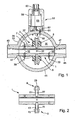
- Fig. 1 shows a magnetic inductive according to the invention
- Fig. 2 shows the measuring tube of Figure 1 in section.
- Fig. 3 shows a view of the Feldleitelements of Fig. 1;
- Fig. 4 shows a sectional view of the measuring tube 1 in the plane of
- Fig. 5 is a view of the flowmeter of Fig. 1;
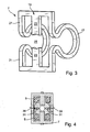
- Fig. 6 shows a section of the flow sensor shown in Fig. 1
- FIG. 7 shows a view of the sensor of FIG. 6.
- FIG. 1 shows an exemplary embodiment of a sensor according to the invention of a magneto-inductive flowmeter for measuring a flow of a medium through an existing one Piping system.
- the sensor has a measuring tube 1 shown in detail in FIG. 2, the interior of which flows through the medium during measuring operation.
- the measuring tube 1 is inserted via, not shown in Fig. 1, process connections in the existing pipeline system.
- the measuring tube 1 completely made of a plastic.
- thermoplastics such as polyetheretherketone (PEEK), polyvinylidene fluoride (PVDF), polyethylene (PE) or polyamide (PA) are used.
- Plastics are insulators. This offers, inter alia, the advantage that no insulating lining, such as the aforementioned liner, of the measuring tube 1 is required. Accordingly, no medium and no gas between meter tube and lining penetrate.
- the senor comprises a mounted on the measuring tube 1 device 3 for generating a measuring tube 1 at least partially passing magnetic field.
- the device 3 comprises in the illustrated embodiment, two diametrically opposite to the measuring tube 1 fixed coils 5 and a one-piece Feldleitelement 7 made of a magnetically conductive material, which serves to guide the magnetic field outside of the measuring tube 1.
- each holder 9 comprises two mutually parallel arranged directly on the measuring tube 1 integrally formed locking elements 11, which have a straight portion 13 with rectangular cross section, to the ends of a tapered in measuring tube-facing direction shoulder 15 connects.
- the coils 5 are substantially hollow cylindrical and are attached to the two locking elements 11. When assembled, the coils 5 surround the straight portions 13 coaxially and are fixed in position by the adjacent heels 15.
- the Feldleitelement 7 consists of a resilient material and is inserted into the brackets 9. In this case, the Feldleitelement 7 is pushed onto the measuring tube 1 and it is the two middle crossbars 23 inserted into a gap 27 between the two Rastelelementen 11 of the respective holder 9.
- the Feldleitelements 7 is additionally provided at each locking element 11 at the end a in the gap 27 facing in locking lug 29 which engage in the assembled state respectively behind the trunk of the respective E-shaped member 21.
- electrodes 31 are inserted into corresponding holes. This is on the EP 0 892 252 A1 directed. There, a liquid-tight installation of electrodes is described, which is achieved for example in that the electrodes are provided with successive truncated cone-shaped sections in which the material of the measuring tube 1 digs.
- the electrodes 31 inserted into the measuring tube 1 serve to pick up a voltage induced in the medium during measuring operation.
- two electrodes 31 are provided, which are inserted opposite each other in such a way in the measuring tube 1, that an imaginary between the electrodes 31 connecting line perpendicular to an imaginary between the two coils 5 connecting line and thus perpendicular to the magnetic field. 4 shows a sectional drawing of the measuring tube 1 in the plane of the electrodes 31.
- the sensor has a sensor housing 33 made of a plastic, which has a hermetically sealed closed interior 35 has.
- the same material is used here, which is also used for the measuring tube 1.
- the measuring tube 1 is wholly or partially inserted by means of a hermetically sealed connection in the Meßaufêtgeophuse 33 that the interior of the measuring tube 1 inlet and outlet side accessible, and the interior 35 of the Meßerkumblegephinuses 33 with respect to the interior of the measuring tube and the environment of the sensor hermetically is tightly closed. This is particularly possible because the hermetically sealed parts to be joined together, the sensor housing 33 and the measuring tube 1 are both made of plastic.
- the hermetically sealed connections between the affected segments to be connected of the sensor housing 33 and the measuring tube 1 are preferably produced by plastic welding or by gluing.
- the device 3 for generating the magnetic field In the interior 35 of the sensor housing 33 are the device 3 for generating the magnetic field, the connecting lines 37, and connecting lines 39 for the electrodes 31, 32.
- electrical and / or mechanical components such as a suburb electronics, be included.
- the sensor housing 33 shown in FIG. 1 has a hollow cylinder 41, on which on opposite sides an inlet 43 and an outlet 45 for the medium are formed.
- Inlet 43 and outlet 45 are each formed by an integrally formed on the hollow cylinder 41 in the interior of the hollow cylinder 41 opening pipe segment.
- the measuring tube 1 is in this embodiment completely in the sensor housing 33 and is arranged in the hollow cylinder 41 such that it is perpendicular to a longitudinal axis of the hollow cylinder and the inlet 43 connects to the outlet 45.
- a mouth 43 of the inlet 43 and another mouth of the outlet coaxially tightly enclosing recess 47 is provided, in which the respective ends of the measuring tube 1 are inserted such that an inner circumferential surface of the measuring tube 1 is flush with the adjoining inner lateral surfaces the inlet 43 and the outlet 45 closes.
- Both ends of the measuring tube 1 are inserted into the respective recesses 47 by means of a hermetically sealed connection, eg welded or glued.
- a hermetically sealed connection eg welded or glued.
- This connection is produced, for example, by completely fitting the measuring tube 1 with the electrodes 31, 32, the coils 5 and the field-guiding system 7.
- the hollow cylinder 41 is compressed perpendicular to the direction of flow. This leads to an expansion of the hollow cylinder 41 in the direction of flow.
- Measuring tube 1 and hollow cylinder 41 are warmed, for example, and it is that the measuring tube 1 is inserted into the compressed hollow cylinder 41, and there welded or glued.
- the sensor housing 7 comprises two substantially circular disc-shaped cover 49, which are applied by means of a hermetically sealed connection, esp. A plastic weld or a bond, on two opposite annular end faces of the hollow cylinder 41. 5 shows a view of the sensor housing 33.
- the interior 35 of the sensor housing 33 is completely self-contained and closed to the outside by the measuring tube 1 which is hermetically sealed therein.
- the measuring tube 1 which is hermetically sealed therein.
- connection space 51 Adjoining the sensor housing 41 is a connection space 51, the interior 53 of which is surrounded by an outer wall 55 of the housing Sensor housing 41 is completely separated from the interior 35 of the sensor housing 41.
- this outer space 55 of the sensor housing which separates the interior 35 of the sensor housing 41 from the connection space 51, hermetically sealed passages 57 are provided, via which the connection lines 37 of the device 3 for generating the magnetic field and connection lines 39 of the electrodes 31, 32 are led into the connection space 51.
- the passages 57 are preferably just like the electrodes 31, 32 equipped with successive truncated cone-shaped sections in which the material of the outer wall 55 digs.
- the terminal space 51 is preferably formed by a cap-shaped attachment 59 made of a plastic, which is hermetically sealed to a formed on the Meßaufrichgeophuse 41, the bushings 57 surrounding base 61. Again, the same material is preferably used, which is also used for the measuring tube 1 and the sensor housing 41.
- the hermetically sealed connection is preferably a plastic weld or a bond.
- connection lines 37, 39 are guided via the passages 57 into the connection space 51 and are connected there to a connector 63 arranged on the connection space 51, via which they can be contacted from the outside.
- the remaining space in the connection space 53 cavity is preferably filled with a potting compound. In this way, it is ensured that the connection space 53 is protected from the ingress of moisture.
- Fig. 1 may be equipped with a variety of different process connections.
- Fig. 6 shows a section and
- Fig. 7 is a view of the sensor of Fig. 1 in which at the inlet 43 and at the outlet 45 plastic flanges 65 are formed.
- Other types of process connections can also be used and can be formed directly on inlet 43 and outlet 45.
- the process connections directly to mold to the measuring tube.
- a sensor housing that hermetically encloses a portion of the measuring tube between the process connections.
- This housing may, for example, have two housing halves, which are hermetically sealed together, in particular welded or glued.
- the measuring tube is in this case through the housing and is there, where it enters the hermetically sealed into the housing or to connect to the housing, for example, to be welded or glued. This also makes it possible to achieve a hermetically sealed interior of the sensor housing.
Abstract
Description
Die Erfindung betrifft einen Messaufnehmer eines magnetisch induktiven Durchflussmessgeräts.The invention relates to a sensor of a magnetic inductive flowmeter.
Durchflussmessgeräte werden in der industriellen Messtechnik zur Messung von Volumenströmen eingesetzt.Flowmeters are used in industrial measurement technology for the measurement of volume flows.
Ein heute gängiges Messverfahren beruht auf dem magneto-hydrodynamischen Prinzip und wird in magnetisch induktiven Durchflussmessaufnehmern eingesetzt. Dabei wird ein zumindest in geringem Umfang elektrisch leitfähiges Medium, dessen Volumenstrom gemessen werden soll, durch ein Messrohr geleitet, das im wesentlichen senkrecht zur Rohrachse von einem Magnetfeld durchsetzt ist. Senkrecht zum Magnetfeld bewegte Ladungsträger induzieren senkrecht zu deren Durchflussrichtung eine Spannung, die über entsprechend angeordnete Messelektroden abgreifbar ist. Die Messelektroden sind hierzu mit dem Medium entweder kapazitiv oder galvanisch gekoppelt. Die induzierte Spannung ist proportional zu einer über einen Querschnitt des Messrohres gemittelten Strömungsgeschwindigkeit des Mediums und damit proportional zum Volumenstrom.A current measurement method is based on the magneto-hydrodynamic principle and is used in magnetic-inductive flow sensors. In this case, an at least to a small extent electrically conductive medium whose volume flow is to be measured, passed through a measuring tube which is penetrated substantially perpendicular to the tube axis of a magnetic field. Perpendicular to the magnetic field moving charge carriers induce perpendicular to their flow direction, a voltage which can be tapped via appropriately arranged measuring electrodes. For this purpose, the measuring electrodes are either capacitively or galvanically coupled to the medium. The induced voltage is proportional to averaged over a cross section of the measuring tube flow velocity of the medium and thus proportional to the volume flow.
Handelsübliche magnetisch induktive Messaufnehmer weisen regelmäßig ein mit dem Messrohr verbundenes Messaufnehmergehäuse auf, das zumindest einen Teil des Messrohres umgibt, und in dem üblicher Weise die am Messrohr montierte Vorrichtung zur Erzeugung des das Messohr durchsetzenden Magnetfelds, deren Anschlussleitungen, sowie Anschlussleitungen für die Elektroden angeordnet sind. Die einzelnen Komponenten bestehen regelmäßig aus unterschiedlichen Materialien und sind in der Regel unter Zwischenfügung entsprechender Dichtungen miteinander verbunden.Commercially available magneto-inductive sensors regularly have a sensor housing connected to the measuring tube, which surrounds at least a part of the measuring tube, and in the usual way the mounted on the measuring tube device for generating the measuring tube passing through the magnetic field, the connecting lines, and connecting lines for the electrodes are arranged , The individual components are regularly made of different materials and are usually connected to each other with the interposition of appropriate seals.
Magnetisch induktive Durchflussmessgeräte werden in industriellen Anwendungen häufig sehr großen Temperaturschwankungen ausgesetzt. Da herkömmliche Dichtungen in der Regel druckdicht aber nicht gasdicht schließen, kann es durch Temperaturwechsel dazu kommen, dass sehr feuchte Luft aus der Umgebung in das Messaufnehmergehäuse eindringt oder sogar eingesaugt wird, und sich darin enthaltene Feuchtigkeit im Gehäuse niederschlägt. Das Kondensat kann dann nicht mehr entweichen. Man spricht in diesem Zusammenhang auch von einem so genannten Pumpeffekt. Feuchtigkeit im Messaufnehmergehäuse kann zu einer erheblichen Beeinträchtigung der Funktionalität des Messaufnehmers führen.Magnetic inductive flowmeters are often exposed to very large temperature fluctuations in industrial applications. Since conventional seals usually close pressure-tight but not gas-tight, temperature changes can cause very humid air from the environment to penetrate into the sensor housing or even sucked in, and it precipitates moisture contained in the housing. The condensate can then no longer escape. One speaks in this context of a so-called pumping effect. Moisture in the sensor housing can lead to a significant impairment of the functionality of the sensor.
Ein ähnliches Problem tritt in Verbindung mit metallischen Messrohren auf, die innen mit einem elektrisch nicht leitenden Isoliermaterial, dem so genannten Liner, beschichtet ist. Hier kann es zu einer Hinterwanderung des Liners kommen, bei der Luft oder Gas aus der Umgebung und/oder Medium zwischen dem Liner und dem Messrohr eindringt. Dies kann ebenfalls die Funktionalität des Messaufnehmers beeinträchtigen.A similar problem occurs in connection with metallic measuring tubes, which is internally coated with an electrically non-conductive insulating material, the so-called liner. This can lead to a back migration of the liner, penetrates the air or gas from the environment and / or medium between the liner and the measuring tube. This can also affect the functionality of the sensor.
Es ist eine Aufgabe der Erfindung einen vor eindringender Feuchtigkeit geschützten magnetisch induktiven Durchflussmessaufnehmer anzugeben.It is an object of the invention to provide a magnetically inductive flow sensor protected against moisture intrusion.
Hierzu besteht die Erfindung in einem Messaufnehmer eines magnetisch induktiven Durchflussmessgeräts zum Messen eines Durchflusses eines Mediums durch ein bestehendes Rohrleitungssystem, mitFor this purpose, the invention consists in a sensor of a magnetic inductive flowmeter for measuring a flow of a medium through an existing piping system, with
- einem Messrohr aus einem Kunststoff, dessen Innenraum im Messbetrieb- A measuring tube made of a plastic whose interior in the measuring mode
vom Medium durchströmt wird,flowing through the medium,
- einer am Messrohr montierten Vorrichtung zur Erzeugung eines das- A device mounted on the measuring tube for generating a the
Messohr durchsetzenden Magnetfelds,Measuring tube penetrating magnetic field,
- in das Messrohr eingesetzten Elektroden, über die im Messbetrieb eine in- Electrodes inserted in the measuring tube, over which an in
das Medium induzierte Spannung abgreifbar ist, undthe medium induced voltage can be tapped, and
- einem Messaufnehmergehäuse aus einem Kunststoff,a sensor housing made of a plastic,
-- das einen hermetisch dichten abgeschlossenen Innenraum aufweist,- Has a hermetically sealed closed interior,
-- in den das Messrohr mittels hermetisch dichter Verbindungen- in the measuring tube by means of hermetically sealed connections
derart eingesetzt ist,used in such a way
- dass der Innenraum des Messrohrs einlass- und auslassseitig zugänglich- That the interior of the measuring tube on the inlet and outlet side accessible
ist,is
--- dass der Innenraum des Messaufnehmergehäuses gegenüber dem--- that the interior of the sensor housing against the
Innenraum des Messrohrs und der Umgebung des MessaufnehmersInterior of the measuring tube and the surroundings of the sensor
hermetisch dicht verschlossen ist, undhermetically sealed, and
--- sich die Vorrichtung zur Erzeugung des Magnetfelds, deren--- the device for generating the magnetic field whose
Anschlussleitungen, sowie Anschlussleitungen für die ElektrodenConnecting cables, as well as connection lines for the electrodes
im Innenraum befinden.located in the interior.
Gemäß einer Ausgestaltung sind die hermetisch dichten Verbindungen Kunststoffschweißungen oder Klebungen.According to one embodiment, the hermetically sealed joints are plastic welds or bonds.
Gemäß einer Weiterbildung grenzt an das Messaufnehmergehäuse ein Anschlussraum, dessen Innenraum vollständig vom Innenraum desAccording to a development adjacent to the sensor housing a connection space, the interior of which completely from the interior of the
Messaufnehmergehäuses getrennt ist, und in einer den Innenraum des Messaufnehmergehäuses vom Anschlussraum trennenden Außenwand des Messaufnehmergehäuses sind hermetisch dichte Durchführungen vorgesehen, über die die Anschlussleitungen der Vorrichtung zur Erzeugung des Magnetfelds und der Elektroden in den Anschlussraum geführt sind.Hermetically sealed bushings are provided over which the connecting leads of the device for generating the magnetic field and the electrodes are guided into the connection space in a measuring sensor housing which is separated from the interior of the Meßaufnehmergehäuses from the terminal compartment.
Gemäß einer Weiterbildung ist der Anschlussraum durch einen kappenförmigen Aufsatz aus einem Kunststoff gebildet, der hermetisch dicht mit einer an das Messaufnehmergehäuse angeformten, die Durchführungen umgebenden Basis verbunden ist. Vorzugsweise ist der Anschlussraum mit einer Vergussmasse ausgefüllt.According to a development of the connection space is formed by a cap-shaped attachment made of a plastic, which is hermetically sealed to a formed on the Meßaufnehmergehäuse, the bushings surrounding base. Preferably, the connection space is filled with a potting compound.
Gemäß einer weiteren Ausgestaltung ist am Anschlussraum ein Steckverbinder angeordnet, über den die in den Anschlussraum hinein geführten Anschlussleitungen von außen kontaktierbar sind.According to a further embodiment, a connector is arranged at the connection space, via which the connection lines guided into the connection space can be contacted from the outside.
Gemäß einer Weiterbildung weist das Messaufnehmergehäuse einen Hohlzylinder auf, an den auf einander gegenüberliegenden Seiten ein Einlass und ein Auslass für das Medium angeformt ist. Das Messrohr ist im Hohlzylinder derart angeordnet, dass es senkrecht zur einer Längsachse des Hohlzylinders verläuft und den Einlass mit dem Auslass verbindet. Jedes Ende des Messrohrs ist mittels einer hermetisch dichten Verbindung, insb. einer Kunststoffschweißung oder einer Klebung, hermetisch dicht mit dem Hohlzylinder verbunden, und der Innenraum des Messaufnehmergehäuses ist durch die hermetisch dichte Verbindung gegenüber den Innenräumen des Messrohrs, des Einlasses und des Auslasses abgeschlossen.According to a development, the sensor housing has a hollow cylinder, on which on opposite sides an inlet and an outlet for the medium is formed. The measuring tube is arranged in the hollow cylinder such that it runs perpendicular to a longitudinal axis of the hollow cylinder and connects the inlet to the outlet. Each end of the measuring tube is hermetically sealed to the hollow cylinder by means of a hermetically sealed connection, in particular a plastic weld or a bond, and the interior of the sensor housing is sealed by the hermetically sealed connection closed to the interior of the measuring tube, the inlet and the outlet.
Gemäß einer Ausgestaltung weist das Messaufnehmergehäuse zwei im wesentlichen kreisscheibenförmige Deckel auf, die endseitig auf zwei einander gegenüberliegende ringförmige Stirnflächen des Hohlzylinders mittels hermetisch dichter Verbindungen, insb. Kunststoff-Schweißungen oder Klebungen, aufgebracht sind.According to one embodiment, the Meßaufnehmergehäuse two substantially circular disc-shaped lid, the ends of two opposing annular end faces of the hollow cylinder by means of hermetically sealed compounds, esp. Plastic welds or bonds are applied.
Ein Vorteil der Erfindung besteht darin, dass der Innenraum des Messaufnehmergehäuses vollständig hermetisch dicht gegenüber dem Messrohr und gegenüber der Umgebung abgeschlossen ist. Hierdurch wird sichergestellt, dass kein Gasaustausch mit der Umgebung stattfinden kann. Entsprechend ist der Innenraum vor eindringender Feuchtigkeit geschützt.An advantage of the invention is that the interior of the sensor housing is completely hermetically sealed against the measuring tube and the environment. This ensures that no gas exchange with the environment can take place. Accordingly, the interior is protected from penetrating moisture.
Die Erfindung und weitere Vorteile werden nun anhand der Figuren der Zeichnung, in denen ein Ausführungsbeispiel dargestellt ist, näher erläutert; gleiche Teile sind in den Figuren mit gleichen Bezugszeichen versehen.The invention and further advantages will now be explained in more detail with reference to the figures of the drawing, in which an embodiment is shown; like parts are provided in the figures with the same reference numerals.
Fig. 1 zeigt einen erfindungsgemäßen magnetisch induktivenFig. 1 shows a magnetic inductive according to the invention
Durchflussmessaufnehmer;Flow sensors;
Fig. 2 zeigt das Messrohr von Fig. 1 im Schnitt;Fig. 2 shows the measuring tube of Figure 1 in section.
Fig. 3 zeigt eine Ansicht des Feldleitelements von Fig. 1;Fig. 3 shows a view of the Feldleitelements of Fig. 1;
Fig. 4 zeigt eine Schnittzeichnung des Messrohres 1 in der Ebene derFig. 4 shows a sectional view of the
Elektroden 31.
Fig. 5 zeigt eine Ansicht des Durchflussmessaufnehmers von Fig. 1;Fig. 5 is a view of the flowmeter of Fig. 1;
Fig. 6 zeigt einen Schnitt des in Fig. 1 dargestellten DurchflussmessaufnehmerFig. 6 shows a section of the flow sensor shown in Fig. 1
mit einlassseitig und auslassseitig an das Messrohr angeformtenwith inlet and outlet side molded onto the measuring tube
Prozessanschlüssen; undProcess connections; and
Fig. 7 zeigt eine Ansicht des Messaufnehmers von Fig. 6.FIG. 7 shows a view of the sensor of FIG. 6. FIG.
Fig. 1 zeigt ein Ausführungsbeispiel eines erfindungsgemäßen Messaufnehmer eines magnetisch induktiven Durchflussmessgeräts zum Messen eines Durchflusses eines Mediums durch ein bestehendes Rohrleitungssystem. Der Messaufnehmer weist ein in Fig. 2 im Detail dargestelltes Messrohr 1 auf, dessen Innenraum im Messbetrieb vom Medium durchströmt wird. Hierzu wird das Messrohr 1 über, in Fig. 1 nicht dargestellte, Prozessanschlüsse in das bestehende Rohrleitungssystem eingesetzt. Erfindungsgemäß besteht das Messrohr 1 vollständig aus einem Kunststoff. Vorzugsweise werden Thermoplaste wie z.B. Polyetheretherketon (PEEK), Polyvinylidenfluorid (PVDF), Polyethylen (PE) oder Polyamid (PA) verwendet.1 shows an exemplary embodiment of a sensor according to the invention of a magneto-inductive flowmeter for measuring a flow of a medium through an existing one Piping system. The sensor has a
Kunststoffe sind Isolatoren. Dies bietet unter anderem den Vorteil, dass keine isolierende Auskleidung, wie der eingangs genannte Liner, des Messrohres 1 erforderlich ist. Entsprechend kann auch kein Medium und kein Gas zwischen Messrohr und Auskleidung eindringen.Plastics are insulators. This offers, inter alia, the advantage that no insulating lining, such as the aforementioned liner, of the measuring
Weiter umfasst der Messaufnehmer eine am Messrohr 1 montierte Vorrichtung 3 zur Erzeugung eines das Messohr 1 zumindest teilweise durchsetzenden Magnetfelds. Die Vorrichtung 3 umfasst in dem dargestellten Ausführungsbeispiel zwei einander diametral gegenüberliegend am Messrohr 1 befestigte Spulen 5 und ein einstückiges Feldleitelement 7 aus einem magnetisch leitfähigen Material, das der Führung des Magnetfeldes außerhalb des Messrohres 1 dient.Further, the sensor comprises a mounted on the measuring
Zur Befestigung der Spulen 5 sind zwei einander gegenüberliegend radial nach außen weisende Halterungen 9 vorgesehen. Jede Halterung 9 umfasst zwei parallel zueinander angeordnete unmittelbar an das Messrohr 1 angeformte Rastelemente 11, die einen geraden Abschnitt 13 mit recheckigem Querschnitt aufweisen, an den endseitig ein sich in messrohr-abgewandter Richtung verjüngender Absatz 15 anschließt. Die Spulen 5 sind im wesentlichen hohlzylindrisch und werden auf die beiden Rastelemente 11 aufgesteckt. Im montierten Zustand umgeben die Spulen 5 die geraden Abschnitte 13 koaxial und werden durch die daran angrenzenden Absätze 15 in ihrer Position fixiert.For fixing the
Fig. 3 zeigt eine Ansicht des Feldleitelements 7. Es umfasst zwei miteinander verbundene parallel zu einander zu beiden Seiten des Messrohrs 1 verlaufende Bügel 17. Die Verbindung der beiden Bügel 17 erfolgt über eine in einer Ebene verlaufende Basis 19, die zwei einander gegenüberliegend in der Ebene angeordnete E-förmige Segmente 21 aufweist. Die äußeren Querbalken eines jeden E-förmigen Segments 21 sind jeweils durch einen der Bügel 17 mit dem gegenüberliegenden Querbalken des anderen E-förmigen Segments 21 verbunden. Zwischen den beiden mittleren Querbalken 23 besteht ein Freiraum 25, durch den das Messrohrs 1 hindurch geführt wird. Das Feldleitelement 7 besteht aus einem federelastischen Material und wird in die Halterungen 9 eingesteckt. Dabei wird das Feldleitelement 7 auf das Messrohr 1 geschoben und es werden die beiden mittleren Querbalken 23 in einen zwischen den beiden Rastelelementen 11 der jeweiligen Halterung 9 bestehenden Spalt 27 eingesetzt. Zur Fixierung des Feldleitelements 7 ist zusätzlich an jedem Rastelement 11 endseitig eine in den Spalt 27 hinein weisende Rastnase 29 vorgesehen, die im montierten Zustand jeweils hinter dem Stamm des jeweiligen E-förmigen Elements 21 einrasten.It comprises two interconnected parallel to each other on either side of the measuring
In das Messrohr 1 sind Elektroden 31 in entsprechende Bohrungen eingesetzt. Hierzu wird auf die
Zusätzlich können weitere auf identische Weise in das Messrohr 1 eingesetzte Elektroden 32 vorgesehen sein, die Beispielsweise dazu dienen, einem Potentialausgleich zu bewirken.In addition, it is possible to provide
Der Messaufnehmer weist ein Messaufnehmergehäuse 33 aus einem Kunststoff auf, das einen hermetisch dichten abgeschlossenen Innenraum 35 aufweist. Bevorzugt wird hier der gleiche Werkstoff verwendet, der auch für das Messrohr 1 eingesetzt wird. Das Messrohr 1 ist ganz oder teilweise mittels einer hermetisch dichten Verbindung derart in das Messaufnehmergehäuse 33 eingesetzt, dass der Innenraum des Messrohrs 1 einlass- und auslassseitig zugänglich ist, und der Innenraum 35 des Messaufnehmergehäuses 33 gegenüber dem Innenraum des Messrohrs und der Umgebung des Messaufnehmers hermetisch dicht verschlossen ist. Dies ist insbesondere deshalb möglich, weil die hermetisch dicht miteinander zu verbindenden Teile, das Messaufnehmergehäuse 33 und das Messrohr 1 beide aus Kunststoff bestehen. Die hermetisch dichten Verbindungen zwischen den betroffenen zu verbindenden Segmenten des Messaufnehmergehäuses 33 und dem Messrohr 1 werden vorzugsweise durch Kunststoff-Schweißungen oder durch Klebungen hergestellt. In dem Innenraum 35 des Messaufnehmergehäuses 33 befinden sich die Vorrichtung 3 zur Erzeugung des Magnetfelds, deren Anschlussleitungen 37, sowie Anschlussleitungen 39 für die Elektroden 31, 32. Selbstverständlich können in dem Innenraum 35 weitere elektrische und/oder mechanische Komponenten, wie z.B. eine Vorortelektronik, enthalten sein.The sensor has a
Das in Fig. 1 dargestellte Messaufnehmergehäuse 33 weist einen Hohlzylinder 41 auf, an den auf einander gegenüberliegenden Seiten ein Einlass 43 und ein Auslass 45 für das Medium angeformt sind. Einlass 43 und Auslass 45 sind jeweils durch ein an den Hohlzylinder 41 angeformtes im Innenraum des Hohlzylinders 41 mündendes Rohrsegment gebildet. Das Messrohr 1 befindet sich in diesem Ausführungsbeispiel vollständig im Messaufnehmergehäuse 33 und ist im Hohlzylinder 41 derart angeordnet, dass es senkrecht zur einer Längsachse des Hohlzylinders verläuft und den Einlass 43 mit dem Auslass 45 verbindet. Hierzu ist auf der Innenseite des Hohlzylinders 41 eine die Mündung des Einlasses 43 und eine weitere die Mündung des Auslasses 45 koaxial eng umschließende Ausnehmung 47 vorgesehen, in die die jeweiligen Enden des Messrohrs 1 derart eingesetzt sind, dass eine Innere Mantelfläche des Messrohres 1 bündig mit den daran angrenzenden inneren Mantelflächen des Einlasses 43 und des Auslasses 45 abschließt. Beide Enden des Messrohrs 1 sind in die jeweiligen Ausnehmungen 47 mittels einer hermetisch dichten Verbindung eingesetzt, z.B. eingeschweißt oder eingeklebt. Durch dies hermetisch dichten Verbindungen ist der Innenraum 35 des Messaufnehmergehäuses 33 hermetisch dicht gegenüber den Innenräumen des Messrohrs 1, des Einlasses 43 und des Auslasses 43 abgeschlossen.The
Hergestellt wird diese Verbindung beispielsweise, indem das Messrohr 1 vollständig mit den Elektroden 31, 32, den Spulen 5 und dem Feldleitsystem 7 bestückt wird. Es wird der Hohlzylinder 41 senkrecht zur Durchflussrichtung zusammengedrückt. Dies führt zu einer Ausdehnung des Hohlzylinders 41 in Durchflussrichtung. Messrohr 1 und Hohlzylinder 41 werden beispielsweise angewärmt und es wird dass Messrohr 1 in den zusammengedrückten Hohlzylinder 41 eingesetzt, und dort eingeschweißt oder eingeklebt.This connection is produced, for example, by completely fitting the measuring
Neben dem Hohlzylinder 41 umfasst das Messaufnehmergehäuse 7 zwei im wesentlichen kreisscheibenförmige Deckel 49, die mittels einer hermetisch dichten Verbindung, insb. einer Kunststoff-Schweißung oder einer Klebung, auf zwei einander gegenüberliegende ringförmige Stirnflächen des Hohlzylinders 41 aufgebracht sind. Fig. 5 zeigt eine Ansicht des Messaufnehmergehäuses 33.In addition to the
Der Innenraum 35 des Messaufnehmergehäuses 33 ist erfindungsgemäß vollständig in sich geschlossen und nach außen durch das hermetisch dicht darin eingesetzte Messrohr 1 abgeschlossen. Es besteht keine gasdurchlässige Verbindung zur Umgebung. Insbesondere sind keine Dichtungen erforderlich. Entsprechend findet kein Gasaustausch mit der Umgebung statt. Feuchte Luft kann auch bei extremen Temperaturschwankungen nicht mehr in den Innenraum 35 eindringen bzw. eingesaugt werden. Entsprechend ist der Innenraum 35 vollständig gegenüber eindringender Feuchtigkeit, die im Gehäuse kondensieren könnte geschützt.According to the invention, the
An das Messaufnehmergehäuse 41 grenzt ein Anschlussraum 51 an, dessen Innenraum 53 durch eine Außenwand 55 des Messaufnehmergehäuses 41 vollständig vom Innenraum 35 des Messaufnehmergehäuses 41 getrennt ist. In dieser den Innenraum 35 des Messaufnehmergehäuses 41 vom Anschlussraum 51 trennenden Außenwand 55 des Messaufnehmergehäuses sind hermetisch dichte Durchführungen 57 vorgesehen, über die die Anschlussleitungen 37 der Vorrichtung 3 zur Erzeugung des Magnetfelds und Anschlussleitungen 39 der Elektroden 31, 32 in den Anschlussraum 51 geführt sind.Adjoining the
Die Durchführungen 57 sind vorzugsweise genau wie die Elektroden 31, 32 mit hintereinander liegenden kegelstumpf-förmigen Abschnitten ausgestattet, in denen sich das Material der Außenwand 55 verkrallt.The
Der Anschlussraum 51 wird vorzugsweise durch einen kappenförmigen Aufsatz 59 aus einem Kunststoff gebildet, der hermetisch dicht mit einer an das Messaufnehmergehäuse 41 angeformten, die Durchführungen 57 umgebenden Basis 61 verbunden ist. Auch hier wird vorzugsweise der gleiche Werkstoff verwendet, der auch für das Messrohr 1 und das Messaufnehmergehäuse 41 eingesetzt wird. Die hermetisch dichte Verbindung ist vorzugsweise eine Kunststoff-Schweißung oder eine Klebung.The
Die Anschlussleitungen 37, 39 werden über die Durchführungen 57 in den Anschlussraum 51 hinein geführt und dort an einen am Anschlussraum 51 angeordneten Steckverbinder 63 angeschlossen, über den sie von außen kontaktierbar sind. Der im Anschlussraum 53 verbleibende Hohlraum ist vorzugsweise mit einer Vergussmasse ausgefüllt. Auf diese Weise ist sichergestellt, dass auch der Anschlussraum 53 vor eindringender Feuchtigkeit geschützt ist.The connection lines 37, 39 are guided via the
Der in Fig. 1 dargestellte Messaufnehmer kann mit einer Vielzahl verschiedener Prozessanschlüsse ausgestattet sein. Fig. 6 zeigt einen Schnitt und Fig. 7 eine Ansicht des Messaufnehmers von Fig. 1 bei dem an den Einlass 43 und an den Auslass 45 Kunststoff-Flansche 65 angeformt sind. Andere Arten von Prozessanschlüssen sind ebenfalls einsetzbar und können unmittelbar an Einlass 43 und Auslass 45 angeformt werden.The sensor shown in Fig. 1 may be equipped with a variety of different process connections. Fig. 6 shows a section and Fig. 7 is a view of the sensor of Fig. 1 in which at the
Alternativ hierzu ist es auch möglich, die Prozessanschlüsse unmittelbar an das Messrohr anzuformen. In dem Fall ist ein Messaufnehmergehäuse einzusetzen, das einen zwischen den Prozessanschlüssen befindlichen Abschnitt des Messrohrs hermetisch dicht umschließt. Diese Gehäuse kann beispielsweise zwei Gehäusehälften aufweisen, die miteinander hermetisch dicht verbunden, insb. verschweißt oder verklebt sind. Das Messrohr wird in dem Fall durch das Gehäuse hindurch und ist dort, wo es in das Gehäuse ein- bzw. austritt hermetisch dicht mit dem Gehäuse zu verbinden, z.B. zu verschweißen oder zu verkleben. Auch hierdurch ist ein hermetisch dicht abgeschlossener Innenraum des Messaufnehmergehäuses erzielbar.Alternatively, it is also possible, the process connections directly to mold to the measuring tube. In this case, insert a sensor housing that hermetically encloses a portion of the measuring tube between the process connections. This housing may, for example, have two housing halves, which are hermetically sealed together, in particular welded or glued. The measuring tube is in this case through the housing and is there, where it enters the hermetically sealed into the housing or to connect to the housing, for example, to be welded or glued. This also makes it possible to achieve a hermetically sealed interior of the sensor housing.
Claims (8)
Applications Claiming Priority (1)
| Application Number | Priority Date | Filing Date | Title |
|---|---|---|---|
| DE200610023915 DE102006023915A1 (en) | 2006-05-19 | 2006-05-19 | Sensor of a magnetic inductive flowmeter |
Publications (2)
| Publication Number | Publication Date |
|---|---|
| EP1857784A2 true EP1857784A2 (en) | 2007-11-21 |
| EP1857784A3 EP1857784A3 (en) | 2008-07-23 |
Family
ID=38171634
Family Applications (1)
| Application Number | Title | Priority Date | Filing Date |
|---|---|---|---|
| EP07108382A Withdrawn EP1857784A3 (en) | 2006-05-19 | 2007-05-16 | Sensor of an electromagnetic mass flow meter |
Country Status (2)
| Country | Link |
|---|---|
| EP (1) | EP1857784A3 (en) |
| DE (1) | DE102006023915A1 (en) |
Cited By (5)
| Publication number | Priority date | Publication date | Assignee | Title |
|---|---|---|---|---|
| DE102008056871A1 (en) * | 2008-11-12 | 2010-06-10 | Abb Technology Ag | Flowmeter |
| WO2010146007A1 (en) * | 2009-06-18 | 2010-12-23 | Siemens Aktiengesellschaft | Magnetoinductive flowmeter and method for the production thereof |
| EP2469244A1 (en) * | 2009-08-18 | 2012-06-27 | Takahata Precision R&D Center Co., Ltd. | Electromagnetic flow rate meter for conduit pipe and method for manufacturing same |
| WO2016053513A1 (en) | 2014-09-30 | 2016-04-07 | Rosemount Inc. | Magnetic flowmeter with vapor permeation sensor |
| EP3486618A1 (en) * | 2008-04-18 | 2019-05-22 | Elster Water Metering Limited | Housing for a fluid flow meter |
Families Citing this family (6)
| Publication number | Priority date | Publication date | Assignee | Title |
|---|---|---|---|---|
| DE102008036962A1 (en) * | 2008-08-08 | 2010-02-11 | Endress + Hauser Flowtec Ag | Magnetic-inductive flowmeter with an electrode assembly and method for its production |
| DE102008048004A1 (en) * | 2008-09-19 | 2010-04-08 | Abb Technology Ag | Inductive flow meter has magnet system, coil and measuring tube which is made of plastic, where measuring substance with electrode, is provided in measuring tube, and measuring tube is provided with receiving system |
| DE102008057756A1 (en) * | 2008-11-17 | 2010-05-27 | Krohne Ag | Magnetic-inductive flowmeter |
| DE102012110665A1 (en) * | 2012-11-07 | 2014-05-08 | Endress + Hauser Flowtec Ag | Magnetic-inductive flowmeter and arrangement |
| DE102014105569B3 (en) * | 2014-04-17 | 2015-08-20 | Endress + Hauser Flowtec Ag | Housing for magnetic inductive flowmeter |
| DE102014113843A1 (en) | 2014-09-24 | 2016-03-24 | Endress+Hauser Flowtec Ag | Measuring tube for a flowmeter and a magnetic-inductive flowmeter |
Citations (10)
| Publication number | Priority date | Publication date | Assignee | Title |
|---|---|---|---|---|
| US3750468A (en) * | 1971-04-08 | 1973-08-07 | Fischer & Porter Co | Lined flow tube for electromagnetic flowmeter |
| US4186600A (en) * | 1977-10-05 | 1980-02-05 | Fischer & Porter Co. | Magnet system for electromagnetic flowmeter |
| DE7923803U1 (en) * | 1979-08-21 | 1981-04-30 | Turbo-Werk Fritz Hammelrath, 5000 Köln | INDUCTIVE FLOWMETER |
| JPS57186116A (en) * | 1981-05-13 | 1982-11-16 | Yokogawa Hokushin Electric Corp | Electromagnetic flow meter transmitter |
| US4470309A (en) * | 1981-07-06 | 1984-09-11 | Tokyo Shibaura Denki Kabushiki Kaisha | Electromagnetic flowmeter |
| DE3401488C1 (en) * | 1984-01-18 | 1985-03-14 | Turbo-Werk Messtechnik GmbH, 5000 Köln | Measuring probe |
| US4631969A (en) * | 1977-02-23 | 1986-12-30 | Fischer & Porter Company | Capacitance-type electrode assemblies for electromagnetic flowmeter |
| US4679442A (en) * | 1984-12-26 | 1987-07-14 | Kabushiki Kaisha Toshiba | Electromagnetic flow meter |
| US4914950A (en) * | 1987-10-23 | 1990-04-10 | Hitachi, Ltd. | Ceramic conduit assembly with metal outer tube |
| WO1999036749A1 (en) * | 1998-01-17 | 1999-07-22 | Caledonian Control Technology Limited | Electromagnetic flowmeters |
-
2006
- 2006-05-19 DE DE200610023915 patent/DE102006023915A1/en not_active Withdrawn
-
2007
- 2007-05-16 EP EP07108382A patent/EP1857784A3/en not_active Withdrawn
Patent Citations (10)
| Publication number | Priority date | Publication date | Assignee | Title |
|---|---|---|---|---|
| US3750468A (en) * | 1971-04-08 | 1973-08-07 | Fischer & Porter Co | Lined flow tube for electromagnetic flowmeter |
| US4631969A (en) * | 1977-02-23 | 1986-12-30 | Fischer & Porter Company | Capacitance-type electrode assemblies for electromagnetic flowmeter |
| US4186600A (en) * | 1977-10-05 | 1980-02-05 | Fischer & Porter Co. | Magnet system for electromagnetic flowmeter |
| DE7923803U1 (en) * | 1979-08-21 | 1981-04-30 | Turbo-Werk Fritz Hammelrath, 5000 Köln | INDUCTIVE FLOWMETER |
| JPS57186116A (en) * | 1981-05-13 | 1982-11-16 | Yokogawa Hokushin Electric Corp | Electromagnetic flow meter transmitter |
| US4470309A (en) * | 1981-07-06 | 1984-09-11 | Tokyo Shibaura Denki Kabushiki Kaisha | Electromagnetic flowmeter |
| DE3401488C1 (en) * | 1984-01-18 | 1985-03-14 | Turbo-Werk Messtechnik GmbH, 5000 Köln | Measuring probe |
| US4679442A (en) * | 1984-12-26 | 1987-07-14 | Kabushiki Kaisha Toshiba | Electromagnetic flow meter |
| US4914950A (en) * | 1987-10-23 | 1990-04-10 | Hitachi, Ltd. | Ceramic conduit assembly with metal outer tube |
| WO1999036749A1 (en) * | 1998-01-17 | 1999-07-22 | Caledonian Control Technology Limited | Electromagnetic flowmeters |
Cited By (7)
| Publication number | Priority date | Publication date | Assignee | Title |
|---|---|---|---|---|
| EP3486618A1 (en) * | 2008-04-18 | 2019-05-22 | Elster Water Metering Limited | Housing for a fluid flow meter |
| DE102008056871A1 (en) * | 2008-11-12 | 2010-06-10 | Abb Technology Ag | Flowmeter |
| WO2010146007A1 (en) * | 2009-06-18 | 2010-12-23 | Siemens Aktiengesellschaft | Magnetoinductive flowmeter and method for the production thereof |
| EP2469244A1 (en) * | 2009-08-18 | 2012-06-27 | Takahata Precision R&D Center Co., Ltd. | Electromagnetic flow rate meter for conduit pipe and method for manufacturing same |
| EP2469244A4 (en) * | 2009-08-18 | 2015-04-08 | Takahata Prec R & D Ct Co Ltd | Electromagnetic flow rate meter for conduit pipe and method for manufacturing same |
| WO2016053513A1 (en) | 2014-09-30 | 2016-04-07 | Rosemount Inc. | Magnetic flowmeter with vapor permeation sensor |
| EP3201574A4 (en) * | 2014-09-30 | 2018-07-25 | Micro Motion, Inc. | Magnetic flowmeter with vapor permeation sensor |
Also Published As
| Publication number | Publication date |
|---|---|
| EP1857784A3 (en) | 2008-07-23 |
| DE102006023915A1 (en) | 2007-11-22 |
Similar Documents
| Publication | Publication Date | Title |
|---|---|---|
| EP1857784A2 (en) | Sensor of an electromagnetic mass flow meter | |
| EP2583067B1 (en) | Method of producing a magnetic-inductive flow meter | |
| EP2917700B1 (en) | Magnetoinductive flowmeter and arrangement | |
| DE3006723A1 (en) | ELECTROMAGNETIC FLOW METER | |
| EP1522828A1 (en) | Magnetic-inductive measurement apparatus for flowing media and method for producing the same | |
| EP1764587A2 (en) | Magnetic-inductive flow meter with a grounding washer | |
| WO2014019888A1 (en) | Magnetoinductive flowmeter | |
| EP3132234B1 (en) | Housing for a magnetic inductive flow meter | |
| DE102012111757A1 (en) | Device for ultrasonic flow measurement in hose and / or plastic pipe systems | |
| DE102010056279B4 (en) | Vortex flowmeter with optimized temperature detection | |
| DE102007004828B4 (en) | Compact, modular magnetic flowmeter and method of making such a flowmeter | |
| EP2413107B1 (en) | Magnetic-inductive flow measuring apparatus | |
| DE102005060208A1 (en) | Magnetic inductive fluid flow sensor has two connected tubes with radial flange holding insert with magnetic flux generator in flow channel | |
| DE102006008451B4 (en) | Magnetic-inductive flowmeter with a measuring tube made of metal | |
| DE202009011310U1 (en) | Ultrasonic flowmeter with universal sensor carrier | |
| DE102013102544A1 (en) | Flow meter with a plastic measuring tube | |
| EP1696214A1 (en) | Flow meter and method of installing a flow meter | |
| DE102014113404A1 (en) | Magnetic-inductive flowmeter with a four-coil magnet system | |
| DE102009016298A1 (en) | Position measuring system i.e. clutch master cylinder, for piston-cylinder system, has sensor system arranged on housing of piston-cylinder system, where housing has recess in which sensor electronics is inserted | |
| EP0990876A1 (en) | Flowmeter, in particular inductive flowmeter, and method for manufacturing the same | |
| DE102015107578B4 (en) | Magnetic inductive flow meter and process for its manufacture | |
| EP1994370B1 (en) | Potential equalization between a medium and the measurement sensor of a flowmeter | |
| DE102014105645B4 (en) | Flowmeter for flowing fluids | |
| DE102017220847A1 (en) | Method for producing a conductivity sensor and conductivity sensor | |
| DE102017115156B4 (en) | Method for manufacturing a coil holder of a magnetic-inductive flowmeter and a magnetic-inductive flowmeter |
Legal Events
| Date | Code | Title | Description |
|---|---|---|---|
| PUAI | Public reference made under article 153(3) epc to a published international application that has entered the european phase |
Free format text: ORIGINAL CODE: 0009012 |
|
| AK | Designated contracting states |
Kind code of ref document: A2 Designated state(s): AT BE BG CH CY CZ DE DK EE ES FI FR GB GR HU IE IS IT LI LT LU LV MC MT NL PL PT RO SE SI SK TR |
|
| AX | Request for extension of the european patent |
Extension state: AL BA HR MK YU |
|
| PUAL | Search report despatched |
Free format text: ORIGINAL CODE: 0009013 |
|
| AK | Designated contracting states |
Kind code of ref document: A3 Designated state(s): AT BE BG CH CY CZ DE DK EE ES FI FR GB GR HU IE IS IT LI LT LU LV MC MT NL PL PT RO SE SI SK TR |
|
| AX | Request for extension of the european patent |
Extension state: AL BA HR MK RS |
|
| AKX | Designation fees paid | ||
| STAA | Information on the status of an ep patent application or granted ep patent |
Free format text: STATUS: THE APPLICATION IS DEEMED TO BE WITHDRAWN |
|
| 18D | Application deemed to be withdrawn |
Effective date: 20090124 |
|
| REG | Reference to a national code |
Ref country code: DE Ref legal event code: 8566 |