EP1857257A2 - Device and method of fusion welding two polymer parts - Google Patents
Device and method of fusion welding two polymer parts Download PDFInfo
- Publication number
- EP1857257A2 EP1857257A2 EP20070290549 EP07290549A EP1857257A2 EP 1857257 A2 EP1857257 A2 EP 1857257A2 EP 20070290549 EP20070290549 EP 20070290549 EP 07290549 A EP07290549 A EP 07290549A EP 1857257 A2 EP1857257 A2 EP 1857257A2
- Authority
- EP
- European Patent Office
- Prior art keywords
- heating
- welding
- varnish
- heating mat
- parts
- Prior art date
- Legal status (The legal status is an assumption and is not a legal conclusion. Google has not performed a legal analysis and makes no representation as to the accuracy of the status listed.)
- Granted
Links
Images

Classifications
-
- B—PERFORMING OPERATIONS; TRANSPORTING
- B29—WORKING OF PLASTICS; WORKING OF SUBSTANCES IN A PLASTIC STATE IN GENERAL
- B29C—SHAPING OR JOINING OF PLASTICS; SHAPING OF MATERIAL IN A PLASTIC STATE, NOT OTHERWISE PROVIDED FOR; AFTER-TREATMENT OF THE SHAPED PRODUCTS, e.g. REPAIRING
- B29C65/00—Joining or sealing of preformed parts, e.g. welding of plastics materials; Apparatus therefor
- B29C65/02—Joining or sealing of preformed parts, e.g. welding of plastics materials; Apparatus therefor by heating, with or without pressure
-
- H—ELECTRICITY
- H05—ELECTRIC TECHNIQUES NOT OTHERWISE PROVIDED FOR
- H05B—ELECTRIC HEATING; ELECTRIC LIGHT SOURCES NOT OTHERWISE PROVIDED FOR; CIRCUIT ARRANGEMENTS FOR ELECTRIC LIGHT SOURCES, IN GENERAL
- H05B3/00—Ohmic-resistance heating
- H05B3/20—Heating elements having extended surface area substantially in a two-dimensional plane, e.g. plate-heater
- H05B3/34—Heating elements having extended surface area substantially in a two-dimensional plane, e.g. plate-heater flexible, e.g. heating nets or webs
- H05B3/342—Heating elements having extended surface area substantially in a two-dimensional plane, e.g. plate-heater flexible, e.g. heating nets or webs heaters used in textiles
- H05B3/345—Heating elements having extended surface area substantially in a two-dimensional plane, e.g. plate-heater flexible, e.g. heating nets or webs heaters used in textiles knitted fabrics
-
- B—PERFORMING OPERATIONS; TRANSPORTING
- B29—WORKING OF PLASTICS; WORKING OF SUBSTANCES IN A PLASTIC STATE IN GENERAL
- B29C—SHAPING OR JOINING OF PLASTICS; SHAPING OF MATERIAL IN A PLASTIC STATE, NOT OTHERWISE PROVIDED FOR; AFTER-TREATMENT OF THE SHAPED PRODUCTS, e.g. REPAIRING
- B29C65/00—Joining or sealing of preformed parts, e.g. welding of plastics materials; Apparatus therefor
- B29C65/02—Joining or sealing of preformed parts, e.g. welding of plastics materials; Apparatus therefor by heating, with or without pressure
- B29C65/04—Dielectric heating, e.g. high-frequency welding, i.e. radio frequency welding of plastic materials having dielectric properties, e.g. PVC
-
- B—PERFORMING OPERATIONS; TRANSPORTING
- B29—WORKING OF PLASTICS; WORKING OF SUBSTANCES IN A PLASTIC STATE IN GENERAL
- B29C—SHAPING OR JOINING OF PLASTICS; SHAPING OF MATERIAL IN A PLASTIC STATE, NOT OTHERWISE PROVIDED FOR; AFTER-TREATMENT OF THE SHAPED PRODUCTS, e.g. REPAIRING
- B29C65/00—Joining or sealing of preformed parts, e.g. welding of plastics materials; Apparatus therefor
- B29C65/02—Joining or sealing of preformed parts, e.g. welding of plastics materials; Apparatus therefor by heating, with or without pressure
- B29C65/34—Joining or sealing of preformed parts, e.g. welding of plastics materials; Apparatus therefor by heating, with or without pressure using heated elements which remain in the joint, e.g. "verlorenes Schweisselement"
- B29C65/3404—Joining or sealing of preformed parts, e.g. welding of plastics materials; Apparatus therefor by heating, with or without pressure using heated elements which remain in the joint, e.g. "verlorenes Schweisselement" characterised by the type of heated elements which remain in the joint
- B29C65/344—Joining or sealing of preformed parts, e.g. welding of plastics materials; Apparatus therefor by heating, with or without pressure using heated elements which remain in the joint, e.g. "verlorenes Schweisselement" characterised by the type of heated elements which remain in the joint being a woven or non-woven fabric or being a mesh
-
- B—PERFORMING OPERATIONS; TRANSPORTING
- B29—WORKING OF PLASTICS; WORKING OF SUBSTANCES IN A PLASTIC STATE IN GENERAL
- B29C—SHAPING OR JOINING OF PLASTICS; SHAPING OF MATERIAL IN A PLASTIC STATE, NOT OTHERWISE PROVIDED FOR; AFTER-TREATMENT OF THE SHAPED PRODUCTS, e.g. REPAIRING
- B29C66/00—General aspects of processes or apparatus for joining preformed parts
- B29C66/01—General aspects dealing with the joint area or with the area to be joined
- B29C66/347—General aspects dealing with the joint area or with the area to be joined using particular temperature distributions or gradients; using particular heat distributions or gradients
- B29C66/3472—General aspects dealing with the joint area or with the area to be joined using particular temperature distributions or gradients; using particular heat distributions or gradients in the plane of the joint, e.g. along the joint line in the plane of the joint or perpendicular to the joint line in the plane of the joint
-
- B—PERFORMING OPERATIONS; TRANSPORTING
- B29—WORKING OF PLASTICS; WORKING OF SUBSTANCES IN A PLASTIC STATE IN GENERAL
- B29C—SHAPING OR JOINING OF PLASTICS; SHAPING OF MATERIAL IN A PLASTIC STATE, NOT OTHERWISE PROVIDED FOR; AFTER-TREATMENT OF THE SHAPED PRODUCTS, e.g. REPAIRING
- B29C66/00—General aspects of processes or apparatus for joining preformed parts
- B29C66/50—General aspects of joining tubular articles; General aspects of joining long products, i.e. bars or profiled elements; General aspects of joining single elements to tubular articles, hollow articles or bars; General aspects of joining several hollow-preforms to form hollow or tubular articles
- B29C66/51—Joining tubular articles, profiled elements or bars; Joining single elements to tubular articles, hollow articles or bars; Joining several hollow-preforms to form hollow or tubular articles
- B29C66/52—Joining tubular articles, bars or profiled elements
- B29C66/522—Joining tubular articles
-
- B—PERFORMING OPERATIONS; TRANSPORTING
- B29—WORKING OF PLASTICS; WORKING OF SUBSTANCES IN A PLASTIC STATE IN GENERAL
- B29C—SHAPING OR JOINING OF PLASTICS; SHAPING OF MATERIAL IN A PLASTIC STATE, NOT OTHERWISE PROVIDED FOR; AFTER-TREATMENT OF THE SHAPED PRODUCTS, e.g. REPAIRING
- B29C66/00—General aspects of processes or apparatus for joining preformed parts
- B29C66/80—General aspects of machine operations or constructions and parts thereof
- B29C66/87—Auxiliary operations or devices
- B29C66/872—Starting or stopping procedures
-
- B—PERFORMING OPERATIONS; TRANSPORTING
- B29—WORKING OF PLASTICS; WORKING OF SUBSTANCES IN A PLASTIC STATE IN GENERAL
- B29C—SHAPING OR JOINING OF PLASTICS; SHAPING OF MATERIAL IN A PLASTIC STATE, NOT OTHERWISE PROVIDED FOR; AFTER-TREATMENT OF THE SHAPED PRODUCTS, e.g. REPAIRING
- B29C66/00—General aspects of processes or apparatus for joining preformed parts
- B29C66/90—Measuring or controlling the joining process
- B29C66/91—Measuring or controlling the joining process by measuring or controlling the temperature, the heat or the thermal flux
- B29C66/914—Measuring or controlling the joining process by measuring or controlling the temperature, the heat or the thermal flux by controlling or regulating the temperature, the heat or the thermal flux
- B29C66/9141—Measuring or controlling the joining process by measuring or controlling the temperature, the heat or the thermal flux by controlling or regulating the temperature, the heat or the thermal flux by controlling or regulating the temperature
- B29C66/91411—Measuring or controlling the joining process by measuring or controlling the temperature, the heat or the thermal flux by controlling or regulating the temperature, the heat or the thermal flux by controlling or regulating the temperature of the parts to be joined, e.g. the joining process taking the temperature of the parts to be joined into account
-
- B—PERFORMING OPERATIONS; TRANSPORTING
- B29—WORKING OF PLASTICS; WORKING OF SUBSTANCES IN A PLASTIC STATE IN GENERAL
- B29C—SHAPING OR JOINING OF PLASTICS; SHAPING OF MATERIAL IN A PLASTIC STATE, NOT OTHERWISE PROVIDED FOR; AFTER-TREATMENT OF THE SHAPED PRODUCTS, e.g. REPAIRING
- B29C66/00—General aspects of processes or apparatus for joining preformed parts
- B29C66/90—Measuring or controlling the joining process
- B29C66/91—Measuring or controlling the joining process by measuring or controlling the temperature, the heat or the thermal flux
- B29C66/914—Measuring or controlling the joining process by measuring or controlling the temperature, the heat or the thermal flux by controlling or regulating the temperature, the heat or the thermal flux
- B29C66/9141—Measuring or controlling the joining process by measuring or controlling the temperature, the heat or the thermal flux by controlling or regulating the temperature, the heat or the thermal flux by controlling or regulating the temperature
- B29C66/91421—Measuring or controlling the joining process by measuring or controlling the temperature, the heat or the thermal flux by controlling or regulating the temperature, the heat or the thermal flux by controlling or regulating the temperature of the joining tools
- B29C66/91423—Measuring or controlling the joining process by measuring or controlling the temperature, the heat or the thermal flux by controlling or regulating the temperature, the heat or the thermal flux by controlling or regulating the temperature of the joining tools using joining tools having different temperature zones or using several joining tools with different temperatures
-
- B—PERFORMING OPERATIONS; TRANSPORTING
- B29—WORKING OF PLASTICS; WORKING OF SUBSTANCES IN A PLASTIC STATE IN GENERAL
- B29C—SHAPING OR JOINING OF PLASTICS; SHAPING OF MATERIAL IN A PLASTIC STATE, NOT OTHERWISE PROVIDED FOR; AFTER-TREATMENT OF THE SHAPED PRODUCTS, e.g. REPAIRING
- B29C66/00—General aspects of processes or apparatus for joining preformed parts
- B29C66/90—Measuring or controlling the joining process
- B29C66/91—Measuring or controlling the joining process by measuring or controlling the temperature, the heat or the thermal flux
- B29C66/914—Measuring or controlling the joining process by measuring or controlling the temperature, the heat or the thermal flux by controlling or regulating the temperature, the heat or the thermal flux
- B29C66/9141—Measuring or controlling the joining process by measuring or controlling the temperature, the heat or the thermal flux by controlling or regulating the temperature, the heat or the thermal flux by controlling or regulating the temperature
- B29C66/91441—Measuring or controlling the joining process by measuring or controlling the temperature, the heat or the thermal flux by controlling or regulating the temperature, the heat or the thermal flux by controlling or regulating the temperature the temperature being non-constant over time
- B29C66/91443—Measuring or controlling the joining process by measuring or controlling the temperature, the heat or the thermal flux by controlling or regulating the temperature, the heat or the thermal flux by controlling or regulating the temperature the temperature being non-constant over time following a temperature-time profile
- B29C66/91445—Measuring or controlling the joining process by measuring or controlling the temperature, the heat or the thermal flux by controlling or regulating the temperature, the heat or the thermal flux by controlling or regulating the temperature the temperature being non-constant over time following a temperature-time profile by steps
-
- B—PERFORMING OPERATIONS; TRANSPORTING
- B29—WORKING OF PLASTICS; WORKING OF SUBSTANCES IN A PLASTIC STATE IN GENERAL
- B29C—SHAPING OR JOINING OF PLASTICS; SHAPING OF MATERIAL IN A PLASTIC STATE, NOT OTHERWISE PROVIDED FOR; AFTER-TREATMENT OF THE SHAPED PRODUCTS, e.g. REPAIRING
- B29C66/00—General aspects of processes or apparatus for joining preformed parts
- B29C66/90—Measuring or controlling the joining process
- B29C66/91—Measuring or controlling the joining process by measuring or controlling the temperature, the heat or the thermal flux
- B29C66/914—Measuring or controlling the joining process by measuring or controlling the temperature, the heat or the thermal flux by controlling or regulating the temperature, the heat or the thermal flux
- B29C66/9161—Measuring or controlling the joining process by measuring or controlling the temperature, the heat or the thermal flux by controlling or regulating the temperature, the heat or the thermal flux by controlling or regulating the heat or the thermal flux, i.e. the heat flux
- B29C66/91641—Measuring or controlling the joining process by measuring or controlling the temperature, the heat or the thermal flux by controlling or regulating the temperature, the heat or the thermal flux by controlling or regulating the heat or the thermal flux, i.e. the heat flux the heat or the thermal flux being non-constant over time
- B29C66/91643—Measuring or controlling the joining process by measuring or controlling the temperature, the heat or the thermal flux by controlling or regulating the temperature, the heat or the thermal flux by controlling or regulating the heat or the thermal flux, i.e. the heat flux the heat or the thermal flux being non-constant over time following a heat-time profile
- B29C66/91645—Measuring or controlling the joining process by measuring or controlling the temperature, the heat or the thermal flux by controlling or regulating the temperature, the heat or the thermal flux by controlling or regulating the heat or the thermal flux, i.e. the heat flux the heat or the thermal flux being non-constant over time following a heat-time profile by steps
-
- B—PERFORMING OPERATIONS; TRANSPORTING
- B29—WORKING OF PLASTICS; WORKING OF SUBSTANCES IN A PLASTIC STATE IN GENERAL
- B29C—SHAPING OR JOINING OF PLASTICS; SHAPING OF MATERIAL IN A PLASTIC STATE, NOT OTHERWISE PROVIDED FOR; AFTER-TREATMENT OF THE SHAPED PRODUCTS, e.g. REPAIRING
- B29C66/00—General aspects of processes or apparatus for joining preformed parts
- B29C66/90—Measuring or controlling the joining process
- B29C66/91—Measuring or controlling the joining process by measuring or controlling the temperature, the heat or the thermal flux
- B29C66/914—Measuring or controlling the joining process by measuring or controlling the temperature, the heat or the thermal flux by controlling or regulating the temperature, the heat or the thermal flux
- B29C66/9161—Measuring or controlling the joining process by measuring or controlling the temperature, the heat or the thermal flux by controlling or regulating the temperature, the heat or the thermal flux by controlling or regulating the heat or the thermal flux, i.e. the heat flux
- B29C66/91651—Measuring or controlling the joining process by measuring or controlling the temperature, the heat or the thermal flux by controlling or regulating the temperature, the heat or the thermal flux by controlling or regulating the heat or the thermal flux, i.e. the heat flux by controlling or regulating the heat generated by Joule heating or induction heating
- B29C66/91653—Measuring or controlling the joining process by measuring or controlling the temperature, the heat or the thermal flux by controlling or regulating the temperature, the heat or the thermal flux by controlling or regulating the heat or the thermal flux, i.e. the heat flux by controlling or regulating the heat generated by Joule heating or induction heating by controlling or regulating the voltage, i.e. the electric potential difference or electric tension
-
- B—PERFORMING OPERATIONS; TRANSPORTING
- B29—WORKING OF PLASTICS; WORKING OF SUBSTANCES IN A PLASTIC STATE IN GENERAL
- B29C—SHAPING OR JOINING OF PLASTICS; SHAPING OF MATERIAL IN A PLASTIC STATE, NOT OTHERWISE PROVIDED FOR; AFTER-TREATMENT OF THE SHAPED PRODUCTS, e.g. REPAIRING
- B29C66/00—General aspects of processes or apparatus for joining preformed parts
- B29C66/90—Measuring or controlling the joining process
- B29C66/91—Measuring or controlling the joining process by measuring or controlling the temperature, the heat or the thermal flux
- B29C66/914—Measuring or controlling the joining process by measuring or controlling the temperature, the heat or the thermal flux by controlling or regulating the temperature, the heat or the thermal flux
- B29C66/9161—Measuring or controlling the joining process by measuring or controlling the temperature, the heat or the thermal flux by controlling or regulating the temperature, the heat or the thermal flux by controlling or regulating the heat or the thermal flux, i.e. the heat flux
- B29C66/91651—Measuring or controlling the joining process by measuring or controlling the temperature, the heat or the thermal flux by controlling or regulating the temperature, the heat or the thermal flux by controlling or regulating the heat or the thermal flux, i.e. the heat flux by controlling or regulating the heat generated by Joule heating or induction heating
- B29C66/91655—Measuring or controlling the joining process by measuring or controlling the temperature, the heat or the thermal flux by controlling or regulating the temperature, the heat or the thermal flux by controlling or regulating the heat or the thermal flux, i.e. the heat flux by controlling or regulating the heat generated by Joule heating or induction heating by controlling or regulating the current intensity
-
- B—PERFORMING OPERATIONS; TRANSPORTING
- B29—WORKING OF PLASTICS; WORKING OF SUBSTANCES IN A PLASTIC STATE IN GENERAL
- B29C—SHAPING OR JOINING OF PLASTICS; SHAPING OF MATERIAL IN A PLASTIC STATE, NOT OTHERWISE PROVIDED FOR; AFTER-TREATMENT OF THE SHAPED PRODUCTS, e.g. REPAIRING
- B29C66/00—General aspects of processes or apparatus for joining preformed parts
- B29C66/90—Measuring or controlling the joining process
- B29C66/92—Measuring or controlling the joining process by measuring or controlling the pressure, the force, the mechanical power or the displacement of the joining tools
- B29C66/924—Measuring or controlling the joining process by measuring or controlling the pressure, the force, the mechanical power or the displacement of the joining tools by controlling or regulating the pressure, the force, the mechanical power or the displacement of the joining tools
- B29C66/9241—Measuring or controlling the joining process by measuring or controlling the pressure, the force, the mechanical power or the displacement of the joining tools by controlling or regulating the pressure, the force, the mechanical power or the displacement of the joining tools by controlling or regulating the pressure, the force or the mechanical power
- B29C66/92441—Measuring or controlling the joining process by measuring or controlling the pressure, the force, the mechanical power or the displacement of the joining tools by controlling or regulating the pressure, the force, the mechanical power or the displacement of the joining tools by controlling or regulating the pressure, the force or the mechanical power the pressure, the force or the mechanical power being non-constant over time
- B29C66/92443—Measuring or controlling the joining process by measuring or controlling the pressure, the force, the mechanical power or the displacement of the joining tools by controlling or regulating the pressure, the force, the mechanical power or the displacement of the joining tools by controlling or regulating the pressure, the force or the mechanical power the pressure, the force or the mechanical power being non-constant over time following a pressure-time profile
- B29C66/92445—Measuring or controlling the joining process by measuring or controlling the pressure, the force, the mechanical power or the displacement of the joining tools by controlling or regulating the pressure, the force, the mechanical power or the displacement of the joining tools by controlling or regulating the pressure, the force or the mechanical power the pressure, the force or the mechanical power being non-constant over time following a pressure-time profile by steps
-
- B—PERFORMING OPERATIONS; TRANSPORTING
- B29—WORKING OF PLASTICS; WORKING OF SUBSTANCES IN A PLASTIC STATE IN GENERAL
- B29C—SHAPING OR JOINING OF PLASTICS; SHAPING OF MATERIAL IN A PLASTIC STATE, NOT OTHERWISE PROVIDED FOR; AFTER-TREATMENT OF THE SHAPED PRODUCTS, e.g. REPAIRING
- B29C66/00—General aspects of processes or apparatus for joining preformed parts
- B29C66/90—Measuring or controlling the joining process
- B29C66/92—Measuring or controlling the joining process by measuring or controlling the pressure, the force, the mechanical power or the displacement of the joining tools
- B29C66/929—Measuring or controlling the joining process by measuring or controlling the pressure, the force, the mechanical power or the displacement of the joining tools characterized by specific pressure, force, mechanical power or displacement values or ranges
- B29C66/9292—Measuring or controlling the joining process by measuring or controlling the pressure, the force, the mechanical power or the displacement of the joining tools characterized by specific pressure, force, mechanical power or displacement values or ranges in explicit relation to another variable, e.g. pressure diagrams
- B29C66/92921—Measuring or controlling the joining process by measuring or controlling the pressure, the force, the mechanical power or the displacement of the joining tools characterized by specific pressure, force, mechanical power or displacement values or ranges in explicit relation to another variable, e.g. pressure diagrams in specific relation to time, e.g. pressure-time diagrams
-
- H—ELECTRICITY
- H05—ELECTRIC TECHNIQUES NOT OTHERWISE PROVIDED FOR
- H05B—ELECTRIC HEATING; ELECTRIC LIGHT SOURCES NOT OTHERWISE PROVIDED FOR; CIRCUIT ARRANGEMENTS FOR ELECTRIC LIGHT SOURCES, IN GENERAL
- H05B3/00—Ohmic-resistance heating
- H05B3/10—Heater elements characterised by the composition or nature of the materials or by the arrangement of the conductor
- H05B3/12—Heater elements characterised by the composition or nature of the materials or by the arrangement of the conductor characterised by the composition or nature of the conductive material
- H05B3/14—Heater elements characterised by the composition or nature of the materials or by the arrangement of the conductor characterised by the composition or nature of the conductive material the material being non-metallic
- H05B3/146—Conductive polymers, e.g. polyethylene, thermoplastics
-
- B—PERFORMING OPERATIONS; TRANSPORTING
- B29—WORKING OF PLASTICS; WORKING OF SUBSTANCES IN A PLASTIC STATE IN GENERAL
- B29C—SHAPING OR JOINING OF PLASTICS; SHAPING OF MATERIAL IN A PLASTIC STATE, NOT OTHERWISE PROVIDED FOR; AFTER-TREATMENT OF THE SHAPED PRODUCTS, e.g. REPAIRING
- B29C65/00—Joining or sealing of preformed parts, e.g. welding of plastics materials; Apparatus therefor
- B29C65/02—Joining or sealing of preformed parts, e.g. welding of plastics materials; Apparatus therefor by heating, with or without pressure
- B29C65/34—Joining or sealing of preformed parts, e.g. welding of plastics materials; Apparatus therefor by heating, with or without pressure using heated elements which remain in the joint, e.g. "verlorenes Schweisselement"
- B29C65/3404—Joining or sealing of preformed parts, e.g. welding of plastics materials; Apparatus therefor by heating, with or without pressure using heated elements which remain in the joint, e.g. "verlorenes Schweisselement" characterised by the type of heated elements which remain in the joint
- B29C65/342—Joining or sealing of preformed parts, e.g. welding of plastics materials; Apparatus therefor by heating, with or without pressure using heated elements which remain in the joint, e.g. "verlorenes Schweisselement" characterised by the type of heated elements which remain in the joint comprising at least a single wire, e.g. in the form of a winding
-
- B—PERFORMING OPERATIONS; TRANSPORTING
- B29—WORKING OF PLASTICS; WORKING OF SUBSTANCES IN A PLASTIC STATE IN GENERAL
- B29C—SHAPING OR JOINING OF PLASTICS; SHAPING OF MATERIAL IN A PLASTIC STATE, NOT OTHERWISE PROVIDED FOR; AFTER-TREATMENT OF THE SHAPED PRODUCTS, e.g. REPAIRING
- B29C65/00—Joining or sealing of preformed parts, e.g. welding of plastics materials; Apparatus therefor
- B29C65/02—Joining or sealing of preformed parts, e.g. welding of plastics materials; Apparatus therefor by heating, with or without pressure
- B29C65/34—Joining or sealing of preformed parts, e.g. welding of plastics materials; Apparatus therefor by heating, with or without pressure using heated elements which remain in the joint, e.g. "verlorenes Schweisselement"
- B29C65/3472—Joining or sealing of preformed parts, e.g. welding of plastics materials; Apparatus therefor by heating, with or without pressure using heated elements which remain in the joint, e.g. "verlorenes Schweisselement" characterised by the composition of the heated elements which remain in the joint
- B29C65/3476—Joining or sealing of preformed parts, e.g. welding of plastics materials; Apparatus therefor by heating, with or without pressure using heated elements which remain in the joint, e.g. "verlorenes Schweisselement" characterised by the composition of the heated elements which remain in the joint being metallic
- B29C65/348—Joining or sealing of preformed parts, e.g. welding of plastics materials; Apparatus therefor by heating, with or without pressure using heated elements which remain in the joint, e.g. "verlorenes Schweisselement" characterised by the composition of the heated elements which remain in the joint being metallic with a polymer coating
-
- B—PERFORMING OPERATIONS; TRANSPORTING
- B29—WORKING OF PLASTICS; WORKING OF SUBSTANCES IN A PLASTIC STATE IN GENERAL
- B29C—SHAPING OR JOINING OF PLASTICS; SHAPING OF MATERIAL IN A PLASTIC STATE, NOT OTHERWISE PROVIDED FOR; AFTER-TREATMENT OF THE SHAPED PRODUCTS, e.g. REPAIRING
- B29C65/00—Joining or sealing of preformed parts, e.g. welding of plastics materials; Apparatus therefor
- B29C65/02—Joining or sealing of preformed parts, e.g. welding of plastics materials; Apparatus therefor by heating, with or without pressure
- B29C65/34—Joining or sealing of preformed parts, e.g. welding of plastics materials; Apparatus therefor by heating, with or without pressure using heated elements which remain in the joint, e.g. "verlorenes Schweisselement"
- B29C65/3472—Joining or sealing of preformed parts, e.g. welding of plastics materials; Apparatus therefor by heating, with or without pressure using heated elements which remain in the joint, e.g. "verlorenes Schweisselement" characterised by the composition of the heated elements which remain in the joint
- B29C65/3484—Joining or sealing of preformed parts, e.g. welding of plastics materials; Apparatus therefor by heating, with or without pressure using heated elements which remain in the joint, e.g. "verlorenes Schweisselement" characterised by the composition of the heated elements which remain in the joint being non-metallic
- B29C65/3496—Joining or sealing of preformed parts, e.g. welding of plastics materials; Apparatus therefor by heating, with or without pressure using heated elements which remain in the joint, e.g. "verlorenes Schweisselement" characterised by the composition of the heated elements which remain in the joint being non-metallic with a coating, e.g. a metallic or a carbon coating
-
- B—PERFORMING OPERATIONS; TRANSPORTING
- B29—WORKING OF PLASTICS; WORKING OF SUBSTANCES IN A PLASTIC STATE IN GENERAL
- B29C—SHAPING OR JOINING OF PLASTICS; SHAPING OF MATERIAL IN A PLASTIC STATE, NOT OTHERWISE PROVIDED FOR; AFTER-TREATMENT OF THE SHAPED PRODUCTS, e.g. REPAIRING
- B29C66/00—General aspects of processes or apparatus for joining preformed parts
- B29C66/01—General aspects dealing with the joint area or with the area to be joined
- B29C66/05—Particular design of joint configurations
- B29C66/10—Particular design of joint configurations particular design of the joint cross-sections
- B29C66/11—Joint cross-sections comprising a single joint-segment, i.e. one of the parts to be joined comprising a single joint-segment in the joint cross-section
- B29C66/112—Single lapped joints
- B29C66/1122—Single lap to lap joints, i.e. overlap joints
-
- B—PERFORMING OPERATIONS; TRANSPORTING
- B29—WORKING OF PLASTICS; WORKING OF SUBSTANCES IN A PLASTIC STATE IN GENERAL
- B29C—SHAPING OR JOINING OF PLASTICS; SHAPING OF MATERIAL IN A PLASTIC STATE, NOT OTHERWISE PROVIDED FOR; AFTER-TREATMENT OF THE SHAPED PRODUCTS, e.g. REPAIRING
- B29C66/00—General aspects of processes or apparatus for joining preformed parts
- B29C66/01—General aspects dealing with the joint area or with the area to be joined
- B29C66/347—General aspects dealing with the joint area or with the area to be joined using particular temperature distributions or gradients; using particular heat distributions or gradients
-
- B—PERFORMING OPERATIONS; TRANSPORTING
- B29—WORKING OF PLASTICS; WORKING OF SUBSTANCES IN A PLASTIC STATE IN GENERAL
- B29C—SHAPING OR JOINING OF PLASTICS; SHAPING OF MATERIAL IN A PLASTIC STATE, NOT OTHERWISE PROVIDED FOR; AFTER-TREATMENT OF THE SHAPED PRODUCTS, e.g. REPAIRING
- B29C66/00—General aspects of processes or apparatus for joining preformed parts
- B29C66/50—General aspects of joining tubular articles; General aspects of joining long products, i.e. bars or profiled elements; General aspects of joining single elements to tubular articles, hollow articles or bars; General aspects of joining several hollow-preforms to form hollow or tubular articles
- B29C66/51—Joining tubular articles, profiled elements or bars; Joining single elements to tubular articles, hollow articles or bars; Joining several hollow-preforms to form hollow or tubular articles
- B29C66/52—Joining tubular articles, bars or profiled elements
- B29C66/522—Joining tubular articles
- B29C66/5221—Joining tubular articles for forming coaxial connections, i.e. the tubular articles to be joined forming a zero angle relative to each other
-
- B—PERFORMING OPERATIONS; TRANSPORTING
- B29—WORKING OF PLASTICS; WORKING OF SUBSTANCES IN A PLASTIC STATE IN GENERAL
- B29C—SHAPING OR JOINING OF PLASTICS; SHAPING OF MATERIAL IN A PLASTIC STATE, NOT OTHERWISE PROVIDED FOR; AFTER-TREATMENT OF THE SHAPED PRODUCTS, e.g. REPAIRING
- B29C66/00—General aspects of processes or apparatus for joining preformed parts
- B29C66/70—General aspects of processes or apparatus for joining preformed parts characterised by the composition, physical properties or the structure of the material of the parts to be joined; Joining with non-plastics material
- B29C66/71—General aspects of processes or apparatus for joining preformed parts characterised by the composition, physical properties or the structure of the material of the parts to be joined; Joining with non-plastics material characterised by the composition of the plastics material of the parts to be joined
-
- B—PERFORMING OPERATIONS; TRANSPORTING
- B29—WORKING OF PLASTICS; WORKING OF SUBSTANCES IN A PLASTIC STATE IN GENERAL
- B29C—SHAPING OR JOINING OF PLASTICS; SHAPING OF MATERIAL IN A PLASTIC STATE, NOT OTHERWISE PROVIDED FOR; AFTER-TREATMENT OF THE SHAPED PRODUCTS, e.g. REPAIRING
- B29C66/00—General aspects of processes or apparatus for joining preformed parts
- B29C66/70—General aspects of processes or apparatus for joining preformed parts characterised by the composition, physical properties or the structure of the material of the parts to be joined; Joining with non-plastics material
- B29C66/73—General aspects of processes or apparatus for joining preformed parts characterised by the composition, physical properties or the structure of the material of the parts to be joined; Joining with non-plastics material characterised by the intensive physical properties of the material of the parts to be joined, by the optical properties of the material of the parts to be joined, by the extensive physical properties of the parts to be joined, by the state of the material of the parts to be joined or by the material of the parts to be joined being a thermoplastic or a thermoset
- B29C66/731—General aspects of processes or apparatus for joining preformed parts characterised by the composition, physical properties or the structure of the material of the parts to be joined; Joining with non-plastics material characterised by the intensive physical properties of the material of the parts to be joined, by the optical properties of the material of the parts to be joined, by the extensive physical properties of the parts to be joined, by the state of the material of the parts to be joined or by the material of the parts to be joined being a thermoplastic or a thermoset characterised by the intensive physical properties of the material of the parts to be joined
- B29C66/7316—Surface properties
- B29C66/73161—Roughness or rugosity
-
- B—PERFORMING OPERATIONS; TRANSPORTING
- B29—WORKING OF PLASTICS; WORKING OF SUBSTANCES IN A PLASTIC STATE IN GENERAL
- B29C—SHAPING OR JOINING OF PLASTICS; SHAPING OF MATERIAL IN A PLASTIC STATE, NOT OTHERWISE PROVIDED FOR; AFTER-TREATMENT OF THE SHAPED PRODUCTS, e.g. REPAIRING
- B29C66/00—General aspects of processes or apparatus for joining preformed parts
- B29C66/90—Measuring or controlling the joining process
- B29C66/94—Measuring or controlling the joining process by measuring or controlling the time
- B29C66/949—Measuring or controlling the joining process by measuring or controlling the time characterised by specific time values or ranges
-
- B—PERFORMING OPERATIONS; TRANSPORTING
- B29—WORKING OF PLASTICS; WORKING OF SUBSTANCES IN A PLASTIC STATE IN GENERAL
- B29K—INDEXING SCHEME ASSOCIATED WITH SUBCLASSES B29B, B29C OR B29D, RELATING TO MOULDING MATERIALS OR TO MATERIALS FOR MOULDS, REINFORCEMENTS, FILLERS OR PREFORMED PARTS, e.g. INSERTS
- B29K2023/00—Use of polyalkenes or derivatives thereof as moulding material
- B29K2023/04—Polymers of ethylene
- B29K2023/06—PE, i.e. polyethylene
-
- B—PERFORMING OPERATIONS; TRANSPORTING
- B29—WORKING OF PLASTICS; WORKING OF SUBSTANCES IN A PLASTIC STATE IN GENERAL
- B29K—INDEXING SCHEME ASSOCIATED WITH SUBCLASSES B29B, B29C OR B29D, RELATING TO MOULDING MATERIALS OR TO MATERIALS FOR MOULDS, REINFORCEMENTS, FILLERS OR PREFORMED PARTS, e.g. INSERTS
- B29K2023/00—Use of polyalkenes or derivatives thereof as moulding material
- B29K2023/10—Polymers of propylene
- B29K2023/12—PP, i.e. polypropylene
-
- B—PERFORMING OPERATIONS; TRANSPORTING
- B29—WORKING OF PLASTICS; WORKING OF SUBSTANCES IN A PLASTIC STATE IN GENERAL
- B29K—INDEXING SCHEME ASSOCIATED WITH SUBCLASSES B29B, B29C OR B29D, RELATING TO MOULDING MATERIALS OR TO MATERIALS FOR MOULDS, REINFORCEMENTS, FILLERS OR PREFORMED PARTS, e.g. INSERTS
- B29K2027/00—Use of polyvinylhalogenides or derivatives thereof as moulding material
- B29K2027/06—PVC, i.e. polyvinylchloride
-
- B—PERFORMING OPERATIONS; TRANSPORTING
- B29—WORKING OF PLASTICS; WORKING OF SUBSTANCES IN A PLASTIC STATE IN GENERAL
- B29K—INDEXING SCHEME ASSOCIATED WITH SUBCLASSES B29B, B29C OR B29D, RELATING TO MOULDING MATERIALS OR TO MATERIALS FOR MOULDS, REINFORCEMENTS, FILLERS OR PREFORMED PARTS, e.g. INSERTS
- B29K2077/00—Use of PA, i.e. polyamides, e.g. polyesteramides or derivatives thereof, as moulding material
-
- H—ELECTRICITY
- H05—ELECTRIC TECHNIQUES NOT OTHERWISE PROVIDED FOR
- H05B—ELECTRIC HEATING; ELECTRIC LIGHT SOURCES NOT OTHERWISE PROVIDED FOR; CIRCUIT ARRANGEMENTS FOR ELECTRIC LIGHT SOURCES, IN GENERAL
- H05B2203/00—Aspects relating to Ohmic resistive heating covered by group H05B3/00
- H05B2203/014—Heaters using resistive wires or cables not provided for in H05B3/54
-
- H—ELECTRICITY
- H05—ELECTRIC TECHNIQUES NOT OTHERWISE PROVIDED FOR
- H05B—ELECTRIC HEATING; ELECTRIC LIGHT SOURCES NOT OTHERWISE PROVIDED FOR; CIRCUIT ARRANGEMENTS FOR ELECTRIC LIGHT SOURCES, IN GENERAL
- H05B2203/00—Aspects relating to Ohmic resistive heating covered by group H05B3/00
- H05B2203/017—Manufacturing methods or apparatus for heaters
Definitions
- the present invention relates to a device for welding two pieces of polymer by fusion obtained by means of a heating sheet and a method of welding two pieces of polymer by fusion obtained by means of a heating sheet.
- the invention thus relates to the field of setting up a distribution network of a fluid and that of the replacement of a section or several sections of a pipe or conduit made of hot melt material of such a device. network.
- Distribution networks are already, and will be increasingly, made up mostly of pipes formed from polyethylene pipes or pipes or polyamide, polybutylene, polypropylene or polyvinyl chloride.
- To assemble such pipes several techniques exist. One example is to heat the tips of two pipes arranged facing each other until the hot melt material is sufficiently fluid so that the two endpieces, brought together under a slight pressure, merge into each other. the other and form a junction substantially gas-tight and with a mechanical strength compatible with the use of the ducts to be formed.
- heating mat made from a resistive wire coated with an insulating varnish.
- the heating mat produced in a rectangular form or in the form of a sheath is then shaped to be electrically powered by a controller adjustable in voltage or current and resistant to short circuits.
- the welding of two pieces of polymer by fusion obtained by means of a heating layer is based on a moderate and local heating of the zone to be melted of a hot melt pipe, for example polyethylene, by means of an electric heating element forming a heating resistor. This welding is done without any contribution of reloading material. Feeding the conductors of the heating mat with appropriate electrical energy is advantageously, but not exclusively, provided by an automaton, for example a welding automat usually used for electrofusion welding.
- the realization of the implant in this form is the most delicate and the most expensive phase considering various factors that can disturb the process. Such factors are for example a breakage of the wire during winding, an imperfect connection of the connectors to the wire and the presence of a differential residual stress more or less important between the footprint and the body of the fitting.
- thermofusion by a heating sheet eliminates the conventional winding connections and brings to the interface thermal characteristics superior to those of winding systems. Moreover, the fusion by heating sheet can be applied in cases where polymeric pieces of various geometries and complex are welded together, which would not necessarily be possible with the winding system.
- the object of the invention is to propose means for overcoming the disadvantages mentioned above.
- the object of the invention is achieved first by a device for welding two pieces of fusion polymer obtained by means of a heating mat knitted from a resistive wire coated with an insulating varnish, the heating mat being shaped to be electrically powered by an automaton adjustable in voltage or current and short-circuit proof.
- the heating mat is obtained from a resistive wire having a diameter ranging from 0.2 mm to 0.3 mm, and has approximately parallelepipedal meshes whose dimensions range from 1.5 ⁇ 3 mm. 2 to 2.5 x 4.5 mm 2 .
- a heating mat which is electrically strong enough to generate energy levels of the order of 10 to 100 joules per mm 2 for the usual hot melt materials, and which is at the same time sufficiently flexible mechanically and geometrically to be able to adapt to various geometries of the parts to be welded and, as will be explained later, to vary the supply of thermal energy from one place to another of the parts to be welded, and this with a single heating pad and a single power supply.
- the fixing of a heating web on a workpiece by means of studs of a hot melt material allows a temporary positioning suitable for both site handling and for manufacturing in the factory. More particularly in the factory, this possibility of fixing avoids having to resort to special means for the maintenance of the heating ply and thus brings the disappearance of the associated precision robotization for the establishment of the ply.
- Another advantage of this method of attachment is that it provides great flexibility for the positioning of the web, for example by fixing all the meshes or only a certain part of the meshes, as well as an adaptation of the studs to the material of the pieces to weld when the parts are of the same nature or when it is a heterogeneous assembly where the sheet is fixed on the most fluid material.
- the heating sheet may be fixed on one of the parts to be welded using pads made of a hot-melt material.
- the present invention is based on the implementation, at the interface of two or more polymer parts to be welded, a heating web in order to ensure the electrofusion welding of these parts.
- These parts can be made of the same material, for example polyethylene, but they can also be made of different materials, for example polyethylene and polypropylene.
- the heating sheet which could be made in different ways, is, for the specific needs of the invention, made by knitting from a resistive wire coated with an insulating varnish whose melting point must be lower than the temperature. degradation of the polymer parts to be welded.
- the coating of the wire provides a function of self-regulation of the duration of the heating of the parts to be welded in the sense that, when a predetermined temperature of the welded junction to be achieved is reached, the temperature which ensures an interpenetration of the chains of molecules of the faces contact of the parts to be assembled, the insulation varnish of the knitted yarn melts and causes a short circuit with stopping heating the heating web.
- the heating layer can be shaped in different forms, for example in a plane, in the form of a cylinder or a collar, and can thus easily be adapted to complex assembly geometries and, where appropriate in order to concentrate the energy supplied in particular areas or points of the parts, for example an angle, a cavity or an extra thickness.
- the heating sheet may be shaped in different geometries to adapt to the type of workpiece to be welded.
- the knit mesh of the heating web can take on different dimensions.
- the heating web may advantageously consist of one or more layers. This advantage can also be used to achieve a different heating of different thermal zones of the parts to be welded.
- the sheet may be fixed using molten polymer solder pads.
- the heating web may advantageously be integrated into one of the parts to be welded before the welding cycle. This integration can be achieved by pre-heating the web under suitable external loading.
- the invention makes it possible to ensure both a better level of energy per unit area, a better homogeneity of this energy at the welding interface as well as a better control of the temperature. as a function of time and consequently, to improve the quality of the weld, including in the presence of residual materials at an improperly prepared interface (imperfect scraping or lack of cleaning, etc.) or even an interface degraded by oxidation, pyrolysis or carbonization.
- the operation of the invention is based on controlled local heating of at least one interface of two pieces of polymer, for example polyethylene for a given time, so as to cause the welding thereof at the end of the heating cycle- cooling imposed by a machine type welding machine.
- the welding results from a molecular interpenetration at the interface of the products put in contact under the effect of temperature and time, imposed by the heating layer.
- the present invention allows, by a better management and a better distribution of the energy provided to the material, to promote the interdiffusion of the macromolecules within each microcell approximately delimited by each of the mesh of the heating web, and thus to increase locally the possibilities of interpenetration of the materials to be welded by activating a proportion more important of diffusing molecules.
- the method of the invention is particularly advantageous in the presence of imperfect surface conditions, caused, for example, by craters, high roughness, waves, etc. or by partially degraded or polluted materials.
- the interdiffusion barrier constituted by the degraded molecules can be surmounted by the surrounding sound material deeper without having to significantly increase the welding time, as would be necessary in the case of a conventional welding with a filament winding.
- the heating of the interface is provided by a given resistivity sheet heated by Joule effect when the sheet is electrically powered by a machine or a suitable automaton.
- the heating and cooling cycles imposed on assembly by the PLC can advantageously be achieved with electrical parameters such that they allow the use of all the welding machines available on the market.
- the optimum welding parameters can be determined by successive approaches by means of an independent strength test, for example by a peel-type test.
- the energy delivered to the interface must advantageously be between about 10 joules per mm 2 and about 100 joules per mm 2 , in particular for polyethylene
- the heating time of the web will therefore be adapted as a function of the resistance thereof so as to remain in this energy window.
- the quality of the weld is not optimal, as a result of incomplete interdiffusion and interpenetration of the molecules at the interface. Beyond the higher value of energy, the quality of the solder tends to decrease when the kinetics of degradation of the material take precedence over the kinetics of macromolecular interdiffusion.
- a heating net or a heating layer in the vicinity of the welding plane makes it possible to provide a larger and more homogeneous electrical energy per unit area compared to the conventional technique, for example by filament winding in the form of coil or tablecloth.
- the higher and better distributed energy per unit area makes it possible to improve the interdiffusion of the macromolecules at the interface and thus to improve the quality of welding, even in the case of imperfect surface conditions (by high roughness, waves, craters, etc.) and / or partially degraded materials by oxidation, carbonization, etc.
- the energy required for the melting of 1 mm 3 of material is of the order of 190 (J / g) ⁇ 10 -6 (g / mm 3 ), ie approximately 0.2 J / mm 3 .
- the melted depth on both sides of the interface is considered to be less than 1 mm under optimal welding conditions, ie a total melted depth of 2 mm (total thickness of the assembly two test pieces equal to about 4 mm).
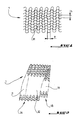
- Figure 1 shows a portion of a knitted heating web 1 used for the device of the invention.
- the sheet 1 is obtained by knitting from a resistive wire having a diameter 2r and which is covered with an insulating varnish and made to have approximately parallelepipedal meshes M with dimensions a, b or a is the reference of small side of a cell or mesh M, where b is the reference of the long side of the mesh M and where the product ab is the surface of a mesh corresponding approximately to a heating cell of the heating mat 1.
- the short side of a mesh M has dimensions ranging from 1.5 to 2.5 mm and the large side ba has dimensions ranging from 3 to 4.5 mm.
- the heating sheet 1 is made either in the form of a flat body or in the form of a sheath. Furthermore, the knitting is performed so as to give the finished heating web a certain dimensional flexibility in the direction of the length of the web and a low flexibility in the transverse direction.
- Figure 2 shows a heating web 1 made in the form of a sheath and can therefore be threaded onto a cylindrical part to be welded or be flattened and used as a strip heating web. In the latter case, the heating layer will have two layers of mesh superimposed.
- the sheet 1 is represented as a simple strip, that is to say only the layer facing the reader of the drawings.
- FIG. 2 more particularly shows a heating sheet 1 in the form of a sheath, flattened and folded once to locally increase the number of mesh layers and thus to obtain a specific overconcentration of the welding energy.
- the heating mat 1 is folded once and the two parts 1A, 1B of the sheet thus obtained are arranged partially offset relative to each other so as to obtain , as regards the number of mesh layers and the energy capacity to be supplied, a first portion of single ply 11, a portion of double ply 12 and a second portion of single ply 13.
- the double sheet portion 12 is more or less wide and more or less long.
- FIG. 3 represents a portion of a heating sheet 1 of a device of the invention, with the difference compared to that of FIG. inhomogeneous distribution of meshes on the surface considered.
- This irregular distribution of meshes is obtained manually at the time of the laying of the heating web on the surface to be melted by concentrating the mesh on a sector requiring an overconcentration of energy and spacing as much as possible in other areas.
- the stitches of the heating mat 1 are more mobile relative to each other in one direction than in the other.
- the meshes M are more mobile in the vertical direction than in the horizontal direction.
- FIG. 4 represents, by way of example, a diagram representing, for a welding cycle, the mechanical force imposed on two parts to be welded (curve A) and the temperature measured at the interface of the assembly (curve B ).
- the welding cycle includes a heating phase of about 20 seconds followed by relatively fast cooling for about 10 seconds and slower cooling for about 80 seconds. This heating cycle is offset with respect to the application cycle of the force imposed on the assembly.
- the heating period starts only about 60 seconds after the start of a cycle, this cycle start is marked by a precharge of the assembly, by the application of the maximum amount of effort during a period of about 10 seconds followed by a certain break for 50 seconds, during which time the heating period begins.
- This heating is accompanied by an additional release and a renewed effort applied to the assembly until the end of the heating period.
- the force imposed on the assembly decreases rapidly to be maintained then at a low level (of the order of 100 newtons).
Abstract
Description
La présente invention concerne un dispositif pour le soudage de deux pièces en polymère par fusion obtenue moyennant une nappe chauffante ainsi qu'un procédé de soudage de deux pièces en polymère par fusion obtenu moyennant une nappe chauffante.The present invention relates to a device for welding two pieces of polymer by fusion obtained by means of a heating sheet and a method of welding two pieces of polymer by fusion obtained by means of a heating sheet.
L'invention concerne donc le domaine de la mise en place d'un réseau de distribution d'un fluide et celui du remplacement d'un tronçon ou de plusieurs tronçons d'une canalisation ou d'un conduit en matière thermofusible d'un tel réseau.The invention thus relates to the field of setting up a distribution network of a fluid and that of the replacement of a section or several sections of a pipe or conduit made of hot melt material of such a device. network.
Les réseaux de distribution, notamment en ce qui concerne la distribution de gaz de ville ou de gaz naturel, sont actuellement déjà, et le seront de plus en plus, constitués en grande majorité de conduits formés à partir de tubes ou tuyaux en polyéthylène ou en polyamide, polybutylène, polypropylène ou polychlorure de vinyle. Pour assembler de tels tuyaux, plusieurs techniques existent. Une par exemple consiste à chauffer les embouts de deux tuyaux disposés en regard jusqu'à ce que la matière thermofusible soit suffisamment fluide pour que les deux embouts, rapprochés l'un à l'autre sous une légère pression, se fondent l'un dans l'autre et forment une jonction sensiblement étanche au gaz et avec une résistance mécanique compatible avec l'utilisation des conduits à former.Distribution networks, particularly with regard to the distribution of city gas or natural gas, are already, and will be increasingly, made up mostly of pipes formed from polyethylene pipes or pipes or polyamide, polybutylene, polypropylene or polyvinyl chloride. To assemble such pipes, several techniques exist. One example is to heat the tips of two pipes arranged facing each other until the hot melt material is sufficiently fluid so that the two endpieces, brought together under a slight pressure, merge into each other. the other and form a junction substantially gas-tight and with a mechanical strength compatible with the use of the ducts to be formed.
Selon une autre technique, on utilise une nappe chauffante réalisée à partir d'un fil résistif revêtu d'un vernis isolant. La nappe chauffante réalisée sous une forme rectangulaire ou sous la forme d'une gaine est alors conformée pour être alimentée électriquement par un automate réglable en tension ou en intensité de courant et résistant aux courts-circuits.According to another technique, using a heating mat made from a resistive wire coated with an insulating varnish. The heating mat produced in a rectangular form or in the form of a sheath is then shaped to be electrically powered by a controller adjustable in voltage or current and resistant to short circuits.
La technique de soudage au moyen d'un filet chauffant ou d'une nappe chauffante paraît être assez prometteuse, et cela aussi bien en ce qui concerne le déroulement de l'assemblage que la bonne tenue dans le temps de la jonction ainsi réalisée.The technique of welding by means of a heating net or a heating mat seems to be quite promising, and this as well with regard to the progress of the assembly that the good behavior in time of the junction thus achieved.
Le soudage de deux pièces en polymère par fusion obtenue moyennant une nappe chauffante repose sur un chauffage modéré et local de la zone à mettre en fusion d'un conduit en matière thermofusible, par exemple en polyéthylène, au moyen d'un élément chauffant électrique formant une résistance de chauffe. Ce soudage est effectué sans aucun apport de matière de rechargement. L'alimentation des conducteurs de la nappe chauffante avec une énergie électrique appropriée est assurée avantageusement, mais non exclusivement par un automate, par exemple un automate de soudage habituellement utilisé pour le soudage par électrofusion.The welding of two pieces of polymer by fusion obtained by means of a heating layer is based on a moderate and local heating of the zone to be melted of a hot melt pipe, for example polyethylene, by means of an electric heating element forming a heating resistor. This welding is done without any contribution of reloading material. Feeding the conductors of the heating mat with appropriate electrical energy is advantageously, but not exclusively, provided by an automaton, for example a welding automat usually used for electrofusion welding.
La mise en place d'une nappe chauffante ou d'un filet chauffant, lorsque l'on ne recourt pas à la présente invention, se fait essentiellement en quatre étapes, à savoir :
- injection d'une empreinte ou préforme en polyéthylène ou en un autre polymère thermofusible en une faible épaisseur, généralement de l'ordre de 0,3 mm à 0,8 mm, l'empreinte étant destinée à recevoir un fil résistif ;
- insertion et maintien du fil résistif dans l'empreinte par bobinage ;
- mise en place de connecteurs à chaque extrémité du fil bobiné ; et
- surmoulage du corps de raccord sur l'implant chauffant constitué au terme de l'étape précédente.
- injecting an imprint or preform made of polyethylene or of another thermofusible polymer in a small thickness, generally of the order of 0.3 mm to 0.8 mm, the imprint being intended to receive a resistive wire;
- inserting and maintaining the resistive wire in the cavity impression;
- placing connectors at each end of the wire wound; and
- over-molding of the coupling body on the heating implant formed at the end of the preceding step.
La réalisation de l'implant sous cette forme constitue la phase la plus délicate et la plus coûteuse compte tenu de différents facteurs pouvant perturber le procédé. De tels facteurs sont par exemple une rupture du fil au cours du bobinage, une liaison imparfaite des connecteurs au fil et la présence d'un différentiel de contraintes résiduelles plus ou moins important entre l'empreinte et le corps du raccord.The realization of the implant in this form is the most delicate and the most expensive phase considering various factors that can disturb the process. Such factors are for example a breakage of the wire during winding, an imperfect connection of the connectors to the wire and the presence of a differential residual stress more or less important between the footprint and the body of the fitting.
De plus, l'expérience a montré que la réalisation de l'implant souffre de nombreux problèmes de préparation des tubes à souder, ces problèmes étant liés principalement au grattage imparfait des surfaces à assembler.In addition, experience has shown that the realization of the implant suffers from numerous problems of preparation of the tubes to be welded, these problems being mainly related to the imperfect scraping of the surfaces to be assembled.
C'est ainsi que la technique de thermofusion par une nappe chauffante supprime le bobinage classique des raccords et amène à l'interface des caractéristiques thermiques supérieures à celles des systèmes à bobinage. Par ailleurs, la fusion par nappe chauffante permet de s'appliquer dans les cas où des pièces polymères de géométries diverses et complexes sont à souder ensemble, ce qui ne serait pas forcément possible avec le système de bobinage.Thus, the technique of thermofusion by a heating sheet eliminates the conventional winding connections and brings to the interface thermal characteristics superior to those of winding systems. Moreover, the fusion by heating sheet can be applied in cases where polymeric pieces of various geometries and complex are welded together, which would not necessarily be possible with the winding system.
Toutefois, aussi prometteur et avantageux que le soudage par fusion obtenu par une nappe chauffante puisse paraître, il n'en reste pas moins que certaines difficultés inhérentes à l'état des pièces à souder au moment du soudage n'ont pu être réglées. Ces difficultés sont principalement dues à une préparation imparfaite (grattage, nettoyage, dégraissage, ...) des pièces à souder, mais aussi à un état de dégradation plus ou moins avancé (oxydation, carbonisation,...) ou encore à des défauts d'ordre géométrique ou de rugosité importante.However, as promising and advantageous as the fusion welding obtained by a heating sheet can appear, it remains nonetheless that some difficulties inherent in the state of the parts to be welded at the time of welding could not be adjusted. These difficulties are mainly due to an imperfect preparation (scraping, cleaning, degreasing, ...) of the parts to be welded, but also to a state of more or less advanced degradation (oxidation, carbonization, ...) or to defects geometric order or significant roughness.
D'autres problèmes résultent d'une souplesse parfois insuffisante de la nappe pour une géométrie donnée des pièces, d'une fixation parfois difficile de la nappe sur la pièce à souder et de difficultés avec le maintien de la nappe dans la position déterminée jusqu'à la fusion des pièces à souder.Other problems result from a sometimes insufficient flexibility of the ply for a given geometry of the parts, a sometimes difficult fixing of the ply on the part to be welded and difficulties with the maintenance of the ply in the determined position until the fusion of the parts to be welded.
Un autre problème encore est que, dans certains cas, il serait souhaitable de pouvoir varier l'apport d'énergie de fusion d'un endroit à l'autre sur les pièces à souder. Théoriquement il serait peut-être possible d'utiliser plusieurs nappes chauffantes, chacune avec sa propre alimentation réglée selon les besoins locaux de chacune des nappes. Toutefois, une telle approche semble bien compliquée à réaliser sur un chantier, c'est-à-dire hors d'un laboratoire.Yet another problem is that in some cases it would be desirable to be able to vary the fusion energy supply from one place to another on the parts to be welded. Theoretically it may be possible to use several heating sheets, each with its own power supply adjusted to the local needs of each of the layers. However, such an approach seems very complicated to achieve on a site, that is to say outside a laboratory.
Le but de l'invention est de proposer des moyens permettant de remédier aux inconvénients énoncés ci avant.The object of the invention is to propose means for overcoming the disadvantages mentioned above.
Le but de l'invention est atteint en premier par un dispositif pour le soudage de deux pièces en polymères par fusion obtenue moyennant une nappe chauffante tricotée à partir d'un fil résistif revêtu d'un vernis isolant, la nappe chauffante étant conformée pour être alimentée électriquement par un automate réglable en tension ou en intensité de courant et résistant aux courts-circuits.The object of the invention is achieved first by a device for welding two pieces of fusion polymer obtained by means of a heating mat knitted from a resistive wire coated with an insulating varnish, the heating mat being shaped to be electrically powered by an automaton adjustable in voltage or current and short-circuit proof.
Conformément à l'invention, la nappe chauffante est obtenue à partir d'un fil résistif ayant un diamètre allant de 0,2 mm à 0,3 mm, et présente des mailles approximativement parallélépipédiques dont les dimensions vont de 1,5 x 3 mm2 à 2,5 x 4,5 mm2.According to the invention, the heating mat is obtained from a resistive wire having a diameter ranging from 0.2 mm to 0.3 mm, and has approximately parallelepipedal meshes whose dimensions range from 1.5 × 3 mm. 2 to 2.5 x 4.5 mm 2 .
Grâce aux dispositions de l'invention, il est possible d'utiliser une nappe chauffante qui est électriquement suffisamment forte pour générer des niveaux d'énergie de l'ordre de 10 à 100 joules par mm2 pour les matériaux habituels thermofusibles, et qui est en même temps suffisamment souple sur les plans mécanique et géométrique pour pouvoir s'adapter à diverses géométries des pièces à souder et, comme il sera explicité plus loin, de varier l'apport d'énergie thermique d'un endroit à l'autre des pièces à souder, et cela avec une seule nappe chauffante et une seule alimentation électrique.Thanks to the provisions of the invention, it is possible to use a heating mat which is electrically strong enough to generate energy levels of the order of 10 to 100 joules per mm 2 for the usual hot melt materials, and which is at the same time sufficiently flexible mechanically and geometrically to be able to adapt to various geometries of the parts to be welded and, as will be explained later, to vary the supply of thermal energy from one place to another of the parts to be welded, and this with a single heating pad and a single power supply.
Par ailleurs, selon une caractéristique supplémentaire de l'invention, la fixation d'une nappe chauffante sur une pièce à souder moyennant des plots en un matériau thermofusible permet un positionnement temporaire adéquat tant pour la manipulation sur chantier que pour la fabrication en usine. Plus particulièrement en usine, cette possibilité de fixation évite de devoir recourir à des moyens particuliers pour le maintien en place de la nappe chauffante et apporte donc la disparition de la robotisation de précision associée pour la mise en place de la nappe. Un autre avantage de ce mode de fixation est qu'il apporte une grande souplesse pour le positionnement de la nappe, par exemple en fixant toutes les mailles ou seulement une certaine partie des mailles, ainsi qu'une adaptation des plots au matériau des pièces à souder lorsque les pièces sont de même nature ou lorsqu'il s'agit d'un assemblage hétérogène où l'on fixe la nappe sur le matériau le plus fluide.Furthermore, according to a further feature of the invention, the fixing of a heating web on a workpiece by means of studs of a hot melt material allows a temporary positioning suitable for both site handling and for manufacturing in the factory. More particularly in the factory, this possibility of fixing avoids having to resort to special means for the maintenance of the heating ply and thus brings the disappearance of the associated precision robotization for the establishment of the ply. Another advantage of this method of attachment is that it provides great flexibility for the positioning of the web, for example by fixing all the meshes or only a certain part of the meshes, as well as an adaptation of the studs to the material of the pieces to weld when the parts are of the same nature or when it is a heterogeneous assembly where the sheet is fixed on the most fluid material.
Le but de l'invention est par ailleurs atteint avec un procédé de soudage de deux pièces en polymères par fusion obtenue moyennant une nappe chauffante tricotée à partir d'un fil résistif revêtu d'un vernis isolant, la nappe chauffante étant conformée pour être alimentée électriquement par un automate réglable en tension ou en intensité de courant et résistant aux courts-circuits, étant obtenue à partir d'un fil résistif ayant un diamètre allant de 0,2 mm à 0,3 mm, et présentant des mailles approximativement parallélépipédiques dont les dimensions vont de 1,5 x 3 mm2 à 2,5 x 4,5 mm2, le procédé comprenant au moins les étapes suivantes :
- donner à une nappe chauffante une forme se rapprochant le plus possible de celle d'au moins une des faces à fusionner des pièces à souder,
- fixer la nappe chauffante sur cette face,
- assembler les deux pièces à souder,
- effectuer le soudage.
- to give a heating sheet a shape that is as close as possible to that of at least one of the faces to be fused with parts to be welded,
- fix the heating mat on this face,
- assemble the two parts to be welded,
- perform the welding.
Selon un mode de mise en oeuvre de ce procédé, la nappe chauffante peut être fixée sur une des pièces à souder à l'aide de plots réalisés en un matériau thermofusible.According to one embodiment of this method, the heating sheet may be fixed on one of the parts to be welded using pads made of a hot-melt material.
Comme évoqué en partie déjà plus haut, la présente invention repose sur la mise en oeuvre, à l'interface de deux ou plusieurs pièces polymères à souder, d'une nappe chauffante dans le but d'assurer le soudage par électrofusion de ces pièces. Ces pièces peuvent être réalisées en la même matière, par exemple en polyéthylène, mais elles peuvent aussi être réalisées en des matières différentes, par exemple en polyéthylène et en polypropylène.As mentioned in part already above, the present invention is based on the implementation, at the interface of two or more polymer parts to be welded, a heating web in order to ensure the electrofusion welding of these parts. These parts can be made of the same material, for example polyethylene, but they can also be made of different materials, for example polyethylene and polypropylene.
Pour faciliter la lecture de la description de l'invention, il sera fait référence uniquement à un assemblage de deux pièces. Toutefois, il va sans dire que la présente invention s'applique aussi à un assemblage de trois ou davantage de pièces, par exemple lorsqu'un piquage d'un conduit par deux autres conduits doit être réalisé et lorsque ces deux conduits de piquage ne peuvent pas être assemblés auparavant.For ease of reading the description of the invention, reference will be made only to an assembly of two parts. However, it goes without saying that the present invention is also applicable to an assembly of three or more parts, for example when a connection of a duct by two other ducts must be made and when these two ducts can not be used. not be assembled before.
La nappe chauffante, qui pourrait être réalisée de différentes manières, est, pour les besoins spécifiques de l'invention, réalisée par tricotage à partir d'un fil résistif revêtu d'un vernis isolant dont le point de fusion doit être inférieur à la température de dégradation des pièces polymères à souder. Le revêtement du fil apporte une fonction d'autorégulation de la durée du chauffage des pièces à souder dans le sens que, lorsqu'une température prédéterminée de la jonction soudée à réaliser est atteinte, température qui assure une interpénétration des chaînes de molécules des faces de contact des pièces à assembler, le vernis d'isolation du fil tricoté fond et entraîne un court-circuit avec arrêt du chauffage de la nappe chauffante.The heating sheet, which could be made in different ways, is, for the specific needs of the invention, made by knitting from a resistive wire coated with an insulating varnish whose melting point must be lower than the temperature. degradation of the polymer parts to be welded. The coating of the wire provides a function of self-regulation of the duration of the heating of the parts to be welded in the sense that, when a predetermined temperature of the welded junction to be achieved is reached, the temperature which ensures an interpenetration of the chains of molecules of the faces contact of the parts to be assembled, the insulation varnish of the knitted yarn melts and causes a short circuit with stopping heating the heating web.
Par ailleurs, la nappe chauffante peut être modelée sous différentes formes, par exemple suivant un plan, sous la forme d'un cylindre ou d'une collerette, et peut ainsi être adaptée aisément à des géométries d'assemblage complexe et, le cas échéant, pour concentrer l'énergie apporté dans des zones ou en des points particuliers des pièces, par exemple un angle, une cavité ou une surépaisseur.Furthermore, the heating layer can be shaped in different forms, for example in a plane, in the form of a cylinder or a collar, and can thus easily be adapted to complex assembly geometries and, where appropriate in order to concentrate the energy supplied in particular areas or points of the parts, for example an angle, a cavity or an extra thickness.
La nappe chauffante peut être mise en forme sous différentes géométries afin de l'adapter au type de pièce à souder. En fonction de la manière dont on souhaite gérer l'énergie apportée à l'interface de soudage, la maille du tricot de la nappe chauffante peut prendre différentes dimensions. De plus, pour une taille de maille donnée, la nappe chauffante peut avantageusement être constituée d'une ou de plusieurs couches. Cet avantage peut également être utilisé pour réaliser un chauffage différencié de différentes zones thermiques des pièces à souder.The heating sheet may be shaped in different geometries to adapt to the type of workpiece to be welded. Depending on how one wishes to manage the energy supplied to the welding interface, the knit mesh of the heating web can take on different dimensions. In addition, for a given mesh size, the heating web may advantageously consist of one or more layers. This advantage can also be used to achieve a different heating of different thermal zones of the parts to be welded.
Pour fixer la nappe chauffante et pour la maintenir en place, la nappe peut être fixée à l'aide de plots de soudure en polymère fondu. Selon une version alternative, et notamment de manière à améliorer le contact entre les pièces à souder, la nappe chauffante peut avantageusement être intégrée dans l'une des pièces à souder au préalable au cycle de soudage. Cette intégration peut être réalisée par le biais d'un pré-chauffage de la nappe sous chargement extérieur adapté.To fix the heating mat and to hold it in place, the sheet may be fixed using molten polymer solder pads. According to an alternative version, and in particular so as to improve the contact between the parts to be welded, the heating web may advantageously be integrated into one of the parts to be welded before the welding cycle. This integration can be achieved by pre-heating the web under suitable external loading.
Ainsi, l'invention permet d'assurer à la fois un meilleur niveau d'énergie par unité de surface, une meilleure homogénéité de cette énergie à l'interface de soudage ainsi qu'un meilleur contrôle de la température en fonction du temps et par voie de conséquence, d'améliorer la qualité de la soudure, y compris en présence de matières résiduelles à une interface improprement préparée (grattage imparfait ou absence de nettoyage, ...) voire une interface dégradée par oxydation, pyrolyse ou carbonisation.Thus, the invention makes it possible to ensure both a better level of energy per unit area, a better homogeneity of this energy at the welding interface as well as a better control of the temperature. as a function of time and consequently, to improve the quality of the weld, including in the presence of residual materials at an improperly prepared interface (imperfect scraping or lack of cleaning, etc.) or even an interface degraded by oxidation, pyrolysis or carbonization.
Le fonctionnement de l'invention repose sur le chauffage localisé contrôlé d'au moins une interface de deux pièces en polymère, par exemple en polyéthylène pendant un temps donné, de manière à provoquer le soudage de celles-ci au terme du cycle de chauffage-refroidissement imposé par un automate du type machine à souder.The operation of the invention is based on controlled local heating of at least one interface of two pieces of polymer, for example polyethylene for a given time, so as to cause the welding thereof at the end of the heating cycle- cooling imposed by a machine type welding machine.
Dans le cas de pièces en polyéthylène, le soudage résulte d'une interpénétration moléculaire à l'interface des produits mis en contact sous l'effet de la température et du temps, imposés par la nappe chauffante.In the case of polyethylene parts, the welding results from a molecular interpenetration at the interface of the products put in contact under the effect of temperature and time, imposed by the heating layer.
Par rapport à la technique classique filamentaire, ou de bobinage, et même par rapport à la technique d'une nappe chauffante formée par une disposition en croisée d'un fil conducteur, la présente invention permet, par une meilleure gestion et une meilleure répartition de l'énergie apporté à la matière, de favoriser l'interdiffusion des macromolécules au sein de chaque microcellule approximativement délimitée par chacune des mailles de la nappe chauffante, et d'augmenter ainsi localement les possibilités d'interpénétration des matières à souder en activant une proportion plus importante de molécules diffusantes. Ainsi, le procédé de l'invention est particulièrement avantageux en présence d'états de surface imparfaits, causés, par exemple, par des cratères, une forte rugosité, des vagues, etc. ou par des matières partiellement dégradées, voire polluées.Compared to the conventional filamentary technique, or winding, and even with respect to the technique of a heating sheet formed by a cross arrangement of a conductive wire, the present invention allows, by a better management and a better distribution of the energy provided to the material, to promote the interdiffusion of the macromolecules within each microcell approximately delimited by each of the mesh of the heating web, and thus to increase locally the possibilities of interpenetration of the materials to be welded by activating a proportion more important of diffusing molecules. Thus, the method of the invention is particularly advantageous in the presence of imperfect surface conditions, caused, for example, by craters, high roughness, waves, etc. or by partially degraded or polluted materials.
Dans ce cas, la barrière à l'interdiffusion constituée par les molécules dégradées peut être surmontée par le matériau sain environnant plus en profondeur sans avoir à augmenter de manière significative le temps de soudage, comme il serait nécessaire dans le cas d'un soudage classique avec un enroulement filamentaire. En outre, le chauffage de l'interface est assuré par une nappe de résistivité donnée s'échauffant par effet joule lorsque la nappe est alimentée électriquement par une machine ou un automate adapté. Les cycles de chauffage et de refroidissement imposés à l'assemblage par l'automate peuvent être réalisés avantageusement avec des paramètres électriques tels qu'ils permettent d'utiliser l'ensemble des automates de soudage disponibles sur le marché.In this case, the interdiffusion barrier constituted by the degraded molecules can be surmounted by the surrounding sound material deeper without having to significantly increase the welding time, as would be necessary in the case of a conventional welding with a filament winding. In addition, the heating of the interface is provided by a given resistivity sheet heated by Joule effect when the sheet is electrically powered by a machine or a suitable automaton. The heating and cooling cycles imposed on assembly by the PLC can advantageously be achieved with electrical parameters such that they allow the use of all the welding machines available on the market.
Les paramètres de soudage optimaux peuvent être déterminés par approches successives au moyen d'un essai de résistance mécanique indépendant, par exemple par un essai du type pelage. Pour une qualité de soudage optimale, même en présence de matières initialement dégradées, l'énergie délivrée à l'interface doit être comprise avantageusement entre environ 10 joules par mm2 et environ 100 joules par mm2, en particulier pour le polyéthylèneThe optimum welding parameters can be determined by successive approaches by means of an independent strength test, for example by a peel-type test. For optimum welding quality, even in the presence of initially degraded materials, the energy delivered to the interface must advantageously be between about 10 joules per mm 2 and about 100 joules per mm 2 , in particular for polyethylene
Dans l'exemple d'un mode de soudage à tension imposée, le temps de chauffage de la nappe sera donc adapté en fonction de la résistance de celle-ci de manière à rester dans cette fenêtre d'énergie.In the example of an imposed voltage welding mode, the heating time of the web will therefore be adapted as a function of the resistance thereof so as to remain in this energy window.
En deçà de la valeur inférieure d'énergie par unité de surface, la qualité de la soudure n'est pas optimale, conséquence d'une interdiffusion et d'une interpénétration incomplètes des molécules au niveau de l'interface. Au-delà de la valeur supérieure d'énergie, la qualité de la soudure a tendance à diminuer lorsque la cinétique de dégradation de la matière prend le pas sur la cinétique d'interdiffusion macromoléculaire.Below the lower value of energy per unit area, the quality of the weld is not optimal, as a result of incomplete interdiffusion and interpenetration of the molecules at the interface. Beyond the higher value of energy, the quality of the solder tends to decrease when the kinetics of degradation of the material take precedence over the kinetics of macromolecular interdiffusion.
La disposition d'un filet chauffant ou d'une nappe chauffante au voisinage du plan de soudage permet d'apporter une énergie électrique par unité de surface plus importante et plus homogène en comparaison de la technique classique, par exemple par enroulement filamentaire en forme de bobine ou de nappe. L'énergie par unité de surface plus importante et mieux répartie permet d'améliorer l'interdiffusion des macromolécules à l'interface et d'améliorer ainsi la qualité de soudage y compris dans le cas d'états de surface imparfaits (par forte rugosité, vagues, cratères, etc.) et/ou de matières partiellement dégradées par oxydation, carbonisation, etc.The provision of a heating net or a heating layer in the vicinity of the welding plane makes it possible to provide a larger and more homogeneous electrical energy per unit area compared to the conventional technique, for example by filament winding in the form of coil or tablecloth. The higher and better distributed energy per unit area makes it possible to improve the interdiffusion of the macromolecules at the interface and thus to improve the quality of welding, even in the case of imperfect surface conditions (by high roughness, waves, craters, etc.) and / or partially degraded materials by oxidation, carbonization, etc.
A titre indicatif, suivant des essais réalisés en laboratoire, avec un tricot à petites mailles et un tricot à grosses mailles, avec les dimensions suivantes:
L'énergie nécessaire à la fusion de 1 mm3 de matière est de l'ordre de 190 (J/g) x 10-6 (g/mm3) soit environ
0,2 J/mm3.The energy required for the melting of 1 mm 3 of material is of the order of 190 (J / g) × 10 -6 (g / mm 3 ), ie approximately
0.2 J / mm 3 .
Dans le cas des essais de laboratoire on considère que la profondeur fondue de part et d'autre de l'interface reste inférieure à 1 mm dans les conditions optimales de soudage, soit une profondeur fondue totale de 2 mm (épaisseur totale de l'assemblage des deux éprouvettes égale à environ 4 mm).In the case of laboratory tests, the melted depth on both sides of the interface is considered to be less than 1 mm under optimal welding conditions, ie a total melted depth of 2 mm (total thickness of the assembly two test pieces equal to about 4 mm).
D'où un volume fondu par cellule de l'ordre de 2a.b (mm3) auquel il faut apporter au minimum 0,2 (J/mm3). 2a.b (mm3) soit 0,4.a.b (J) .Whence a volume melted per cell of the order of 2a.b (mm 3 ) to which must be made at least 0.2 (J / mm 3 ). 2a.b (mm 3 ) is 0.4.ab (J).
Plus généralement :
- Emin > (enthalpie de fusion) . (masse volumique) . (a.b) . (profondeur fondue) (condition 1),
- E min > (enthalpy of fusion). (Volumic mass) . (ab). (melted depth) (condition 1),
De l'expression de l'énergie : E = (U2 . t) / R (où U est la tension appliquée pendant le temps t et R est la résistance totale du tricot) et de celle de la résistance : R = (p . 1) /S (où p, 1 et S sont respectivement la résistivité, la longueur et la section du fil),
on tire : E = (U2 . t).S/(p. 1),
d'où l'énergie par unité de surface : ![]()
(où A,B est la surface chauffés totale).From the expression of energy: E = (U 2, t) / R (where U is the voltage applied during the time t and R is the total resistance of the knitting) and that of the resistance: R = (p 1) / S (where p, 1 and S are respectively the resistivity, the length and the section of the wire),
we draw: E = (U 2, t) .S / (p 1),
hence the energy per unit area: ![]()
(where A, B is the total heated area).
Ramenée à la taille de la cellule, l'énergie par unité de surface devient : ![]()
d'où:
- 10 J/mm2 < (U2 t) . [πr2] / (ρ.[2a+2b]). ([a+2r]. [b+2r]) < 100 J/m2 (condition 2),
from where:
- 10 J / mm 2 <(U 2 t). [πr 2 ] / (ρ. [2a + 2b]). ([a + 2r]. [b + 2r]) <100 J / m 2 (condition 2),
La présente invention concerne également les caractéristiques ci-après considérées isolément ou selon toute combinaison techniquement possible :
- le fil résistif de la nappe chauffante est recouvert d'un vernis ayant un point de fusion inférieur à la température de dégradation des pièces polymères à souder ;
- le fil résistif de la nappe chauffante est recouvert d'un vernis choisi selon son point de fusion ;
- la nappe chauffante est réalisée sous la forme d'un objet allongé ;
- la nappe chauffante est réalisée sous la forme d'une gaine ;
- la nappe chauffante est réalisée sous la forme d'une bande ;
- la nappe chauffante présente un pas de maille irrégulier ;
- une surconcentration ponctuelle de l'énergie de soudage est obtenue en repliant la nappe sur elle-même autant que de besoin;
- une surconcentration ponctuelle de l'énergie de soudage est obtenue en donnant à la nappe chauffante un pas de maille irrégulier.
- the resistive wire of the heating mat is coated with a varnish having a melting point lower than the degradation temperature of the polymer parts to be welded;
- the resistive wire of the heating mat is covered with a varnish chosen according to its melting point;
- the heating mat is in the form of an elongate object;
- the heating mat is in the form of a sheath;
- the heating mat is in the form of a strip;
- the heating mat has an irregular mesh pitch;
- a specific overconcentration of the welding energy is obtained by folding the sheet on itself as much as necessary;
- a specific overconcentration of the welding energy is obtained by giving the heating layer an irregular mesh pitch.
D'autres caractéristiques et avantages de la présente invention ressortiront de la description ci-après d'un mode de réalisation d'une nappe chauffante d'un dispositif de l'invention et son application à deux conduits à souder. Cette description est faite en référence aux dessins dans lesquels :
- la Figure 1 représente une partie d'une nappe chauffante d'un dispositif de l'invention,
- la Figure 2 montre la nappe de la figure 1 en position repliée,
- la Figure 3 représente une variante de la nappe chauffante de la figure 1, et
- la Figure 4 représente un diagramme d'un cycle de soudage avec mesure de la température à l'interface et de la force imposée au cours du soudage.
- FIG. 1 represents a part of a heating sheet of a device of the invention,
- FIG. 2 shows the ply of FIG. 1 in the folded position,
- FIG. 3 represents a variant of the heating sheet of FIG. 1, and
- Figure 4 shows a diagram of a welding cycle with measurement of the temperature at the interface and the force imposed during welding.
La Figure 1 représente une partie d'une nappe chauffante tricotée 1 utilisée pour le dispositif de l'invention. La nappe 1 est obtenue par tricotage à partir d'un fil résistif ayant un diamètre 2r et qui est recouvert d'un vernis isolant et confectionné de manière à présenter des mailles M approximativement parallélépipédiques avec des dimensions a, b ou a est la référence du petit côté d'une cellule ou maille M, ou b est la référence du grand côté de la maille M et où le produit a.b est la surface d'une maille correspondant approximativement à une cellule chauffante de la nappe chauffante 1. Conformément à l'invention, le petit côté d'une maille M a des dimensions allant de 1,5 à 2,5 mm et le grand côté b a des dimensions allant de 3 à 4,5 mm.Figure 1 shows a portion of a
La nappe chauffante 1 est réalisée soit sous la forme d'un corps plat, soit sous la forme d'une gaine. Par ailleurs, le tricotage est effectué de manière à donner à la nappe chauffante finie une certaine flexibilité dimensionnelle dans le sens de la longueur de la nappe et une faible flexibilité dans le sens transversal.The
La Figure 2 représente une nappe chauffante 1 réalisée sous la forme d'une gaine et pouvant donc être enfilée sur une pièce cylindrique à souder ou être aplatie et utilisée comme une nappe chauffante en bande. Dans ce dernier cas, la nappe chauffante aura donc deux couches de mailles superposées. Pour ne pas surcharger la figure 2, la nappe 1 est représentée comme une simple bande, c'est-à-dire on ne voit que la couche orientée vers le lecteur des dessins.Figure 2 shows a
La figure 2 représente plus particulièrement une nappe chauffante 1 en forme de gaine, aplatie et repliée une fois pour augmenter localement le nombre de couches de mailles et pour obtenir ainsi une surconcentration ponctuelle de l'énergie de soudage.FIG. 2 more particularly shows a
En effet, tel que cela est représenté sur la figure 2, la nappe chauffante 1 est repliée une fois et les deux parties 1A, 1B de la nappe ainsi obtenues sont disposées partiellement décalées l'une par rapport à l'autre de manière à obtenir, en ce qui concerne le nombre de couches de mailles et la capacité d'énergie à apporter, une première partie de nappe simple 11, une partie de nappe double 12 et une seconde partie de nappe simple 13. Selon la façon de décaler les deux parties 1A, 1B de la nappe 1, la partie de nappe double 12 est plus ou moins large et plus ou moins longue.Indeed, as shown in FIG. 2, the
La Figure 3 représente une partie d'une nappe chauffante 1 d'un dispositif de l'invention, avec la différence par rapport à celle de la Figure 1 d'une répartition inhomogène des mailles sur la surface considérée. Cette répartition irrégulière des mailles est obtenue manuellement au moment de la pose de la nappe chauffante sur la surface à fondre en concentrant les mailles sur un secteur demandant une surconcentration d'énergie et en espaçant au maximum les mailles dans les autres zones.3 represents a portion of a
En raison de la façon de tricotage, les mailles de la nappe chauffante 1 sont plus mobiles les unes par rapport aux autres dans un sens que dans l'autre. Sur les figures 1 à 3, les mailles M sont plus mobiles dans le sens vertical que dans le sens horizontal. Ainsi, lorsqu'il s'agit d'arranger un secteur demandant une surconcentration d'énergie, on comprime la nappe 1 dans le sens vertical et réduit par cela 1 le grand côté b1 (qui correspond au côté b de la figure 1) à un grand côté b2.Because of the way of knitting, the stitches of the
La Figure 4 représente, à titre d'exemple, un diagramme représentant, pour un cycle de soudage, l'effort mécanique imposé sur deux pièces à souder (courbe A) et la température mesurée à l'interface de l'assemblage (courbe B). Le cycle de soudage comprend une phase de chauffage d'une durée d'environ 20 secondes suivi d'un refroidissement relativement rapide pendant environ 10 secondes et d'un refroidissement plus lent pendant environ 80 secondes. Ce cycle de chauffage est décalé par rapport au cycle d'application de l'effort imposé sur l'assemblage. Comme la Figure 4 le montre, la période de chauffage commence uniquement environ 60 secondes après le début d'un cycle, ce début de cycle est marqué par une précharge de l'assemblage, par l'application de l'effort montant au maximum durant une période de 10 secondes environ suivie d'une certaine relâche pendant 50 secondes, période à laquelle la période de chauffage commence. Ce chauffage est accompagné d'une relâche supplémentaire puis d'un regain de l'effort appliqué sur l'assemblage jusqu'à la fin de la période de chauffage. Pendant le refroidissement des pièces soudées, l'effort imposé sur l'assemblage décroît rapidement pour être maintenu ensuite à un faible niveau (de l'ordre de 100 newtons).FIG. 4 represents, by way of example, a diagram representing, for a welding cycle, the mechanical force imposed on two parts to be welded (curve A) and the temperature measured at the interface of the assembly (curve B ). The welding cycle includes a heating phase of about 20 seconds followed by relatively fast cooling for about 10 seconds and slower cooling for about 80 seconds. This heating cycle is offset with respect to the application cycle of the force imposed on the assembly. As Figure 4 shows, the heating period starts only about 60 seconds after the start of a cycle, this cycle start is marked by a precharge of the assembly, by the application of the maximum amount of effort during a period of about 10 seconds followed by a certain break for 50 seconds, during which time the heating period begins. This heating is accompanied by an additional release and a renewed effort applied to the assembly until the end of the heating period. During the cooling of the welded parts, the force imposed on the assembly decreases rapidly to be maintained then at a low level (of the order of 100 newtons).
Claims (9)
caractérisé en ce que la nappe chauffante (1) est obtenue à partir d'un fil résistif ayant un diamètre allant de 0,2 mm à moins de 0,3 mm et étant recouvert d'un vernis dont le point de fusion est choisi tel que le vernis fonde à une température prédéterminée entraînant un court-circuit avec arrêt du chauffage de la nappe chauffante.Device for welding two pieces of polymer by fusion obtained by means of a heating mat (1) knitted from a resistive wire coated with an insulating varnish, the heating mat (1) being shaped to be electrically powered by an adjustable automaton in voltage or current and short-circuit resistant, the heating mat (1) having approximately parallelogram-shaped mesh sizes ranging from 1.5 to 3 mm 2 to 2.5 x 4.5 mm 2 .
characterized in that the heating mat (1) is obtained from a resistive wire having a diameter ranging from 0.2 mm to less than 0.3 mm and being covered with a varnish whose melting point is chosen such that the varnish melts at a predetermined temperature causing a short circuit with stopping heating the heating web.
Applications Claiming Priority (1)
| Application Number | Priority Date | Filing Date | Title |
|---|---|---|---|
| FR0651790A FR2901173B1 (en) | 2006-05-17 | 2006-05-17 | DEVICE AND METHOD FOR WELDING TWO MELT POLYMER PARTS |
Publications (3)
| Publication Number | Publication Date |
|---|---|
| EP1857257A2 true EP1857257A2 (en) | 2007-11-21 |
| EP1857257A3 EP1857257A3 (en) | 2008-10-22 |
| EP1857257B1 EP1857257B1 (en) | 2019-10-02 |
Family
ID=37561348
Family Applications (1)
| Application Number | Title | Priority Date | Filing Date |
|---|---|---|---|
| EP07290549.0A Active EP1857257B1 (en) | 2006-05-17 | 2007-04-30 | Device and method of fusion welding two polymer parts |
Country Status (8)
| Country | Link |
|---|---|
| US (1) | US8049146B2 (en) |
| EP (1) | EP1857257B1 (en) |
| JP (1) | JP2007307906A (en) |
| KR (1) | KR101423205B1 (en) |
| CN (1) | CN101076207B (en) |
| CA (1) | CA2588554C (en) |
| ES (1) | ES2763571T3 (en) |
| FR (1) | FR2901173B1 (en) |
Families Citing this family (4)
| Publication number | Priority date | Publication date | Assignee | Title |
|---|---|---|---|---|
| JP5560121B2 (en) * | 2010-07-07 | 2014-07-23 | 新明和工業株式会社 | Joining method of carbon fiber reinforced thermoplastic resin composite |
| FR3003349B1 (en) | 2013-03-18 | 2015-04-03 | Gdf Suez | DEVICE FOR MEASURING THE EVOLUTION OF A TEMPERATURE FIELD AND ASSOCIATED METHOD OF EVALUATING THE QUALITY OF A WELDING OPERATION |
| CN103767741B (en) * | 2013-12-19 | 2015-08-19 | 武汉佰美斯医疗科技有限公司 | The equipment of blood bag aseptic plug into method and the method use |
| CN113910506A (en) * | 2021-10-07 | 2022-01-11 | 浙江抟原复合材料有限公司 | Method for preparing large composite material mold by 3D printing technology |
Citations (3)
| Publication number | Priority date | Publication date | Assignee | Title |
|---|---|---|---|---|
| FR1473009A (en) * | 1964-07-14 | 1967-03-17 | Tecalemit | Process for welding plastic pipes preferably of small diameter and joint produced according to this process |
| EP0430762A2 (en) * | 1989-11-29 | 1991-06-05 | Gaz De France (Service National) | Process and apparatus for detecting the heat condition of a plastic element and element for joining plastic parts |
| JPH05138742A (en) * | 1991-11-21 | 1993-06-08 | Shin Etsu Polymer Co Ltd | Bonding material of building exterior material |
Family Cites Families (11)
| Publication number | Priority date | Publication date | Assignee | Title |
|---|---|---|---|---|
| US3061503A (en) * | 1956-10-29 | 1962-10-30 | Dow Chemical Co | Method of joining pipes by means of an electrically heatable sleeve |
| JPH04347094A (en) * | 1991-05-21 | 1992-12-02 | Sekisui Chem Co Ltd | Insulation resistance wire for deposited joint |
| US5500511A (en) * | 1991-10-18 | 1996-03-19 | The Boeing Company | Tailored susceptors for induction welding of thermoplastic |
| FR2690036B1 (en) * | 1992-04-10 | 1998-10-09 | Gaz De France | NET FORMING RESISTANCE, ITS APPLICATION TO WELDING OF JOINTED TUBES AND TO THE CROSS CONNECTION OF PIPES, ASSEMBLIES THUS CONSTITUTED AND ELECTRICALLY WELDABLE CONNECTION SOCKET. |
| FR2692020B1 (en) * | 1992-06-04 | 1996-01-26 | Innoge Sam | HEAT-WELDABLE CONNECTOR FOR TUBES OF PLASTIC MATERIAL AND MANUFACTURING METHOD THEREOF. |
| US5369248A (en) * | 1992-09-01 | 1994-11-29 | Gaz De France | Electro-weldable connecting piece having connection terminals and its method of manufacture |
| CH687161A5 (en) * | 1994-01-10 | 1996-09-30 | Fischer Georg Rohrleitung | Electrically weldable plastics molding. |
| US6127662A (en) * | 1995-09-20 | 2000-10-03 | Plasson Maagan Michael Industries Ltd | Electrofusion method and device |
| US7201963B2 (en) * | 2002-01-15 | 2007-04-10 | Gentex Corporation | Pre-processed workpiece having a surface deposition of absorber dye rendering the workpiece weld-enabled |
| AU2003203245A1 (en) * | 2002-01-17 | 2003-07-30 | Tatsuya Kyotani | Fusion-worked product of resin members and production method therefor and method of fusing resin members |
| JP3944559B2 (en) * | 2002-01-17 | 2007-07-11 | 直樹 鳥谷部 | Fused product of resin member, method for producing the same, and method for fusing resin member |
-
2006
- 2006-05-17 FR FR0651790A patent/FR2901173B1/en active Active
-
2007
- 2007-04-30 EP EP07290549.0A patent/EP1857257B1/en active Active
- 2007-04-30 ES ES07290549T patent/ES2763571T3/en active Active
- 2007-05-15 CA CA2588554A patent/CA2588554C/en active Active
- 2007-05-16 US US11/749,348 patent/US8049146B2/en active Active
- 2007-05-17 KR KR1020070048052A patent/KR101423205B1/en active IP Right Grant
- 2007-05-17 CN CN2007101070073A patent/CN101076207B/en active Active
- 2007-05-17 JP JP2007131533A patent/JP2007307906A/en active Pending
Patent Citations (3)
| Publication number | Priority date | Publication date | Assignee | Title |
|---|---|---|---|---|
| FR1473009A (en) * | 1964-07-14 | 1967-03-17 | Tecalemit | Process for welding plastic pipes preferably of small diameter and joint produced according to this process |
| EP0430762A2 (en) * | 1989-11-29 | 1991-06-05 | Gaz De France (Service National) | Process and apparatus for detecting the heat condition of a plastic element and element for joining plastic parts |
| JPH05138742A (en) * | 1991-11-21 | 1993-06-08 | Shin Etsu Polymer Co Ltd | Bonding material of building exterior material |
Also Published As
| Publication number | Publication date |
|---|---|
| JP2007307906A (en) | 2007-11-29 |
| US8049146B2 (en) | 2011-11-01 |
| CA2588554A1 (en) | 2007-11-17 |
| CN101076207B (en) | 2012-03-28 |
| US20070267404A1 (en) | 2007-11-22 |
| EP1857257A3 (en) | 2008-10-22 |
| CA2588554C (en) | 2014-03-25 |
| FR2901173B1 (en) | 2009-02-13 |
| KR101423205B1 (en) | 2014-07-25 |
| KR20070111393A (en) | 2007-11-21 |
| FR2901173A1 (en) | 2007-11-23 |
| ES2763571T3 (en) | 2020-05-29 |
| EP1857257B1 (en) | 2019-10-02 |
| CN101076207A (en) | 2007-11-21 |
Similar Documents
| Publication | Publication Date | Title |
|---|---|---|
| CA2031032C (en) | Improved electric resistance fitting for soldering together plastic elements | |
| CA2514771C (en) | Process for the on-site repair of a pipe or tank made of thermofusible material and device for applying the said process | |
| EP1857257B1 (en) | Device and method of fusion welding two polymer parts | |
| CA2031025A1 (en) | Electric resistance process and fitting for soldering plastic elements | |
| EP0402201A2 (en) | Wire with shaped coating, especially for making an electro-fusion insert | |
| EP0934796B1 (en) | Method of manufacturing a metallic tubular sheath wherein it is controlled that a defect-free weld has been made and apparatus for carrying out the method | |
| CA2742646A1 (en) | Method and device for making a bag | |
| FR2888772A1 (en) | Infra red radiation welding device for assembling two pieces, has infrared radiation source at preset distance from welding surfaces of pieces while heating surfaces, and masks provided between source and corresponding pieces | |
| EP0329529A1 (en) | Method for joining plastic parts together, using a cross-linking agent and an electrical heating resistor | |
| WO2022122881A1 (en) | System and method for joining high-performance thermoplastic components | |
| WO2021048288A1 (en) | Device for measuring components of a pipe prior to welding | |
| EP3089855A1 (en) | Method for injecting a tank wall comprising a localised reinforcing layer | |
| WO2022248315A1 (en) | Heating apparatus for performing localised thermal activation of a composite part | |
| EP2938981B1 (en) | Device for measuring the evolution of a temperature field and associated method for assessing the quality of a welding operation | |
| WO2021048253A1 (en) | Method for checking, and device for measuring, components of a pipe prior to welding | |
| FR2868007A1 (en) | Insert, for electric welding of joints and pipes, has a thermo-fusible insulating film substrate covering an electrical conductive circuit at least partially | |
| WO2019141946A1 (en) | Improved tool for depositing material in three dimensions by extrusion | |
| WO2022219288A1 (en) | Optical communication bundle and associated optical cable | |
| FR3035813A1 (en) | METHOD FOR MANUFACTURING CONSTRUCTIVE ELEMENTS BASED ON BAMBOO | |
| FR3095609A1 (en) | Method and installation of element reinforcement in thermoplastic polymer material | |
| OA19040A (en) | Bande composite, et procédés pour former une jonction entre deux conduites. | |
| FR3038095A1 (en) | METHOD FOR DIMENSIONING THE BOND BETWEEN A PIECE AND A SUPPORT FOR SELECTIVE POWDER BED FUSION FABRICATION |
Legal Events
| Date | Code | Title | Description |
|---|---|---|---|
| PUAI | Public reference made under article 153(3) epc to a published international application that has entered the european phase |
Free format text: ORIGINAL CODE: 0009012 |
|
| AK | Designated contracting states |
Kind code of ref document: A2 Designated state(s): AT BE BG CH CY CZ DE DK EE ES FI FR GB GR HU IE IS IT LI LT LU LV MC MT NL PL PT RO SE SI SK TR |
|
| AX | Request for extension of the european patent |
Extension state: AL BA HR MK YU |
|
| PUAL | Search report despatched |
Free format text: ORIGINAL CODE: 0009013 |
|
| AK | Designated contracting states |
Kind code of ref document: A3 Designated state(s): AT BE BG CH CY CZ DE DK EE ES FI FR GB GR HU IE IS IT LI LT LU LV MC MT NL PL PT RO SE SI SK TR |
|
| AX | Request for extension of the european patent |
Extension state: AL BA HR MK RS |
|
| RAP1 | Party data changed (applicant data changed or rights of an application transferred) |
Owner name: GDF SUEZ |
|
| 17P | Request for examination filed |
Effective date: 20090107 |
|
| AKX | Designation fees paid |
Designated state(s): AT BE BG CH CY CZ DE DK EE ES FI FR GB GR HU IE IS IT LI LT LU LV MC MT NL PL PT RO SE SI SK TR |
|
| 17Q | First examination report despatched |
Effective date: 20100414 |
|
| RAP1 | Party data changed (applicant data changed or rights of an application transferred) |
Owner name: GDF SUEZ |
|
| STAA | Information on the status of an ep patent application or granted ep patent |
Free format text: STATUS: EXAMINATION IS IN PROGRESS |
|
| GRAP | Despatch of communication of intention to grant a patent |
Free format text: ORIGINAL CODE: EPIDOSNIGR1 |
|
| STAA | Information on the status of an ep patent application or granted ep patent |
Free format text: STATUS: GRANT OF PATENT IS INTENDED |
|
| INTG | Intention to grant announced |
Effective date: 20181129 |
|
| GRAS | Grant fee paid |
Free format text: ORIGINAL CODE: EPIDOSNIGR3 |
|
| GRAA | (expected) grant |
Free format text: ORIGINAL CODE: 0009210 |
|
| STAA | Information on the status of an ep patent application or granted ep patent |
Free format text: STATUS: THE PATENT HAS BEEN GRANTED |
|
| REG | Reference to a national code |
Ref country code: DE Ref legal event code: R081 Ref document number: 602007059285 Country of ref document: DE Owner name: GRTGAZ, FR Free format text: FORMER OWNER: GAZ DE FRANCE, PARIS, FR |
|
| AK | Designated contracting states |
Kind code of ref document: B1 Designated state(s): AT BE BG CH CY CZ DE DK EE ES FI FR GB GR HU IE IS IT LI LT LU LV MC MT NL PL PT RO SE SI SK TR |
|
| RAP1 | Party data changed (applicant data changed or rights of an application transferred) |
Owner name: ENGIE |
|
| REG | Reference to a national code |
Ref country code: GB Ref legal event code: FG4D Free format text: NOT ENGLISH |
|
| REG | Reference to a national code |
Ref country code: CH Ref legal event code: EP Ref country code: AT Ref legal event code: REF Ref document number: 1185711 Country of ref document: AT Kind code of ref document: T Effective date: 20191015 |
|
| REG | Reference to a national code |
Ref country code: DE Ref legal event code: R096 Ref document number: 602007059285 Country of ref document: DE |
|
| REG | Reference to a national code |
Ref country code: IE Ref legal event code: FG4D Free format text: LANGUAGE OF EP DOCUMENT: FRENCH |
|
| RAP2 | Party data changed (patent owner data changed or rights of a patent transferred) |
Owner name: GRTGAZ |
|
| REG | Reference to a national code |
Ref country code: DE Ref legal event code: R081 Ref document number: 602007059285 Country of ref document: DE Owner name: GRTGAZ, FR Free format text: FORMER OWNER: ENGIE, COURBEVOIE, FR |
|
| REG | Reference to a national code |
Ref country code: NL Ref legal event code: MP Effective date: 20191002 |
|
| REG | Reference to a national code |
Ref country code: GB Ref legal event code: 732E Free format text: REGISTERED BETWEEN 20200123 AND 20200129 |
|
| REG | Reference to a national code |
Ref country code: LT Ref legal event code: MG4D |
|
| REG | Reference to a national code |
Ref country code: CH Ref legal event code: NV Representative=s name: VALIPAT S.A. C/O BOVARD SA NEUCHATEL, CH |
|
| REG | Reference to a national code |
Ref country code: AT Ref legal event code: MK05 Ref document number: 1185711 Country of ref document: AT Kind code of ref document: T Effective date: 20191002 |
|
| PG25 | Lapsed in a contracting state [announced via postgrant information from national office to epo] |
Ref country code: PT Free format text: LAPSE BECAUSE OF FAILURE TO SUBMIT A TRANSLATION OF THE DESCRIPTION OR TO PAY THE FEE WITHIN THE PRESCRIBED TIME-LIMIT Effective date: 20200203 Ref country code: AT Free format text: LAPSE BECAUSE OF FAILURE TO SUBMIT A TRANSLATION OF THE DESCRIPTION OR TO PAY THE FEE WITHIN THE PRESCRIBED TIME-LIMIT Effective date: 20191002 Ref country code: PL Free format text: LAPSE BECAUSE OF FAILURE TO SUBMIT A TRANSLATION OF THE DESCRIPTION OR TO PAY THE FEE WITHIN THE PRESCRIBED TIME-LIMIT Effective date: 20191002 Ref country code: NL Free format text: LAPSE BECAUSE OF FAILURE TO SUBMIT A TRANSLATION OF THE DESCRIPTION OR TO PAY THE FEE WITHIN THE PRESCRIBED TIME-LIMIT Effective date: 20191002 Ref country code: BG Free format text: LAPSE BECAUSE OF FAILURE TO SUBMIT A TRANSLATION OF THE DESCRIPTION OR TO PAY THE FEE WITHIN THE PRESCRIBED TIME-LIMIT Effective date: 20200102 Ref country code: LT Free format text: LAPSE BECAUSE OF FAILURE TO SUBMIT A TRANSLATION OF THE DESCRIPTION OR TO PAY THE FEE WITHIN THE PRESCRIBED TIME-LIMIT Effective date: 20191002 Ref country code: FI Free format text: LAPSE BECAUSE OF FAILURE TO SUBMIT A TRANSLATION OF THE DESCRIPTION OR TO PAY THE FEE WITHIN THE PRESCRIBED TIME-LIMIT Effective date: 20191002 Ref country code: GR Free format text: LAPSE BECAUSE OF FAILURE TO SUBMIT A TRANSLATION OF THE DESCRIPTION OR TO PAY THE FEE WITHIN THE PRESCRIBED TIME-LIMIT Effective date: 20200103 Ref country code: SE Free format text: LAPSE BECAUSE OF FAILURE TO SUBMIT A TRANSLATION OF THE DESCRIPTION OR TO PAY THE FEE WITHIN THE PRESCRIBED TIME-LIMIT Effective date: 20191002 Ref country code: LV Free format text: LAPSE BECAUSE OF FAILURE TO SUBMIT A TRANSLATION OF THE DESCRIPTION OR TO PAY THE FEE WITHIN THE PRESCRIBED TIME-LIMIT Effective date: 20191002 |
|
| PG25 | Lapsed in a contracting state [announced via postgrant information from national office to epo] |
Ref country code: CZ Free format text: LAPSE BECAUSE OF FAILURE TO SUBMIT A TRANSLATION OF THE DESCRIPTION OR TO PAY THE FEE WITHIN THE PRESCRIBED TIME-LIMIT Effective date: 20191002 Ref country code: IS Free format text: LAPSE BECAUSE OF FAILURE TO SUBMIT A TRANSLATION OF THE DESCRIPTION OR TO PAY THE FEE WITHIN THE PRESCRIBED TIME-LIMIT Effective date: 20200224 |
|
| REG | Reference to a national code |
Ref country code: ES Ref legal event code: FG2A Ref document number: 2763571 Country of ref document: ES Kind code of ref document: T3 Effective date: 20200529 |
|
| REG | Reference to a national code |
Ref country code: DE Ref legal event code: R097 Ref document number: 602007059285 Country of ref document: DE |
|
| PG2D | Information on lapse in contracting state deleted |
Ref country code: IS |
|
| PG25 | Lapsed in a contracting state [announced via postgrant information from national office to epo] |
Ref country code: EE Free format text: LAPSE BECAUSE OF FAILURE TO SUBMIT A TRANSLATION OF THE DESCRIPTION OR TO PAY THE FEE WITHIN THE PRESCRIBED TIME-LIMIT Effective date: 20191002 Ref country code: RO Free format text: LAPSE BECAUSE OF FAILURE TO SUBMIT A TRANSLATION OF THE DESCRIPTION OR TO PAY THE FEE WITHIN THE PRESCRIBED TIME-LIMIT Effective date: 20191002 Ref country code: DK Free format text: LAPSE BECAUSE OF FAILURE TO SUBMIT A TRANSLATION OF THE DESCRIPTION OR TO PAY THE FEE WITHIN THE PRESCRIBED TIME-LIMIT Effective date: 20191002 Ref country code: IS Free format text: LAPSE BECAUSE OF FAILURE TO SUBMIT A TRANSLATION OF THE DESCRIPTION OR TO PAY THE FEE WITHIN THE PRESCRIBED TIME-LIMIT Effective date: 20200202 |
|
| PLBE | No opposition filed within time limit |
Free format text: ORIGINAL CODE: 0009261 |
|
| STAA | Information on the status of an ep patent application or granted ep patent |
Free format text: STATUS: NO OPPOSITION FILED WITHIN TIME LIMIT |
|
| PG25 | Lapsed in a contracting state [announced via postgrant information from national office to epo] |
Ref country code: SK Free format text: LAPSE BECAUSE OF FAILURE TO SUBMIT A TRANSLATION OF THE DESCRIPTION OR TO PAY THE FEE WITHIN THE PRESCRIBED TIME-LIMIT Effective date: 20191002 |
|
| 26N | No opposition filed |
Effective date: 20200703 |
|
| PG25 | Lapsed in a contracting state [announced via postgrant information from national office to epo] |
Ref country code: SI Free format text: LAPSE BECAUSE OF FAILURE TO SUBMIT A TRANSLATION OF THE DESCRIPTION OR TO PAY THE FEE WITHIN THE PRESCRIBED TIME-LIMIT Effective date: 20191002 Ref country code: MC Free format text: LAPSE BECAUSE OF FAILURE TO SUBMIT A TRANSLATION OF THE DESCRIPTION OR TO PAY THE FEE WITHIN THE PRESCRIBED TIME-LIMIT Effective date: 20191002 |
|
| PG25 | Lapsed in a contracting state [announced via postgrant information from national office to epo] |
Ref country code: LU Free format text: LAPSE BECAUSE OF NON-PAYMENT OF DUE FEES Effective date: 20200430 |
|
| REG | Reference to a national code |
Ref country code: BE Ref legal event code: MM Effective date: 20200430 |
|
| PG25 | Lapsed in a contracting state [announced via postgrant information from national office to epo] |
Ref country code: BE Free format text: LAPSE BECAUSE OF NON-PAYMENT OF DUE FEES Effective date: 20200430 |
|
| PG25 | Lapsed in a contracting state [announced via postgrant information from national office to epo] |
Ref country code: MT Free format text: LAPSE BECAUSE OF FAILURE TO SUBMIT A TRANSLATION OF THE DESCRIPTION OR TO PAY THE FEE WITHIN THE PRESCRIBED TIME-LIMIT Effective date: 20191002 Ref country code: CY Free format text: LAPSE BECAUSE OF FAILURE TO SUBMIT A TRANSLATION OF THE DESCRIPTION OR TO PAY THE FEE WITHIN THE PRESCRIBED TIME-LIMIT Effective date: 20191002 |
|
| PGFP | Annual fee paid to national office [announced via postgrant information from national office to epo] |
Ref country code: IE Payment date: 20230322 Year of fee payment: 17 Ref country code: FR Payment date: 20230321 Year of fee payment: 17 |
|
| PGFP | Annual fee paid to national office [announced via postgrant information from national office to epo] |
Ref country code: TR Payment date: 20230328 Year of fee payment: 17 Ref country code: IT Payment date: 20230322 Year of fee payment: 17 Ref country code: GB Payment date: 20230321 Year of fee payment: 17 |
|
| PGFP | Annual fee paid to national office [announced via postgrant information from national office to epo] |
Ref country code: ES Payment date: 20230502 Year of fee payment: 17 Ref country code: DE Payment date: 20230321 Year of fee payment: 17 Ref country code: CH Payment date: 20230502 Year of fee payment: 17 |