JP3944559B2 - Fused product of resin member, method for producing the same, and method for fusing resin member - Google Patents
Fused product of resin member, method for producing the same, and method for fusing resin member Download PDFInfo
- Publication number
- JP3944559B2 JP3944559B2 JP2003008876A JP2003008876A JP3944559B2 JP 3944559 B2 JP3944559 B2 JP 3944559B2 JP 2003008876 A JP2003008876 A JP 2003008876A JP 2003008876 A JP2003008876 A JP 2003008876A JP 3944559 B2 JP3944559 B2 JP 3944559B2
- Authority
- JP
- Japan
- Prior art keywords
- resin
- pipe
- heating element
- joint
- resin member
- Prior art date
- Legal status (The legal status is an assumption and is not a legal conclusion. Google has not performed a legal analysis and makes no representation as to the accuracy of the status listed.)
- Expired - Fee Related
Links
Images


Classifications
-
- B—PERFORMING OPERATIONS; TRANSPORTING
- B29—WORKING OF PLASTICS; WORKING OF SUBSTANCES IN A PLASTIC STATE IN GENERAL
- B29C—SHAPING OR JOINING OF PLASTICS; SHAPING OF MATERIAL IN A PLASTIC STATE, NOT OTHERWISE PROVIDED FOR; AFTER-TREATMENT OF THE SHAPED PRODUCTS, e.g. REPAIRING
- B29C66/00—General aspects of processes or apparatus for joining preformed parts
- B29C66/70—General aspects of processes or apparatus for joining preformed parts characterised by the composition, physical properties or the structure of the material of the parts to be joined; Joining with non-plastics material
- B29C66/71—General aspects of processes or apparatus for joining preformed parts characterised by the composition, physical properties or the structure of the material of the parts to be joined; Joining with non-plastics material characterised by the composition of the plastics material of the parts to be joined
Description
【0001】
【発明の属する技術分野】
本発明は、樹脂部材同士(樹脂製の接合して製品となる二以上の部材)を通電加熱により融着し、接合することによって製造される樹脂加工製品(樹脂部材の融着加工製品)の製造方法、樹脂部材同士を通電加熱により融着する方法、及び樹脂部材同士を通電加熱により融着する装置等に関する。更に、少なくとも一方が樹脂製であるパイプ同士、特に樹脂製パイプと金属製パイプを接合することによって製造される樹脂加工製品の製造方法等に関する。
【0002】
【従来の技術】
従来から樹脂部材同士、特に熱可塑性樹脂製パイプ同士を融着(接合)する方法として、EF(Electric Fusion)技術が使用されている。この方法では、樹脂部材同士、特に熱可塑性樹脂製パイプ同士を融着(接合)する際に、専用継手、例えば、内部に円周(コイル)状に巻いた金属線(抵抗発熱体)が埋め込まれた継手(ソケット)を使用し、この継手内部の金属線に通電し(電流を流し)発熱させて、パイプ同士を融着(接合)させる(例えば、特許文献1参照)。
【0003】
【特許文献1】
特開平2-186193号公報
【0004】
【発明が解決しようとする課題】
しかしながら、このようなEF技術では、各国における各種規格(JIS、ISO等)に基づく樹脂製パイプに対して、専用継手(インジェクション成型品)を用いることが一般的であり、前記各種規格以外の製品に対する汎用性はない。従って、前記各種規格の製品及び前記各種規格以外の製品に対して専用継手(インジェクション成型品)以外の継手を製造して使用する場合には、継手を樹脂ブロックから切出すために、この継手に対して正確に機能する金属線を取り付ける(配設する)ことが難しい。また、樹脂部材同士のクリアランスを一定に保つことが困難で内蔵する抵抗発熱体(発熱体)によって空気量(樹脂部材同士の間隙)が多い場所の樹脂からカーボンが発生する、内蔵する抵抗発熱体(発熱体)が通電加熱中に溶融した樹脂間を移動し接触してショートする、樹脂部材と継手との隙間に空気層ができるために、この間隙での温度(環境温度)によって融着性能が左右され易いという課題があった。
【0005】
更に、前記各種規格においては管(パイプ)の製造に対して許容範囲があるために、同じ規格の管であっても正確には一定の寸法ではなく(バラツキがあり)、前記専用継手や、前記の如く樹脂ブロックから切出した継手との整合性を保ち難いため、融着性能が安定しない、EF技術は主に樹脂製のパイプを融着・接合する技術であり、平面形状(板状)や多角形等の形状に対して適用することが難しい、抵抗発熱体として使用する金属線には一般的に単一線が使用されており、金属線の長さによって通電時間、電圧等の各種設定が複雑に変わるために簡便に融着作業を行うことができない等の課題もあった。
【0006】
一方、少なくとも一方が樹脂製であるパイプ同士、特に樹脂製パイプと金属製パイプを接合することによって製造される樹脂加工製品の製造方法において、その製品のスペック、特に、それ等のパイプ同士の接合部における機械的強度(引っ張り強度等)は十分でなかった。
【0007】
このような情況下に、カーボンの発生及び内蔵する抵抗発熱体(発熱体)の通電加熱中におけるショートのない、環境の温度にも左右され難い、如何なる形状に対しても応用性のある、樹脂部材同士、及び樹脂部材同士と継手の融着方法の開発が求められる。また、少なくとも一方が樹脂製であるパイプ同士、特に樹脂製パイプと金属製パイプを接合することによって製造される樹脂加工製品の製造において、その製品のスペック、特に、それ等のパイプ同士の接合部の機械的強度が高く、かつそれ等の接合を簡便に行うことができる製造方法が求められる。
【0008】
そこで、本発明が解決しようとする課題は、樹脂部材同士を通電加熱により融着し、接合することによって製造される樹脂加工製品の製造方法として、カーボンの発生及び内蔵する抵抗発熱体(発熱体)の通電中におけるショートのない、環境の温度にも左右され難い、簡便に行うことのできる樹脂加工製品の製造方法、樹脂部材同士の融着方法及びその融着装置を開発すること、更には、樹脂部材のための継手(樹脂継手)等を開発することにある。また、少なくとも一方が樹脂製であるパイプ同士、特に樹脂製パイプと金属製パイプを接合することによって製造される樹脂加工製品の製造において、それ等の接合部の機械的強度が高く、かつそれ等の接合を簡便に行うことができる製造方法等を開発することにもある。
【0009】
【課題を解決するための手段】
本発明者等は、上記課題を解決するために鋭意検討した結果、樹脂部材同士を接合するために、前記樹脂部材同士を通電加熱により融着する際に、前記樹脂部材の接合部(接合面又はその近傍)に、抵抗発熱体として網目状又はパターン状にした金属線を配して、前記樹脂部材同士をつき合わせ、そのつき合わせた状態を保持させ、前記金属線に通電し融着するために十分な温度で発熱させて融着したときには、樹脂部材同士の接合面の強度を向上させることができ、上記課題が解決された樹脂加工製品の製造方法の供給をすることができることを見出した。
更に、本発明者等は、少なくとも一方が樹脂製であるパイプ同士を接合する場合に、先ず、一方の樹脂製パイプとの接合部に網目状又はパターン状の開口を有する抵抗発熱体を介在させた樹脂部材を、前記樹脂製パイプの端部外周につけ合わせ、そのつけ合わせた状態を保持して、前記抵抗発熱体に通電し発熱させ、前記樹脂製パイプと前記樹脂部材とを融着し、次いで、他方のパイプ(接合すべきパイプ)の端部外周にストッパーを設けるとともに、その端部内周にOリングを配し、前記接合すべきパイプの内周に配されたOリングが前記樹脂製パイプの端部外周に接するように、前記樹脂製パイプと前記他方のパイプとをつき合わせ、そのつき合わせた状態を保持して、前記樹脂製パイプに融着された樹脂部材及び前記接合すべきパイプの端部外周のストッパーをスリーブにより抱持したときには、樹脂製パイプと、接合すべきパイプとをそれ等の接合部において高い機械的強度で接合することができることを見出し、これ等の知見に基づいて本発明を完成するに到った。
【0010】
即ち、本発明の第一の視点において、樹脂部材同士を通電加熱により融着し、接合することによって製造される樹脂加工製品の製造方法であって、下記工程を含むことに特徴を有する樹脂加工製品の製造方法(以下、「本発明の樹脂加工製品の製造方法」とも称する。)を提供することができる;
a.一方の円筒状樹脂部材と他方のリング状ないし円筒状樹脂部材との間の接合部に、網目状又はパターン状の開口を有する金属線抵抗発熱体を当該接合部の少なくとも円周面状の接合面に接触するように介在させて、双方の前記樹脂部材同士をつき合わせる工程、及び
b.前記接合面における前記抵抗発熱体と圧着されていない面上に生ずる空隙において溶解された双方の樹脂部材が前記開口を充填し互いに融着するのに十分な温度になるよう前記抵抗発熱体に通電し発熱させ、前記樹脂部材同士を融着する工程。
【0011】
また、本発明の樹脂加工製品の製造方法では、前記樹脂部材同士において、これ等に使用される樹脂が、何れも熱可塑性樹脂、好ましくは何れも同一の熱可塑性樹脂、より好ましくは何れもポリエチレン樹脂である場合には、樹脂部材同士の融着をより簡便に行うことができるだけでなく、樹脂部材同士の接合面の強度をより向上させることができる。
【0012】
特に、本発明の樹脂加工製品の製造方法では、前記樹脂部材の形状が、リング状及び円筒状から選択される1以上であることが好ましい。この場合には、樹脂部材同士の融着を更に簡便に行うことができる。
【0013】
本発明の第二の視点において、樹脂部材同士を接合するために、前記樹脂部材同士を通電加熱により融着する方法であって、下記工程を含むことに特徴を有する融着方法(以下、「本発明の融着方法」とも称する。)を提供することができる;
a.前記樹脂部材の接合部に、抵抗発熱体として網目状又はパターン状にした金属線を配して、前記樹脂部材同士をつき合わせて、そのつき合わせた状態を保持する工程、及び
b.前記工程aにおいて配した前記網目状又はパターン状にした金属線に通電し融着するために十分な温度で発熱させる工程。
【0014】
また、本発明の融着方法では、前記樹脂部材同士において、これ等に使用される樹脂が、何れも熱可塑性樹脂、好ましくは何れも同一の熱可塑性樹脂、より好ましくは何れもポリエチレン樹脂である場合には、樹脂部材同士の融着をより簡便に行うことができるだけでなく、樹脂部材同士の接合面の強度をより向上させることができる。
【0015】
特に、本発明の融着方法では、前記樹脂部材の形状が、リング状及び円筒状から選択される1以上であることが好ましい。この場合には、樹脂部材同士の融着を更に簡便に行うことができる。
【0016】
本発明の第三の視点において、樹脂部材同士を接合するために、前記樹脂部材同士を通電加熱により融着する装置であって、下記手段を含むことに特徴を有する融着装置(以下、「本発明の融着装置」とも称する。)を提供することができる;
a.一方の円筒状樹脂部材と他方のリング状ないし円筒状樹脂部材との間の接合部に、抵抗発熱体として網目状又はパターン状にした網目を有する金属線を当該接合部の少なくとも円筒面状の接合面に接触するように介在させ、前記樹脂部材同士をつき合わせて保持する手段、及び
b.前記網目状又はパターン状にした金属線に前記接合面における前記金属線と圧着されていない面上に生ずる空隙において溶解された双方の樹脂部材が網目を充填し互いに融着するのに十分な温度になるよう通電し発熱させる手段。
【0017】
また、本発明の融着装置では、前記樹脂部材が、何れも熱可塑性樹脂、好ましくは何れも同一の熱可塑性樹脂、より好ましくは何れもポリエチレン樹脂である場合には、樹脂部材同士の融着をより簡便に行うことができるだけでなく、樹脂部材同士の接合面の強度をより向上させることができる。
【0018】
特に、本発明の融着装置では、前記樹脂部材の形状が、リング状及び円筒状から選択される1以上であることが好ましい。この場合には、樹脂部材同士の融着を更に簡便に行うことができる。
【0019】
本発明の第四の視点において、樹脂部材間の接合部に介在する、網目状又はパターン状の開口を有する抵抗発熱体に通電発熱させて成る、前記樹脂部材間の前記開口を通して形成された融着層を有することに特徴を有する樹脂加工製品(以下、「本発明の樹脂加工製品」とも称する。)を提供することができる。
【0020】
また、前記樹脂部材が、何れも熱可塑性樹脂、好ましくは何れも同一の熱可塑性樹脂、より好ましくは何れもポリエチレン樹脂である場合には、樹脂部材同士の接合面の強度を高めることができる。
【0021】
特に、本発明の樹脂加工製品では、その製造に際して、前記樹脂部材の形状を、リング状、円筒状又はこれ等の組み合わせにした場合には、樹脂部材同士の融着を更に簡便に行うことができるので、容易に本発明の樹脂加工製品を得ることができる。
【0022】
本発明の第五の視点において、樹脂部材と発熱体からなる、樹脂部材のための継手であって、前記発熱体は網目状又はパターン状の開口を有することに特徴を有する継手(以下、「本発明の継手」とも称する。)を提供することができる。
【0023】
更に、本発明の継手では、前記樹脂部材が、熱可塑性樹脂、好ましくはポリエチレン樹脂である場合には、樹脂部材同士との融着をより簡便に行うことができる。
【0024】
特に、本発明の継手では、前記樹脂部材の形状を、リング状又は円筒状にした場合には、樹脂部材同士の融着を更に簡便に行うことができる。
【0025】
尚、本発明の継手には、前記発熱体が、前記樹脂部材との接合面に圧着されている(樹脂部材の接合面に軽く押し付ける程度で、前記発熱体が、接合面又はその近傍にある)継手、前記発熱体が、前記樹脂部材との接合面に仮付けされている継手、更に、例えば、前記発熱体が、前記樹脂部材との接合面に仮付けされ、更に適当な樹脂(特に、樹脂の薄膜)でコーティングを施されている継手等を含めることができる。
【0026】
本発明の第六の視点において、樹脂部材同士を融着するための融着具であって、網目状又はパターン状の開口を有する発熱体であることに特徴を有する樹脂融着用の融着具(以下、「本発明の融着具」とも称する。)を提供することができる。
【0027】
本発明の第七の視点において、樹脂パイプ同士を接合するために、前記樹脂パイプ同士を通電加熱により融着する方法であって、下記工程を含むことに特徴を有する融着方法(以下、「本発明の樹脂パイプの融着方法」とも称する。)を提供することができる;
a.前記樹脂パイプの接合部に、抵抗発熱体として網目状又はパターン状にした金属線を配して、前記樹脂パイプ同士をつき合わせて、そのつき合わせた状態を保持する工程、及び
b.前記工程aにおいて配した前記網目状又はパターン状にした金属線に通電し融着するために十分な温度で発熱させる工程。
【0028】
また、本発明の樹脂パイプの融着方法では、前記樹脂パイプ同士において、これ等に使用される樹脂が、何れも熱可塑性樹脂、好ましくは何れも同一の熱可塑性樹脂、より好ましくは何れもポリエチレン樹脂である場合には、樹脂パイプ同士の融着をより簡便に行うことができるだけでなく、樹脂パイプ同士の接合面の強度をより向上させることができる。
【0029】
本発明の第八の視点において、少なくとも一方が樹脂製であるパイプ同士を接合することによって製造される樹脂加工製品の製造方法であって、下記工程を含むことに特徴を有する樹脂加工製品の製造方法(以下、「本発明のスリーブ付樹脂加工製品の製造方法」とも称する。)を提供することができる;
a.一方の樹脂製パイプとの接合部に網目状又はパターン状の開口を有する金属線抵抗発熱体を介在させた樹脂部材を、前記一方の樹脂製パイプの端部外周につけ合わせて保持する工程、
b.前記抵抗発熱体に通電し発熱させ、その前記開口を通して前記一方の樹脂製パイプと前記樹脂部材とを融着する工程、
c.前記一方の樹脂製パイプと接合すべきパイプの端部外周にストッパーを設けるとともに、その端部内周にOリングを配する工程、
d.前記接合すべきパイプの端部内周に配されたOリングが前記一方の樹脂製パイプの端部外周に接するように、前記一方の樹脂製パイプと前記接合すべきパイプとをつき合わせて保持する工程、及び
e.前記一方の樹脂製パイプに融着された樹脂部材と、前記接合すべきパイプの端部外周のストッパーとをスリーブにより抱持する工程。
【0030】
また、本発明のスリーブ付樹脂加工製品の製造方法では、前記接合すべきパイプについては特に制限は無く、樹脂製パイプや、金属製パイプ等のパイプを使用することができ、前記接合すべきパイプと前記樹脂製パイプとを簡便に接合することができるだけでなく、前記接合すべきパイプと前記樹脂製パイプとの接合部の強度をより向上させることができる。
【0031】
本発明の第九の視点において、樹脂製パイプと樹脂部材間の接合部に介在する、網目状又はパターン状の開口を有する抵抗発熱体に通電発熱させて成る樹脂製パイプと樹脂部材間の前記開口を通して形成された融着層を有する樹脂加工部材と、端部外周にストッパーが設けられた、前記樹脂製パイプと接合すべきパイプと、前記樹脂加工部材の端部外周及び前記接合すべきパイプの端部内周に接するように配されたOリングと、前記樹脂パイプに融着された樹脂部材及び前記接合すべきパイプの端部外周のストッパーを抱持するスリーブとから成ることに特徴を有する樹脂加工製品(以下、「本発明のスリーブ付樹脂加工製品」とも称する。)を提供することができる。
【0032】
また、本発明のスリーブ付樹脂加工製品では、前記接合すべきパイプについては特に制限は無く、樹脂製パイプや、金属製パイプ等のパイプを使用することができ、前記接合すべきパイプと前記樹脂製パイプとが簡便に接合され、前記接合すべきパイプと前記樹脂製パイプとの接合部の強度がより向上された樹脂加工製品を提供することができる。
【0033】
【発明の実施の形態】
以下、本発明の実施の形態について説明する。
【0034】
本発明には幾つかの形態、即ち、樹脂部材同士(樹脂製の接合して製品となる二以上の部材)を通電加熱により融着、接合して製造される樹脂加工製品の製造方法、樹脂部材同士を通電加熱により融着する方法、樹脂部材同士を通電加熱により融着する装置等が含まれる。尚、本発明の樹脂加工製品の製造方法、融着方法及び融着装置を中心に説明するが、本発明はこれ等に限定されるものではない。
(本発明の樹脂加工製品の製造方法)
本発明の樹脂加工製品の製造方法は、樹脂部材同士、特に好ましくは、リング状又は円筒状の樹脂部材同士を通電加熱により融着し、接合することによって製造される樹脂加工製品の製造方法であって、下記工程を含む樹脂加工製品の製造方法である;
a.前記樹脂部材の接合部に、網目状又はパターン状の開口を有する抵抗発熱体を介在させて、前記樹脂部材同士をつき合わせる工程、及び
b.前記抵抗発熱体に通電し発熱させ、前記樹脂部材同士を融着する工程。
【0035】
具体的に、一例として、先ず、融着(接合)すべき樹脂部材同士の大きさ、形状等に合わせて網目状又はパターン状の開口を有する抵抗発熱体を選択し、前記樹脂部材の接合部に前記抵抗発熱体を介在させる(配する)。次いで、前記抵抗発熱体を介在させた樹脂部材と融着すべき樹脂部材とをつけ合わせる。更に、介在させた前記抵抗発熱体に通電、発熱させ、前記樹脂部材同士を融着(接合)することができる。
【0036】
ここで、前記樹脂部材の接合部には、前記樹脂部材の接合面又はその近傍が含まれる。
【0037】
また、本発明において、樹脂部材の接合部に「介在させた」抵抗発熱体には、樹脂部材の接合面と圧着された状態(樹脂部材の接合面に軽く押し付ける程度で、接合面又はその近傍に抵抗発熱体がある状態)にある抵抗発熱体や、樹脂部材の接合面に仮付け(配設)された状態にある抵抗発熱体、更には、例えば、樹脂部材の接合面に抵抗発熱体を仮付けし、更に適当な樹脂(特に、薄膜の樹脂)でコーティングを施された状態にある抵抗発熱体等を含めることができる。尚、前記適当な樹脂については、使用する樹脂部材に合わせて選択され、後記説明の本発明において使用する樹脂部材用の樹脂を使用することができる。
【0038】
この方法によれば、前記抵抗発熱体の形状を自由に選択し、加工(融着すべき樹脂部材の形状に合わせて加工(曲げ等))することができるので、樹脂部材の形状は問わず、例えば、筒状(特に、リング状又は円筒状等)、板状等、何れの形状に対しても容易に融着(接合)することができる。また、このように一方の樹脂部材の形状に合わせて容易に抵抗発熱体を追従することができるために、融着しようとする樹脂部材同士(樹脂製の接合して製品となる二以上の部材)の間隙がなくなるので環境温度に左右され難くなる。更に、前記抵抗発熱体への通電により溶融した樹脂が前記網目状又はパターン状の開口を有する抵抗発熱体の開口(孔部分)に充填され、前記開口で前記抵抗発熱体への通電により溶融した一方の樹脂部材と、同様に溶融した他方の樹脂部材とが相溶(溶融混合し再構成(一体となって硬化))するので、樹脂部材同士の接合面の強度を樹脂部材自体の強度と同等にすることができる。尚、本発明の樹脂加工製品の製造方法の一例が図1に示されている(図1参照。)。
【0039】
本発明において使用する樹脂部材については、特に制限は無く、熱により溶融し再構成(一体となって硬化)する樹脂であれば使用することができるが、好ましくは熱可塑性樹脂が選択される。この熱可塑性樹脂として、例えば、ポリエチレン、ポリプロピレン等のポリオレフィン系樹脂、ポリ塩化ビニル、ポリスチレン等のビニル系樹脂、ポリメタクリル酸メチル等のアクリル樹脂、ABS樹脂等を挙げることができ、より好ましくはポリオレフィン系樹脂、更に好ましくはポリエチレン樹脂が選択される。尚、前記樹脂部材を選択する際には、融着(接合)すべき樹脂部材同士として、前記樹脂部材同士の融着を阻害しない範囲で、材質が互いに異なる樹脂、例えば、ポリエチレン樹脂とポリプロピレン樹脂を選択してもよいが、好ましくは互いに相溶性が良い樹脂部材同士、より好ましくは何れも材質が同一である樹脂部材同士が選択される。
【0040】
前記抵抗発熱体については、通電ができ、通電時に抵抗値を持つ、一般的に抵抗発熱体(発熱体)として使用される金属及びそれ等の合金を材質とするものであれば特に制限は無く、例えば、鉄若しくは鉄鋼、タングステン等の単体金属、又はこれ等を主体とするもの(線材)、鉄−クロム、ニッケル−クロム等の合金を材質とするものを挙げることができる。これ等の中では汎用性と流通性の点から鉄若しくは鉄鋼、及び鉄−クロムが好ましく選択される。
【0041】
また、本発明において使用する網目状又はパターン状の開口を有する抵抗発熱体については、抵抗発熱体全体又は全面に一様に電流が流れ、かつ均一に発熱するようなものであればよく、例えば、融着すべき樹脂部材の形状、寸法及び性状(物性)等に応じて選択すればよい。例えば、ポリエチレン製の樹脂パイプ(外径114mm(φ114))に適用する場合では、一例として、好ましくは前記抵抗発熱体の前記開口の寸法が1〜3mm程度、より好ましくは前記抵抗発熱体の前記開口の寸法が1〜3mm程度で前記抵抗発熱体に使用される金属線の太さが0.1〜0.5mm(φ0.1〜0.5)程度、更に好ましくは前記抵抗発熱体の前記開口の寸法が2mm程度で前記抵抗発熱体に使用される金属線の太さがφ0.2程度である。
【0042】
本発明において使用する網目状又はパターン状の開口を有する抵抗発熱体について、その入手方法に困難は無く、金属線を網目状又はパターン状(例えば、格子状等)に加工したものを使用することができるが、ホビー用ステンレスメッシュ等の市販の金属メッシュを使用することもできる。ここで、網目状又はパターン状の開口を有する抵抗発熱体には、例えば、完全な網目状又はパターン状の開口を有する抵抗発熱体でなくても、開口を有するものであれば、本発明において使用する網目状又はパターン状の開口を有する抵抗発熱体に含まれる。
【0043】
前記抵抗発熱体を樹脂部材に介在させる(配する)方法については特に制限はなく、例えば、ハンダゴテ等を使用して熱融着する方法等により介在させる(配設又は仮付けする)ことができ、また、前記抵抗発熱体と同一の金属材料でコの字型の綴じ金具により仮付けすることができる。更に、前記説明の如く、前記樹脂部材の成型の際に、予め前記樹脂部材中に抵抗発熱体が含まれるように成型することもできる。
【0044】
本発明において、前記樹脂部材同士をつき合わせる方法については特に制限はなく、必要により、例えば、クランプ等の治具を使用して保持する方法や、例えば、針金、ロープ、テープ等のひも状又はベルト状等の仮止めのできる材料、好ましくはこれ等のうち耐熱性のひも状又はベルト状等の材料を巻きつけて保持する方法等、一般的な固定方法を使用することができる。
【0045】
本発明において、抵抗発熱体(抵抗発熱体に使用される金属線)のショートには注意が必要であり、例えば、抵抗発熱体の端部同士が接触又は接触の恐れがある場合には、端部同士が接触しないように必要によりビニール、ゴム等の絶縁体等を介在させる。前記抵抗発熱体への通電については、例えば、網目状又はパターン状の開口を有する抵抗発熱体の端部全体に電極端子(通電プラグ)(例えば、金属クリップ、バッテリープラグ等)を設置する等をして、前記抵抗発熱体の一方の端部から他方の端部に向かって一方向に電流が流れるようにする。但し、抵抗発熱体全体又は全面に一様に電流が流れ、均一に発熱するように配慮することが好ましい。
【0046】
本発明における通電条件については、使用する(融着すべき)樹脂部材を融着するために十分な温度で前記抵抗発熱体を発熱させる条件であれば特に制限は無く、使用する樹脂部材の種類や融点、及び前記抵抗発熱体に使用される金属線の抵抗値に応じて適宜選択すれば良い。好ましくは、前記樹脂部材の接合面において前記抵抗発熱体と圧着されていない面上に生ずる空隙に、溶解されたポリエチレン樹脂の存在が確認されるまで通電する。これが確認された場合には、樹脂部材同士は極めて高い機械的強度(引っ張り強度等)で融着、接合される。例えば、ポリエチレン樹脂パイプ(外径φ114)、開口の寸法が2mmで抵抗発熱体に使用される金属線の太さφ0.2の抵抗発熱体を使用する場合では、一例として、約15V、約120〜130秒間である。
【0047】
本発明において、樹脂部材同士を融着、接合した後の前記抵抗発熱体について、その余分な部分(樹脂部材からはみ出した部分)を、適当な手段(例えば、金切りバサミ等を使用して切断する等)により容易に取り除くことができる。
【0048】
尚、本発明の樹脂加工製品の製造方法を使用して製造され、又は製造され得る樹脂加工製品も本発明に含まれる。
(本発明の融着方法)
本発明の融着方法は、樹脂部材同士を接合するために、前記樹脂部材同士を通電加熱により融着する方法であって、下記工程を含む;
a.前記樹脂部材の接合部に、抵抗発熱体として網目状又はパターン状にした金属線を配して、前記樹脂部材同士をつき合わせて、そのつき合わせた状態を保持する工程、及び
b.前記工程aにおいて配した前記網目状又はパターン状にした金属線に通電し融着するために十分な温度で発熱させる工程。
従って、前記工程a及びb以外に必要な工程を付加して本発明をより簡便に行うこともでき、このような方法も本発明に含まれる。
【0049】
先ず、前記工程aにおいて、適当な金属線を選択し、前記樹脂部材の接合部に、前記金属線を、前記説明の如く適当な方法により配して、前記樹脂部材同士をつき合わせ、更にそのつき合わせた状態を保持する。次いで、前記工程bにおいて、前記工程aにおいて配した前記金属線に、前記記載の適当な通電方法及び条件により通電し、前記樹脂部材同士を融着するために十分な温度で発熱させることで、容易に樹脂部材同士を融着、接合することができる。
【0050】
尚、前記金属線については、前記本発明の樹脂加工製品の製造方法における抵抗発熱体に関する記載が参考にされる。
【0051】
更に、前記本発明の樹脂加工製品の製造方法に記載された内容を参考にして容易に実施することができる。
【0052】
ここで、本発明において、樹脂部材の接合部に「配した」金属線には、前記同様、樹脂部材の接合面と圧着された金属線や、樹脂部材の接合面に仮付け(配設)された金属線、更には、樹脂部材中に埋設された金属線等を含めることができる。
(本発明の融着装置)
本発明の融着装置は、樹脂部材同士を接合するために、前記樹脂部材同士を通電加熱により融着する装置であって、下記手段を含むものであれば、全て本発明に含まれる;
a.前記樹脂部材同士を接合する際に、前記樹脂部材の接合部に、抵抗発熱体として網目状又はパターン状にした金属線を介在させ、前記樹脂部材同士をつき合わせて保持する手段、及び
b.前記網目状又はパターン状にした金属線に通電し融着するために十分な温度に発熱させる手段。
尚、前記本発明の樹脂加工製品の製造方法や、前記本発明の融着方法に記載された内容を参考にして容易に実施することができる。また、本発明の融着装置(融着装置例)の一例が図2〜6に示されている(図2〜6参照。)。
【0053】
ここで、樹脂部材の接合部に金属線を「介在させる」手段には、前記同様、樹脂部材と金属線とを圧着させる手段や、樹脂部材に金属線を仮付け(配設)する手段、更には、樹脂部材に金属線を埋設する手段等を含めることができる。
【0054】
前記手段aにおいて、前記樹脂部材の接合部に、前記金属線を介在させ、前記樹脂部材同士をつき合わせて保持する手段については、特に制限は無く、そのつき合わせた状態は、前記記載の如く、一般的な固定方法を使用して保持することができる。
【0055】
また、前記手段bについては、前記記載の如く、前記金属線に通電し、前記樹脂部材を融着するために十分な温度に発熱させることで、容易に樹脂部材同士を融着、接合することができる。
(本発明の樹脂加工製品)
本発明の樹脂加工製品は、樹脂部材間の接合部に介在する、網目状又はパターン状の開口を有する抵抗発熱体に通電発熱させて成る、前記樹脂部材間の前記開口を通して形成された融着層を有する樹脂加工製品であり、このような樹脂加工製品は全て本発明に含まれる。
【0056】
ここで、「融着層」とは、前記開口で前記抵抗発熱体の通電発熱により溶融した一方の樹脂部材と、同様に溶融した他方の樹脂部材とが相溶(溶融混合し再構成(一体となって硬化))して形成される層である。
【0057】
本発明の樹脂加工製品の一例が図7に示されている(図7参照。)が、図7cにおいて一例として記載されている本発明の樹脂加工製品の断面についての図は模式図であり、実際には必ずしも明確な融着層が形成されるとは限らない。
【0058】
尚、実施方法等については、前記本発明の樹脂加工製品の製造方法に記載された内容が参考にされる。
(本発明の継手)
本発明の継手は、樹脂部材と発熱体からなる、樹脂部材のための継手であって、前記発熱体は網目状又はパターン状の開口を有するものである。
【0059】
具体的に、一例として、先ず、接合すべき樹脂部材(接合して製品とすべき樹脂製の一又は二以上の部材)の大きさ、形状等に合わせて、継手として使用する樹脂部材を選択する。次いで、接合すべき樹脂部材、及びこれ等と融着(接合)させる継手(継手として使用する樹脂部材)の大きさ、形状等に合わせて網目状又はパターン状の開口を有する発熱体を選択する。前記発熱体を継手として使用する樹脂部材に配して継手とし、前記接合すべき樹脂部材と前記継手をつき合わせる。更に、つき合わせた前記継手に配した発熱体を発熱させ、前記接合すべき樹脂部材を前記継手と共に融着させることができる。
【0060】
ここで、本発明において、継手として使用する樹脂部材に「配した」発熱体には、前記樹脂部材、特にその内面と圧着された状態にある発熱体や、前記樹脂部材、特にその内面に仮付け(配設)された状態にある発熱体、更には、例えば、前記樹脂部材、特にその内面に発熱体を仮付けし、更に適当な樹脂でコーティングを施す方法、前記樹脂部材の成型の際に予め発熱体を取り付けて成型する方法等により樹脂部材に埋設された状態にある発熱体等を含めることができる。
【0061】
本発明において使用する、継手として使用する樹脂部材については、前記記載された樹脂部材と同じものを使用することができ、前記本発明の樹脂加工製品の製造方法において説明したとおりである。
【0062】
尚、前記継手として使用する樹脂部材を選択する際には、接合(融着)すべき樹脂部材の性状(物性)、材質等に合わせ、接合すべき樹脂部材との融着を阻害しない範囲で、樹脂部材を選択することができる。従って、接合すべき樹脂部材、及び継手として使用する樹脂部材として、材質が互いに異なる樹脂を選択してもよいが(例えば、前記樹脂部材にはポリエチレン樹脂を選択し、前記継手として使用する樹脂部材にはポリプロピレン樹脂を選択する等)、好ましくは互いに相溶性が良い樹脂、より好ましくは何れも材質が同一である樹脂が選択される。
【0063】
本発明の継手について、その形状は、融着すべき樹脂部材に合わせて選択すればよく、特に制限はないが、選択された継手を、例えば、二分割、三分割等、二以上に分割して用いることができる。例えば、融着すべき樹脂部材の形状が円筒状である場合には、これ等に合うリング状又は円筒状の継手を、例えば二分割にして、即ち、半円状のものを二つ使用して接合することができる。
【0064】
前記発熱体については、前記本発明の樹脂加工製品の製造方法における抵抗発熱体に関する記載を参考にすることができる。
【0065】
前記発熱体を、継手として使用する樹脂部材に配する方法については、前記本発明の樹脂加工製品の製造方法において記載された内容を参考にすることができる。尚、前記説明の如く、前記樹脂部材の成型の際に、予め前記樹脂部材中に発熱体が含まれるように成型して継手とすることもできる。
【0066】
前記発熱体について、これを通電により発熱させる場合の通電方法及びその条件等については、前記本発明の樹脂加工製品の製造方法において記載された内容を参考にすることができる。
【0067】
前記継手をつけ合わせる方法については、特に制限は無く、前記同様、一般的な固定方法を使用して保持することができる。
【0068】
本発明において、接合すべき樹脂部材を融着、接合した後の前記発熱体について、その余分な部分(継手からはみ出した部分)については前記同様、容易に取り除くことができる。
【0069】
尚、本発明の継手を使用して製造され、又は製造され得る樹脂加工製品も本発明に含まれる。
(本発明の融着具)
本発明の融着具は、樹脂部材同士を融着するための融着具であって、網目状又はパターン状の開口を有する発熱体である。尚、実施方法等については、前記記載の網目状又はパターン状の開口を有する抵抗発熱体に関する内容を参考にすることができる。
(本発明の樹脂パイプの融着方法)
前記本発明の融着方法は、接合すべき樹脂部材が好ましくは中空形状の樹脂部材、より好ましくはリング状又は円筒状の樹脂部材、更に好ましくは樹脂パイプの場合に適用される。尚、実施方法等については、前記本発明の融着方法において説明したとおりである。
【0070】
(本発明のスリーブ付樹脂加工製品の製造方法)
本発明のスリーブ付樹脂加工製品の製造方法は、少なくとも一方が樹脂製であるパイプ同士を接合することによって製造される樹脂加工製品の製造方法であって、下記工程を含むことに特徴を有する樹脂加工製品の製造方法である;
a.一方の樹脂製パイプとの接合部に網目状又はパターン状の開口を有する抵抗発熱体を介在させた樹脂部材を、前記一方の樹脂製パイプの端部外周につけ合わせて保持する工程、
b.前記抵抗発熱体に通電し発熱させ、前記一方の樹脂製パイプと前記樹脂部材とを融着する工程、
c.前記一方の樹脂製パイプと接合すべきパイプの端部外周にストッパーを設けるとともに、その端部内周にOリングを配する工程、
d.前記接合すべきパイプの端部内周に配されたOリングが前記一方の樹脂製パイプの端部外周に接するように、前記一方の樹脂製パイプと前記接合すべきパイプとをつき合わせて保持する工程、及び
e.前記一方の樹脂製パイプに融着された樹脂部材と、前記接合すべきパイプの端部外周のストッパーとをスリーブにより抱持する工程。
【0071】
具体的に、一例として、先ず、融着(接合)すべき樹脂製パイプの大きさ、形状等に合わせて網目状又はパターン状の開口を有する抵抗発熱体を選択し、前記樹脂部材の接合部に前記抵抗発熱体を介在させる(配する)。次いで、前記抵抗発熱体を介在させた樹脂部材と融着すべき樹脂パイプとをつけ合わせる。更に、介在させた前記抵抗発熱体に通電、発熱させ、前記樹脂部材と樹脂製パイプとを融着(接合)して、樹脂加工部材を得る。前記樹脂製パイプと接合すべきパイプについては、その端部外周にストッパーを設けるとともに、その端部内周にOリングを配する。
【0072】
ここで、前記「ストッパー」とは、スリーブ内面においてその内面に配された内方突出部と当接して、スリーブ内面において前記内方突出部と互いに係合するように前記樹脂部材を前記スリーブの相手パイプに対する軸方向の摺動を止めるもので、これを介して、前記樹脂部材がスリーブ内に軸方向に拘束保持され、接合すべき(典型的には挿入すべき)パイプに対しても軸方向への相対移動に対してスリーブ内に確保される。
【0073】
得られた樹脂加工部材とパイプとをつき合わせ、そのつき合わせた状態を保持して、前記樹脂部材及び前記ストッパーをスリーブで抱持することにより樹脂製パイプとこれと接合すべきパイプとを接合することができる。尚、本発明のスリーブ付樹脂加工製品の製造方法の一例が図8に示されている(図8参照。)。尚、前記抵抗発熱体を介在させた樹脂部材については、予め樹脂部材中に抵抗発熱体が含まれるようにして成型したものを使用することができる。
【0074】
本発明において使用する樹脂部材の材質については、前記説明のとおりである。
【0075】
本発明において使用する樹脂部材の形状や大きさ等の形態については、融着すべき樹脂製パイプの形態、後記ストッパーの形態、及び後記スリーブの形態に応じて選択される。例えば、樹脂製パイプの形態、後記ストッパーの形態、及び後記スリーブに合わせてリング状又は円筒状の樹脂部材を選択して、これを二分割、三分割等、二以上に分割したものを用いることができる。
【0076】
前記樹脂部材を前記樹脂製パイプにつけ合わせる位置については、特に制限は無く、前記ストッパーを設ける位置や前記スリーブの大きさ及び形状に応じて選択される。
【0077】
本発明において使用する樹脂製パイプの材質については、特に制限は無く、前記樹脂部材と熱により溶融し再構成(一体となって硬化)する樹脂であれば使用することができるが、好ましくは熱可塑性樹脂が選択される。この熱可塑性樹脂として、例えば、ポリエチレン、ポリプロピレン等のポリオレフィン系樹脂、ポリ塩化ビニル、ポリスチレン等のビニル系樹脂、ポリメタクリル酸メチル等のアクリル樹脂、ABS樹脂等を挙げることができ、より好ましくはポリオレフィン系樹脂、更に好ましくはポリエチレン樹脂が選択される。尚、前記樹脂部材を選択する際には、融着(接合)すべき樹脂パイプと樹脂部材との融着を阻害しない範囲で、材質が互いに異なる樹脂、例えば、ポリエチレン樹脂とポリプロピレン樹脂を選択してもよいが、好ましくは互いに相溶性が良い樹脂、より好ましくは何れも材質が同一である樹脂が選択される。
【0078】
前記抵抗発熱体については、前記説明のとおりである。
【0079】
尚、前記抵抗発熱体を介在させた樹脂部材には、前記樹脂部材、特にその内面と圧着された状態にある抵抗発熱体や、前記樹脂部材、特にその内面に仮付け(配設)された状態にある抵抗発熱体、更には、例えば、前記樹脂部材、特にその内面に抵抗発熱体を仮付けし、更に適当な樹脂でコーティングを施す方法、前記樹脂部材の成型の際に予め抵抗発熱体を取り付けて成型する方法等により樹脂部材に埋設された状態にある抵抗発熱体等を含めることができる。
【0080】
尚、前記抵抗発熱体の形状や大きさについては特に制限は無く、抵抗発熱体全体又は全面に一様に電流が流れ、かつ均一に発熱するようなものであればよい。具体的には、融着すべき樹脂部材の形状、寸法及び性状(物性)等に応じて選択される。例えば、ポリエチレン製の樹脂リング(外径114mm(φ114)、幅30mm)に適用する場合では、一例として、好ましくは前記抵抗発熱体の前記開口の寸法が1〜3mm程度、より好ましくは前記抵抗発熱体の前記開口の寸法が1〜3mm程度で前記抵抗発熱体に使用される金属線の太さが0.1〜0.5mm(φ0.1〜0.5)程度、更に好ましくは前記抵抗発熱体の前記開口の寸法が2mm程度で前記抵抗発熱体に使用される金属線の太さがφ0.2程度で、幅20mm程度である。
【0081】
前記樹脂製パイプとの接合部に網目状又はパターン状の開口を有する抵抗発熱体を介在させた樹脂部材を、前記樹脂製パイプの端部外周につけ合わせて保持することについては、前記記載を参考にして容易に行うことができる。
【0082】
前記樹脂製パイプと前記樹脂部材とを融着する方法については、前記説明のとおりである。
【0083】
前記樹脂製パイプと接合すべきパイプについては、特に制限は無く、ポリエチレン樹脂パイプ、塩化ビニルパイプ等の樹脂パイプや、鉄パイプ等の金属パイプ等を選択することができる。
【0084】
前記樹脂製パイプと接合すべきパイプの端部外周にストッパーを設ける場合には、特に制限は無い。例えば、前記接合すべきパイプの端部外周上に溝を作ることによってできる凸部分をストッパーとして使用することができ、また、接合すべきパイプを所望のストッパーを有するように予め成型しておくこともできる。
【0085】
また、前記ストッパーの形態については、特に制限は無く、接合すべきパイプ外周から所望の高さ又は接合すべきパイプの端部外周上に設けた溝の底面から所望の高さで、及び所望の幅で接合すべきパイプ外周を連続して取り巻くようにリング状に配したものをストッパーとしてもよいし、接合すべきパイプ外周から所望の高さ又は接合すべきパイプの端部外周上に設けた溝の底面から所望の高さ、所望の幅、及び長さを有するストッパーを数ヶ所に点在させてもよい。例えば、接合すべきパイプ外周から高さ3mm程度、若しくは接合すべきパイプの端部外周上に設けた溝の底面から高さ3mm程度(即ち、溝の深さ3mm程度)、幅3mm程度で接合すべきパイプ外周を連続して取り巻くようにリング状に配することができ、又は、接合すべきパイプ外周からの高さ3mm程度、若しくは接合すべきパイプの端部外周上に設けた溝の底面から3mm程度(即ち、溝の深さ3mm程度)、幅3mm程度、及び長さ5mm程度のものを点在させることができる。
【0086】
前記ストッパーを設ける位置については、特に制限は無く、前記樹脂部材を前記樹脂製パイプにつけ合わせる位置や前記スリーブの大きさ、形状及び機能に応じて選択される。
【0087】
前記Oリングについては、特に制限は無い。例えば、JIS規格、ARP規格、ISO規格等の規格品から、大きさや硬度を、その機能に応じて選択したり、又は所望の大きさや硬度のものを成型することができる。
【0088】
前記Oリングを前記接合すべきパイプの端部内周に配する方法については、特に困難は無い。例えば、前記接合すべきパイプの端部内周に前記Oリングに対応した溝を設け、その溝に当接するようにして配することができる。
【0089】
前記Oリングを配する位置については、特に制限は無く、つき合せる樹脂製パイプに応じて選択すればよい。
【0090】
本発明において、前記接合すべきパイプの端部内周に配されたOリングが前記樹脂製パイプの端部外周に接するように、前記樹脂製パイプと前記接合すべきパイプとをつき合わせて保持する方法については、前記樹脂部材同士をつき合わせる方法を参考にすることにより容易に実施することができる。
【0091】
前記スリーブについて、その材質、形状、及び大きさ等の形態には特に制限は無く、前記樹脂パイプに融着された樹脂部材及び前記接合すべきパイプの端部外周のストッパーを抱持することができるものであればよい。
【0092】
スリーブによる抱持方法については、特に制限は無く、当該スリーブ内面においてその内面に配された内方突出部とストッパーが当接して、スリーブ内面において前記内方突出部とストッパーとが互いに係合するように前記樹脂部材の前記スリーブの相手パイプに対する軸方向の摺動を止め、これを介して、前記樹脂部材がスリーブ内に軸方向に拘束保持され、接合すべき(典型的には挿入すべき)パイプに対しても軸方向への相対移動に対してスリーブ内に確保される方法であればよい。例えば、前記樹脂製パイプの形態、前記ストッパーの形態に合わせて選択されたリング状又は円筒状スリーブを選択して、これを二分割、三分割等、二以上に分割したものを用いて抱持することができる。尚、前記方法により抱持した後には、それぞれの分割されたスリーブを溶接により接合したり、それぞれの分割されたスリーブの外周を針金等を用いて接合・固定したり、分割されたスリーブについてその円周方向に穴をあけ、その穴に針金等を通してそれぞれを接合・固定したりすることができる。
【0093】
(本発明のスリーブ付樹脂加工製品)
本発明のスリーブ付樹脂加工製品は、樹脂製パイプと樹脂部材間の接合部に介在する、網目状又はパターン状の開口を有する抵抗発熱体に通電発熱させて成る樹脂製パイプと樹脂部材間の前記開口を通して形成された融着層を有する樹脂加工部材と、端部外周にストッパーが設けられた、前記樹脂製パイプと接合すべきパイプと、前記樹脂加工部材の端部外周及び前記接合すべきパイプの端部内周に接するように配されたOリングと、前記樹脂パイプに融着された樹脂部材及び前記接合すべきパイプの端部外周のストッパーを抱持するスリーブとから成ることに特徴を有する樹脂加工製品である。
【0094】
本発明のスリーブ付樹脂加工製品の実施方法等については、本発明のスリーブ付樹脂加工製品の製造方法に記載された内容が参考にされる。尚、本発明のスリーブ付樹脂加工製品の製造方法により製造されるスリーブ付樹脂加工製品の一例が図9に示されている(図9参照。)。
【0095】
【実施例】
以下、実施例により本発明を詳細に説明するが、この実施例により本発明は何等制限されるものではない。
【0096】
[実施例1]
(樹脂部材の融着)
外径114mm(φ114)、内径φ103、肉厚5.5mmのポリエチレン樹脂パイプを接合するために、これに対応するポリエチレン樹脂リングを半分に切り、それぞれに市販の金属メッシュ(SUS304:20メッシュ)をハンダゴテで熱融着させて取り付けた。この二つの樹脂リングを接合すべきポリエチレン樹脂パイプ同士の所定の位置(継ぎ目上)に取り付け、金属メッシュの端部を完全に覆うように通電プラグ(バッテリープラグ)を装着した。この金属メッシュに15Vの電流を130秒間流し、樹脂リングをポリエチレン樹脂パイプに融着させた。このとき、前記ポリエチレン樹脂パイプと前記樹脂リングの接合面において前記金属メッシュと圧着されていない面上に生ずる空隙に、溶解されたポリエチレン樹脂の存在が確認された。
【0097】
[実施例2]
(樹脂部材の融着)
外径114mm(φ114)、内径φ103、肉厚5.5mmのポリエチレン樹脂パイプとこれに対応するポリエチレン樹脂リングに替えて、外径φ140、内径φ127、肉厚6.5mmのポリエチレン樹脂パイプとこれに対応するポリエチレン樹脂リングを使用すること以外は、実施例1と同様の方法で樹脂リングをポリエチレン樹脂パイプに融着させた。
【0098】
[実施例3]
(樹脂加工製品の評価)
実施例1及び2で融着、接合した樹脂加工製品(試料1及び2)について、引っ張り試験による評価をした。尚、引っ張り試験は、圧縮試験機((株)東京衡機製造所製:TES-CB-10)を使用して引っ張り方向に力を転換することによって行った。その際、樹脂リングに治具を取り付け、引っ張り速度10mm/minで行った。
【0099】
【表1】
引っ張り試験による評価(単位:kN)

以上の結果、本発明品(実施例1及び2)については、何れも樹脂リングとポリエチレン樹脂パイプとの接合面に異常(樹脂リングのはがれ等)はなく、ポリエチレン樹脂パイプ自体の引っ張り強度と同等であった。従って、本発明方法は、機械的強度(引っ張り強度)に優れた樹脂加工製品を、極めて簡便に製造することができることが分かる。
【0101】
[実施例4]
(樹脂パイプと金属パイプの接合)
(1)外径φ125、内径φ114、肉厚5.5mm、幅30mmのポリエチレン樹脂リングを半分に切り、それぞれに市販の金属メッシュ(SUS304:20メッシュ)を長さ200mm、幅20mmをハンダゴテで熱融着させて取り付けた。この二つの切断された樹脂リングを外径114mm(φ114)、内径φ103、肉厚5.5mmのポリエチレン樹脂パイプ外周の所定の位置(端部)に取り付け、金属メッシュの端部を完全に覆うように通電プラグ(バッテリープラグ)を装着した。この金属メッシュに12Vの電流を180秒間流し、樹脂リングをポリエチレン樹脂パイプに融着した。このとき、前記ポリエチレン樹脂パイプと前記樹脂リングの接合面において前記金属メッシュと圧着されていない面上に生ずる空隙に、溶解されたポリエチレン樹脂の存在が確認された。
(2)外径φ133、内径φ114、肉厚9.5mmの鉄パイプ(SS400)の内周にOリング(JIS規格:P112)を取り付けるため、所定の位置にこのOリングに対応する大きさの溝を設けて、Oリングを取り付けた。更に、前記鉄パイプの端部外周の所定の位置にこの外周と同じ長さの溝(深さ3mm、幅7mm)を設けることにより、ストッパー(前記溝の底面からの高さ3mm、幅3mm)を設けた。
(3)(1)で得られたポリエチレン樹脂パイプを、その端部が(2)で得られた金属パイプの端部内周のOリングに接するようにつき合わせて保持した。
(4)前記ポリエチレン樹脂に融着された樹脂部材と、前記鉄パイプの端部外周のストッパーとを、これ等に対応した大きさ及び形状のスリーブにより抱持させた。その際、当該スリーブを二分割し、この二つのスリーブのそれぞれの内面においてその内面に配された内方突出部とストッパーが当接して、スリーブ内面において前記内方突出部とストッパーとが互いに係合するように前記樹脂部材の前記スリーブの相手パイプに対する軸方向の摺動を止め、これを介して、前記樹脂部材がスリーブ内に軸方向に拘束保持され、接合すべき(典型的には挿入すべき)パイプに対しても軸方向への相対移動に対してスリーブ内に確保されるようにした。その後、それぞれの分割された二つのスリーブを溶接により接合した。
【0102】
[実施例5]
(樹脂加工製品の水圧試験による評価)
実施例4で接合した樹脂加工製品(試料3)について、水圧試験による評価をした。尚、本試験は2回行った。
【0103】
(試験方法)
▲1▼実施例4で接合した樹脂加工製品(本発明品)の管内に対し、2kgfの水圧をかけて、この状態を1分間維持し、このときの樹脂加工製品の状態を確認した。
▲2▼その後、本発明品の管内の水圧を、2kgf毎に水圧を上げていき、前記同様にその都度その状態を1分間維持し、このときの樹脂加工製品の状態を確認した。
【0104】
(試験結果)
本発明品については、下記表2に示す水圧の値以下で、ポリエチレン樹脂−鉄接合パイプの接合部に水漏れ等の異常は無く、ポリエチレン樹脂パイプの外周においても膨張は認められなかった。
【0105】
【表2】
水圧試験による評価(単位:kgf)
[実施例6]
(樹脂加工製品の引っ張り試験による評価)
実施例4で接合した樹脂加工製品(試料3)について、引っ張り試験による評価を下記方法により行った。尚、本試験は2回行った。
【0107】
(試験方法)
▲1▼実施例4で接合した樹脂加工製品(本発明品)のポリエチレン樹脂パイプ側に固定治具を取り付けて、引っ張り試験装置(実施例3と同様の引っ張り試験装置)にセットすると共に、更にこれと前記試験装置の中間に測定計器を取り付けた。
▲2▼鉄パイプ側に固定治具を取り付け固定した。
▲3▼前記試験装置により0.5kNの引張力をかけ、この状態を1分間維持し、このときの樹脂加工製品の状態を確認した。
▲4▼その後、引張力を、0.5kN毎に上げていき、前記同様にその都度その状態を1分間維持し、このときの樹脂加工製品の状態を確認した。
【0108】
(試験結果)
本発明品については、下記表3に示すように、下記引っ張り強度の値で、ポリチレン樹脂−鉄接合パイプの接合部に異常は認められなかった。また、従来のポリエチレン樹脂−鉄接合パイプよりも引っ張り強度において極めて優れていることが分かった。
【0109】
【表3】
引っ張り試験による評価(単位:kN)
[実施例7]
(樹脂加工製品の破壊試験による評価)
実施例4で接合した樹脂加工製品(試料3)について、破壊試験による評価を下記方法により行った。
【0111】
(試験方法)
▲1▼実施例4で接合した樹脂加工製品(本発明品)のポリエチレン樹脂パイプ側に固定治具を取り付け、更にこれを破壊試験装置(実施例3と同様の引っ張り試験装置)にセットした。
▲2▼鉄パイプ側に固定治具を取り付け固定した。
▲3▼前記引っ張り機により引張力をかけ、徐々に上げていき、このときの樹脂加工製品の状態を確認した。
【0112】
(試験結果)
ポリエチレン樹脂パイプが大きく歪んだが、ポリチレン樹脂−鉄接合パイプの接合部に異常は認められず、ポリチレン樹脂−鉄接合パイプの接合部における破壊強度は35kN以上であることが分かった。
【0113】
以上の結果、本発明品(実施例4)については、ポリエチレン樹脂パイプと鉄パイプの接合部に異常(樹脂リングのはがれ等)は無く、従来のポリエチレン樹脂−鉄接合パイプよりも耐水圧、引っ張り強度及び破壊強度において極めて優れていることは明らかである。従って、本発明方法は、機械的強度(引っ張り強度等)に優れた樹脂加工製品を、極めて簡便に製造することができることが分かる。
【0114】
【発明の効果】
本発明では、前記説明のように網目状又はパターン状にした金属線(抵抗発熱体)を通電発熱させて樹脂部材同士を融着するので、カーボンの発生、内蔵する抵抗発熱体(発熱体)の通電中におけるショートもなく、環境温度による影響等も最小限にして、樹脂部材同士を簡便に融着、接合させることができる。更に、前記金属線の形状は自由に選択し、加工することができるので、樹脂部材の形状にはとらわれず、汎用性もある。従って、樹脂部材同士を接合することによって製造される樹脂加工製品、特に、樹脂部材同士を通電加熱により融着し、接合することによって製造される樹脂加工製品を簡便に製造することができる。
【0115】
環境温度による影響等も最小限で、極めて簡便に樹脂部材同士を融着(接合)することができ、機械的強度(引っ張り強度等)に優れた樹脂加工製品を提供することができる。
【0116】
更に、少なくとも一方が樹脂製であるパイプ同士、特に樹脂製パイプと金属製パイプを、それ等の接合部において高い機械的強度で接合することによって製造される樹脂加工製品を簡便に製造することができる
従って、本発明は工業的に極めて有用である。
【図面の簡単な説明】
【図1】図1は、本発明の樹脂加工製品の製造方法の一例を図示したものである。一例として、円筒状の樹脂部材(樹脂パイプ)同士と、半円状の樹脂部材(継手)を接合している。図中、aからfの順で本発明の樹脂加工製品の製造が行われる。尚、この後、同様にして前記半円状の樹脂部材と対となる樹脂部材を、前記半円状の樹脂部材を接合させた位置と反対の位置に融着させることもできる。
【図2】図2a〜2cは、本発明の融着装置の一例を図示したものである。一例として、板状の樹脂部材同士の接合部に抵抗発熱体を介在させている。
図2aは、当該融着装置を正面から見たときの図を示したものである。
図2bは、当該融着装置の平面図(当該融着装置を上から見たときの図)を示したものである。
図2cは、当該融着装置に使用される抵抗発熱体を図示したものである。
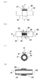
【図3】図3a及び3bは、本発明の融着装置の一例を図示したものである。一例として、円筒状の樹脂部材同士の接合部に抵抗発熱体を介在させている。
図3aは、当該融着装置を正面から見たときの図を示したものである。
図3bは、当該融着装置について、図3aにおけるA-A'方向の断面を見たときの図を示したものである。
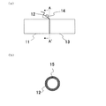
【図4】図4a〜4cは、本発明の融着装置の一例を図示したものである。一例として、円筒状の樹脂部材(樹脂パイプ)同士の接合面の近傍(継ぎ目上)に、抵抗発熱体が仮付けされた半円状の樹脂部材(継手)(リング状の樹脂部材を二分割にし、この一方に抵抗発熱体を仮付けしたもの)をつけ合わせている。
図4aは、当該融着装置を正面から見たときの図を示したものである。
図4bは、当該融着装置について、図4aにおけるB-B'方向の断面を見たときの図を示したものである。
図4cは、当該融着装置について、図4aにおけるL-L'方向の断面を見たときの図を示したものである。
【図5】図5a〜5dは、本発明の融着装置の一例を図示したものである。一例として、円筒状の樹脂部材(樹脂パイプ)同士の接合面の近傍(継ぎ目上)に、抵抗発熱体が仮付けされたリング状の樹脂部材(継手)をつけ合わせている。
図5aは、当該融着装置を正面から見たときの図を示したものである。
図5bは、当該融着装置を上から見たときの図を示したものである。
図5cは、当該融着装置について、図5aにおけるC-C'方向の断面を見たときの図を示したものである。
図5dは、当該融着装置について、図5bにおけるM-M'方向の断面を見たときの図を示したものである。
【図6】図6a〜6cは、本発明の融着装置の一例を図示したものである。一例として、円筒状の樹脂部材(樹脂パイプ)同士の接合面の近傍(継ぎ目上)に、抵抗発熱体が仮付けされた半円状の樹脂部材(継手)をつけ合わせている。
図6aは、当該融着装置を正面から見たときの図を示したものである。
図6bは、当該融着装置を上から見たときの図を示したものである。
図6cは、当該融着装置について、図6aにおけるD-D'方向の断面を見たときの図を示したものである。
【図7】図7a〜7cは、本発明の樹脂加工製品の一例を図示したものである。
図7aは、本発明の樹脂加工製品の一例として、円筒状の樹脂部材(樹脂パイプ)同士とリング状の樹脂部材(継手)を接合したものを図示したものである。
図7bは、当該樹脂加工製品を正面から見たときの図を示したものである。
図7cは、当該樹脂加工製品について、図7bにおけるE-E'方向の断面を見たときの図を示したものである。樹脂部材同士(樹脂部材1及び2)と継手(樹脂部材3)との接合部に、抵抗発熱体の通電発熱により樹脂部材同士と継手とが溶融、融着(溶融混合し再構成(一体となって硬化))して形成された融着層がある。
【図8】図8は、本発明のスリーブ付樹脂加工製品の製造方法の一例を図示したものである。一例として、樹脂製パイプと、これと接合すべきパイプとがスリーブを用いて接合されている。図中、aからfの順で本発明のスリーブ付樹脂加工製品の製造が行われる。
【図9】図9a〜9dは、本発明のスリーブ付樹脂加工製品の一例を図示したものである。一例として、ポリエチレン樹脂パイプに融着されたポリエチレン樹脂部材と鉄パイプ外周のストッパーが、スリーブにより抱持されることによりポリエチレン樹脂パイプと鉄パイプが接合されている。
図9aは、当該スリーブ付樹脂加工製品を正面から見たときの図を示したものである。
図9bは、当該スリーブ付樹脂加工製品を上から見たときの図を示したものである。
図9cは、当該スリーブ付樹脂加工製品について、図9bにおけるF-F'方向の断面を見たときの図を示したものである。
図9dは、当該スリーブ付樹脂加工製品について、図9cにおけるG-G'方向の断面を見たときの図を示したものである。
【符号の説明】
1.樹脂部材1(継手)
2.抵抗発熱体(金属メッシュ)
3.樹脂部材2
4.樹脂部材3
5.通電プラグ(電極端子)
6.余分な抵抗発熱体
7.樹脂部材1
8.抵抗発熱体(金属メッシュ)
9.樹脂部材2
10.通電プラグ(電極端子)
11.樹脂部材1
12.抵抗発熱体(金属メッシュ)
13.樹脂部材2
14.通電プラグ(電極端子)
15.絶縁体
16.樹脂部材1
17.抵抗発熱体(金属メッシュ)
18.樹脂部材2
19.樹脂部材3(継手)
20.通電プラグ(電極端子)
21.つき合わせた樹脂部材(樹脂部材1及び2)
22.樹脂部材1
23.抵抗発熱体(金属メッシュ)
24.樹脂部材2
25.樹脂部材3(継手)
26.通電プラグ(電極端子)
27.つき合わせた樹脂部材(樹脂部材1及び2)
28.絶縁体
29.樹脂部材1
30.抵抗発熱体(金属メッシュ)
31.樹脂部材2
32.樹脂部材3(継手)
33.通電プラグ(電極端子)
34.つき合わせた樹脂部材(樹脂部材1及び2)
35.樹脂部材1
36.樹脂部材2
37.樹脂部材3(継手)
38.融着層
39.接合した樹脂部材(樹脂部材1及び2)
40.樹脂部材
41.抵抗発熱体
42.樹脂製パイプ
43.樹脂製パイプと接合すべきパイプ
44.ストッパー
45.スリーブ
46.ポリエチレン樹脂パイプ
47.ポリエチレン樹脂部材
48.鉄パイプ
49.Oリング
50.スリーブ
51.ストッパー
52.抵抗発熱体[0001]
BACKGROUND OF THE INVENTION
The present invention relates to a resin processed product (fusing processed product of a resin member) manufactured by fusing and bonding resin members (two or more members that are made into a product by joining them) by energization heating. The present invention relates to a manufacturing method, a method of fusing resin members by electric heating, and an apparatus for fusing resin members by electric heating. Furthermore, the present invention relates to a method of manufacturing a resin processed product manufactured by joining pipes, at least one of which is made of resin, particularly a resin pipe and a metal pipe.
[0002]
[Prior art]
Conventionally, EF (Electric Fusion) technology has been used as a method for fusing (joining) resin members, particularly thermoplastic resin pipes. In this method, when fusing (joining) resin members, particularly thermoplastic resin pipes, a dedicated joint, for example, a metal wire (resistance heating element) wound in a circumferential shape (coil) inside is embedded. Using the joint (socket) thus prepared, the metal wire inside the joint is energized (current is passed) to generate heat, and the pipes are fused (joined) (for example, see Patent Document 1).
[0003]
[Patent Document 1]
Japanese Patent Laid-Open No. 2-186193
[0004]
[Problems to be solved by the invention]
However, in such EF technology, it is common to use dedicated joints (injection molded products) for resin pipes based on various standards (JIS, ISO, etc.) in each country. There is no versatility. Therefore, when a joint other than a dedicated joint (injection molded product) is manufactured and used for products of the various standards and products other than the various standards, the joint is cut out from the resin block. On the other hand, it is difficult to attach (arrange) a metal wire that functions correctly. Also, it is difficult to keep the clearance between the resin members constant, and the built-in resistance heating element (heating element) generates carbon from the resin in a place where the amount of air (gap between the resin members) is large. Because the (heating element) moves between the molten resin during electrical heating, contacts and shorts, and an air layer is formed in the gap between the resin member and the joint, the fusing performance depends on the temperature (environment temperature) in this gap. There is a problem that is easily affected.
[0005]
Furthermore, in the various standards, since there is an allowable range for the manufacture of pipes (pipes), even the pipes of the same standard are not exactly constant dimensions (there is variation), the dedicated joint, As mentioned above, it is difficult to maintain consistency with the joint cut out from the resin block, so the fusion performance is not stable. The EF technique is a technique for fusing and joining mainly resin pipes, and has a planar shape (plate shape). In general, a single wire is used for the metal wire used as a resistance heating element, which is difficult to apply to shapes such as polygons, etc., and various settings such as energization time and voltage depending on the length of the metal wire However, since there is a complicated change, there is a problem that the fusion work cannot be easily performed.
[0006]
On the other hand, in a method of manufacturing a resin processed product manufactured by joining at least one of resin pipes, particularly a resin pipe and a metal pipe, the specifications of the product, in particular, joining of the pipes. The mechanical strength (tensile strength, etc.) at the part was not sufficient.
[0007]
Under such circumstances, there is no short circuit during the generation of carbon and current heating of the built-in resistance heating element (heating element), it is hardly affected by the temperature of the environment, and it is applicable to any shape. Development of a method for fusing members and between resin members and joints is required. Moreover, in the manufacture of resin processed products manufactured by joining pipes, at least one of which is made of resin, in particular, resin pipes and metal pipes, the specifications of the products, particularly the joints between these pipes There is a need for a production method that has a high mechanical strength and that can be simply joined.
[0008]
Therefore, the problem to be solved by the present invention is to generate carbon and generate a resistance heating element (heating element) as a manufacturing method of a resin processed product manufactured by fusing and joining resin members by electric heating. ) Development of a method for manufacturing a resin processed product that is not affected by the temperature of the environment without being short-circuited during energization and can be easily performed, a method for fusing resin members to each other, and a fusing device therefor, The purpose is to develop joints (resin joints) for resin members. Moreover, in the manufacture of resin processed products manufactured by joining pipes, at least one of which is made of resin, in particular, resin pipes and metal pipes, the mechanical strength of these joints is high, and the like There is also the development of a manufacturing method and the like that can be easily joined.
[0009]
[Means for Solving the Problems]
As a result of intensive studies to solve the above-mentioned problems, the present inventors have found that when the resin members are fused to each other by energization heating in order to join the resin members, (Or in the vicinity thereof), a metal wire having a mesh shape or a pattern shape is arranged as a resistance heating element, the resin members are brought into contact with each other, the attached state is maintained, and the metal wire is energized and fused. For this reason, it is found that when the heat is generated at a sufficient temperature and fused, the strength of the joint surface between the resin members can be improved, and a method for producing a resin processed product in which the above problems are solved can be supplied. It was.
Furthermore, when joining the pipes at least one of which is made of resin, the present inventors first put a resistance heating element having a mesh-like or pattern-like opening at the joint with one of the resin pipes. The resin member is attached to the outer periphery of the end portion of the resin pipe, and the attached state is maintained. The resistance heating element is energized to generate heat, and the resin pipe and the resin member are fused. Next, a stopper is provided on the outer periphery of the other pipe (the pipe to be joined), an O-ring is arranged on the inner circumference of the end, and the O-ring arranged on the inner circumference of the pipe to be joined is made of the resin. The resin pipe and the other pipe are brought together so as to be in contact with the outer periphery of the end of the pipe, and the joined state is maintained, and the resin member fused to the resin pipe and the joint should be joined pipe When holding the stopper on the outer periphery of the end with the sleeve, we found that the resin pipe and the pipe to be joined can be joined with high mechanical strength at their joints, and based on these findings The present invention has been completed.
[0010]
That is, in the first aspect of the present invention, a resin processed product manufacturing method is produced by fusing and joining resin members to each other by energization heating, the resin processing having the following steps A method for producing a product (hereinafter also referred to as “a method for producing a resin-processed product of the present invention”) can be provided;
a. Between one cylindrical resin member and the other ring-shaped or cylindrical resin member Has a mesh or pattern opening at the joint The metal wire resistance heating element is interposed so as to be in contact with at least the circumferential surface of the joint. Attaching the resin members together, and
b. Both the resin members dissolved in the gap formed on the non-compressed surface with the resistance heating element on the joint surface are at a temperature sufficient to fill the opening and fuse together. Energizing the resistance heating element to generate heat and fusing the resin members together;
[0011]
In the method for producing a processed resin product of the present invention, the resin used for the resin members is a thermoplastic resin, preferably the same thermoplastic resin, more preferably all polyethylene. In the case of resin, not only can the resin members be fused more easily, but also the strength of the joint surface between the resin members can be further improved.
[0012]
In particular, in the method for producing a processed resin product of the present invention, it is preferable that the shape of the resin member is one or more selected from a ring shape and a cylindrical shape. In this case, the resin members can be more easily fused.
[0013]
In the second aspect of the present invention, in order to join resin members to each other, the resin members are fused to each other by energization heating, and includes the following steps. Also referred to as the "fusion method of the present invention");
a. Arranging a metal wire in a mesh shape or a pattern as a resistance heating element at a joint portion of the resin member, bringing the resin members together, and maintaining the attached state; and
b. A step of generating heat at a temperature sufficient to energize and fuse the mesh or patterned metal wire disposed in step a.
[0014]
In the fusion method of the present invention, among the resin members, the resins used for them are all thermoplastic resins, preferably the same thermoplastic resin, more preferably all polyethylene resins. In this case, not only can the resin members be fused more easily, but also the strength of the joint surface between the resin members can be further improved.
[0015]
In particular, in the fusion method of the present invention, it is preferable that the shape of the resin member is one or more selected from a ring shape and a cylindrical shape. In this case, the resin members can be more easily fused.
[0016]
In a third aspect of the present invention, in order to join resin members together, the resin members are fused together by energization heating, and include a fusion device (hereinafter, “ Also referred to as a "fusion apparatus of the present invention");
a. One cylindrical resin member and the other ring or cylinder Resin member Between In the joint portion, a mesh or pattern was formed as a resistance heating element. Have a mesh Metal wire To contact at least the cylindrical surface of the joint Means for interposing and holding the resin members together, and
b. To the mesh-like or patterned metal wire Both resin members dissolved in the gap formed on the non-crimped surface with the metal wire at the joining surface are at a temperature sufficient to fill the mesh and fuse together. Means to energize and generate heat.
[0017]
In the fusion apparatus of the present invention, when the resin members are all thermoplastic resins, preferably the same thermoplastic resin, more preferably polyethylene resins, the resin members are fused. Can be performed more simply, and the strength of the joint surface between the resin members can be further improved.
[0018]
In particular, in the fusion apparatus of the present invention, it is preferable that the shape of the resin member is one or more selected from a ring shape and a cylindrical shape. In this case, the resin members can be more easily fused.
[0019]
In a fourth aspect of the present invention, a fusion formed through the openings between the resin members, which is formed by energizing and heating a resistance heating element having a mesh-like or pattern-like opening, which is interposed at a joint between the resin members. It is possible to provide a resin processed product (hereinafter also referred to as “the resin processed product of the present invention”) characterized by having an adhesive layer.
[0020]
Further, when the resin members are all thermoplastic resins, preferably the same thermoplastic resin, more preferably polyethylene resins, the strength of the joint surface between the resin members can be increased.
[0021]
In particular, in the resin processed product of the present invention, when the shape of the resin member is a ring shape, a cylindrical shape, or a combination thereof, the resin members can be more easily fused together. Therefore, the resin processed product of the present invention can be easily obtained.
[0022]
According to a fifth aspect of the present invention, there is provided a joint for a resin member comprising a resin member and a heating element, wherein the heating element has a mesh-like or pattern-like opening (hereinafter referred to as “ Also referred to as “the joint of the present invention”).
[0023]
Furthermore, in the joint according to the present invention, when the resin member is a thermoplastic resin, preferably a polyethylene resin, the resin member can be more easily fused.
[0024]
In particular, in the joint according to the present invention, when the shape of the resin member is a ring shape or a cylindrical shape, the resin members can be more easily fused.
[0025]
In the joint of the present invention, the heating element is pressure-bonded to the bonding surface with the resin member (the heating element is at or near the bonding surface to the extent that it is lightly pressed against the bonding surface of the resin member. ) A joint, a joint in which the heating element is temporarily attached to a joint surface with the resin member, and further, for example, the heating element is temporarily attached to a joint surface with the resin member, and further suitable resin (especially Fittings coated with resin thin film) etc Can be included.
[0026]
According to a sixth aspect of the present invention, there is provided a fusion tool for fusing resin members together, wherein the fusion tool is a heating element having a mesh-like or pattern-like opening. (Hereinafter also referred to as “the fusion tool of the present invention”).
[0027]
In the seventh aspect of the present invention, in order to join the resin pipes, a method of fusing the resin pipes by electrical heating, the method comprising the following steps: Also referred to as “fusing method of resin pipe of the present invention”);
a. Arranging a metal wire in a mesh or pattern as a resistance heating element at the joint of the resin pipe, bringing the resin pipes together, and maintaining the attached state; and
b. A step of generating heat at a temperature sufficient to energize and fuse the mesh or patterned metal wire disposed in step a.
[0028]
In the method for fusing resin pipes of the present invention, among the resin pipes, the resins used for these are all thermoplastic resins, preferably the same thermoplastic resin, more preferably all polyethylene. In the case of resin, not only can the resin pipes be fused more easily, but also the strength of the joint surface between the resin pipes can be further improved.
[0029]
In the eighth aspect of the present invention, a method for producing a resin processed product manufactured by joining pipes, at least one of which is made of resin, including the following steps: A method (hereinafter also referred to as “a method for producing a resin-processed product with a sleeve of the present invention”) can be provided;
a. Has a mesh or pattern opening at the joint with one resin pipe Metal wire A process of holding and holding a resin member with a resistance heating element attached to the outer periphery of the end of the one resin pipe;
b. Energize the resistance heating element to generate heat, Through that said opening Fusing the one resin pipe and the resin member;
c. A step of providing a stopper on the outer periphery of the end of the pipe to be joined to the one resin pipe, and arranging an O-ring on the inner periphery of the end;
d. The one resin pipe and the pipe to be joined are held together so that an O-ring arranged on the inner circumference of the end of the pipe to be joined contacts the outer circumference of the end of the one resin pipe. Process, and
e. A step of holding a resin member fused to the one resin pipe and a stopper on an outer periphery of an end of the pipe to be joined by a sleeve.
[0030]
In the method for manufacturing a resin processed product with a sleeve according to the present invention, the pipe to be joined is not particularly limited, and a pipe such as a resin pipe or a metal pipe can be used. And the resin pipe can be simply joined together, and the strength of the joint between the pipe to be joined and the resin pipe can be further improved.
[0031]
In the ninth aspect of the present invention, between the resin pipe and the resin member formed by energizing and heating the resistance heating element having a mesh-like or pattern-like opening, which is interposed at the joint between the resin pipe and the resin member. A resin processed member having a fusion layer formed through an opening, a pipe to be joined to the resin pipe provided with a stopper on the outer periphery of the end, an outer periphery of the end of the resin processed member, and a pipe to be joined It is characterized by comprising an O-ring arranged so as to be in contact with the inner periphery of the end of the resin, a resin member fused to the resin pipe, and a sleeve for holding a stopper on the outer periphery of the end of the pipe to be joined. A resin processed product (hereinafter also referred to as “the resin processed product with a sleeve of the present invention”) can be provided.
[0032]
In the resin processed product with a sleeve of the present invention, the pipe to be joined is not particularly limited, and a pipe such as a resin pipe or a metal pipe can be used. The pipe to be joined and the resin It is possible to provide a resin processed product in which the strength of the joint portion between the pipe to be joined and the resin pipe is further improved.
[0033]
DETAILED DESCRIPTION OF THE INVENTION
Embodiments of the present invention will be described below.
[0034]
The present invention has several forms, that is, a method for producing a resin processed product, which is produced by fusing and joining resin members (two or more members that are made of resin to form a product) by energization heating, and resin A method for fusing members by current heating, a device for fusing resin members by current heating, and the like are included. In addition, although demonstrated centering on the manufacturing method of the resin processed product of this invention, a fusion | melting method, and a fusion | melting apparatus, this invention is not limited to these.
(Manufacturing method of the resin processed product of the present invention)
The method for producing a resin processed product of the present invention is a method for producing a resin processed product produced by fusing and joining resin members, particularly preferably, ring-shaped or cylindrical resin members by electrical heating. A method for producing a resin processed product including the following steps;
a. Interposing a resistance heating element having a mesh-like or pattern-like opening in the joint part of the resin member, and attaching the resin members together; and
b. Energizing the resistance heating element to generate heat and fusing the resin members together;
[0035]
Specifically, as an example, first, a resistance heating element having a mesh-like or pattern-like opening is selected in accordance with the size, shape, etc. of the resin members to be fused (joined), and the joint portion of the resin member The resistance heating element is interposed in (arranged). Next, the resin member having the resistance heating element interposed therebetween and the resin member to be fused are attached together. Further, the resin member can be fused (bonded) by energizing and generating heat to the interposed resistance heating element.
[0036]
Here, the joint portion of the resin member includes the joint surface of the resin member or the vicinity thereof.
[0037]
Further, in the present invention, the resistance heating element “intervened” in the joint portion of the resin member is in a state where it is crimped to the joint surface of the resin member (to the extent that it is lightly pressed against the joint surface of the resin member, or the vicinity thereof) A resistance heating element in a state where the resistance heating element is present), a resistance heating element temporarily attached (arranged) to the bonding surface of the resin member, and further, for example, a resistance heating element on the bonding surface of the resin member And a resistance heating element or the like that is coated with an appropriate resin (particularly, a thin film resin). In addition, about the said suitable resin, it selects according to the resin member to be used, and the resin for resin members used in this invention of a postscript can be used.
[0038]
According to this method, the shape of the resistance heating element can be freely selected and processed (processing (bending or the like) according to the shape of the resin member to be fused), so the shape of the resin member is not limited. For example, it can be easily fused (joined) to any shape such as a tubular shape (in particular, a ring shape or a cylindrical shape) or a plate shape. In addition, since the resistance heating element can be easily followed in accordance with the shape of one of the resin members in this way, the resin members to be fused (two or more members that are joined by resin and become a product) ) Is not affected by the ambient temperature. Further, the resin melted by energizing the resistance heating element is filled in the opening (hole portion) of the resistance heating element having the mesh or pattern opening, and melted by energizing the resistance heating element at the opening. Since one resin member and the other melted resin member are compatible (melt-mixed and reconfigured (integrated and cured)), the strength of the joint surface between the resin members is the strength of the resin member itself. Can be equivalent. In addition, an example of the manufacturing method of the resin processed product of this invention is shown by FIG. 1 (refer FIG. 1).
[0039]
The resin member used in the present invention is not particularly limited, and any resin can be used as long as it is a resin that is melted and reconfigured (hardened together) by heat, but a thermoplastic resin is preferably selected. Examples of this thermoplastic resin include polyolefin resins such as polyethylene and polypropylene, vinyl resins such as polyvinyl chloride and polystyrene, acrylic resins such as polymethyl methacrylate, and ABS resins, and more preferably polyolefin resins. A series resin, more preferably a polyethylene resin, is selected. When selecting the resin member, as the resin members to be fused (joined), resins having different materials within a range that does not inhibit the fusion of the resin members, for example, polyethylene resin and polypropylene resin However, it is preferable to select resin members having good compatibility with each other, more preferably resin members having the same material.
[0040]
The resistance heating element is not particularly limited as long as it can be energized and has a resistance value when energized, and is generally made of a metal used as a resistance heating element (heating element) or an alloy thereof. Examples thereof include a single metal such as iron, steel, tungsten, or the like (wire material), or an alloy such as iron-chromium or nickel-chromium. Among these, iron or steel and iron-chromium are preferably selected from the viewpoint of versatility and distribution.
[0041]
In addition, the resistance heating element having a mesh-like or pattern-like opening used in the present invention is not limited as long as the current flows uniformly over the entire resistance heating element or the entire surface and generates heat uniformly. What is necessary is just to select according to the shape of a resin member which should be fuse | melted, a dimension, a property (physical property), etc. For example, in the case of application to a polyethylene resin pipe (outer diameter 114 mm (φ114)), as an example, the dimension of the opening of the resistance heating element is preferably about 1 to 3 mm, more preferably the resistance heating element The size of the opening is about 1 to 3 mm, and the thickness of the metal wire used for the resistance heating element is about 0.1 to 0.5 mm (φ0.1 to 0.5), more preferably the resistance heating element. The size of the opening is about 2 mm, and the thickness of the metal wire used for the resistance heating element is about φ0.2.
[0042]
There is no difficulty in obtaining the resistance heating element having a mesh-like or pattern-like opening used in the present invention, and a metal wire processed into a mesh-like or pattern-like shape (for example, a lattice-like shape) is used. However, a commercially available metal mesh such as a stainless steel mesh for hobby can also be used. Here, the resistance heating element having a mesh-like or pattern-like opening is not limited to a resistance heating element having a perfect mesh-like or pattern-like opening. It is included in a resistance heating element having a mesh-like or pattern-like opening to be used.
[0043]
The method of interposing (disposing) the resistance heating element in the resin member is not particularly limited. For example, the resistance heating element can be intervened (arranged or temporarily attached) by a method such as soldering using a soldering iron or the like. Further, it can be temporarily attached with a U-shaped binding metal fitting made of the same metal material as the resistance heating element. Further, as described above, when the resin member is molded, the resin member may be previously molded so that a resistance heating element is included therein.
[0044]
In the present invention, the method for bringing the resin members together is not particularly limited, and if necessary, for example, a method of holding using a jig such as a clamp, or a string shape such as a wire, rope, tape, or the like A general fixing method such as a method of winding and holding a material such as a belt-like material that can be temporarily fixed, preferably a heat-resistant string-like material or a belt-like material can be used.
[0045]
In the present invention, attention must be paid to short-circuiting of the resistance heating element (metal wire used for the resistance heating element). An insulator such as vinyl or rubber is interposed as necessary so that the parts do not contact each other. For energization of the resistance heating element, for example, an electrode terminal (energization plug) (for example, a metal clip, a battery plug, etc.) is installed over the entire end of the resistance heating element having a mesh-like or pattern-like opening. Then, a current flows in one direction from one end of the resistance heating element to the other end. However, it is preferable to consider so that a current flows uniformly over the entire resistance heating element or the entire surface and heat is generated uniformly.
[0046]
The energization condition in the present invention is not particularly limited as long as the resistance heating element generates heat at a temperature sufficient to fuse the resin member to be used (to be fused), and the type of resin member to be used The melting point and the resistance value of the metal wire used for the resistance heating element may be selected as appropriate. Preferably, energization is performed until it is confirmed that dissolved polyethylene resin is present in a gap formed on a surface of the resin member that is not pressure-bonded to the resistance heating element. When this is confirmed, the resin members are fused and joined with extremely high mechanical strength (such as tensile strength). For example, in the case of using a resistance heating element with a polyethylene resin pipe (outside diameter φ114) and an opening size of 2 mm and a metal wire thickness φ0.2 used for the resistance heating element, as an example, about 15 V, about 120 ~ 130 seconds.
[0047]
In the present invention, with respect to the resistance heating element after the resin members are fused and joined, the excess portion (the portion protruding from the resin member) is cut using an appropriate means (for example, a metal cutting scissors or the like). Can be easily removed.
[0048]
In addition, the resin processed product which is manufactured using the manufacturing method of the resin processed product of this invention, or can be manufactured is also contained in this invention.
(Fusion method of the present invention)
The fusion method of the present invention is a method of fusing the resin members together by energization heating in order to join the resin members, and includes the following steps;
a. Arranging a metal wire in a mesh shape or a pattern as a resistance heating element at a joint portion of the resin member, bringing the resin members together, and maintaining the attached state; and
b. A step of generating heat at a temperature sufficient to energize and fuse the mesh or patterned metal wire disposed in step a.
Therefore, the present invention can be carried out more easily by adding necessary steps other than the steps a and b, and such a method is also included in the present invention.
[0049]
First, in the step a, an appropriate metal wire is selected, and the metal wire is arranged at a joint portion of the resin member by an appropriate method as described above. Holds the state of dating. Next, in the step b, the metal wire disposed in the step a is energized by the appropriate energization method and conditions described above, and is heated at a temperature sufficient to fuse the resin members, The resin members can be easily fused and joined together.
[0050]
In addition, about the said metal wire, the description regarding the resistance heating element in the manufacturing method of the resin processed product of the said this invention is referred.
[0051]
Furthermore, it can implement easily with reference to the content described in the manufacturing method of the resin processed product of the said this invention.
[0052]
Here, in the present invention, the metal wire “arranged” at the joint portion of the resin member is temporarily attached (arranged) to the joint surface of the resin member or the joint surface of the resin member, as described above. In addition, a metal wire embedded in the resin member or the like can be included.
(Fusion device of the present invention)
The fusion apparatus of the present invention is an apparatus that fuses the resin members by energization heating in order to join the resin members, and includes any of the following means.
a. Means for holding the resin members together by interposing a mesh-like or patterned metal wire as a resistance heating element at the joint of the resin members when joining the resin members; and
b. Means for generating heat to a temperature sufficient to energize and fuse the mesh-like or patterned metal wire.
In addition, it can implement easily with reference to the content described in the manufacturing method of the resin processed product of the said invention, and the fusion | melting method of the said this invention. Moreover, an example of the fusion | melting apparatus (example of a fusion | melting apparatus) of this invention is shown by FIGS. 2-6 (refer FIGS. 2-6).
[0053]
Here, the means for “interposing” the metal wire in the joint portion of the resin member, as described above, means for pressure-bonding the resin member and the metal wire, means for temporarily attaching (arranging) the metal wire to the resin member, Furthermore, means for embedding a metal wire in the resin member can be included.
[0054]
In the means a, there is no particular limitation on the means for holding the metal wires together in the joint portion of the resin member and holding the resin members together, and the attached state is as described above. Can be held using common fixing methods.
[0055]
As for the means b, as described above, the resin members can be easily fused and joined by energizing the metal wire and generating heat to a temperature sufficient to fuse the resin members. Can do.
(Resin processed product of the present invention)
The resin processed product of the present invention is a fusion formed by energizing and heating a resistance heating element having a mesh-like or pattern-like opening interposed at a joint between resin members, and formed through the openings between the resin members. A resin processed product having a layer, and all such resin processed products are included in the present invention.
[0056]
Here, the “fused layer” means that one resin member melted by energization heat generation of the resistance heating element in the opening and the other melted resin member are compatible (melt-mixed and reconfigured (integrated) And is cured)).
[0057]
An example of the resin processed product of the present invention is shown in FIG. 7 (see FIG. 7), but the drawing about the cross section of the resin processed product of the present invention described as an example in FIG. 7c is a schematic diagram, In practice, a clear fused layer is not always formed.
[0058]
In addition, about the implementation method etc., the content described in the manufacturing method of the said resin processed product of this invention is referred.
(Fitting of the present invention)
The joint of the present invention is a joint for a resin member comprising a resin member and a heating element, and the heating element has a mesh-like or pattern-like opening.
[0059]
Specifically, as an example, first, a resin member to be used as a joint is selected according to the size, shape, etc. of the resin member to be joined (one or more members made of resin to be joined to be a product) To do. Next, a heating element having a mesh-like or pattern-like opening is selected in accordance with the size, shape, etc. of the resin member to be joined and the joint (resin member used as a joint) to be fused (joined) with them. . The heating element is arranged on a resin member used as a joint to form a joint, and the resin member to be joined and the joint are brought together. Furthermore, the heating element arranged in the joint that has been put together can generate heat, and the resin member to be joined can be fused together with the joint.
[0060]
Here, in the present invention, the heating element “arranged” on the resin member used as a joint includes the heating element in a state of being crimped to the resin member, particularly the inner surface, and the resin member, particularly the inner surface. The heating element in the attached (arranged) state, for example, a method of temporarily attaching the heating element to the inner surface of the resin member, particularly the inner surface thereof, and further coating with an appropriate resin, when molding the resin member It is possible to include a heating element or the like that is embedded in the resin member by a method in which the heating element is previously attached to and molded.
[0061]
About the resin member used as a joint used in the present invention, the same resin member as described above can be used, as described in the method for producing a resin processed product of the present invention.
[0062]
When selecting a resin member to be used as the joint, the resin member to be joined (fused) is selected in accordance with the properties (physical properties), material, etc. of the resin member within a range that does not hinder the fusion with the resin member to be joined. A resin member can be selected. Therefore, as the resin member to be joined and the resin member used as a joint, resins having different materials may be selected (for example, a resin member selected from polyethylene resin as the joint and used as the joint). In this case, a polypropylene resin is selected, for example, preferably a resin having good compatibility with each other, more preferably a resin having the same material.
[0063]
The shape of the joint of the present invention may be selected in accordance with the resin member to be fused, and there is no particular limitation. However, the selected joint is divided into two or more, for example, divided into two or three. Can be used. For example, when the shape of the resin member to be fused is cylindrical, a ring-shaped or cylindrical joint suitable for them is divided into, for example, two parts, that is, two semicircular ones are used. Can be joined together.
[0064]
About the said heating element, the description regarding the resistance heating element in the manufacturing method of the resin processed product of the said invention can be referred.
[0065]
Regarding the method of arranging the heating element on a resin member used as a joint, the contents described in the method for producing a resin processed product of the present invention can be referred to. As described above, when the resin member is molded, the resin member may be molded in advance so that a heating element is included in the resin member.
[0066]
Regarding the heating element, the contents described in the method for producing a resin-processed product of the present invention can be referred to for the energization method and the conditions when the heating element is heated by energization.
[0067]
There is no restriction | limiting in particular about the method of attaching the said joint, It can hold | maintain using a general fixing method like the above.
[0068]
In the present invention, the heat generating member after the resin members to be bonded are fused and bonded, the excess portion (the portion protruding from the joint) can be easily removed as described above.
[0069]
In addition, the resin processed product which is manufactured using the coupling of this invention or can be manufactured is also contained in this invention.
(Fusing tool of the present invention)
The fusing tool of the present invention is a fusing tool for fusing resin members together, and is a heating element having a mesh-like or pattern-like opening. In addition, about the implementation method etc., the content regarding the resistance heating element which has the mesh-shaped or pattern-shaped opening of the said description can be referred.
(Method for fusing resin pipe of the present invention)
The fusion bonding method of the present invention is applied to the case where the resin member to be joined is preferably a hollow resin member, more preferably a ring-shaped or cylindrical resin member, and still more preferably a resin pipe. In addition, about an implementation method etc., it is as having demonstrated in the fusion | melting method of the said this invention.
[0070]
(Method for producing resin processed product with sleeve of the present invention)
The method for producing a resin-processed product with a sleeve according to the present invention is a method for producing a resin-processed product produced by joining pipes, at least one of which is made of resin, and includes the following steps: A method of manufacturing a processed product;
a. A step of holding and holding a resin member having a resistance heating element having a mesh-like or pattern-like opening at the joint with one resin pipe attached to the outer periphery of the end of the one resin pipe,
b. Energizing the resistance heating element to generate heat, and fusing the one resin pipe and the resin member;
c. A step of providing a stopper on the outer periphery of the end of the pipe to be joined to the one resin pipe, and arranging an O-ring on the inner periphery of the end;
d. The one resin pipe and the pipe to be joined are held together so that an O-ring arranged on the inner circumference of the end of the pipe to be joined contacts the outer circumference of the end of the one resin pipe. Process, and
e. A step of holding a resin member fused to the one resin pipe and a stopper on an outer periphery of an end of the pipe to be joined by a sleeve.
[0071]
Specifically, as an example, first, a resistance heating element having a mesh-like or pattern-like opening is selected according to the size, shape, etc. of the resin pipe to be fused (joined), and the joint part of the resin member The resistance heating element is interposed in (arranged). Next, the resin member having the resistance heating element interposed therebetween and the resin pipe to be fused are attached together. Further, the interposed resistance heating element is energized and heated, and the resin member and the resin pipe are fused (joined) to obtain a resin processed member. For the pipe to be joined to the resin pipe, a stopper is provided on the outer periphery of the end and an O-ring is provided on the inner periphery of the end.
[0072]
Here, the “stopper” means that the resin member is brought into contact with an inward protruding portion disposed on the inner surface of the sleeve so as to engage with the inward protruding portion on the inner surface of the sleeve. This is to stop the sliding in the axial direction with respect to the mating pipe, through which the resin member is restrained and held in the axial direction in the sleeve, and the shaft is also connected to the pipe to be joined (typically to be inserted). Secured in the sleeve against relative movement in the direction.
[0073]
Join the resin pipe and the pipe to be joined by holding the resin member and the stopper with the sleeve while holding the joined state together with the obtained resin processed member and the pipe. can do. In addition, an example of the manufacturing method of the resin processed product with a sleeve of the present invention is shown in FIG. 8 (see FIG. 8). In addition, about the resin member in which the said resistance heating element was interposed, what was shape | molded so that a resistance heating element may be previously contained in the resin member can be used.
[0074]
The material of the resin member used in the present invention is as described above.
[0075]
The shape, size, etc. of the resin member used in the present invention is selected according to the shape of the resin pipe to be fused, the shape of the stopper described later, and the shape of the sleeve described later. For example, select a ring-shaped or cylindrical resin member according to the shape of the resin pipe, the shape of the stopper described later, and the sleeve described later, and use a member divided into two or more such as two or three. Can do.
[0076]
The position where the resin member is attached to the resin pipe is not particularly limited, and is selected according to the position where the stopper is provided and the size and shape of the sleeve.
[0077]
The material of the resin pipe used in the present invention is not particularly limited, and any resin can be used as long as it is a resin that melts and reconfigures (hardens together) with the resin member. A plastic resin is selected. Examples of this thermoplastic resin include polyolefin resins such as polyethylene and polypropylene, vinyl resins such as polyvinyl chloride and polystyrene, acrylic resins such as polymethyl methacrylate, and ABS resins, and more preferably polyolefin resins. A series resin, more preferably a polyethylene resin, is selected. When selecting the resin member, select resins having different materials, for example, polyethylene resin and polypropylene resin, as long as the fusion between the resin pipe to be fused (joined) and the resin member is not hindered. However, it is preferable to select resins having good compatibility with each other, more preferably resins having the same material.
[0078]
The resistance heating element is as described above.
[0079]
The resin member having the resistance heating element interposed therein is temporarily attached (arranged) to the resin member, particularly the resistance heating element in a state of being crimped to the inner surface thereof, or the resin member, particularly the inner surface thereof. The resistance heating element in the state, further, for example, a method of temporarily attaching the resistance heating element on the inner surface of the resin member, in particular, coating the resin member with an appropriate resin, and the resistance heating element in advance when molding the resin member It is possible to include a resistance heating element or the like that is embedded in the resin member by a method of attaching and molding.
[0080]
The shape and size of the resistance heating element are not particularly limited as long as the current flows uniformly over the entire resistance heating element or the entire surface and generates heat uniformly. Specifically, it is selected according to the shape, size and property (physical properties) of the resin member to be fused. For example, when applied to a polyethylene resin ring (outer diameter 114 mm (φ114),
[0081]
Refer to the above description for holding a resin member having a resistance heating element having a mesh-like or pattern-like opening at the joint with the resin pipe attached to the outer periphery of the end of the resin pipe. It can be done easily.
[0082]
The method for fusing the resin pipe and the resin member is as described above.
[0083]
The pipe to be joined to the resin pipe is not particularly limited, and a resin pipe such as a polyethylene resin pipe or a vinyl chloride pipe, a metal pipe such as an iron pipe, or the like can be selected.
[0084]
When a stopper is provided on the outer periphery of the end of the pipe to be joined with the resin pipe, there is no particular limitation. For example, a convex portion formed by making a groove on the outer periphery of the end of the pipe to be joined can be used as a stopper, and the pipe to be joined is previously molded so as to have a desired stopper. You can also.
[0085]
Moreover, there is no restriction | limiting in particular about the form of the said stopper, The desired height from the pipe outer periphery which should be joined, or the desired height from the bottom face of the groove | channel provided on the end outer periphery of the pipe to be joined, and desired A stopper arranged in a ring shape so as to continuously surround the outer circumference of the pipe to be joined by a width may be used as a stopper, or provided at a desired height from the outer circumference of the pipe to be joined or on the outer circumference of the end of the pipe to be joined. Stoppers having a desired height, a desired width, and a length may be scattered in several places from the bottom surface of the groove. For example, about 3 mm in height from the outer circumference of the pipe to be joined, or about 3 mm in height (that is, about 3 mm in depth of the groove) and about 3 mm in width from the bottom surface of the groove provided on the outer circumference of the end of the pipe to be joined. It can be arranged in a ring shape so as to continuously surround the outer circumference of the pipe to be joined, or about 3 mm in height from the outer circumference of the pipe to be joined, or the bottom surface of the groove provided on the outer circumference of the end of the pipe to be joined To about 3 mm (that is, the depth of the groove is about 3 mm), the width is about 3 mm, and the length is about 5 mm.
[0086]
There is no restriction | limiting in particular about the position which provides the said stopper, According to the position where the said resin member is attached to the said resin-made pipes, and the magnitude | size of the said sleeve, a shape, and a function, it selects.
[0087]
The O-ring is not particularly limited. For example, the size and hardness can be selected according to the function from standard products such as JIS standard, ARP standard, and ISO standard, or a desired size and hardness can be molded.
[0088]
There is no particular difficulty in the method of arranging the O-ring on the inner periphery of the end of the pipe to be joined. For example, a groove corresponding to the O-ring can be provided on the inner periphery of the end of the pipe to be joined, and the pipe can be arranged so as to abut on the groove.
[0089]
There is no restriction | limiting in particular about the position which arrange | positions the said O-ring, What is necessary is just to select according to the resin pipes to match.
[0090]
In the present invention, the resin pipe and the pipe to be joined are held together so that an O-ring arranged on the inner circumference of the end of the pipe to be joined contacts the outer circumference of the end of the resin pipe. About a method, it can implement easily by referring the method to match | combine the said resin members.
[0091]
There are no particular limitations on the material, shape, size, and the like of the sleeve, and the resin member fused to the resin pipe and the stopper on the outer periphery of the end of the pipe to be joined can be held. Anything is possible.
[0092]
The holding method by the sleeve is not particularly limited, and the inner projecting portion disposed on the inner surface of the sleeve and the stopper come into contact with each other, and the inner projecting portion and the stopper are engaged with each other on the inner surface of the sleeve. The resin member is prevented from sliding in the axial direction with respect to the mating pipe of the sleeve, and through this, the resin member is axially restrained and held in the sleeve and should be joined (typically should be inserted) ) Any method can be used as long as it is secured in the sleeve against relative movement in the axial direction with respect to the pipe. For example, select a ring-shaped or cylindrical sleeve selected according to the shape of the resin pipe and the shape of the stopper, and hold it by dividing it into two or more, such as divided into two or three can do. After holding by the above method, the divided sleeves are joined by welding, the outer periphery of each divided sleeve is joined and fixed using a wire or the like, and the divided sleeves are A hole can be made in the circumferential direction, and each can be joined and fixed through a wire or the like in the hole.
[0093]
(Resin processed product with sleeve of the present invention)
The resin processed product with a sleeve according to the present invention is provided between a resin pipe and a resin member formed by energizing and heating a resistance heating element having a mesh-like or pattern-like opening, which is interposed at a joint between the resin pipe and the resin member. A resin processed member having a fusion layer formed through the opening, a pipe to be joined to the resin pipe having a stopper provided on an outer periphery of the end, an outer periphery of the end of the resin processed member, and the joint to be joined It is characterized by comprising an O-ring arranged so as to be in contact with the inner periphery of the end of the pipe, a resin member fused to the resin pipe, and a sleeve for holding a stopper on the outer periphery of the end of the pipe to be joined. It is a processed resin product.
[0094]
Regarding the method for carrying out the resin processed product with sleeve of the present invention, the contents described in the method for manufacturing the resin processed product with sleeve of the present invention are referred to. An example of the resin processed product with a sleeve manufactured by the method for manufacturing a resin processed product with a sleeve of the present invention is shown in FIG. 9 (see FIG. 9).
[0095]
【Example】
EXAMPLES Hereinafter, although an Example demonstrates this invention in detail, this invention is not restrict | limited at all by this Example.
[0096]
[Example 1]
(Fusion of resin parts)
In order to join a polyethylene resin pipe with an outer diameter of 114 mm (φ114), an inner diameter of φ103, and a wall thickness of 5.5 mm, the corresponding polyethylene resin ring is cut in half, and a commercially available metal mesh (SUS304: 20 mesh) is used for each. It was attached by soldering with soldering iron. The two resin rings were attached to a predetermined position (on the joint) between the polyethylene resin pipes to be joined, and a power plug (battery plug) was attached so as to completely cover the end of the metal mesh. A current of 15 V was passed through the metal mesh for 130 seconds to fuse the resin ring to the polyethylene resin pipe. At this time, the presence of dissolved polyethylene resin was confirmed in a gap formed on the surface of the joint surface between the polyethylene resin pipe and the resin ring that was not crimped to the metal mesh.
[0097]
[Example 2]
(Fusion of resin parts)
Instead of a polyethylene resin pipe having an outer diameter of 114 mm (φ114), an inner diameter of φ103, and a thickness of 5.5 mm, and a corresponding polyethylene resin ring, an outer diameter of φ140, an inner diameter of φ127, and a thickness of 6.5 mm of polyethylene resin pipe and The resin ring was fused to the polyethylene resin pipe in the same manner as in Example 1 except that the corresponding polyethylene resin ring was used.
[0098]
[Example 3]
(Evaluation of resin processed products)
The resin processed products (
[0099]
[Table 1]
Evaluation by tensile test (unit: kN)
As a result of the above, for the products of the present invention (Examples 1 and 2), there is no abnormality (such as peeling of the resin ring) on the joint surface between the resin ring and the polyethylene resin pipe, and it is equivalent to the tensile strength of the polyethylene resin pipe itself Met. Therefore, it turns out that the method of this invention can manufacture the resin processed product excellent in mechanical strength (tensile strength) very simply.
[0101]
[Example 4]
(Join of resin pipe and metal pipe)
(1) Cut a polyethylene resin ring with outer diameter φ125, inner diameter φ114, wall thickness 5.5mm, width 30mm in half, and heat commercially available metal mesh (SUS304: 20 mesh) to 200mm length and 20mm width with soldering iron. Fused and attached. The two cut resin rings are attached to predetermined positions (ends) on the outer periphery of a polyethylene resin pipe having an outer diameter of 114 mm (φ114), an inner diameter of φ103, and a thickness of 5.5 mm so as to completely cover the end of the metal mesh. A power plug (battery plug) was attached to the. A current of 12 V was passed through the metal mesh for 180 seconds, and the resin ring was fused to the polyethylene resin pipe. At this time, the presence of dissolved polyethylene resin was confirmed in a gap formed on the surface of the joint surface between the polyethylene resin pipe and the resin ring that was not crimped to the metal mesh.
(2) Since an O-ring (JIS standard: P112) is attached to the inner periphery of an iron pipe (SS400) having an outer diameter of φ133, an inner diameter of φ114, and a wall thickness of 9.5 mm, the size corresponding to the O-ring is set at a predetermined position. A groove was provided and an O-ring was attached. Furthermore, by providing a groove (
(3) The polyethylene resin pipe obtained in (1) was held together so that the end thereof was in contact with the O-ring on the inner periphery of the end of the metal pipe obtained in (2).
(4) The resin member fused to the polyethylene resin and the stopper on the outer periphery of the end of the iron pipe were held by a sleeve having a size and shape corresponding to these. At that time, the sleeve is divided into two parts, and the inner projecting portion arranged on the inner surface of each of the two sleeves and the stopper come into contact with each other, and the inner projecting portion and the stopper are engaged with each other on the inner surface of the sleeve. The resin member is prevented from sliding in the axial direction with respect to the mating pipe of the sleeve so that the resin member is axially restrained and held in the sleeve, and should be joined (typically inserted) Should be secured in the sleeve against relative movement in the axial direction with respect to the pipe. Thereafter, the two divided sleeves were joined by welding.
[0102]
[Example 5]
(Evaluation by water pressure test of resin processed products)
The resin processed product (sample 3) joined in Example 4 was evaluated by a hydraulic pressure test. This test was conducted twice.
[0103]
(Test method)
(1) A pressure of 2 kgf was applied to the inside of the pipe of the resin processed product joined in Example 4 (the product of the present invention), and this state was maintained for 1 minute. The state of the resin processed product at this time was confirmed.
(2) Thereafter, the water pressure in the pipe of the product of the present invention was increased every 2 kgf, and the state was maintained for 1 minute each time as described above, and the state of the resin processed product at this time was confirmed.
[0104]
(Test results)
Regarding the product of the present invention, there was no abnormality such as water leakage at the joint portion of the polyethylene resin-iron joint pipe below the water pressure value shown in Table 2 below, and no expansion was observed on the outer periphery of the polyethylene resin pipe.
[0105]
[Table 2]
Evaluation by water pressure test (unit: kgf)
[Example 6]
(Evaluation by tensile test of resin processed products)
The resin processed product (sample 3) joined in Example 4 was evaluated by a tensile test by the following method. This test was conducted twice.
[0107]
(Test method)
(1) A fixing jig is attached to the polyethylene resin pipe side of the resin processed product (product of the present invention) joined in Example 4 and set in a tensile test apparatus (the same tensile test apparatus as in Example 3). A measuring instrument was installed between this and the test apparatus.
(2) A fixing jig was attached and fixed to the iron pipe side.
(3) A tensile force of 0.5 kN was applied by the test apparatus, and this state was maintained for 1 minute, and the state of the resin processed product at this time was confirmed.
(4) Thereafter, the tensile force was increased every 0.5 kN, and the state was maintained for 1 minute each time as described above, and the state of the resin processed product at this time was confirmed.
[0108]
(Test results)
For the product of the present invention, as shown in Table 3 below, no abnormality was observed in the joint portion of the polyethylene resin-iron joint pipe at the following tensile strength values. Moreover, it turned out that it is very excellent in tensile strength rather than the conventional polyethylene resin-iron joint pipe.
[0109]
[Table 3]
Evaluation by tensile test (unit: kN)
[Example 7]
(Evaluation by destructive testing of resin processed products)
The resin processed product (sample 3) joined in Example 4 was evaluated by a destructive test by the following method.
[0111]
(Test method)
(1) A fixing jig was attached to the polyethylene resin pipe side of the resin processed product (product of the present invention) joined in Example 4, and this was set in a destructive test apparatus (the same tensile test apparatus as in Example 3).
(2) A fixing jig was attached and fixed to the iron pipe side.
(3) A tensile force was applied by the pulling machine and gradually raised, and the state of the resin processed product at this time was confirmed.
[0112]
(Test results)
Although the polyethylene resin pipe was greatly distorted, no abnormality was observed in the joint portion of the polyethylene resin-iron joint pipe, and it was found that the breaking strength at the joint portion of the polyethylene resin-iron joint pipe was 35 kN or more.
[0113]
As a result, for the product of the present invention (Example 4), there is no abnormality (resin ring peeling, etc.) at the joint between the polyethylene resin pipe and the iron pipe, and the water pressure resistance and tension are higher than those of the conventional polyethylene resin-iron joint pipe. It is clear that the strength and breaking strength are extremely excellent. Therefore, it can be seen that the method of the present invention can produce a resin processed product excellent in mechanical strength (such as tensile strength) very easily.
[0114]
【The invention's effect】
In the present invention, as described above, a mesh-like or patterned metal wire (resistance heating element) is energized and heated to fuse the resin members together, so that carbon is generated, and the built-in resistance heating element (heating element). Therefore, the resin members can be easily fused and joined together while minimizing the influence of environmental temperature and the like. Furthermore, since the shape of the metal wire can be freely selected and processed, it is versatile regardless of the shape of the resin member. Therefore, a resin processed product manufactured by bonding resin members, particularly a resin processed product manufactured by fusing and bonding resin members to each other by electrical heating can be easily manufactured.
[0115]
It is possible to provide a resin processed product excellent in mechanical strength (tensile strength, etc.), in which the resin members can be fused (joined) very simply with minimal influence of environmental temperature.
[0116]
Furthermore, it is possible to easily produce a resin processed product produced by joining pipes, at least one of which is made of resin, particularly resin pipes and metal pipes with high mechanical strength at their joints. it can
Therefore, the present invention is extremely useful industrially.
[Brief description of the drawings]
FIG. 1 shows an example of a method for producing a resin processed product according to the present invention. As an example, cylindrical resin members (resin pipes) and semicircular resin members (joints) are joined. In the figure, the resin processed product of the present invention is manufactured in the order of a to f. In addition, after that, the resin member that forms a pair with the semicircular resin member can be fused at a position opposite to the position where the semicircular resin member is joined.
FIGS. 2a-2c illustrate an example of a fusion apparatus of the present invention. As an example, a resistance heating element is interposed at the joint between the plate-like resin members.
FIG. 2a shows a view of the fusion apparatus when viewed from the front.
FIG. 2b shows a plan view of the fusion apparatus (a view of the fusion apparatus as viewed from above).
FIG. 2c shows a resistance heating element used in the fusion apparatus.
FIGS. 3a and 3b illustrate an example of a fusion apparatus of the present invention. As an example, a resistance heating element is interposed at a joint portion between cylindrical resin members.
FIG. 3a shows a view of the fusion apparatus when viewed from the front.
FIG. 3b shows a view of the fusing device as seen from the cross section in the AA ′ direction in FIG. 3a.
4a-4c illustrate an example of a fusion apparatus of the present invention. As an example, a semi-circular resin member (joint) (ring-shaped resin member divided into two parts) with a resistance heating element temporarily attached near the joint surface (on the joint) between cylindrical resin members (resin pipes) On the other hand, a resistance heating element is temporarily attached).
FIG. 4a shows a view of the fusion apparatus when viewed from the front.
FIG. 4b shows a view of the fusing device as seen from the cross section in the BB ′ direction in FIG. 4a.
FIG. 4c shows a view of the fusing device as seen from the cross section in the LL ′ direction in FIG. 4a.
FIGS. 5a to 5d illustrate an example of a fusion apparatus of the present invention. As an example, a ring-shaped resin member (joint) to which a resistance heating element is temporarily attached is attached in the vicinity (on the joint) of the joining surfaces of cylindrical resin members (resin pipes).
FIG. 5a shows a view of the fusion apparatus when viewed from the front.
FIG. 5b shows a view of the fusion apparatus as seen from above.
FIG. 5c shows a view of the fusing device as seen from the cross section in the CC ′ direction in FIG. 5a.
FIG. 5d shows a view of the fusing device as seen from the cross section in the MM ′ direction in FIG. 5b.
6a-6c illustrate an example of a fusion apparatus of the present invention. As an example, a semicircular resin member (joint) temporarily attached with a resistance heating element is attached near the joint surface (on the joint) between cylindrical resin members (resin pipes).
FIG. 6a shows a view of the fusion apparatus when viewed from the front.
FIG. 6b shows a view of the fusion apparatus as seen from above.
FIG. 6c shows a view of the fusing device when a cross section in the direction DD ′ in FIG. 6a is viewed.
FIGS. 7a to 7c illustrate an example of a resin processed product of the present invention. FIG.
FIG. 7a shows an example in which cylindrical resin members (resin pipes) and ring-shaped resin members (joints) are joined as an example of the resin processed product of the present invention.
FIG. 7b shows the resin processed product as viewed from the front.
FIG. 7c shows a view of the processed resin product when the cross section in the direction of EE ′ in FIG. 7b is viewed. The resin members and the joint are melted and fused (melt-mixed and reconfigured (integrated) by the energization heat generation of the resistance heating element at the joint between the resin members (
FIG. 8 shows an example of a method for producing a resin-processed product with a sleeve according to the present invention. As an example, a resin pipe and a pipe to be joined are joined using a sleeve. In the drawing, the resin processed product with a sleeve of the present invention is manufactured in the order of a to f.
FIGS. 9a to 9d illustrate an example of a resin processed product with a sleeve of the present invention. FIG. As an example, a polyethylene resin member fused to a polyethylene resin pipe and a stopper on the outer periphery of the iron pipe are held by a sleeve, whereby the polyethylene resin pipe and the iron pipe are joined.
FIG. 9a shows a view of the sleeve-processed resin processed product as viewed from the front.
FIG. 9b shows a view of the sleeve-processed resin processed product as viewed from above.
FIG. 9c shows a view of the resin processed product with a sleeve when the cross section in the FF ′ direction in FIG. 9b is seen.
FIG. 9d shows a view of the cross-section in the GG ′ direction in FIG. 9c for the resin processed product with a sleeve.
[Explanation of symbols]
1. Resin member 1 (joint)
2. Resistance heating element (metal mesh)
3.
4).
5). Power plug (electrode terminal)
6). Extra resistance heating element
7).
8). Resistance heating element (metal mesh)
9.
10. Power plug (electrode terminal)
11.
12 Resistance heating element (metal mesh)
13.
14 Power plug (electrode terminal)
15. Insulator
16.
17. Resistance heating element (metal mesh)
18.
19. Resin member 3 (joint)
20. Power plug (electrode terminal)
21. Attached resin member (
22.
23. Resistance heating element (metal mesh)
24.
25. Resin member 3 (joint)
26. Power plug (electrode terminal)
27. Attached resin member (
28. Insulator
29.
30. Resistance heating element (metal mesh)
31.
32. Resin member 3 (joint)
33. Power plug (electrode terminal)
34. Attached resin member (
35.
36.
37. Resin member 3 (joint)
38. Fusion layer
39. Bonded resin members (
40. Resin member
41. Resistance heating element
42. Plastic pipe
43. Pipe to be joined with resin pipe
44. stopper
45. sleeve
46. Polyethylene resin pipe
47. Polyethylene resin material
48. Iron pipe
49. O-ring
50. sleeve
51. stopper
52. Resistance heating element
Claims (18)
a.一方の円筒状樹脂部材と他方のリング状ないし円筒状樹脂部材との間の接合部に、
網目状又はパターン状の開口を有する金属線抵抗発熱体を当該接合部の少なくとも円周面状の接合面に接触するように介在させて、双方の前記樹脂部材同士をつき合わせる工程、及び
b.前記接合面における前記抵抗発熱体と圧着されていない面上に生ずる空隙において溶解された双方の樹脂部材が前記開口を充填し互いに融着するのに十分な温度になるよう前記抵抗発熱体に通電し発熱させ、前記樹脂部材同士を融着する工程。A method for manufacturing a resin processed product manufactured by fusing and joining resin members by electric heating, the method including the following steps;
a. At the joint between one cylindrical resin member and the other ring-shaped or cylindrical resin member,
Interposing a metal wire resistance heating element having a mesh-like or pattern-like opening so as to be in contact with at least a circumferential-like joining surface of the joining portion , and attaching the two resin members together; and b. The resistance heating element is energized so that both of the resin members dissolved in the gap formed on the non-crimped surface and the resistance heating surface at the joint surface have a temperature sufficient to fill the opening and fuse together. And generating heat and fusing the resin members together.
a.一方の円筒状樹脂部材と他方のリング状ないし円筒状樹脂部材との間の接合部に、抵抗発熱体として網目状又はパターン状にした金属線を当該接合部の少なくとも円筒面状の接合面に接触するように介在させ、前記樹脂部材同士をつき合わせて保持する手段、及び
b.前記網目状又はパターン状にした金属線に前記接合面における前記金属線と圧着されていない面上に生ずる空隙において溶解された双方の樹脂部材が網目を充填し互いに融着するのに十分な温度になるよう通電し発熱させる手段。An apparatus for fusing the resin members to each other by energization heating in order to join the resin members, the fusing apparatus including the following means;
a. At the joint between one cylindrical resin member and the other ring-shaped or cylindrical resin member , a metal wire having a mesh or pattern as a resistance heating element is applied to at least the cylindrical surface of the joint. Means for interposing them in contact with each other and holding the resin members together; and b. A temperature sufficient to fill the mesh and fuse the resin members dissolved in the gap formed in the meshed or patterned metal wire on the non-crimped surface with the metal wire on the joining surface to become so energized means for heating.
前記発熱体が、前記樹脂部材との接合面に圧着又は仮付けされていることを特徴とする継手。A joint for a resin member comprising a resin member and a heating element, wherein the heating element is made of a metal wire having a mesh-like or pattern-like opening ,
The joint, wherein the heating element is pressure-bonded or temporarily attached to a joint surface with the resin member .
a.一方の樹脂製パイプとの接合部に網目状又はパターン状の開口を有する金属線抵抗発熱体を介在させた樹脂部材を、前記一方の樹脂製パイプの端部外周につけ合わせて保持する工程、
b.前記抵抗発熱体に通電し発熱させ、その前記開口を通して前記一方の樹脂製パイプと前記樹脂部材とを融着する工程、
c.前記一方の樹脂製パイプと接合すべきパイプの端部外周にストッパーを設けるとともに、その端部内周にOリングを配する工程、
d.前記接合すべきパイプの端部内周に配されたOリングが前記一方の樹脂製パイプの端部外周に接するように、前記一方の樹脂製パイプと前記接合すべきパイプとをつき合わせて保持する工程、及び
e.前記一方の樹脂製パイプに融着された樹脂部材と、前記接合すべきパイプ
の端部外周のストッパーとをスリーブにより抱持する工程。A method for producing a resin processed product produced by joining pipes, at least one of which is made of resin, including the following steps;
a. A step of holding and holding a resin member having a metal wire resistance heating element having a mesh-like or pattern-like opening at the joint with one resin pipe attached to the outer periphery of the end of the one resin pipe;
b. Energizing the resistance heating element to generate heat, and fusing the one resin pipe and the resin member through the opening ;
c. A step of providing a stopper on the outer periphery of the end of the pipe to be joined to the one resin pipe, and arranging an O-ring on the inner periphery of the end;
d. The one resin pipe and the pipe to be joined are held together so that an O-ring arranged on the inner circumference of the end of the pipe to be joined contacts the outer circumference of the end of the one resin pipe. A process, and e. A step of holding a resin member fused to the one resin pipe and a stopper on an outer periphery of an end of the pipe to be joined by a sleeve.
Priority Applications (1)
| Application Number | Priority Date | Filing Date | Title |
|---|---|---|---|
| JP2003008876A JP3944559B2 (en) | 2002-01-17 | 2003-01-16 | Fused product of resin member, method for producing the same, and method for fusing resin member |
Applications Claiming Priority (3)
| Application Number | Priority Date | Filing Date | Title |
|---|---|---|---|
| JP2002-8506 | 2002-01-17 | ||
| JP2002008506 | 2002-01-17 | ||
| JP2003008876A JP3944559B2 (en) | 2002-01-17 | 2003-01-16 | Fused product of resin member, method for producing the same, and method for fusing resin member |
Publications (3)
| Publication Number | Publication Date |
|---|---|
| JP2003276089A JP2003276089A (en) | 2003-09-30 |
| JP2003276089A5 JP2003276089A5 (en) | 2006-02-23 |
| JP3944559B2 true JP3944559B2 (en) | 2007-07-11 |
Family
ID=29217924
Family Applications (1)
| Application Number | Title | Priority Date | Filing Date |
|---|---|---|---|
| JP2003008876A Expired - Fee Related JP3944559B2 (en) | 2002-01-17 | 2003-01-16 | Fused product of resin member, method for producing the same, and method for fusing resin member |
Country Status (1)
| Country | Link |
|---|---|
| JP (1) | JP3944559B2 (en) |
Families Citing this family (3)
| Publication number | Priority date | Publication date | Assignee | Title |
|---|---|---|---|---|
| FR2901173B1 (en) * | 2006-05-17 | 2009-02-13 | Gaz De France Sa | DEVICE AND METHOD FOR WELDING TWO MELT POLYMER PARTS |
| CN102039708B (en) * | 2009-10-22 | 2013-12-11 | 清华大学 | Method for bonding two matrixes |
| WO2014017862A1 (en) * | 2012-07-27 | 2014-01-30 | 삼성중공업 주식회사 | Wind turbine blade, and apparatus and method for manufacturing spar for said wind turbine blade |
-
2003
- 2003-01-16 JP JP2003008876A patent/JP3944559B2/en not_active Expired - Fee Related
Also Published As
| Publication number | Publication date |
|---|---|
| JP2003276089A (en) | 2003-09-30 |
Similar Documents
| Publication | Publication Date | Title |
|---|---|---|
| WO2003059604A1 (en) | Fusion-worked product of resin members and production method therefor and method of fusing resin members | |
| US5921587A (en) | Fusion jointing of plastic pipes | |
| KR20170072292A (en) | Apparatus and system for electro-fusion of polyethylene pipeline | |
| EP2694273B1 (en) | Electromagnetic induction welding of plastic pipe distribution systems | |
| KR100688997B1 (en) | Fitting for electric fusion with pressing device using screw | |
| JP2009526171A (en) | Electric fusion piping device having a pressurizing structure with threads | |
| JPH05196187A (en) | Connecting method of pipe and joint | |
| JP3944559B2 (en) | Fused product of resin member, method for producing the same, and method for fusing resin member | |
| US10449727B2 (en) | Method for connecting plastic pipes and structure for connecting the same | |
| KR102193936B1 (en) | Connecting method for plastic pipe and connecting structure therefor | |
| JPH08247371A (en) | Tube joining method | |
| JP2704253B2 (en) | Heating element for melting thermoplastic resin products | |
| JPH1113980A (en) | Synthetic resin pipe joint | |
| KR101818324B1 (en) | Electro-fusion apparatus for transfer tube of fluid including chemical material | |
| EP0959526A3 (en) | Joining components of thermoplastic resin by fusion | |
| JP2022181103A (en) | Joint and pipe material connection method | |
| JP2719325B2 (en) | Pipe closing structure, pipe closing method and plug | |
| JPH06179240A (en) | Bonding method of thermoplastic resin sheet | |
| JPH07171896A (en) | Joining method between synthetic resin pipe for bending work having high frequency dielectric heating element and another synthetic resin molded article and device therefor | |
| JP5348573B2 (en) | Manufacturing method of electrofusion joint | |
| JP2004181702A (en) | Method for multi-layer injection molding | |
| JP2008303940A (en) | Electrofusion joint and its manufacturing method | |
| JPH0293190A (en) | Tube fitting for electrical fusion and manufacture thereof | |
| JP2007090673A (en) | Method for bonding polyethylene pipe and polyethylene pipe | |
| JP2001108179A (en) | Electric heating joint for synthetic resin pipe |
Legal Events
| Date | Code | Title | Description |
|---|---|---|---|
| A521 | Written amendment |
Free format text: JAPANESE INTERMEDIATE CODE: A523 Effective date: 20060105 |
|
| A621 | Written request for application examination |
Free format text: JAPANESE INTERMEDIATE CODE: A621 Effective date: 20060105 |
|
| TRDD | Decision of grant or rejection written | ||
| A01 | Written decision to grant a patent or to grant a registration (utility model) |
Free format text: JAPANESE INTERMEDIATE CODE: A01 Effective date: 20070220 |
|
| A711 | Notification of change in applicant |
Free format text: JAPANESE INTERMEDIATE CODE: A711 Effective date: 20070308 |
|
| A61 | First payment of annual fees (during grant procedure) |
Free format text: JAPANESE INTERMEDIATE CODE: A61 Effective date: 20070309 |
|
| A521 | Written amendment |
Free format text: JAPANESE INTERMEDIATE CODE: A821 Effective date: 20070308 |
|
| R150 | Certificate of patent or registration of utility model |
Ref document number: 3944559 Country of ref document: JP Free format text: JAPANESE INTERMEDIATE CODE: R150 Free format text: JAPANESE INTERMEDIATE CODE: R150 |
|
| FPAY | Renewal fee payment (event date is renewal date of database) |
Free format text: PAYMENT UNTIL: 20100420 Year of fee payment: 3 |
|
| FPAY | Renewal fee payment (event date is renewal date of database) |
Free format text: PAYMENT UNTIL: 20110420 Year of fee payment: 4 |
|
| R250 | Receipt of annual fees |
Free format text: JAPANESE INTERMEDIATE CODE: R250 |
|
| FPAY | Renewal fee payment (event date is renewal date of database) |
Free format text: PAYMENT UNTIL: 20120420 Year of fee payment: 5 |
|
| R250 | Receipt of annual fees |
Free format text: JAPANESE INTERMEDIATE CODE: R250 |
|
| FPAY | Renewal fee payment (event date is renewal date of database) |
Free format text: PAYMENT UNTIL: 20130420 Year of fee payment: 6 |
|
| R250 | Receipt of annual fees |
Free format text: JAPANESE INTERMEDIATE CODE: R250 |
|
| FPAY | Renewal fee payment (event date is renewal date of database) |
Free format text: PAYMENT UNTIL: 20140420 Year of fee payment: 7 |
|
| R250 | Receipt of annual fees |
Free format text: JAPANESE INTERMEDIATE CODE: R250 |
|
| R250 | Receipt of annual fees |
Free format text: JAPANESE INTERMEDIATE CODE: R250 |
|
| R250 | Receipt of annual fees |
Free format text: JAPANESE INTERMEDIATE CODE: R250 |
|
| R250 | Receipt of annual fees |
Free format text: JAPANESE INTERMEDIATE CODE: R250 |
|
| S531 | Written request for registration of change of domicile |
Free format text: JAPANESE INTERMEDIATE CODE: R313531 |
|
| R350 | Written notification of registration of transfer |
Free format text: JAPANESE INTERMEDIATE CODE: R350 |
|
| R250 | Receipt of annual fees |
Free format text: JAPANESE INTERMEDIATE CODE: R250 |
|
| LAPS | Cancellation because of no payment of annual fees |