EP1855918B1 - Method and device for determining an initial attitude angle in order to detect swerving during overroll detection - Google Patents
Method and device for determining an initial attitude angle in order to detect swerving during overroll detection Download PDFInfo
- Publication number
- EP1855918B1 EP1855918B1 EP05850511A EP05850511A EP1855918B1 EP 1855918 B1 EP1855918 B1 EP 1855918B1 EP 05850511 A EP05850511 A EP 05850511A EP 05850511 A EP05850511 A EP 05850511A EP 1855918 B1 EP1855918 B1 EP 1855918B1
- Authority
- EP
- European Patent Office
- Prior art keywords
- attitude angle
- vehicle
- determining
- initial
- init
- Prior art date
- Legal status (The legal status is an assumption and is not a legal conclusion. Google has not performed a legal analysis and makes no representation as to the accuracy of the status listed.)
- Active
Links
Images


Classifications
-
- B—PERFORMING OPERATIONS; TRANSPORTING
- B60—VEHICLES IN GENERAL
- B60R—VEHICLES, VEHICLE FITTINGS, OR VEHICLE PARTS, NOT OTHERWISE PROVIDED FOR
- B60R21/00—Arrangements or fittings on vehicles for protecting or preventing injuries to occupants or pedestrians in case of accidents or other traffic risks
- B60R21/01—Electrical circuits for triggering passive safety arrangements, e.g. airbags, safety belt tighteners, in case of vehicle accidents or impending vehicle accidents
- B60R21/013—Electrical circuits for triggering passive safety arrangements, e.g. airbags, safety belt tighteners, in case of vehicle accidents or impending vehicle accidents including means for detecting collisions, impending collisions or roll-over
- B60R21/0132—Electrical circuits for triggering passive safety arrangements, e.g. airbags, safety belt tighteners, in case of vehicle accidents or impending vehicle accidents including means for detecting collisions, impending collisions or roll-over responsive to vehicle motion parameters, e.g. to vehicle longitudinal or transversal deceleration or speed value
- B60R21/01332—Electrical circuits for triggering passive safety arrangements, e.g. airbags, safety belt tighteners, in case of vehicle accidents or impending vehicle accidents including means for detecting collisions, impending collisions or roll-over responsive to vehicle motion parameters, e.g. to vehicle longitudinal or transversal deceleration or speed value by frequency or waveform analysis
-
- B—PERFORMING OPERATIONS; TRANSPORTING
- B60—VEHICLES IN GENERAL
- B60R—VEHICLES, VEHICLE FITTINGS, OR VEHICLE PARTS, NOT OTHERWISE PROVIDED FOR
- B60R21/00—Arrangements or fittings on vehicles for protecting or preventing injuries to occupants or pedestrians in case of accidents or other traffic risks
- B60R21/01—Electrical circuits for triggering passive safety arrangements, e.g. airbags, safety belt tighteners, in case of vehicle accidents or impending vehicle accidents
- B60R21/013—Electrical circuits for triggering passive safety arrangements, e.g. airbags, safety belt tighteners, in case of vehicle accidents or impending vehicle accidents including means for detecting collisions, impending collisions or roll-over
- B60R2021/01313—Electrical circuits for triggering passive safety arrangements, e.g. airbags, safety belt tighteners, in case of vehicle accidents or impending vehicle accidents including means for detecting collisions, impending collisions or roll-over monitoring the vehicle steering system or the dynamic control system
Definitions
- the present invention relates to a method and apparatus for determining an initial buoyancy angle for spin detection in roll sensing.
- DE 100 19 417 A1 and DE 100 19 418 A1 describe general concepts for Matterrollsenstechnik with methods or devices which are based on the evaluation of a rotation rate sensor and two acceleration sensors, which are integrated in the central airbag control unit.
- the rotation rate sensor determines according to the gyroscope principle, the rotational speed about the vehicle longitudinal axis, the acceleration sensors additionally measure the vehicle acceleration in the transverse and vertical axis of the vehicle.
- the rate of rotation is evaluated in the main algorithm.
- the measured values of the acceleration sensors can be used to detect the type of flashover, and on the other hand, these values are used for the plausibility check. If the rate-of-turn algorithm detects a rollover, the safety precautions are only activated if it is enabled by the plausibility check.
- the determination of the slip angle in an angular range greater than 20 °, and hence the lateral velocity required for rollover detection can not be accomplished by known methods, such as e.g. be used in the vehicle dynamics control. These are only suitable for angular ranges below 10 °, as e.g. Procedures using a tire characteristic model and cornering force. The low validity is due to the fact that a vehicle dynamics control can no longer be successfully carried out at larger slip angles.
- the DE 102 39 406 A1 describes a device for determining slip angles greater than 20 ° and the lateral speed for rollover detection. This device divides the vehicle state into temporally successive phases and determines the slip angle and the Vehicle lateral velocity different from the vehicle dynamics data in the individual phases.
- the disadvantage here is that the initial floating angle for the "touchdown" of the algorithm is a constant parameter that is dependent on the application and the vehicle.
- the inventive method and the device according to the invention for determining an initial floating angle for spin detection in the case of roll sensing with the features of independent claims 1 and 6 makes it possible to carry out a continuous initial angle estimation in the first state phase which characterizes the stable driving state of the vehicle. This has the advantage over the other hand that even with larger sideslip angles a correct "touchdown" of the algorithm is given, which then results in a correct lateral velocity.
- the core of the invention is a continuous initial floating angle estimation which is used in the event of the vehicle skipping to the starting angle of the algorithm.
- the determined starting angle can assume values of ⁇ 0 up to a parametrisable value in the order of 40 °.
- Critical driving maneuvers occur in practice, which can lead to a slow increase in the slip angle, especially at low coefficients of friction, ie on ice or on wet roads.
- the driving dynamics control system such as ESP
- the driving dynamics control system do not actively support, so increases the likelihood of a potential rollover process, in which the vehicle laterally gets into the shoulder.
- the signals that are hardly relevant for the driving dynamics analysis algorithm (FDA or VDA) for slow drifts can occur at some point in time.
- the variables used for the determination of the lateral velocity such as yaw rate, longitudinal and lateral acceleration as well as longitudinal velocity are such that they do not lead beyond the adjusted threshold values for activating the algorithm.
- lowering the thresholds further leads to misuse situations that may develop into unwanted effects.
- An essential advantage of the invention is to carry out a continuous initial floating angle estimation in the background and, when the critical thresholds are exceeded, to provide the driving dynamics algorithm with an inital floating angle adapted for the respective situation.
- the integration constant can be parametrised and has values ⁇ 1. This results in advantageous that the slip angle does not lead to falsifications due to the continuous integration and the associated problem of long-term drift.
- a device for determining a spin detection in Studentsrollsenstechnik a rollover event of a vehicle with at least one sensor for vehicle dynamics signals and a control device for activating restraint means, which divides the driving condition of the vehicle in successive stages of state, is characterized in that the device a calculation unit for continuously calculating the initial floating angle.
- calculation unit is formed as part of the software of the control unit, since thus no additional space for the device according to the invention is needed.
- a slip angle of the vehicle is included, as listed in the prior art above.
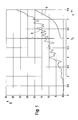
- Fig. 1 which shows a graphical representation of a slip angle curve 5 in an estimated representation in comparison to a reference floating angle 3.
- the actual slip angle ⁇ is plotted over time t as a reference float angle 3 in its evolution in a spin process.
- curve 5 a second, estimated by the algorithm float angle is shown.
- the vehicle is in an initial driving state in which the reference floating angle 3 is initially low, but then increases by a critical driving state, until the vehicle enters into a spin operation at a breaking point t x .
- the second estimated float angle 5 with its start value in this example is 2 °.
- This starting value results from a constant, as already listed in the prior art.
- the slip angle is now further calculated in the algorithm as a function of dynamic driving values. It can be clearly seen that this calculated value follows the course of the actual slip angle 3, but there is a difference of about 11 °, which is also referred to as a phase delay.
- v x is the vehicle speed and ⁇ is the estimated slip angle 5. Accordingly, the slip angle ⁇ , which is 11 ° lower than the actual slip angle, also results too low lateral velocity, which can lead to too late release of restraints.
- the present invention now makes it possible to continuously calculate the starting value of the slip angle so that it corresponds as exactly as possible to the break-away time t x the actual slip angle, so that the algorithm can perform a further correct calculation.
- FIG. 2 a state diagram of a driving dynamics algorithm with four state phases 10, 11, 12 and 13, which passes through a vehicle in a spin operation in succession.
- solid arrows indicate transitions between the state phases
- dashed arrows indicate the transfer of values between the state phases.
- the current arrangement of the driving dynamics algorithm is by detecting the longitudinal velocity v x , the yaw rate ⁇ z (ie the rate of rotation about the vertical axis of the vehicle), the lateral acceleration a y , and optionally the wheel speeds, the longitudinal acceleration a x and an estimate of the slip angle ⁇ (which, however, is only valid for small slip angles).
- the first state phase 10 indicates the stable driving state of the vehicle.
- the start value of the float angle is transferred as the initial float angle ⁇ init to the second state phase 11, which identifies the break-out state of the vehicle.
- the slip angle ⁇ 1 is calculated starting from the initial float angle ⁇ init and transferred to the third state phase 12 during spin detection, which identifies the spin state of the vehicle.
- a further calculation of v x and ⁇ 2 for transfer to a third state phase 13 ensues. If it is recognized during the state phases 11, 12 and 13 that a stable state again occurs, then the algorithm returns to the respectively preceding state phase.
- the determination of the initial float angle ⁇ init takes place in the first state phase 10, which is described in FIG Fig. 3 is shown.
- the state phase 10 is shown enlarged with an initial float angle determination unit 14 having a first subphase unit 15 and a second subphase unit 16.
- the thereby improved Clearschwimmwinkelab runs in the background in the first state phase 10 from.
- the initial floating angle determined in the second subphase unit 16 is then transferred to the second state phase 11 as the initial floating angle ⁇ init when the vehicle detects an outbreak.
- the vehicle In the state phase 10, the vehicle is in normal operation, ie in a stable driving state. Here, cornering with a low slip angle ⁇ are included. If this condition is present, the slip angle ⁇ and the lateral velocity v y are not of interest for rollover detection since they are too low to initiate a rollover motion. The estimated lateral velocity v y thus becomes zero, which is visible to other algorithms.
- the two subphase units 15 and 16 can be executed. For this a case distinction is made:
- the first subphase unit 15 is relevant to "normal" driving in which small slip angles ⁇ on the order of Y ⁇ 4 ° occur.
- the integration constant Const can be parameterized and has values ⁇ 1, so that the slip angle does not lead to falsifications due to the continuous integration of a slip angle change ⁇ and the associated problem of long-term drift.
- ⁇ 0 is an application and vehicle-dependent value for the initial slip angle ⁇ .
- the float angle change ⁇ results from the magnitudes of the longitudinal and lateral acceleration a x , a y as well as the yaw rate ⁇ z and the vehicle speed v x , which is set equal to the longitudinal speed. are supplied by a sensor located in the vehicle.
- the float angle change ⁇ used here is calculated according to equation (3).
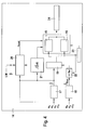
- FIG. 4 illustrated exemplary embodiment of the invention an initial Wegwinkelbeticianstician 14 in block diagram form for the determination of the initial floating angle ⁇ init .
- the driving dynamics variables a x , a y , v x , ⁇ z are supplied from a vehicle dynamics system present in the vehicle or from associated sensors and used by a first and second logic block 17, 18 according to equation (3) for determining the change in the slip angle ⁇ .
- these and the slip angle change ⁇ are fed as input variables to a reset logic 20, which also receives information of a steering angle LW and an initial slip angle ⁇ provided by the driving dynamics.
- a comparison block 22 compares the slip angle change ⁇ with a predefinable threshold value and supplies the result to a third logic block 19, which accordingly decides which subphase unit 15, 16 is used to determine the initial float angle ⁇ init . This is the case distinction mentioned above.
- An integration block 21 first performs the integration of the slip angle change ⁇ for the calculation rules (2) and (5) and forwards them according to the case distinction in the third logic block 19 of the first or second subphase unit 15, 16.
- the first subphase unit 15 performs the determination of the initial floating angle ⁇ init according to the equation (2) and the second subphase unit 16 according to the equation (5).
- the initial float angle ⁇ init calculated in this way is passed to an output block where it is available for forwarding to the next state phase.
- Reset logic 20 determines initial values and constraints for the calculations in subphase units 15 and 16. It also performs a reset to output values when stability is detected.
- a memory device 23 serves to store the predefinable threshold value and other application-dependent and vehicle-dependent values.
- Fig. 5 finally shows the effect of the application of the method according to the invention for determining the initial floating angle ⁇ init .
- the dashed curve with the designation 4 represents the first estimated initial floating angle ⁇ init , which is transferred to the algorithm for the second state phase 11 at break-out time t x .
- the determination according to the invention of the initial float angle ⁇ init follows the mean progression of the reference float angle as the actual slip angle, with no or only a slight difference to the actual slip angle at break-out time t x and the progression of the algorithm from the other State phases calculated second estimated slip angle 5 follows the course of the actual slip angle with very little difference.
- the reliability of the rollover algorithm advantageously increases by improving the lateral velocity estimation.
- Fig. 6 1 shows a schematic block diagram of a device 1 according to the invention in a vehicle 2.
- a sensor system 8, 8 ', 8 is connected to a system control device 7, which is, for example, a vehicle dynamics control system. and wheel speed sensors.
- the sensors 8, 8', 8" can also be connected completely or only partially to the calculation unit 9.
- the calculation unit 9 performs the determination of the initial floating angle ⁇ init .
- the invention is not limited to the embodiments described above, but modifiable in a variety of ways.
- the reliability of other applications that use lateral velocity as the input size can be increased.
- the activation or the improved trigger performance in the side crash triggering called.
- the calculation unit 9 can be implemented by software as a component or a subroutine of the software of the control unit 6.
- calculation unit 9 may be separate or as part of the system control unit 7.
Description
Die vorliegende Erfindung betrifft ein Verfahren und eine Vorrichtung zum Bestimmen eines Initialschwimmwinkels zur Schleudererkennung bei Überrollsensierung.The present invention relates to a method and apparatus for determining an initial buoyancy angle for spin detection in roll sensing.
Die Druckschriften
Eine rechtzeitige Auslöseentscheidung bei Überschlagen mit hoher seitlicher Beschleunigung durch Einbeziehen eines so genannten Schwimmwinkels und einer Quergeschwindigkeit des Fahrzeugs sowie einer Fahrzeugkippbewegung wird in der Druckschrift
Die Bestimmung des Schwimmwinkels in einem Winkelbereich, der größer als 20° ist, und daraus der lateralen Geschwindigkeit, wie sie für die Überschlagserkennung benötigt wird, ist jedoch nicht durch bekannte Verfahren ausführbar, wie sie z.B. in der Fahrdynamikregelung eingesetzt werden. Diese sind nur für Winkelbereiche unterhalb von 10° geeignet, wie z.B. Verfahren, die ein Modell aus Reifencharakteristik und die Seitenführungskraft verwenden. Der geringe Gültigkeitsbereich ist darin begründet, dass eine Fahrdynamikregelung bei größeren Schwimmwinkeln nicht mehr erfolgreich durchgeführt werden kann.However, the determination of the slip angle in an angular range greater than 20 °, and hence the lateral velocity required for rollover detection, can not be accomplished by known methods, such as e.g. be used in the vehicle dynamics control. These are only suitable for angular ranges below 10 °, as e.g. Procedures using a tire characteristic model and cornering force. The low validity is due to the fact that a vehicle dynamics control can no longer be successfully carried out at larger slip angles.
Die
Das erfindungsgemäße Verfahren und die erfindungsgemäße Vorrichtung zum Bestimmen eines Initialschwimmwinkels zur Schleudererkennung bei Überrollsensierung mit den Merkmalen der unabhängigen Patentansprüche 1 und 6 ermöglicht es, dass eine kontinuierliche Initialwinkelschätzung in der ersten Zustandsphase, die den stabilen Fahrzustand des Fahrzeugs kennzeichnet durchgeführt wird. Das hat den demgegenüber den Vorteil, dass auch bei schon größeren Schwimmwinkeln ein korrektes "Aufsetzen" des Algorithmus gegeben ist, woraus sich dann eine korrekte Lateralgeschwindigkeit ergibt.The inventive method and the device according to the invention for determining an initial floating angle for spin detection in the case of roll sensing with the features of
Die Grundidee der Erfindung wird im Folgenden erläutert.The basic idea of the invention will be explained below.
Kern der Erfindung ist eine kontinuierliche Initialschwimmwinkeleinschätzung, welche im Falle eines Ausbrechens des Fahrzeugs zum Startwinkel des Algorithmus verwendet wird. Der ermittelte Startwinkel kann dabei Größen von ±0 bis zu einem parametrisierbaren Werte in der Größenordnung von 40° annehmen.The core of the invention is a continuous initial floating angle estimation which is used in the event of the vehicle skipping to the starting angle of the algorithm. The determined starting angle can assume values of ± 0 up to a parametrisable value in the order of 40 °.
In der Praxis treten kritische Fahrmanöver auf, welche speziell bei niedrigen Reibwerten, also auf Eis oder nasser Fahrbahn, zu einem langsamen Anstieg des Schwimmwinkels führen können. Kann dabei das Fahrdynamikregelsystem, wie z.B. ESP, nicht mehr aktiv unterstützen, so erhöht sich die Wahrscheinlichkeit für einen potentiellen Überrollvorgang, bei dem das Fahrzeug lateral in den Seitenstreifen gerät. Dabei können bis zu einem gewissen Zeitpunkt die für den Fahrdynamik-Analyse Algorithmus (FDA oder VDA) bei langsamen Drifts kaum relevante Signale auftreten. Dieses bedeutet, dass die für die Bestimmung der lateralen Geschwindigkeit verwendeten Größen wie Giergeschwindigkeit, Longitudinal- und Lateralbeschleunigung sowie Längsgeschwindigkeit derart sind, dass diese nicht über die eingestellten Schwellwerte zur Aktivierung des Algorithmus führen. Werden die Schwellen jedoch weiter abgesenkt, führt dies zu Misuse-Situationen, die sich in unerwünschten Effekten ausbilden können. Ein wesentlicher Vorteil der Erfindung besteht darin, im Hintergrund eine kontinuierliche Initialschwimmwinkelschätzung vorzunehmen und bei Überschreiten der kritischen Schwellen dem Fahrdynamik-Algorithmus einen für die jeweilige Situation angepassten Initalschwimmwinkel zur VerFügung zu stellen.Critical driving maneuvers occur in practice, which can lead to a slow increase in the slip angle, especially at low coefficients of friction, ie on ice or on wet roads. In this case, the driving dynamics control system, such as ESP, do not actively support, so increases the likelihood of a potential rollover process, in which the vehicle laterally gets into the shoulder. At the same time, the signals that are hardly relevant for the driving dynamics analysis algorithm (FDA or VDA) for slow drifts can occur at some point in time. This means that the variables used for the determination of the lateral velocity, such as yaw rate, longitudinal and lateral acceleration as well as longitudinal velocity are such that they do not lead beyond the adjusted threshold values for activating the algorithm. However, lowering the thresholds further leads to misuse situations that may develop into unwanted effects. An essential advantage of the invention is to carry out a continuous initial floating angle estimation in the background and, when the critical thresholds are exceeded, to provide the driving dynamics algorithm with an inital floating angle adapted for the respective situation.
Daraus ergibt sich im Weiteren der Vorteil, dass die Robustheit des Algorithmus bei verbesserter Schätzung der Lateralgeschwindigkeit nicht verschlechtert wird. Die auftretende Differenz bzw. Phasenverschiebung zwischen tatsächlichem und abgeschätztem Schwimmwinkel kann somit minimiert werden, und die Bestimmung der Lateralgeschwindigkeit kann bei erreichen der kritischen Geschwindigkeit exakt wiedergegeben werden. Damit ist eine verbesserte Auslöseperformance zu erzielen, da der Zeitpunkt exakter bestimmt werden kann, an dem sich ggf. ein Fahrzeug im Falle eines Soil-Trip Events überschlägt oder nicht. Damit erhöht sich auch die Zuverlässigkeit von anderen Anwendungen, die die Lateralgeschwindigkeit als Eingabegröße verwenden.This results in the further advantage that the robustness of the algorithm is not degraded with improved estimation of the lateral velocity. The occurring difference or phase shift between the actual and estimated float angle can thus be minimized, and the determination of the lateral speed can be accurately reproduced when the critical speed is reached. This is an improved trigger performance to achieve, since the time can be determined more accurately, where possibly overturns a vehicle in the event of a Soil-trip event or not. This also increases the reliability of other applications that use lateral speed as input.
Ein Verfahren zum Bestimmen eines Initialschwimmwinkels zur Schleudererkennung bei Überrollsensierung eines Überrollvorgangs eines Fahrzeugs mit mindestens einer Sensorik für fahrzeugdynamische Signale und einem Steuergerät zur Aktivierung von Rückhaltemitteln, welches den Fahrzustand des Fahrzeugs in zeitlich aufeinander folgende Zustandsphasen aufteilt, mit folgenden, in der ersten Zustandsphase kontinuierlich ausgeführten Verfahrensschritten:
- (S1) Berechnen einer Schwimmwinkeländerung aus den fahrzeugdynamischen Signalen;
- (S2) Vergleichen der berechneten Schwimmwinkeländerung mit einem vorgebbaren Schwellwert; und
- (S3) Bestimmen des Initialschwimmwinkels anhand der berechneten Schwimmwinkeländerung in Abhängigkeit von dem Schwellwert für einen ersten Bereich von geringen Schwimmwinkeländerungen oder für einen zweiten Bereich von größeren Werten von Schwimmwinkeländerungen.
- (S1) calculating a slip angle change from the vehicle dynamic signals;
- (S2) comparing the calculated float angle change with a predefinable threshold value; and
- (S3) determining the initial float angle based on the calculated float angle change as a function of the threshold value for a first range of small float angle changes or for a second range of larger values of slip angle changes.
Dabei ist es vorteilhaft, dass der Verfahrensschritt (S3) folgende Teilschritte aufweist:
- (S3.1) Rücksetzen bzw. Einlesen der Ausgangswerte der fahrzeugdynamischen Signale mittels einer Resetlogik;
- (S3.2) Bestimmen des Initialschwimmwinkels durch Integrieren der berechneten Schwimmwinkeländerung mit einer Integrationskonstanten im ersten Bereich; oder
- (S3.3) Bestimmen des Initialschwimmwinkels durch Integrieren der berechneten Schwimmwinkeländerung ohne Integrationskonstante im zweiten Bereich;
- (S3.4) Ausgeben des so bestimmten Initialschwimmwinkels für die zweite Zustandsphase bei einem Ausbrechzeitpunkt; oder
- (S3.5) Rückkehr zu Verfahrensschritt, wenn der Vergleich mit dem vorgebbaren Schwellwert wieder den ersten Bereich ergibt.
- (S3.1) resetting or reading in of the output values of the vehicle-dynamic signals by means of a reset logic;
- (S3.2) determining the initial float angle by integrating the calculated float angle change with an integration constant in the first range; or
- (S3.3) determining the initial float angle by integrating the calculated float angle change without integration constant in the second range;
- (S3.4) outputting the thus-determined initial floating angle for the second state phase at a break-out timing; or
- (S3.5) Return to process step if the comparison with the predefinable threshold again gives the first range.
Die Integrationskonstante ist parametrisierbar und weist Werte <1 auf. Daraus ergibt sich vorteilhaft, dass der Schwimmwinkel auf Grund der kontinuierlichen Integration und der damit verbundenen Problematik von Langzeitdrift nicht zu Verfälschungen führt.The integration constant can be parametrised and has values <1. This results in advantageous that the slip angle does not lead to falsifications due to the continuous integration and the associated problem of long-term drift.
Es ist bevorzugt, den ersten Bereich von geringen Schwimmwinkeländerungen (β̇) für 0° < |β| < 4° und den zweite Bereich von größeren Schwimmwinkeländerungen (β̇) für Y° < |β| < X° auszubilden, und dass der Parameter Y und X vorgebbar bzw. parametrisierbar ist. Hierbei lassen sich vorteilhaft Geradeausfahrten von dynamischen Kurvenfahrten trennen, wobei bei Kurvenfahrten die Wahrscheinlichkeit eines Ausbrechens größer list.It is preferable to have the first range of small slip angle changes (β̇) for 0 ° <| β | <4 ° and the second range of larger slip angle changes (β̇) for Y ° <| β | <X °, and that the parameters Y and X can be specified or parameterized. In this case, it is advantageous to separate straight-ahead driving from dynamic cornering, whereby, when cornering, the probability of breaking out is greater.
Eine Vorrichtung gemäß dem Verfahren zur Bestimmung eines zur Schleudererkennung bei Überrollsensierung eines Überrollvorgangs eines Fahrzeugs mit mindestens einer Sensorik für fahrzeugdynamische Signale und einem Steuergerät zur Aktivierung von Rückhaltemitteln, welches den Fahrzustand des Fahrzeugs in zeitlich aufeinander folgende Zustandsphasen aufteilt, ist dadurch gekennzeichnet, dass die Vorrichtung eine Berechnungseinheit zur kontinuierlichen Berechnung des Initialschwimmwinkels aufweist.A device according to the method for determining a spin detection in Überrollsensierung a rollover event of a vehicle with at least one sensor for vehicle dynamics signals and a control device for activating restraint means, which divides the driving condition of the vehicle in successive stages of state, is characterized in that the device a calculation unit for continuously calculating the initial floating angle.
Bei einer besonders bevorzugten Ausführungsform weist die Berechnungseinheit eine Initialschwimmwinkelbestimmungseinheit auf mit:
- einem ersten Logikblock zur Ermittlung einer Schwimmwinkeländerung aus den fahrzeugdynamischen Signalen;
- einem zweiten Logikblock zur Ermittlung einer Schwimmwinkeländerung aus dep fahrzeugdynamischen Signalen;
- einem Vergleichsblock zum Vergleich der Schwimmwinkeländerung aus dem zweiten Logikblock und zur Ausgabe eines Vergleichssignals;
- einem dritten Logikblock zur Auswahl einer Subphaseneinheit anhand des Vergleichssignals aus dem Vergleichsblock;
- einem Integrationsblock zur Integration der vom ersten Logikblock gelieferten Schwimmwinkeländerung;
- einer Resetlogik zum Rücksetzen bzw. Ermitteln der Ausgangswerte der fahrzeugdynamischen Signale;
- einer ersten Subphaseneinheit zur Berechnung des Initialschwimmwinkels mit einer ersten Berechnungsvorschrift unter Verwendung der Ausgabewerte der Resetlogik und des Integrationsblocks;
- einem Ausgabeblock zur Ausgabe des berechneten Initialschwimmwinkels an eine nachfolgende zweite Zustandsphase; und mit
- einer Speichereinrichtung zur Speicherung von vorgebbaren Datenwerten.
- a first logic block for determining a float angle change from the vehicle-dynamic signals;
- a second logic block for determining a float angle change from dep vehicle dynamic signals;
- a comparison block for comparing the float angle change from the second logic block and for outputting a comparison signal;
- a third logic block for selecting a subphase unit based on the comparison signal from the comparison block;
- an integration block for integrating the float angle change provided by the first logic block;
- a reset logic for resetting or determining the output values of the vehicle-dynamic signals;
- a first subphase unit for calculating the initial buoyancy angle with a first calculation rule using the output values of the reset logic and the integration block;
- an output block for outputting the calculated initial floating angle to a subsequent second state phase; and with
- a memory device for storing predefinable data values.
Es ist vorteilhaft, dass die Berechnungseinheit als Bestandteil der Software des Steuergeräts ausgebildet ist, da somit kein zusätzlicher Bauraum für die erfindungsgemäße Vorrichtung benötigt wird.It is advantageous that the calculation unit is formed as part of the software of the control unit, since thus no additional space for the device according to the invention is needed.
Vorteilhafte Ausgestaltungen und Weiterbildungen der Erfindung sind den Unteransprüchen und der Beschreibung unter Bezugnahme auf die Zeichnungen entnehmbar.Advantageous embodiments and further developments of the invention are the dependent claims and the description with reference to the drawings.
Die Erfindung wird nachfolgend anhand des in der Figur der Zeichnung angegebenen Ausführungsbeispiels näher erläutert.The invention will be explained in more detail with reference to the embodiment shown in the figure of the drawing.
Es zeigt dabei:
- FIG. 1
- eine grafische Darstellung eines Schwimmwinkelverlaufs in geschätzter Darstellung im Vergleich zu einem Referenzschwimmwinkel gemäß dem Stand der Technik;
- FIG. 2
- ein Zustandsdiagramm eines Fahrdynamikalgorithmus;
- FIG. 3
- ein Zustandsdiagramm eines Fahrdynamikalgorithmus in einer erfindungsgemäßen Ausführung;
- FIG. 4
- ein Blockschaltbild einer erfindungsgemäßen Ausführungsform einer Initialschwimmwinkelbestimmungseinheit;
- FIG. 5
- eine grafische Darstellung eines Schwimmwinkelverlaufs mit kontinuierlicher Abschätzung im Vergleich zu einem Referenzschwimmwinkel gemäß einer Ausführungsform der vorliegenden Erfindung; und
- FIG.6
- eine schematische Blockdarstellung einer erfindungsgemäßen Vorrichtung.
- FIG. 1
- a graphical representation of a slip angle course in an estimated representation compared to a reference floating angle according to the prior art;
- FIG. 2
- a state diagram of a vehicle dynamics algorithm;
- FIG. 3
- a state diagram of a driving dynamics algorithm in an embodiment according to the invention;
- FIG. 4
- a block diagram of an embodiment according to the invention an initial Schwimmwinkelbestimmungseinheit;
- FIG. 5
- FIG. 4 is a graph of a continuous-angle fl ow angle versus a reference fl oating angle according to one embodiment of the present invention; FIG. and
- FIG.6
- a schematic block diagram of a device according to the invention.
Die Bedeutung der passiven Sicherheit bei Fahrzeugüberschlägen ist sehr hoch, da ein großer Anteil von tödlichen Einzelfahrzeug-Unfällen auf einen Überschlag zurückgeführt werden kann. Im gesamten Unfallgeschehen nimmt der Fahrzeugüberschlag oder -überrollvorgang zur Zeit einen Anteil von rund 20 Prozent ein.The importance of passive safety in vehicle rollovers is very high, as a large proportion of fatal single-vehicle accidents can be attributed to a rollover. In the entire accident scene, the vehicle rollover or rollover process currently accounts for about 20 percent.
Vor diesem Hintergrund gibt es Konzepte für die Überrollsensierung, welche zum Beispiel einen Fahrzeugüberschlag bereits zu einem frühen Zeitpunkt erkennen können. Damit wird gewährleistet, dass Sicherheitsvorrichtungen wie Gurtstraffer, Kopfairbag und Überrollbügel rechtzeitig aktiviert werden und ein Verletzungsrisiko verringert wird. Bisherige Systeme zur Überschlagserkennung betrachten die Wankbewegung und die Beschleunigungen in x-, y- und z-Richtung des Fahrzeugs. Auf dieser Basis ist eine sichere Erkennung eines Überschlags des Fahrzeugs möglich. Die Entscheidung kann jedoch erst zu einem späten Zeitpunkt des Überrollvorgangs sicher getroffen werden, der typischerweise bei einem Wankwinkel von 20° bis 40° liegt. Bei bestimmten Fällen von Fahrzeugüberschlägen ist dies aber zu spät, z.B. bei so genannten Soil-Trips, bei denen das Fahrzeug auf den Randstreifen gerät und durch die unterschiedlichen Beschaffenheiten von Straße und Randstreifen ins Schleudern geraten kann. Eine solche Entscheidung zu spät zu treffen, kann die Insassen dabei nicht mehr hinreichend schützen, da sie durch eine hohe laterale Beschleunigung bereits eine Seitwärtsverlagerung erfahren haben, die den Nutzen von z.B. Windowairbags einschränkt.Against this background, there are concepts for the roll-over sensing, which can detect, for example, a vehicle rollover at an early stage. This ensures that safety devices such as belt tensioners, head airbags and roll bars are activated in good time and a risk of injury is reduced. Previous systems for rollover detection consider the rolling motion and the accelerations in the x-, y- and z-direction of the vehicle. On this basis, a safe detection of a rollover of the vehicle is possible. However, the decision can be made only at a late time of rollover safely, which is typically at a roll angle of 20 ° to 40 °. In certain cases of vehicle rollovers, however, this is too late, for example in the case of so-called soil trips, in which the vehicle gets caught on the edge strip and can get into a spin due to the different characteristics of the road and edge strips. Making such a decision too late can not adequately protect the occupants, since they have already experienced lateral displacement due to high lateral acceleration, which limits the usefulness of, for example, window airbags.
Um diese zu späte Entscheidung früher treffen zu können, wird bei einer Überschlagserkennung ein Schwimmwinkel des Fahrzeugs mit einbezogen, wie im Stand der Technik oben aufgeführt ist. Zur Illustration der Ausgangssituation, bei der die vorliegende Erfindung ansetzt, dient die
Der tatsächliche Schwimmwinkel β ist über der Zeit t als ein Referenzschwimmwinkel 3 in seiner Entwicklung bei einem Schleudervorgang aufgetragen. Mit der Kurve 5 ist ein zweiter, durch den Algorithmus geschätzter Schwimmwinkel dargestellt. Das Fahrzeug befindet sich in einem anfänglichen Fahrzustand, in dem der Referenzschwimmwinkel 3 zunächst gering ist, sich dann aber durch einen kritischer werdenden Fahrzustand erhöht, bis dass das Fahrzeug in einem Ausbrechzeitpunkt tx in einen Schleudervorgang eintritt. Zu diesem Zeitpunkt beträgt der zweite geschätzte Schwimmwinkel 5 mit seinem Startwert in diesem Beispiel 2°. Dieser Startwert ergibt sich aus einer Konstanten, wie zum Stand der Technik bereits aufgeführt. Von diesem Startwert an wird der Schwimmwinkel nun im Algorithmus in Abhängigkeit von fahrdynamischen Werten weiter berechnet. Es ist deutlich zu erkennen, dass dieser berechnete Wert dem Verlauf des tatsächlichen Schwimmwinkels 3 folgt, jedoch ist eine Differenz von rund 11° zu verzeichnen, die auch als ein Phasenverzug bezeichnet wird.The actual slip angle β is plotted over time t as a
Dieser zweite geschätzte Schwimmwinkel 5 wird nun zur Berechnung einer Lateralgeschwindigkeit vy mit folgender Gleichung verwendet: 
Hierbei ist vx die Fahrzeuggeschwindigkeit und β der geschätzte Schwimmwinkel 5. Mit dem zum tatsächlichen Schwimmwinkel um 11° niedrigeren Schwimmwinkel β ergibt sich demzufolge auch eine zu niedrige Lateralgeschwindigkeit, welche zu einer zu späten Auslösung von Rückhaltemitteln führen kann.In this case, v x is the vehicle speed and β is the estimated
Die vorliegende Erfindung ermöglicht es nun, den Startwert des Schwimmwinkels kontinuierlich zu berechnen, so dass er zum Ausbrechzeitpunkt tx dem tatsächlichen Schwimmwinkel möglichst genau entspricht, so dass der Algorithmus eine weitere korrekte Berechnung durchführen kann.The present invention now makes it possible to continuously calculate the starting value of the slip angle so that it corresponds as exactly as possible to the break-away time t x the actual slip angle, so that the algorithm can perform a further correct calculation.
Eine mögliche Realisierung wird in einer beispielhaften Ausführungsform im Folgenden beschrieben. Hierzu zeigt die
Die derzeitige Anordnung des Fahrdynamikalgorithmus ist dabei durch eine Erfassung der Längsgeschwindigkeit vx, der Gierrate ωz (d.h. der Drehrate um die Hochachse des Fahrzeugs), der lateralen Beschleunigung ay, und optional der Raddrehzahlen, der Längsbeschleunigung ax und einer Schätzung des Schwimmwinkels β (die jedoch nur für kleine Schwimmwinkel Gültigkeit hat) gekennzeichnet.The current arrangement of the driving dynamics algorithm is by detecting the longitudinal velocity v x , the yaw rate ω z (ie the rate of rotation about the vertical axis of the vehicle), the lateral acceleration a y , and optionally the wheel speeds, the longitudinal acceleration a x and an estimate of the slip angle β (which, however, is only valid for small slip angles).
Die erste Zustandsphase 10 kennzeichnet den stabilen Fahrzustand des Fahrzeugs. Zum Ausbrechzeitpunkt wird der Startwert des Schwimmwinkels als Initialschwimmwinkel βinit an die zweite Zustandsphase 11 übergeben, die den Ausbrechzustand des Fahrzeugs kennzeichnet. Hierbei wird der Schwimmwinkel β1 ausgehend vom Initialschwimmwinkel βinit berechnet und der dritten Zustandsphase 12 bei Schleudererkennung übergeben, welche den Schleuderzustand des Fahrzeugs kennzeichnet. Eine weitere Berechnung von vx und β2 zur Übergabe an eine dritte Zustandsphase 13 erfolgt darauf. Wird während der Zustandsphasen 11, 12 und 13 erkannt, dass wieder ein stabiler Zustand eintritt, so kehrt der Algorithmus in die jeweils vorhergehende Zustandsphase zurück.The
Die Bestimmung des Initialschwimmwinkels βinit erfolgt in der ersten Zustandsphase 10, was in
In der Zustandsphase 10 befindet sich das Fahrzeug im Normalbetrieb, d.h. in einem stabilen Fahrzustand. Hierbei werden auch Kurvenfahrten mit einem geringen Schwimmwinkel β mit einbezogen. Liegt dieser Zustand vor, so sind der Schwimmwinkel β und die laterale Geschwindigkeit vy für eine Überschlagserkennung nich von Interesse, da sie zu gering sind, um eine Überschlagsbewegung einzuleiten. Die geschätzte laterale Geschwindigkeit vy ergibt sich damit zu Null, welches für andere Algorithmen sichtbar ist. In dieser ersten Zustandsphase 10 können die beiden Subphaseneinheiten 15 und 16 ausgeführt werden. Hierzu wird eine Fallunterscheidung getroffen:In the
Für die erste Subphaseneinheit 15 gilt: 0° < |β| < Y°
Die erste Subphaseneinheit 15 ist relevant für "normales" Fahren, bei dem kleine Schwimmwinkel β in der Größenordnung von Y ≈ 4° auftreten. Dabei berechnet sich der geschätzte Initialschwimmwinkel βinit aus: ![]()
The ![]()
Die Integrationskonstante Const ist dabei parametriesierbar und weist Werte <1 auf, so dass der Schwimmwinkel auf Grund der kontinuierlichen Integration einer Schwimmwinkeländerung β̇ und der damit verbundenen Problematik von Langzeitdrift nicht zu Verfälschungen führt. Hierbei ist β0 ein applikations- und fahrzeugabhängiger Wert für den anfänglichen Schwimmwinkel β. Dabei ergibt sich die Schwimmwinkeländerung β̇aus den Größen der Longitudinal- und Querbeschleunigung ax, ay sowie der Gierrate ωz und der Fahrzeuggeschwindigkeit vx, welche der Longitudinalgeschwindigkeit gleichgesetzt wird. werden von einer im Fahrzeug befindlichen Sensorik geliefert. Die Schwimmwinkeländerung β̇berechnet sich wie folgt: 
Für die zweite Subphaseneinheit 16 gilt: 4° < |β| < X°
Hierbei ist Y und X parametriesierbar.For the second subphase unit 16: 4 ° <| β | <X °
Here, Y and X can be parameterized.
Kommt es zu einem Aufbau von größeren Schwimmwinkeländerungen, wie z.B. bei sehr dynamischem Fahren in Autobahnauffahrten bzw. -abfahrten, dann wird über die einfache Beziehung 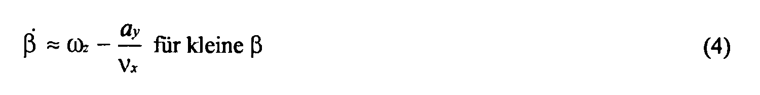
![]()
![]()
Die dabei verwendete Schwimmwinkeländerung β̇berechnet sich nach Gleichung (3).The float angle change β̇ used here is calculated according to equation (3).
Daraus ergibt sich zusammengefasst eine in
Die fahrdynamischen Größen ax, ay, vx, ωz werden aus einem im Fahrzeug vorhandenen Fahrdynamiksystem bzw. von zugehörigen Sensoren geliefert und von einer ersten und zweiten Logikblock 17, 18 gemäß Gleichung (3) zur Bestimmung der Schwimmwinkeländerung β̇verwendet. Gleichzeitig werden diese und die Schwimmwinkeländerung β̇als Eingangsgrößen einer Resetlogik 20 zugeleitet, die auch eine Information eines Lenkwinkels LW und eines von der Fahrdynamik bereitgestellten anfänglichen Schwimmwinkels β erhält.The driving dynamics variables a x , a y , v x , ω z are supplied from a vehicle dynamics system present in the vehicle or from associated sensors and used by a first and
Ein Vergleichsblock 22 vergleicht die Schwimmwinkeländerung β̇mit einem vorgebbaren Schwellwert und leitet das Ergebnis einem dritten Logikblock 19 zu, welcher dementsprechend entscheidet, welche Subphaseneinheit 15, 16 zur Bestimmung des Initialschwimmwinkels βinit verwendet wird. Dieses ist die oben erwähnte Fallunterscheidung.A
Ein Integrationsblock 21 führt zunächst die Integration der Schwimmwinkeländerung β̇für die Berechnungsvorschriften (2) und (5) durch und leitet diese entsprechend der Fallunterscheidung im dritten Logikblock 19 der ersten oder zweiten Subphaseneinheit 15, 16 zu.An
Die erste Subphaseneinheit 15 führt die Bestimmung des Initialschwimmwinkels βinit nach Gleichung (2) und die zweite Subphaseneinheit 16 nach Gleichung (5) durch.The
Der so berechnete Initialschwimmwinkels βinit wird an einen Ausgabeblock geleitet und steht dort der nächsten Zustandsphase zur Weiterleitung zur Verfügung.The initial float angle β init calculated in this way is passed to an output block where it is available for forwarding to the next state phase.
Die Resetlogik 20 ermittelt Anfangswerte und Randbedingungen für die Berechnungen in den Subphaseneinheiten 15 und 16. Sie führt auch eine Rückstellung auf Ausgangswerte aus, wenn eine Stabilität erkannt wird.
Eine Speichereinrichtung 23 dient zur Speicherung des vorgebbaren Schwellwertes und weiterer applikations- und fahrzeugabhängiger Werte.A
Daraus erhöht sich die Zuverlässigkeit des Überrollalgorithmus vorteilhaft, indem die Schätzung der Lateralgeschwindigkeit verbessert ist.From this, the reliability of the rollover algorithm advantageously increases by improving the lateral velocity estimation.
Die Erfindung ist nicht auf die oben beschriebenen Ausführungsbeispiele beschränkt, sondern auf vielfältige Art und Weise modifizierbar.The invention is not limited to the embodiments described above, but modifiable in a variety of ways.
Auch die Zuverlässigkeit von anderen Anwendungen, welche die Lateralgeschwindigkeit als Eingabegröße verwenden, kann erhöht werden. Als Beispiel sei die Aktivierung bzw. die verbesserte Auslösungsperformance bei der Seitencrashauslösung genannt.Also, the reliability of other applications that use lateral velocity as the input size can be increased. As an example, the activation or the improved trigger performance in the side crash triggering called.
Die Berechnungseinheit 9 kann softwaremäßig als ein Bestandteil bzw. ein Unterprogramm der Software des Steuergeräts 6 ausgeführt sein.The calculation unit 9 can be implemented by software as a component or a subroutine of the software of the
Es ist auch denkbar, dass die Berechnungseinheit 9 separat oder als ein Bestandteil des Systemsteuergeräts 7 sein kann.It is also conceivable that the calculation unit 9 may be separate or as part of the
Claims (8)
- Method for determining an initial attitude angle (βinit) in order to detect skidding during roll-over sensing of a roll-over process of a vehicle (2), comprising at least one sensor system (8, 8', 8") for vehicle dynamics signals (ax, ay, vx, ωz, LW, β0), and having a control device (6) for activating restraining means which divides the driving state of the vehicle (2) into temporally consecutive state phases (10, 11, 12, 13) the first state phase (10) characterizing the stable driving state of the vehicle, having the following method steps executed continuously in the first state phase (10), characterized by:S1) calculating an attitude angle change (β) from the vehicle dynamics signals (ax, ay, vx, ωz, LW, β);S2) comparing the calculated attitude angle change (β̇) with a prescribable threshold value; andS3) determining the initial attitude angle (βinit) with the aid of the calculated attitude angle change (β̇) as a function of the threshold value for a first range of small attitude angle changes (β̇) or for a second range of larger values of attitude angle changes (β̇).
- Method according to Claim 1, characterized in that the method step (S3) has the following substeps:S3.1) resetting and/or inputting the initial values of the vehicle dynamics signals (ax, ay, vx, ωz, LW, β0) by means of a reset logic (20);S3.2) determining the initial attitude angle (βinit) by integrating the calculated attitude angle change (β̇) with an aid of an integration constant in the first range; orS3.3) determining the initial attitude angle (βinit) by integrating the calculated attitude angle change (β̇) without an integrating constant in the second range;S3.4) outputting the initial attitude angle (βinit) thus determined for the second state phase (11) at a breakaway instant (tx); orS3.5) returning to method step S2) when comparison of the prescribable threshold value once again produces the first range.
- Method according to Claim 2, characterized in that the integration constant is parameterizable and has a value <1.
- Method according to one of Claims 1 to 3, characterized in that the first range of small attitude angle changes (β̇) codes for 0°< |β| < Y°, and the second range of larger attitude angle changes (β̇) codes for Y°< |β| < X°.
- The method as claimed in Claim 4, characterized in that the parameters Y and X are prescribable and/or parameterizable.
- Device for determining an initial attitude angle (βinit) in order to detect skidding during roll-over sensing of a roll-over process of a vehicle (2), comprising at least one sensor system (8, 8', 8") for vehicle dynamics signals (ax, ay, vx, ωz, LW, β0), and having a control device (6) for activating restraining means which divides the driving state of the vehicle (2) into temporally consecutive state phases (10, 11, 12, 13)
characterized
in that the device (1) has a calculation unit (9) for continuous calculation of the initial attitude angle (βinit) in the first state phase (10), which characterizes the stable driving state of the vehicle, having- means for calculating an attitude angle change (β̇) from the vehicle dynamics signals (ax, ay, vx, ωz, LW, (β);- means for comparing the calculated attitude angle change (β̇) with a prescribable threshold value; and- means for determining the initial attitude angle (βinit) with the aid of the calculated attitude angle change (β̇) with a prescribable threshold value; and- means for determining the initial attitude angle (βinit) with the aid of the calculated attitude angle change (β̇) as a function of the threshold value for a first range of small attitude angle changes (β̇) or for a second range of larger values of attitude angle changes (β̇). - Device (1) according to Claim 6, characterized
in that the calculation unit (9) has an initial attitude angle determining unit (14) having:- a first logic block (17) for determining an attitude angle change (β̇) from the vehicle dynamics signals (ax, ay, vx, ωz):- a second logic block (18) for determining an attitude angle change (βStart) from the vehicle dynamics signals (ay, vx, ωz);- a comparison block (22) for comparing the attitude angle change (βStart) from the second logic block (18), and for outputting a comparison signal;- a third logic block (19) for selecting a subphase unit (15, 16) with the aid of the comparison signal from the comparison block (22);- an integration block (21) for integrating the attitude angle change (β̇) applied by the first logic block (17);- a reset logic (20) for resetting and/or determining the initial values of the vehicle dynamics signals (ax, ay, vx, ωz, LW, β0);- a first subphase unit (15) for calculating the initial attitude angle (βinit) with a first calculation rule by using the output values of the reset logic (20) and of the integration block (21);- an output block (24) for outputting the calculated initial attitude angle (βinit) to a downstream second state phase (11); and- a memory device (23) for storing prescribable data values. - Device according to Claim 7, characterized in that the calculation unit (9) is designed as a component of the software of the control device (6).
Applications Claiming Priority (2)
| Application Number | Priority Date | Filing Date | Title |
|---|---|---|---|
| DE102005008976A DE102005008976A1 (en) | 2005-02-28 | 2005-02-28 | Method and device for determination of initial floating angle of vehicle before overturning, comprising use of speed sensors and appropriate algorithms |
| PCT/EP2005/057235 WO2006092183A1 (en) | 2005-02-28 | 2005-12-30 | Method and device for determining an initial attitude angle in order to detect swerving during overroll detection |
Publications (2)
| Publication Number | Publication Date |
|---|---|
| EP1855918A1 EP1855918A1 (en) | 2007-11-21 |
| EP1855918B1 true EP1855918B1 (en) | 2008-07-23 |
Family
ID=36143712
Family Applications (1)
| Application Number | Title | Priority Date | Filing Date |
|---|---|---|---|
| EP05850511A Active EP1855918B1 (en) | 2005-02-28 | 2005-12-30 | Method and device for determining an initial attitude angle in order to detect swerving during overroll detection |
Country Status (6)
| Country | Link |
|---|---|
| US (1) | US8116949B2 (en) |
| EP (1) | EP1855918B1 (en) |
| JP (1) | JP4814260B2 (en) |
| DE (2) | DE102005008976A1 (en) |
| ES (1) | ES2308600T3 (en) |
| WO (1) | WO2006092183A1 (en) |
Families Citing this family (6)
| Publication number | Priority date | Publication date | Assignee | Title |
|---|---|---|---|---|
| DE102005054127A1 (en) * | 2005-11-14 | 2007-05-16 | Bosch Gmbh Robert | Method and device for controlling personal protective equipment in a rollover process |
| JP5113098B2 (en) * | 2009-01-23 | 2013-01-09 | 日立オートモティブシステムズ株式会社 | Vehicle rollover prevention control device and vehicle rollover prevention control method |
| DE102009047373A1 (en) * | 2009-12-02 | 2011-06-09 | Robert Bosch Gmbh | Method for activating and / or controlling at least one reversible retaining device |
| US9050997B1 (en) | 2010-08-31 | 2015-06-09 | Michael R. Schramm | Rollover prevention apparatus |
| US10562524B2 (en) * | 2017-06-29 | 2020-02-18 | Nio Usa, Inc. | Rollover control algorithm |
| DE102021130478A1 (en) | 2021-11-22 | 2023-05-25 | Man Truck & Bus Se | Method for detecting an accident situation involving a commercial vehicle |
Family Cites Families (15)
| Publication number | Priority date | Publication date | Assignee | Title |
|---|---|---|---|---|
| DE4305155C2 (en) | 1993-02-19 | 2002-05-23 | Bosch Gmbh Robert | Device for regulating the driving dynamics |
| DE19708508A1 (en) | 1996-09-24 | 1998-03-26 | Bosch Gmbh Robert | Method and device for regulating a movement quantity representing the movement of the vehicle |
| US6266599B1 (en) * | 1996-09-24 | 2001-07-24 | Robert Bosch Gmbh | Method and device for adjusting an amount of movement representing the vehicle motion |
| DE19813019A1 (en) * | 1998-03-25 | 1999-09-30 | Bosch Gmbh Robert | Method and device for controlling at least one driving dynamics variable of a vehicle |
| DE19828338A1 (en) | 1998-06-25 | 1999-12-30 | Bosch Gmbh Robert | Determining critical angle of motor vehicle leading to rollover |
| DE10019417A1 (en) | 2000-04-19 | 2001-10-25 | Bosch Gmbh Robert | Rollover detection system, compares angular rates with predicted critical value more accurate than angle criterion |
| DE10019416A1 (en) | 2000-04-19 | 2001-10-25 | Bosch Gmbh Robert | Rollover decision system, compares rotation rates with normal maneuver envelope ensures plausibility |
| DE10102002A1 (en) * | 2001-01-18 | 2002-07-25 | Bosch Gmbh Robert | Method and device for coordinating interventions in the driving behavior of a vehicle |
| DE10122654A1 (en) * | 2001-05-10 | 2002-12-05 | Bosch Gmbh Robert | Method and system for regulating the driving behavior of a vehicle |
| DE10149112B4 (en) * | 2001-10-05 | 2004-11-25 | Robert Bosch Gmbh | Method for determining a triggering decision for restraint devices in a vehicle |
| JP2003146199A (en) * | 2001-11-15 | 2003-05-21 | Honda Motor Co Ltd | Estimation method of vehicle state quantity |
| DE10239406A1 (en) * | 2002-08-28 | 2004-03-11 | Robert Bosch Gmbh | Vehicle rollover detection device |
| JP2005087924A (en) * | 2003-09-18 | 2005-04-07 | Dowa Mining Co Ltd | Method for treating soil or ash containing chlorinated aromatic compound |
| DE10350920A1 (en) * | 2003-10-31 | 2005-05-25 | Robert Bosch Gmbh | Device for determining a pivot point of a vehicle about a vehicle vertical axis |
| US7162340B2 (en) * | 2004-01-08 | 2007-01-09 | Delphi Technologies, Inc. | Vehicle rollover detection and method of anticipating vehicle rollover |
-
2005
- 2005-02-28 DE DE102005008976A patent/DE102005008976A1/en not_active Withdrawn
- 2005-12-30 EP EP05850511A patent/EP1855918B1/en active Active
- 2005-12-30 WO PCT/EP2005/057235 patent/WO2006092183A1/en active Application Filing
- 2005-12-30 DE DE502005004851T patent/DE502005004851D1/en active Active
- 2005-12-30 US US11/885,290 patent/US8116949B2/en not_active Expired - Fee Related
- 2005-12-30 ES ES05850511T patent/ES2308600T3/en active Active
- 2005-12-30 JP JP2007556505A patent/JP4814260B2/en not_active Expired - Fee Related
Also Published As
| Publication number | Publication date |
|---|---|
| DE102005008976A1 (en) | 2006-08-31 |
| JP4814260B2 (en) | 2011-11-16 |
| DE502005004851D1 (en) | 2008-09-04 |
| US8116949B2 (en) | 2012-02-14 |
| ES2308600T3 (en) | 2008-12-01 |
| EP1855918A1 (en) | 2007-11-21 |
| JP2008531362A (en) | 2008-08-14 |
| WO2006092183A1 (en) | 2006-09-08 |
| US20090216409A1 (en) | 2009-08-27 |
Similar Documents
| Publication | Publication Date | Title |
|---|---|---|
| EP1846269B1 (en) | Triggering method for activating a lateral speed estimation for passenger protection devices | |
| EP1945483B1 (en) | Method and apparatus for detemrining a roll angle for occupant protection apparatuses | |
| EP1157898B1 (en) | Method for rollover detection of vehicles with safety system | |
| EP1157899B1 (en) | Process and safety system for detecting a roll-over and for enabling a safety device in a motor vehicle | |
| EP1599365B1 (en) | Method for generating a firing decision for a restraining system | |
| DE102005047021B3 (en) | Arrangement for determining an absolute angle of inclination with respect to the horizontal | |
| DE10330539B4 (en) | A crash event detection system and method of operating such a system | |
| EP1758768B1 (en) | Method for determining a decision for triggering retaining means in a motor vehicle | |
| DE102010027969B4 (en) | Method and device for determining a type of impact of an object on a vehicle | |
| EP1855918B1 (en) | Method and device for determining an initial attitude angle in order to detect swerving during overroll detection | |
| DE102005037961B4 (en) | Method and device for detecting a side impact location | |
| DE10123215A1 (en) | Method for activating an occupant protection application in a motor vehicle | |
| EP3597452B1 (en) | Method and device for estimating a current circumference of at least one wheel located on a vehicle | |
| EP1599364B1 (en) | Method and device for determining the probability of an accident for a vehicle | |
| DE602004013303T2 (en) | A method and system for detecting a vehicle rollover condition | |
| DE102014107089A1 (en) | External airbag deployment method | |
| DE10333990A1 (en) | An occupant protection device for a vehicle and method for driving an occupant protection device for a vehicle for early detection of a critical driving situation | |
| EP1536986B1 (en) | Device for recognizing a vehicle overturn | |
| EP1861292B1 (en) | Method and device for determining the rolling angle for passenger protection devices | |
| EP1951555B1 (en) | Method and device for activating personal protection means in the event of a rollover | |
| DE602004007270T2 (en) | Method and system for detecting a vehicle rollover | |
| EP1820701B1 (en) | Device for controlling rollover protection devices in a vehicle | |
| EP1551670B1 (en) | Method for activating a restraint system in a vehicle | |
| EP2674332A1 (en) | Control device and method for controlling a safety apparatus for a vehicle in a rollover situation | |
| DE102010008406A1 (en) | Method and device for detecting a rollover situation in a vehicle |
Legal Events
| Date | Code | Title | Description |
|---|---|---|---|
| PUAI | Public reference made under article 153(3) epc to a published international application that has entered the european phase |
Free format text: ORIGINAL CODE: 0009012 |
|
| 17P | Request for examination filed |
Effective date: 20070928 |
|
| AK | Designated contracting states |
Kind code of ref document: A1 Designated state(s): DE ES FR GB |
|
| 17Q | First examination report despatched |
Effective date: 20071227 |
|
| GRAP | Despatch of communication of intention to grant a patent |
Free format text: ORIGINAL CODE: EPIDOSNIGR1 |
|
| RBV | Designated contracting states (corrected) |
Designated state(s): DE ES FR GB |
|
| DAX | Request for extension of the european patent (deleted) | ||
| GRAS | Grant fee paid |
Free format text: ORIGINAL CODE: EPIDOSNIGR3 |
|
| GRAA | (expected) grant |
Free format text: ORIGINAL CODE: 0009210 |
|
| AK | Designated contracting states |
Kind code of ref document: B1 Designated state(s): DE ES FR GB |
|
| REG | Reference to a national code |
Ref country code: GB Ref legal event code: FG4D Free format text: NOT ENGLISH |
|
| REF | Corresponds to: |
Ref document number: 502005004851 Country of ref document: DE Date of ref document: 20080904 Kind code of ref document: P |
|
| REG | Reference to a national code |
Ref country code: ES Ref legal event code: FG2A Ref document number: 2308600 Country of ref document: ES Kind code of ref document: T3 |
|
| PLBE | No opposition filed within time limit |
Free format text: ORIGINAL CODE: 0009261 |
|
| STAA | Information on the status of an ep patent application or granted ep patent |
Free format text: STATUS: NO OPPOSITION FILED WITHIN TIME LIMIT |
|
| 26N | No opposition filed |
Effective date: 20090424 |
|
| REG | Reference to a national code |
Ref country code: FR Ref legal event code: PLFP Year of fee payment: 11 |
|
| REG | Reference to a national code |
Ref country code: FR Ref legal event code: PLFP Year of fee payment: 12 |
|
| REG | Reference to a national code |
Ref country code: FR Ref legal event code: PLFP Year of fee payment: 13 |
|
| PGFP | Annual fee paid to national office [announced via postgrant information from national office to epo] |
Ref country code: FR Payment date: 20201218 Year of fee payment: 16 Ref country code: GB Payment date: 20201222 Year of fee payment: 16 |
|
| PGFP | Annual fee paid to national office [announced via postgrant information from national office to epo] |
Ref country code: ES Payment date: 20210122 Year of fee payment: 16 |
|
| GBPC | Gb: european patent ceased through non-payment of renewal fee |
Effective date: 20211230 |
|
| PG25 | Lapsed in a contracting state [announced via postgrant information from national office to epo] |
Ref country code: GB Free format text: LAPSE BECAUSE OF NON-PAYMENT OF DUE FEES Effective date: 20211230 |
|
| PG25 | Lapsed in a contracting state [announced via postgrant information from national office to epo] |
Ref country code: FR Free format text: LAPSE BECAUSE OF NON-PAYMENT OF DUE FEES Effective date: 20211231 |
|
| REG | Reference to a national code |
Ref country code: ES Ref legal event code: FD2A Effective date: 20230224 |
|
| PG25 | Lapsed in a contracting state [announced via postgrant information from national office to epo] |
Ref country code: ES Free format text: LAPSE BECAUSE OF NON-PAYMENT OF DUE FEES Effective date: 20211231 |
|
| PGFP | Annual fee paid to national office [announced via postgrant information from national office to epo] |
Ref country code: DE Payment date: 20230223 Year of fee payment: 18 |