EP1945483B1 - Method and apparatus for detemrining a roll angle for occupant protection apparatuses - Google Patents
Method and apparatus for detemrining a roll angle for occupant protection apparatuses Download PDFInfo
- Publication number
- EP1945483B1 EP1945483B1 EP06806815A EP06806815A EP1945483B1 EP 1945483 B1 EP1945483 B1 EP 1945483B1 EP 06806815 A EP06806815 A EP 06806815A EP 06806815 A EP06806815 A EP 06806815A EP 1945483 B1 EP1945483 B1 EP 1945483B1
- Authority
- EP
- European Patent Office
- Prior art keywords
- acceleration
- roll angle
- vehicle
- calculated
- lateral acceleration
- Prior art date
- Legal status (The legal status is an assumption and is not a legal conclusion. Google has not performed a legal analysis and makes no representation as to the accuracy of the status listed.)
- Expired - Fee Related
Links
Images


Classifications
-
- B—PERFORMING OPERATIONS; TRANSPORTING
- B60—VEHICLES IN GENERAL
- B60R—VEHICLES, VEHICLE FITTINGS, OR VEHICLE PARTS, NOT OTHERWISE PROVIDED FOR
- B60R21/00—Arrangements or fittings on vehicles for protecting or preventing injuries to occupants or pedestrians in case of accidents or other traffic risks
- B60R21/01—Electrical circuits for triggering passive safety arrangements, e.g. airbags, safety belt tighteners, in case of vehicle accidents or impending vehicle accidents
- B60R21/013—Electrical circuits for triggering passive safety arrangements, e.g. airbags, safety belt tighteners, in case of vehicle accidents or impending vehicle accidents including means for detecting collisions, impending collisions or roll-over
- B60R21/0132—Electrical circuits for triggering passive safety arrangements, e.g. airbags, safety belt tighteners, in case of vehicle accidents or impending vehicle accidents including means for detecting collisions, impending collisions or roll-over responsive to vehicle motion parameters, e.g. to vehicle longitudinal or transversal deceleration or speed value
-
- B—PERFORMING OPERATIONS; TRANSPORTING
- B60—VEHICLES IN GENERAL
- B60W—CONJOINT CONTROL OF VEHICLE SUB-UNITS OF DIFFERENT TYPE OR DIFFERENT FUNCTION; CONTROL SYSTEMS SPECIALLY ADAPTED FOR HYBRID VEHICLES; ROAD VEHICLE DRIVE CONTROL SYSTEMS FOR PURPOSES NOT RELATED TO THE CONTROL OF A PARTICULAR SUB-UNIT
- B60W40/00—Estimation or calculation of non-directly measurable driving parameters for road vehicle drive control systems not related to the control of a particular sub unit, e.g. by using mathematical models
- B60W40/10—Estimation or calculation of non-directly measurable driving parameters for road vehicle drive control systems not related to the control of a particular sub unit, e.g. by using mathematical models related to vehicle motion
- B60W40/11—Pitch movement
-
- B—PERFORMING OPERATIONS; TRANSPORTING
- B60—VEHICLES IN GENERAL
- B60W—CONJOINT CONTROL OF VEHICLE SUB-UNITS OF DIFFERENT TYPE OR DIFFERENT FUNCTION; CONTROL SYSTEMS SPECIALLY ADAPTED FOR HYBRID VEHICLES; ROAD VEHICLE DRIVE CONTROL SYSTEMS FOR PURPOSES NOT RELATED TO THE CONTROL OF A PARTICULAR SUB-UNIT
- B60W40/00—Estimation or calculation of non-directly measurable driving parameters for road vehicle drive control systems not related to the control of a particular sub unit, e.g. by using mathematical models
- B60W40/10—Estimation or calculation of non-directly measurable driving parameters for road vehicle drive control systems not related to the control of a particular sub unit, e.g. by using mathematical models related to vehicle motion
- B60W40/112—Roll movement
-
- B—PERFORMING OPERATIONS; TRANSPORTING
- B60—VEHICLES IN GENERAL
- B60W—CONJOINT CONTROL OF VEHICLE SUB-UNITS OF DIFFERENT TYPE OR DIFFERENT FUNCTION; CONTROL SYSTEMS SPECIALLY ADAPTED FOR HYBRID VEHICLES; ROAD VEHICLE DRIVE CONTROL SYSTEMS FOR PURPOSES NOT RELATED TO THE CONTROL OF A PARTICULAR SUB-UNIT
- B60W40/00—Estimation or calculation of non-directly measurable driving parameters for road vehicle drive control systems not related to the control of a particular sub unit, e.g. by using mathematical models
- B60W40/10—Estimation or calculation of non-directly measurable driving parameters for road vehicle drive control systems not related to the control of a particular sub unit, e.g. by using mathematical models related to vehicle motion
- B60W40/114—Yaw movement
-
- B—PERFORMING OPERATIONS; TRANSPORTING
- B60—VEHICLES IN GENERAL
- B60R—VEHICLES, VEHICLE FITTINGS, OR VEHICLE PARTS, NOT OTHERWISE PROVIDED FOR
- B60R21/00—Arrangements or fittings on vehicles for protecting or preventing injuries to occupants or pedestrians in case of accidents or other traffic risks
- B60R21/01—Electrical circuits for triggering passive safety arrangements, e.g. airbags, safety belt tighteners, in case of vehicle accidents or impending vehicle accidents
- B60R21/013—Electrical circuits for triggering passive safety arrangements, e.g. airbags, safety belt tighteners, in case of vehicle accidents or impending vehicle accidents including means for detecting collisions, impending collisions or roll-over
- B60R2021/01313—Electrical circuits for triggering passive safety arrangements, e.g. airbags, safety belt tighteners, in case of vehicle accidents or impending vehicle accidents including means for detecting collisions, impending collisions or roll-over monitoring the vehicle steering system or the dynamic control system
-
- B—PERFORMING OPERATIONS; TRANSPORTING
- B60—VEHICLES IN GENERAL
- B60R—VEHICLES, VEHICLE FITTINGS, OR VEHICLE PARTS, NOT OTHERWISE PROVIDED FOR
- B60R21/00—Arrangements or fittings on vehicles for protecting or preventing injuries to occupants or pedestrians in case of accidents or other traffic risks
- B60R21/01—Electrical circuits for triggering passive safety arrangements, e.g. airbags, safety belt tighteners, in case of vehicle accidents or impending vehicle accidents
- B60R21/013—Electrical circuits for triggering passive safety arrangements, e.g. airbags, safety belt tighteners, in case of vehicle accidents or impending vehicle accidents including means for detecting collisions, impending collisions or roll-over
- B60R21/0132—Electrical circuits for triggering passive safety arrangements, e.g. airbags, safety belt tighteners, in case of vehicle accidents or impending vehicle accidents including means for detecting collisions, impending collisions or roll-over responsive to vehicle motion parameters, e.g. to vehicle longitudinal or transversal deceleration or speed value
- B60R2021/01325—Vertical acceleration
-
- B—PERFORMING OPERATIONS; TRANSPORTING
- B60—VEHICLES IN GENERAL
- B60R—VEHICLES, VEHICLE FITTINGS, OR VEHICLE PARTS, NOT OTHERWISE PROVIDED FOR
- B60R21/00—Arrangements or fittings on vehicles for protecting or preventing injuries to occupants or pedestrians in case of accidents or other traffic risks
- B60R21/01—Electrical circuits for triggering passive safety arrangements, e.g. airbags, safety belt tighteners, in case of vehicle accidents or impending vehicle accidents
- B60R21/013—Electrical circuits for triggering passive safety arrangements, e.g. airbags, safety belt tighteners, in case of vehicle accidents or impending vehicle accidents including means for detecting collisions, impending collisions or roll-over
- B60R21/0132—Electrical circuits for triggering passive safety arrangements, e.g. airbags, safety belt tighteners, in case of vehicle accidents or impending vehicle accidents including means for detecting collisions, impending collisions or roll-over responsive to vehicle motion parameters, e.g. to vehicle longitudinal or transversal deceleration or speed value
- B60R2021/01327—Angular velocity or angular acceleration
-
- B—PERFORMING OPERATIONS; TRANSPORTING
- B60—VEHICLES IN GENERAL
- B60Y—INDEXING SCHEME RELATING TO ASPECTS CROSS-CUTTING VEHICLE TECHNOLOGY
- B60Y2400/00—Special features of vehicle units
- B60Y2400/30—Sensors
Definitions
- the invention is based on a method for roll angle determination for occupant protection devices according to the preamble of independent claim 1 and of an associated device.
- Known methods are based, for example, on the evaluation of a rotation rate sensor and two acceleration sensors, which are integrated in a central airbag control unit.
- the rotation rate sensor determines the rotational speed about the vehicle longitudinal axis according to the gyroscope principle, and the acceleration sensors additionally measure the vehicle acceleration in the transverse and vertical directions.
- the rate of rotation is then evaluated in the main algorithm. With the measured values of the acceleration sensors, on the one hand, the type of rollover can be detected; on the other hand, these values are used for the plausibility check. If the rotation rate algorithm detects a rollover, the safety devices are only activated if they are enabled by the plausibility check.
- a timely trigger decision in high lateral acceleration rollovers is made possible by including a slip angle and the lateral speed of the vehicle.
- an estimate for the lateral speed is performed from a yaw rate and the vehicle speed in the longitudinal direction taking into account the lateral acceleration, which is a measure of the rollover probability of the vehicle when drifting sideways into the green area.
- the so-called float angle is also used.
- the roll angle at the beginning of such a rollover process is an important parameter for the prediction of the rollover event.
- the roll angle plays an important role in cases of trigger decisions for irreversible occupant protection means, whereby the triggering decision with knowledge of the roll angle can take place correspondingly earlier.
- the signals of the lateral and high acceleration sensor are used only to detect the type of rollover and to check the plausibility of the roll rate measured with a roll rate sensor and the roll angle calculated therefrom.
- the absolute rotation angle of an about an approximately horizontal axis rotating object described in which can be determined with a high acceleration sensor and a roll rate sensor the absolute rotation angle of the vehicle in a limited interval.
- the estimation of the roll angle is not independent of a roll rate sensor, which ideally should provide an independent angle estimate by temporal integration of the roll rate.
- the determination of very small roll angles ( ⁇ 5 °) due to sensor noise of the roll rate sensor is very difficult.
- the inventive method for roll angle determination for occupant protection devices with the features of independent claim 1 has the advantage that the roll angle regardless of a roll rate sensor and without limiting the roll angle range can be estimated continuously with the aid of the signals of a lateral acceleration sensor and a high acceleration sensor and, for example, can be made available to at least one vehicle occupant protection method at an early point in time.
- further driving dynamics quantities are determined for calculating the centripetal acceleration, which include a vehicle speed, a yaw angle and a slip angle, thereby advantageously improving the estimation of the roll angle.
- This additional driving dynamics sensor data can be made available, for example, from other sensor units in the vehicle, for example from an electronic stability programming system (ESP system).
- ESP system electronic stability programming system
- the method according to the invention advantageously results in a more accurate and stable direct roll angle estimation, which is especially true in the area of small roll angles.
- subsequent deployment procedures for occupant protection systems can detect vehicle rollovers early, thereby ensuring that safety devices such as seatbelt pretensioners, curtain airbags, window airbags, and roll bars are activated in a timely manner, thus reducing the risk of injury to occupants.
- the inventive method for roll angle determination advantageously makes it possible to improve the calculation of triggering decisions for occupant protection systems.
- the inventive method for roll angle determination in particular in the range of small roll angles, increases the robustness of the downstream triggering methods and improves their reset behavior.
- improved triggering power can be achieved in an advantageous manner, stable driving situations and misuses can be better recognized and accidental triggering of irreversible restraining means prevented.
- the combination with already integrated in the vehicle sensor systems gives here an added benefit stability and robustness of the triggering process, which in particular the rollover detection in off-road vehicles due to the very robust release process can be improved. Due to the design of the vehicle for the terrain, increased robustness requirements compared to normal road traffic can be expected in the detection of misuse detection.
- the method according to the invention for estimating the roll angle can be used in addition to a roll rate sensor in order to advantageously support the roll angle estimation via the roll rate sensor as an alternative path or to use it for plausibility of the triggering decision. Therefore, the additional possibility of Wankwinkelbetician the tripping behavior and the reset behavior of the deployment methods for occupant protection systems further improved.
- the inventive device for roll angle determination for occupant protection devices with the features of independent claim 10 has the advantage that two acceleration sensors are used for detecting the lateral acceleration and for detecting the high acceleration and an evaluation unit estimates the roll angle of the vehicle based on the detected lateral acceleration and the detected high acceleration. so that it is possible to dispense with a roll angle sensor.
- the evaluation unit evaluates data from at least one further sensor unit in the vehicle, which determines further vehicle dynamics data and makes available for a calculation of a centripetal acceleration.
- the vehicle dynamics data includes a vehicle speed, a yaw angle and a slip angle. Since a roll rate sensor for estimating the roll angle is no longer required, the waiver of the roll rate sensor, the cost of the associated control unit can be reduced. If the device according to the invention is used as an alternative path and for supporting the roll angle calculation by the roll rate sensor, then two alternative paths for roll angle determination are advantageously available, whereby the robustness of the triggering methods for occupant protection devices can be increased.
- accelerations caused by steering movements and / or rolling movements caused by road bumps are determined and taken into account as correction variables in the determination of the current lateral acceleration and the current high acceleration and thus in the estimation of the roll angle.
- the rolling motions can be considered as a first approximation as a rotation of the central sensor system about a fictitious pivot point.
- the high acceleration sensor then "sees” an additional “centrifugal force component” and the lateral acceleration sensor detects an additional tangential component when the roll rate changes.
- the measured roll rate can then be used to determine correction variables for the high acceleration and the lateral acceleration.
- a first additional lateral acceleration component and an additional high acceleration component can be calculated as correction parameters.
- the lateral acceleration sensor receives an additional tangential acceleration component, which is calculated as a second additional lateral acceleration component.
- the high acceleration sensor is not affected in a steering operation.
- the method according to the invention and the roll angle determination device according to the invention for occupant protection devices show the high potential for improvement in the direct roll angle calculation if additional sensor information is used to improve the measured values of the central sensor system via correction quantities and sizes of the roll angle calculation system such as the centripetal acceleration, as an alternative to calculate.
- additional sensor information is used to improve the measured values of the central sensor system via correction quantities and sizes of the roll angle calculation system such as the centripetal acceleration, as an alternative to calculate.
- the accuracy of the roll angle estimation especially for small roll angle values and when occurring during driving over bumps oscillations of the vehicle spring systems or active steering movements of the driver is improved.
- the accuracy of the centripetal acceleration estimated via additional sensor data in the lower roll angle range is improved, whereby the fluctuations of the estimated absolute roll angle can be reduced.
- the roll angle at the beginning of such a rollover process is an important parameter for the prediction of the rollover event.
- the signals of the lateral and high acceleration sensor are only for detecting the type of rollover and for plausibility checking with a roll rate sensor measured roll rate and calculated therefrom roll angle used.
- a method for roll angle determination for occupant protection devices and an associated device which detect a lateral acceleration and a high acceleration of the vehicle and estimated the roll angle of the vehicle based on the detected lateral acceleration and the detected high acceleration, wherein further vehicle dynamics variables are determined, which a vehicle speed, a Yaw angle and a slip angle, and wherein a centripetal acceleration is calculated to improve the estimate of the roll angle from these vehicle dynamics quantities.
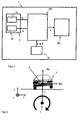
- a vehicle 1 comprises a device according to the invention for determining the roll angle for an occupant protection device 200 having a first acceleration sensor 10 for detecting a lateral acceleration a y , a second acceleration sensor 20 for detecting a high acceleration a z , a sensor unit 30 for determining further vehicle dynamics values, which is a vehicle speed v, a yaw angle ⁇ and a slip angle ⁇ include, and an evaluation unit 100, which the roll angle ⁇ of the vehicle based on the detected lateral acceleration a y and the detected high acceleration a z estimates and a centripetal acceleration ⁇ 2 r to improve the estimation of the roll angle ⁇ calculated from these driving dynamics variables.
- the first and second acceleration sensors 10, 20 are integrated into a central sensor system 2.
- the accelerations which a sensor in the center of gravity of the vehicle in the vicinity of the roll axis can measure, can be calculated in the evaluation unit 100 by a homogeneous transformation according to equation (1) from the outer acceleration acting on the vehicle in world coordinates.
- a ⁇ sensor X * a ⁇ Outside
- the outer acceleration vector is composed of an acceleration component in the x-direction, which is influenced for example by accelerating or braking the vehicle, a centripetal acceleration component in the y-direction, which occurs in particular during cornering or circular driving, and the gravitational acceleration component in the z-direction.
- a rotation of the vehicle about its longitudinal axis about a roll angle ⁇ can be represented by a multiplication of the outer acceleration vector with a 3 ⁇ 3 matrix according to equation (2).
- a ⁇ sensor 1 0 0 0 cos ⁇ - sin ⁇ 0 sin ⁇ cos ⁇ * - ⁇ ⁇ 2 r G
- the first acceleration sensor 10 detects only the lateral acceleration a y of the vehicle, ie the y component
- the second acceleration sensor 20 detects only the high acceleration a z of the vehicle, ie the z component, only the relationships (3 ) and (4) concerning the x components and the y component of the vehicle acceleration.
- a y cos ⁇ * ⁇ 2 r - sin ⁇ *
- This calculation method of the centripetal acceleration ⁇ 2 r responds particularly to slight fluctuations in the high acceleration a z very sensitively, which in turn leads to large fluctuations in the low roll angle range in the calculation of the roll angle according to equation (6)
- ⁇ - a y * G + a z * v 2 / r G 2 + v 2 / r 2 can lead.
- An improvement can be achieved by the fact that the centripetal acceleration ⁇ 2 r is not calculated with equation (5) but in an alternative way.
- FIG. 4 illustrates this with reference to a schematic representation of the course of various methods for roll angle estimation during a steep turn.
- the roll angle curve ⁇ R represents the course of the roll angle ⁇ determined by a reference sensor.
- the dotted angular variation ⁇ H represented by the equation (6) represents the course of the roll angle ⁇ calculated with the equation (6) when the centripetal acceleration ⁇ 2 r is determined by equation (5).
- the roll angle curve ⁇ E 1 shown in bold represents the course of the roll angle ⁇ calculated with the equation (6) when the centripetal acceleration ⁇ 2 r is determined by equation (7).
- the improved estimate of centripetal acceleration ⁇ 2 r According to equation (7) effected in the low roll angle range at the roll angle course ⁇ E1 significantly lower fluctuations than the roll angle curve ⁇ H with the recent estimate of the centripetal acceleration ⁇ 2 r according to equation (5).
- FIG. 2 a schematic representation of a model presentation of the relationships with small bumps in the road, which can cause additional roll.
- Correction quantities ⁇ a y1 , ⁇ a y2 , ⁇ a z for the high acceleration a z and the lateral acceleration a y can then be determined with the aid of the roll rate measured, for example, using a rotation rate sensor.
- the first acceleration sensor 10 for determining the lateral acceleration a y determined at a caused by the rolling motion change of the roll rate, a first additional tangential portion .DELTA.a y1 , which can be determined according to equation (8).
- ⁇ ⁇ a y ⁇ 1 ⁇ ⁇ x * r y
- the second acceleration sensor 20 for determining the high acceleration a z determines an additional centrifugal force component ⁇ a z , which can be determined according to equation (9), when the roll rate change is caused by the rolling motion.
- ⁇ ⁇ a z ⁇ x 2 * r z
- centripetal acceleration generated according to Equation 7 becomes ⁇ 2 r also adjusted.
- the effects of these rolling movements on the high acceleration a z and the lateral acceleration a y can be corrected.
- FIG. 3 a schematic representation of a model presentation of the relationships in a steering operation. How out FIG. 3 it can be seen, the central sensor 2 learns with the first acceleration sensor 10, which determines the lateral acceleration a y , an additional second tangential acceleration component and determines a second additional lateral acceleration component .DELTA.a y2 .
- the second acceleration sensor 20 for determining the high acceleration a z is not affected in a steering operation.
- FIG. 5 shows a schematic representation of the course of various methods for roll angle estimation during a steep turn with a steering movement when extending from the banked curve.
- the roll angle curve ⁇ R represents the course of the roll angle ⁇ determined by a reference sensor system.
- the dotted angular course ⁇ E1 represented by dots represents the profile of the roll angle ⁇ calculated with the equation (6) when the centripetal acceleration ⁇ 2 r is determined by equation (7).
- FIG. 6 shows a higher-resolution representation of the course of various methods for roll angle estimation Fig. 5 with an additional roll angle curve ⁇ E2 shown in bold, which represents the course of the roll angle ⁇ calculated with the equation (6), if the centripetal acceleration ⁇ 2 r is determined with Equation (7), and the lateral acceleration a y is calculated according to the equation (9), and the high acceleration a z is calculated according to the equation (10).
- FIG. 6 It can be seen that the deviations of the roll angle course ⁇ E1 from the reference course ⁇ R caused by the additional rolling and steering movements can be almost completely compensated for by the correction variables considered in the roll angle run ⁇ E2 .
- the roll angle estimation is more accurate in the higher angular range and the fluctuations due to the steering movement are almost completely compensated.
- the method according to the invention and the associated device enable accurate and robust roll angle determination by the use of the acceleration signals as well as the further driving dynamics signals of other sensor systems, whereby rollovers can be reliably detected. Therefore, the inventive method and the associated device for roll angle estimation can be used in the rollover detection, for example, as an alternative path and to support the roll angle calculation, or for plausibility of the triggering decision.
- the waiver of a roll rate sensor would further reduce the cost of the associated control unit, so that vehicle types can be equipped in the lower price segments with the control unit.
- the combination with already integrated in the vehicle sensor systems here is a Mehmutzen what stability and robustness of the triggering process affects. This is especially true in the field of all-terrain vehicles, as due to the vehicle design for the terrain compared to the normal road with respect to the robustness with increased demand on the triggering method for the detection of misuses is expected.
Abstract
Description
Die Erfindung geht aus von einem Verfahren zur Wankwinkelbestimmung für Insassenschutzvorrichtungen nach der Gattung des unabhängigen Patentanspruchs 1 und von einer zugehörigen Vorrichtung.The invention is based on a method for roll angle determination for occupant protection devices according to the preamble of
Zahlen aus den USA belegen die Bedeutung der passiven Sicherheit bei Fahrzeugüberschlägen. Im Jahr 1998 war die Hälfte aller tödlichen Einzelfahrzeugunfälle auf einen Überschlag zurückzuführen. Im gesamten Unfallgeschehen nimmt der Fahrzeugüberschlag einen Anteil von rund 20 Prozent ein.Figures from the US confirm the importance of passive safety in vehicle rollovers. In 1998, half of all fatal vehicle accidents were due to a rollover. In the entire accident scene, the vehicle rollover takes a share of about 20 percent.
Herkömmliche Systeme zur Überschlagserkennung betrachten die Wankbewegung und die Beschleunigungen in x-, y- und z-Richtung des Fahrzeugs. Auf dieser Basis ist eine sichere Erkennung eines Fahrzeugüberschlags möglich, wobei die Entscheidung, ob ein Überschlag vorliegt, jedoch erst zu einem späten Zeitpunkt des Überschlags sicher getroffen wird. Bei bestimmten Fällen von Fahrzeugüberschlägen, welchen ein fahrdynamisches Manöver vorausgeht, erfährt der Insasse hohe laterale Beschleunigungen. Derartige Manöver können beispielsweise zu so genannten Soil-Trip-Überschlägen führen. Diesbezüglich besteht hinsichtlich des Auslöseverhaltens noch Potential für zukünftige Insassenschutzsysteme.Conventional rollover detection systems look at the roll and accelerations in the x, y, and z directions of the vehicle. On this basis, a safe detection of a vehicle rollover is possible, the decision as to whether a rollover is present, however, is made only at a late date of rollover safely. In certain cases of vehicle rollovers, preceded by a dynamic maneuver, the occupant experiences high lateral accelerations. Such maneuvers can lead, for example, to so-called soil trip rollovers. In this regard, there is potential for future occupant protection systems in terms of tripping behavior.
Bekannte Verfahren beruhen beispielsweise auf der Auswertung eines Drehratensensors und zwei Beschleunigungssensoren, welche in einem zentralen Airbagsteuergerät integriert sind. Der Drehratensensor ermittelt nach dem Kreiselprinzip die Rotationsgeschwindigkeit um die Fahrzeuglängsachse und die Beschleunigungssensoren messen zusätzlich die Fahrzeugbeschleunigung in Quer- und Hochrichtung. Im Hauptalgorithmus wird dann die Drehrate ausgewertet. Mit den Messwerten der Beschleunigungssensoren lässt sich zum einen die Art des Überschlags erkennen, zum anderen dienen diese Werte der Plausibilitätsprüfung. Erkennt der Drehratenalgorithmus einen Überschlag, werden die Sicherheitsvorrichtungen nur bei gleichzeitiger Freigabe durch die Plausibilitätskontrolle aktiviert.Known methods are based, for example, on the evaluation of a rotation rate sensor and two acceleration sensors, which are integrated in a central airbag control unit. The rotation rate sensor determines the rotational speed about the vehicle longitudinal axis according to the gyroscope principle, and the acceleration sensors additionally measure the vehicle acceleration in the transverse and vertical directions. The rate of rotation is then evaluated in the main algorithm. With the measured values of the acceleration sensors, on the one hand, the type of rollover can be detected; on the other hand, these values are used for the plausibility check. If the rotation rate algorithm detects a rollover, the safety devices are only activated if they are enabled by the plausibility check.
Bei einem anderen bekannten Verfahren wird eine rechtzeitige Auslöseentscheidung bei Überschlägen mit hoher lateraler Beschleunigung dadurch ermöglicht, dass ein Schwimmwinkel und die laterale Geschwindigkeit des Fahrzeugs einbezogen werden. Bei einem bekannten Verfahren zur erweiterten Überrollerkennung wird aus einer Gierrate und der Fahrzeuggeschwindigkeit in longitudinaler Richtung unter Berücksichtigung der lateralen Beschleunigung eine Schätzung für die laterale Geschwindigkeit durchgeführt, welche beim seitlichen Abdriften in den Grünstreifen ein Maß für die Überrollwahrscheinlichkeit des Fahrzeugs darstellt. Zur Bestimmung der lateralen Geschwindigkeit wird ebenfalls der so genannte Schwimmwinkel herangezogen.In another known method, a timely trigger decision in high lateral acceleration rollovers is made possible by including a slip angle and the lateral speed of the vehicle. In a known method for extended rollover detection, an estimate for the lateral speed is performed from a yaw rate and the vehicle speed in the longitudinal direction taking into account the lateral acceleration, which is a measure of the rollover probability of the vehicle when drifting sideways into the green area. To determine the lateral velocity, the so-called float angle is also used.
Generell sind bei Überschlägen frühzeitige Auslöseentscheidungen für die Insassenschutzmittel, z.B. für Window-Airbags, sinnvoll und notwendig. Neben der lateralen Fahrzeuggeschwindigkeit stellt daher der Wankwinkel zu Beginn eines solchen Überschlagsvorganges eine wichtige Größe zur Vorausberechnung des Überschlagsgeschehens dar. Insbesondere spielt der Wankwinkel in Fällen von Auslöseentscheidungen für irreversible Insassenschutzmittel eine wichtige Rolle, wobei die Auslöseentscheidung in Kenntnis des Wankwinkels entsprechend früher erfolgen kann.Generally, in rollovers, early deployment decisions for the occupant protection means, e.g. for window airbags, useful and necessary. In addition to the lateral vehicle speed, therefore, the roll angle at the beginning of such a rollover process is an important parameter for the prediction of the rollover event. In particular, the roll angle plays an important role in cases of trigger decisions for irreversible occupant protection means, whereby the triggering decision with knowledge of the roll angle can take place correspondingly earlier.
Bei den bisher bekannten technischen Lösungen werden die Signale des Quer- und Hochbeschleunigungssensors lediglich zur Erkennung der Art des Überschlages und zur Plausibilisierung der mit einem Wankratensensor gemessenen Wankrate und des daraus berechneten Wankwinkels verwendet. So wird beispielsweise in der
Bei den bekannten Verfahren erfolgt die Schätzung des Wankwinkels nicht unabhängig von einem Wankratensensor, welcher idealerweise eine unabhängige Winkelschätzung durch zeitliche Aufintegration der Wankrate liefern sollte. Darüber hinaus ist die Bestimmung von sehr kleinen Wankwinkeln (< 5°) aufgrund von Sensorrauschen des Wankratensensors sehr schwierig.In the known methods, the estimation of the roll angle is not independent of a roll rate sensor, which ideally should provide an independent angle estimate by temporal integration of the roll rate. In addition, the determination of very small roll angles (<5 °) due to sensor noise of the roll rate sensor is very difficult.
Ein derartiges Verfahren ist aus der
Das erfindungsgemäße Verfahren zur Wankwinkelbestimmung für Insassenschutzvorrichtungen mit den Merkmalen des unabhängigen Patentanspruchs 1 hat demgegenüber den Vorteil, dass der Wankwinkel unabhängig von einem Wankratensensor und ohne Einschränkung des Wankwinkelbereichs mit Hilfe der Signale eines Querbeschleunigungssensors und eines Hochbeschleunigungssensors kontinuierlich geschätzt werden kann und beispielsweise zu einem frühen Zeitpunkt mindestens einem Auslöseverfahren für Insassenschutzmittel zur Verfügung gestellt werden kann. Durch das erfindungsgemäße Verfahren werden zur Berechung der Zentripetalbeschleunigung weitere Fahrdynamikgrößen ermittelt, welche eine Fahrzeuggeschwindigkeit, einen Gierwinkel und einen Schwimmwinkel umfassen, wodurch die Schätzung des Wankwinkels in vorteilhafter Weise verbessert wird. Diese zusätzlichen Fahrdynamiksensordaten können beispielsweise von anderen Sensoreinheiten im Fahrzeug, z.B. von einem elektronischen Stabilitätsprogrammiersystem (ESP-System), zur Verfügung gestellt werden. Insgesamt ergibt sich durch das erfindungsgemäße Verfahren in vorteilhafter Weise eine genauere und stabilere direkte Wankwinkelschätzung, dies gilt insbesondere im Bereich kleiner Wankwinkel. Durch den bereitgestellten genaueren und stabileren Wankwinkel können nachfolgende Auslöseverfahren für Insassenschutzsysteme Fahrzeugüberschläge frühzeitig erkennen, wodurch gewährleistet werden kann, dass Sicherheitsvorrichtungen wie Gurtstraffer, Kopfairbag, Window-Airbag und Überrollbügel rechtzeitig aktiviert werden und sich somit das Verletzungsrisiko für die Insassen verringert. Somit ermöglicht das erfindungsgemäße Verfahren zur Wankwinkelbestimmung in vorteilhafter Weise eine Verbesserung der Berechnung von Auslöseentscheidungen für Insassenschutzsysteme.The inventive method for roll angle determination for occupant protection devices with the features of
Als weiteren Vorteil erhöht das erfindungsgemäße Verfahren zur Wankwinkelbestimmung, insbesondere im Bereich von kleinen Wankwinkeln, die Robustheit der nachgeschalteten Auslöseverfahren und verbessert deren Rücksetzverhalten. Dadurch können in vorteilhafter Weise eine verbesserte Auslöseleistungsfähigkeit erreicht, stabile Fahrsituationen und Misuses besser erkannt und eine versehentliche Auslösung von irreversiblen Rückhaltemitteln verhindert werden. Die Kombination mit schon im Fahrzeug integrierten Sensorsystemen ergibt hier einen Mehrnutzen was Stabilität und Robustheit des Auslöseverfahrens betrifft, wodurch insbesondere die Überschlagsdetektierung bei geländegängigen Fahrzeugen aufgrund des sehr robusten Auslöseverfahrens verbessert werden kann. Aufgrund der Fahrzeugauslegung für das Gelände, ist im Vergleich zum normalen Straßenverkehr bezüglich der Robustheit mit einer gesteigerten Anforderung an das Auslöseverfahren zur Erkennung von Misuses zu rechnen.As a further advantage, the inventive method for roll angle determination, in particular in the range of small roll angles, increases the robustness of the downstream triggering methods and improves their reset behavior. As a result, improved triggering power can be achieved in an advantageous manner, stable driving situations and misuses can be better recognized and accidental triggering of irreversible restraining means prevented. The combination with already integrated in the vehicle sensor systems gives here an added benefit stability and robustness of the triggering process, which in particular the rollover detection in off-road vehicles due to the very robust release process can be improved. Due to the design of the vehicle for the terrain, increased robustness requirements compared to normal road traffic can be expected in the detection of misuse detection.
Zudem kann das erfindungsgemäße Verfahren zur Schätzung des Wankwinkels zusätzlich zu einem Wankratensensor eingesetzt werden, um in vorteilhafter Weise als alternativer Pfad die Wankwinkelschätzung über den Wankratensensor zu stützen bzw. zur Plausibilisierung der Auslöseentscheidung eingesetzt zu werden. Daher werden durch die zusätzliche Möglichkeit der Wankwinkelbestimmung das Auslöseverhalten und das Rücksetzverhalten der Auslöseverfahren für Insassenschutzsysteme weiter verbessert.In addition, the method according to the invention for estimating the roll angle can be used in addition to a roll rate sensor in order to advantageously support the roll angle estimation via the roll rate sensor as an alternative path or to use it for plausibility of the triggering decision. Therefore, the additional possibility of Wankwinkelbestimmung the tripping behavior and the reset behavior of the deployment methods for occupant protection systems further improved.
Die erfindungsgemäße Vorrichtung zur Wankwinkelbestimmung für Insassenschutzvorrichtungen mit den Merkmalen des unabhängigen Patentanspruchs 10 hat den Vorteil, dass zwei Beschleunigungssensoren zur Erfassung der Querbeschleunigung und zur Erfassung der Hochbeschleunigung verwendet werden und eine Auswerteeinheit basierend auf der erfassten Querbeschleunigung und der erfassten Hochbeschleunigung den Wankwinkel des Fahrzeugs schätzt, so dass auf einen Wankwinkelsensor verzichtet werden kann. Zur Verbesserung der Schätzung des Wankwinkels wertet die Auswerteeinheit Daten von mindestens einer weiteren Sensoreinheit im Fahrzeug aus, welche weitere Fahrdynamikdaten ermittelt und für eine Berechnung einer Zentripetalbeschleunigung bereitstellt. Die Fahrdynamikdaten umfassen eine Fahrzeuggeschwindigkeit, einen Gierwinkel und einen Schwimmwinkel. Da ein Wankratensensor zur Abschätzung des Wankwinkels nicht mehr erforderlich ist, können durch den Verzicht auf den Wankratensensor die Kosten für das zugehörige Steuergerät gesenkt werden. Wird die erfindungsgemäße Vorrichtung als alternativer Pfad und zur Stützung der Wankwinkelberechnung durch den Wankratensensor eingesetzt, dann stehen in vorteilhafter Weise zwei alternative Pfade zur Wankwinkelbestimmung zur Verfügung, wodurch die Robustheit der Auslöseverfahren für Insassenschutzvorrichtungen erhöht werden kann.The inventive device for roll angle determination for occupant protection devices with the features of
Durch die in den abhängigen Ansprüchen aufgeführten Maßnahmen und Weiterbildungen sind vorteilhafte Verbesserungen des im unabhängigen Patentanspruch angegebenen Verfahrens zur Wankwinkelbestimmung für Insassenschutzvornchtungen möglich.The measures and refinements recited in the dependent claims, advantageous improvements of the method specified in the independent claim for roll angle determination for occupant protection devices are possible.
Besonders vorteilhaft ist, dass durch Lenkbewegungen verursachte Beschleunigungen und/oder durch Fahrbahnunebenheiten verursachte Wankbewegungen bestimmt und als Korrekturgrößen bei der Ermittlung der aktuellen Querbeschleunigung und der aktuellen Hochbeschleunigung und somit bei der Schätzung des Wankwinkels berücksichtigt werden. Um Korrekturgrößen für die Wankbewegung zu berechnen wird angenommen, dass sich die Wankbewegungen in erster Näherung als eine Rotation der Zentralsensorik um einen fiktiven Drehpunkt betrachten lassen. Der Hochbeschleunigungssensor "sieht" dann einen zusätzlichen "Fliehkraftanteil" und der Querbeschleunigungssensor erkennt bei einer Änderung der Wankrate einen zusätzlichen tangentialen Anteil. Mit der gemessenen Wankrate können dann Korrekturgrößen für die Hochbeschleunigung und die Querbeschleunigung bestimmt werden. So kann zum Ausgleich der Fahrbahnunebenheiten beispielsweise ein erster zusätzlicher Querbeschleunigungsanteil und ein zusätzlicher Hochbeschleunigungsanteil als Korrekturgrößen berechnet werden. Der erste zusätzliche Querbeschleunigungsanteil Δay1 kann beispielsweise nach der Gleichung Δay1 = ω̇x *rz berechnet werden und der zusätzliche Hochbeschleunigungsanteil Δaz kann beispielsweise nach der Gleichung ![]()
![]()
Um Korrekturgrößen für die Lenkbewegung zu berechnen wird angenommen, dass eine Lenkbewegung während einer normalen Fahrsituation einen Drehpunkt in der Nähe der Hinterachse aufweist, daher erfährt der Querbeschleunigungssensor eine zusätzliche tangentiale Beschleunigungskomponente, welche als zweiter zusätzlicher Querbeschleunigungsanteil berechnet wird. Der Hochbeschleunigungssensor ist bei einem Lenkvorgang nicht betroffen. Ein Sensor in x-Richtung, der zusätzliche Fliehkräfte erfahren würde, wird in dieser Betrachtung nicht berücksichtigt. Der zweite zusätzliche Querbeschleunigungsanteil Δay2 kann beispielsweise nach der Gleichung Δay2 =ω̇z *rx berechnet werden.In order to calculate correction quantities for the steering movement, it is assumed that a steering movement during a normal driving situation has a pivot point in the vicinity of the rear axle, therefore the lateral acceleration sensor receives an additional tangential acceleration component, which is calculated as a second additional lateral acceleration component. The high acceleration sensor is not affected in a steering operation. A sensor in the x-direction, which would experience additional centrifugal forces, is not considered in this consideration. The second additional lateral acceleration component .DELTA.a y2 can be calculated, for example, according to the equation y2 = .DELTA.a w z * r x.
Das erfindungsgemäße Verfahren und die erfindungsgemäße Vorrichtung zur Wankwinkelbestimmung für Insassenschutzvorrichtungen zeigen das hohe Verbesserungspotential bei der direkten Wankwinkelberechnung, wenn zusätzliche Sensorinformationen genutzt werden, um die gemessenen Werte der Zentralsensorik über Korrekturgrößen zu verbessern und um Größen des Gleichungssystems zur Wankwinkelberechnung, wie die Zentripetalbeschleunigung, alternativ zu berechnen. So wird die Genauigkeit der Wankwinkelschätzung, insbesondere bei kleinen Wankwinkelwerten und bei während der Fahrt über Unebenheiten auftretenden Schwingungen der Fahrzeugfedersysteme oder bei aktiven Lenkbewegungen des Fahrers verbessert. Darüber hinaus wird die Genauigkeit der über zusätzliche Sensordaten abgeschätzten Zentripetalbeschleunigung im unteren Wankwinkelbereich verbessert, wodurch die Schwankungen des geschätzten Absolutwankwinkels reduziert werden können.The method according to the invention and the roll angle determination device according to the invention for occupant protection devices show the high potential for improvement in the direct roll angle calculation if additional sensor information is used to improve the measured values of the central sensor system via correction quantities and sizes of the roll angle calculation system such as the centripetal acceleration, as an alternative to calculate. Thus, the accuracy of the roll angle estimation, especially for small roll angle values and when occurring during driving over bumps oscillations of the vehicle spring systems or active steering movements of the driver is improved. In addition, the accuracy of the centripetal acceleration estimated via additional sensor data in the lower roll angle range is improved, whereby the fluctuations of the estimated absolute roll angle can be reduced.
Ausführungsbeispiele der Erfindung sind in der Zeichnung dargestellt und werden in der nachfolgenden Beschreibung näher erläutert.Embodiments of the invention are illustrated in the drawings and are explained in more detail in the following description.
Es zeigen:
Figur 1- ein schematisches Blockdiagramm einer Vorrichtung zur Wankwinkelbestimmung für In- sassenschutzvorrichtungen,
Figur 2- eine schematische Darstellung einer Modellvorstellung der Zusammenhänge bei kleinen Unebenheiten der Fahrbahn,
Figur 3- eine schematische Darstellung einer Modellvorstellung der Zusammenhänge bei einer Lenkbewegung,
Figur 4- eine schematische Darstellung des Verlaufs von verschiedenen Verfahren zur Wankwinkel- schätzung während einer Steilkurvenfahrt,
- Figur 5
- eine schematische Darstellung des Verlaufs von verschiedenen Verfahren zur Wankwinkel- schätzung während einer Steilkurvenfahrt mit einer Lenkbewegung beim Ausfahren aus der Steilkurve, und
Figur 6- eine höher aufgelöste Darstellung des Verlaufs von verschiedenen Verfahren zur Wank- winkelschätzung aus
Fig. 5 .
- FIG. 1
- 2 is a schematic block diagram of a device for determining roll angle for occupant protection devices,
- FIG. 2
- a schematic representation of a model presentation of the relationships with small bumps in the road,
- FIG. 3
- a schematic representation of a model presentation of the relationships in a steering movement,
- FIG. 4
- a schematic representation of the course of various methods for roll angle estimation during a steep turn,
- FIG. 5
- a schematic representation of the course of various methods for Wankwinkel- estimate during a steep turning with a steering movement when extending from the banked curve, and
- FIG. 6
- a higher-resolution representation of the course of various methods for roll angle estimation
Fig. 5 ,
Generell sind bei Überschlägen frühzeitige Auslöseentscheidungen für die Insassenschutzmittel, z.B. für Gurtstraffer, Kopfairbag, Window-Airbag und Überrollbügel, sinnvoll und notwendig. Neben der lateralen Fahrzeuggeschwindigkeit stellt daher der Wankwinkel zu Beginn eines solchen Überschlagsvorganges eine wichtige Größe zur Vorausberechnung des Überschlagsgeschehens dar. Bei den bisher bekannten technischen Lösungen werden die Signale des Quer- und Hochbeschleunigungssensors lediglich zur Erkennung der Art des Überschlages und zur Plausibilisierung der mit einem Wankratensensor gemessenen Wankrate und des daraus berechneten Wankwinkels verwendet.Generally, in rollovers, early deployment decisions for the occupant protection means, e.g. for belt tensioners, head airbags, window airbags and roll bars, useful and necessary. In addition to the lateral vehicle speed, therefore, the roll angle at the beginning of such a rollover process is an important parameter for the prediction of the rollover event. In the hitherto known technical solutions, the signals of the lateral and high acceleration sensor are only for detecting the type of rollover and for plausibility checking with a roll rate sensor measured roll rate and calculated therefrom roll angle used.
Zudem ist in einer älteren Anmeldung der Anmelderin ein Verfahren zur kontinuierlichen Berechnung des absoluten Fahrzeugwankwinkels mit Hilfe der Signale eines Querbeschleunigungssensors und eines Hochbeschleunigungssensors während stabiler Fahrsituationen als Ausgangswankwinkel zur Verbesserung der Berechnung von Auslöseentscheidungen in entsprechenden Untermodulen eines Insassenschutzsystems beschrieben.In addition, in an earlier application of the applicant, a method for continuously calculating the absolute vehicle roll angle by means of the signals of a lateral acceleration sensor and a high acceleration sensor during stable driving situations as output roll angle for improving the calculation of trigger decisions in corresponding sub-modules of an occupant protection system is described.
Erfindungsgemäß wird ein Verfahren zur Wankwinkelbestimmung für Insassenschutzvorrichtungen und eine zugehörige Vorrichtung vorgeschlagen, welche eine Querbeschleunigung und eine Hochbeschleunigung des Fahrzeugs erfassen und den Wankwinkel des Fahrzeug basierend auf der erfassten Querbeschleunigung und der erfassten Hochbeschleunigung schätzten, wobei weitere Fahrdynamikgrößen ermittelt werden, welche eine Fahrzeuggeschwindigkeit, einen Gierwinkel und einen Schwimmwinkel umfassen, und wobei eine Zentripetalbeschleunigung zur Verbesserung der Schätzung des Wankwinkels aus diesen Fahrdynamikgrößen berechnet wird.According to the invention, a method for roll angle determination for occupant protection devices and an associated device is proposed, which detect a lateral acceleration and a high acceleration of the vehicle and estimated the roll angle of the vehicle based on the detected lateral acceleration and the detected high acceleration, wherein further vehicle dynamics variables are determined, which a vehicle speed, a Yaw angle and a slip angle, and wherein a centripetal acceleration is calculated to improve the estimate of the roll angle from these vehicle dynamics quantities.
Wie aus ![]()
![]()
Nachfolgend werden die mathematischen Grundlagen und die daraus abgeleiteten Gleichungen beschrieben, welche die Auswerteeinheit 100 zur kontinuierlichen Bestimmung des aktuellen Wankwinkels benutzt. Die Beschleunigungen, welche ein Sensor im Fahrzeugschwerpunkt in der Nähe der Wankachse messen kann, lassen sich in der Auswerteeinheit 100 durch eine homogene Transformation gemäß Gleichung (1) aus den äußeren am Fahrzeug angreifenden Beschleunigungen in Weltkoordinaten berechnen. ![]()
![]()
Der äußere Beschleunigungsvektor setzt sich aus einer Beschleunigungskomponente in x-Richtung, welche beispielsweise durch Gas geben oder Bremsen des Fahrzeugs beeinflusst wird, einer Zentripetalbeschleunigungskomponente in y-Richtung, welche insbesondere bei Kurvenfahrten oder bei Kreisfahrten auftritt, sowie der Erdbeschleunigungskomponente in z-Richtung zusammen. Eine Drehung des Fahrzeugs um seine Längsachse um einen Wankwinkel α lässt sich durch eine Multiplikation des äußeren Beschleunigungsvektors mit einer 3x3-Matrix gemäß Gleichung (2) darstellen. 
Da der erste Beschleunigungssensor 10 nur die Querbeschleunigung ay des Fahrzeugs erfasst, d.h. die y-Komponente, und der zweite Beschleunigungssensor 20 nur die Hochbeschleunigung az des Fahrzeugs erfasst, d.h. die z-Komponente, werden nach der Matrixmultiplikation nachfolgend nur die Zusammenhänge (3) und (4) betrachtet, welche die x-Komponenten und die y-Komponente der Fahrzeugbeschleunigung betreffen. ![]()
![]()
![]()
![]()
In den Gleichungen (3) und (4) sind neben dem Wankwinkel α auch noch die Zentripetalbeschleunigung ![]()
![]()
![]()
![]()
![]()
![]()
![]()
![]()
![]()
![]()
Diese Berechnungsart der Zentripetalbeschleunigung ![]()

![]()
![]()
![]()
![]()
![]()
![]()
![]()
![]()
![]()
![]()
![]()
![]()
![]()
![]()
![]()
Durch Lenkbewegungen und Unebenheiten der Fahrbahn entstehen kleine Wankbewegungen des Fahrzeugs 1. Um Korrekturgrößen für durch Fahrbahnunebenheiten verursachte Wankbewegungen zu berechnen, welche die Schätzung der direkten Wankwinkelwerte verfälschen können, wird angenommen, dass sich die Wankbewegungen in erster Näherung als eine Rotation der Zentralsensorik 2 um einen fiktiven Drehpunkt 3 betrachten lassen. Daher zeigt ![]()
![]()
Der zweite Beschleunigungssensor 20 zur Ermittlung der Hochbeschleunigung az ermittelt bei einer durch die Wankbewegung verursachte Änderung der Wankrate einen zusätzlichen Fliehkraftanteil Δaz, welcher gemäß Gleichung (9) bestimmt werden kann. ![]()
![]()
Zudem wird die gemäß Gleichung 7 erzeugte Zentripetalbeschleunigung ![]()
![]()
Durch die Bestimmung des ersten zusätzlichen Querbeschleunigungsanteils Δay1 und des zusätzliches Hochbeschleunigungsanteils Δaz können die Auswirkungen dieser Wankbewegungen auf die Hochbeschleunigung az und die Querbeschleunigung ay korrigiert werden.By determining the first additional lateral acceleration component Δa y1 and the additional high acceleration component Δa z , the effects of these rolling movements on the high acceleration a z and the lateral acceleration a y can be corrected.
Ähnlich verhält es sich bei Lenkbewegungen des Fahrers. Um Korrekturgrößen für durch Lenkbewegungen verursachte Wankbewegungen zu berechnen, welche die Schätzung der direkten Wankwinkelwerte verfälschen können, wird angenommen, dass sich ein Lenkvorgang als eine Rotation der Zentralsensorik 2 um einen fiktiven Drehpunkt 4 betrachten lässt, welcher während einer normalen Fahrsituation in der Nähe der Hinterachse angeordnet ist. Daher zeigt ![]()
![]()
![]()
![]()
Der zweite Beschleunigungssensor 20 zur Ermittlung der Hochbeschleunigung az ist bei einem Lenkvorgang nicht betroffen. Ein Sensor in x-Richtung, welcher zusätzliche Fliehkräfte erfahren würde, wird in dieser Betrachtung nicht berücksichtigt.The
Kombiniert man die Gleichungen (3) und (4) mit den Korrekturen gemäß den Gleichungen (8), (9) und (10), dann ergibt sich ein neues Gleichungssystem mit den Gleichungen (11) und (12): ![]()
![]()
![]()
![]()
![]()
![]()
![]()
![]()
![]()
![]()
Das erfindungsgemäße Verfahren und die zugehörige Vorrichtung ermöglichen durch die Nutzung der Beschleunigungssignale, sowie der weiteren Fahrdynamiksignale anderer Sensorsysteme eine genaue und robuste Wankwinkelbestimmung, wodurch Überschläge sicher erkannt werden können. Deshalb können das erfindungsgemäße Verfahren und die zugehörige Vorrichtung zur Wankwinkelschätzung bei der Überschlagserkennung eingesetzt werden, beispielsweise als alternativer Pfad und zur Stützung der Wankwinkelberechnung, bzw. zur Plausibilisierung der Auslöseentscheidung. Der Verzicht auf einen Wankratensensor würde die Kosten für das zugehörige Steuergerät weiter senken, so dass auch Fahrzeugtypen in den unteren Preissegmenten mit dem Steuergerät ausgerüstet werden können. Die Kombination mit schon im Fahrzeug integrierten Sensorsystemen ergibt hier einen Mehmutzen was Stabilität und Robustheit des Auslöseverfahrens betrifft. Dies gilt insbesondere im Bereich von geländegängigen Fahrzeugen, da aufgrund der Fahrzeugauslegung für das Gelände im Vergleich zum normalen Straßenverkehr bezüglich der Robustheit mit einer gesteigerten Anforderung an das Auslöseverfahren zur Erkennung von Misuses zu rechnen ist.The method according to the invention and the associated device enable accurate and robust roll angle determination by the use of the acceleration signals as well as the further driving dynamics signals of other sensor systems, whereby rollovers can be reliably detected. Therefore, the inventive method and the associated device for roll angle estimation can be used in the rollover detection, for example, as an alternative path and to support the roll angle calculation, or for plausibility of the triggering decision. The waiver of a roll rate sensor would further reduce the cost of the associated control unit, so that vehicle types can be equipped in the lower price segments with the control unit. The combination with already integrated in the vehicle sensor systems here is a Mehmutzen what stability and robustness of the triggering process affects. This is especially true in the field of all-terrain vehicles, as due to the vehicle design for the terrain compared to the normal road with respect to the robustness with increased demand on the triggering method for the detection of misuses is expected.
Claims (10)
- Method for determining the roll angle for occupant protection apparatuses, in which- a lateral acceleration (ay) and- a vertical acceleration (az) of the vehicle are acquired, and- the roll angle (α) of the vehicle is estimated on the basis of the acquired lateral acceleration (ay) and the acquired vertical acceleration (az),- with further vehicle dynamic variables being determined, which comprise a vehicle speed (v), a yaw angle (Ψ) and an attitude angle (β),characterized in that a centripetal acceleration

- Method according to Claim 1, characterized in that accelerations caused by steering movements and/or rolling movements caused by unevennesses of the roadway are determined and are taken into account as correction variables (Δay1, Δay2, Δaz) when determining the current lateral acceleration (ay) and the current vertical direction (az), and thus when estimating the roll angle (α).
- Method according to Claim 2, characterized in that the rolling movement caused by unevennesses of the roadway is regarded in the normal driving state as a rotation about an imaginary pivot point (3) and is calculated as first additional lateral acceleration component (Δay1) and as additional vertical acceleration component (Δaz).
- Method according to Claim 3, characterized in that the first additional lateral acceleration component (Δay1) is calculated using the equation Δay1 = ω̇x*rz, and the additional lateral acceleration component (Δaz) is calculated using the equation Δaz = ωx2*rz.
- Method according to one of Claims 2 to 4, characterized in that a steering movement during a normal driving situation has a pivot point (4) in the vicinity of the rear axle whose caused acceleration is calculated as second additional lateral acceleration component (Δay2).
- Method according to Claim 5, characterized in that the second additional lateral acceleration component (Δay2) is calculated using the equation Δay2 = ω̇z*rx.
- Method according to one of Claims 1 to 6, characterized in that the centripetal acceleration


- Method according to Claim 7, characterized in that the current lateral acceleration (ay) is calculated using the equation ay = cos α*v2/r-sin α*g + Δay1 + Δay2, and the current vertical acceleration (az) is calculated using the equation az = sin α*v2/r + cos α*g + Δaz.
- Method according to one of Claims 1 to 8, characterized in that the roll angle (α) is estimated in accordance with the equation

- Apparatus for determining the roll angle for occupant protection apparatuses for the purpose of carrying out the method according to one of Claims 1 to 9, comprising- a first acceleration sensor (10) for acquiring a lateral acceleration (ay) of a vehicle,- a second acceleration sensor (20) for acquiring a vertical acceleration (az) of the vehicle,- at least one further sensor unit (30), which determines and provides further vehicle dynamic variables which comprise a vehicle speed (v), a yaw angle (ψ) and an attitude angle (β), and- an evaluation unit (100) which estimates the roll angle (α) of the vehicle on the basis of the acquired lateral acceleration (ay) and the acquired vertical acceleration (az),characterized in that the evaluation unit (100) improves the estimate of the roll angle by calculating a centrifugal acceleration

Applications Claiming Priority (2)
| Application Number | Priority Date | Filing Date | Title |
|---|---|---|---|
| DE102005052251A DE102005052251A1 (en) | 2005-11-02 | 2005-11-02 | Passenger protection roll determination procedure records transverse and height acceleration and uses them with further dynamic values and centripetal acceleration calculation to estimate vehicle roll angle |
| PCT/EP2006/066723 WO2007051672A1 (en) | 2005-11-02 | 2006-09-26 | Method and apparatus for detemrining a roll angle for occupant protection apparatuses |
Publications (2)
| Publication Number | Publication Date |
|---|---|
| EP1945483A1 EP1945483A1 (en) | 2008-07-23 |
| EP1945483B1 true EP1945483B1 (en) | 2009-04-01 |
Family
ID=37575170
Family Applications (1)
| Application Number | Title | Priority Date | Filing Date |
|---|---|---|---|
| EP06806815A Expired - Fee Related EP1945483B1 (en) | 2005-11-02 | 2006-09-26 | Method and apparatus for detemrining a roll angle for occupant protection apparatuses |
Country Status (7)
| Country | Link |
|---|---|
| US (1) | US8185271B2 (en) |
| EP (1) | EP1945483B1 (en) |
| JP (1) | JP4878370B2 (en) |
| KR (1) | KR101011532B1 (en) |
| DE (2) | DE102005052251A1 (en) |
| ES (1) | ES2321877T3 (en) |
| WO (1) | WO2007051672A1 (en) |
Families Citing this family (15)
| Publication number | Priority date | Publication date | Assignee | Title |
|---|---|---|---|---|
| DE102005054127A1 (en) * | 2005-11-14 | 2007-05-16 | Bosch Gmbh Robert | Method and device for controlling personal protective equipment in a rollover process |
| SE532317C2 (en) * | 2007-07-05 | 2009-12-15 | Svenska Utvecklings Entrepreno | Device for waking up drivers and operators |
| US7996132B2 (en) | 2007-11-29 | 2011-08-09 | Robert Bosch Gmbh | Fast sensing system and method for soil- and curb-tripped vehicle rollovers |
| JP5181836B2 (en) * | 2008-05-27 | 2013-04-10 | 日本精工株式会社 | Roll angle estimation device and electric power steering device |
| US8398277B2 (en) * | 2010-03-05 | 2013-03-19 | Billie Brandt Fritz | Vehicle lighting system |
| US8902055B2 (en) * | 2011-06-08 | 2014-12-02 | Msi Defense Solutions, Llc | Rollover warning system for a vehicle |
| DE102011115374A1 (en) * | 2011-10-10 | 2013-04-11 | Continental Automotive Gmbh | Method for rollover detection of vehicle e.g. motor vehicle, involves determining transverse velocity of vehicle, and predicting staggering rate and staggering angle from transverse velocity discharge time and lateral acceleration |
| JP5626600B2 (en) * | 2012-03-21 | 2014-11-19 | 株式会社デンソー | Vehicle rollover detection device |
| DE102012209737A1 (en) * | 2012-06-11 | 2013-12-12 | Robert Bosch Gmbh | Method and control device for controlling a safety device for a vehicle in a rollover situation |
| DE102013208686B4 (en) * | 2013-05-13 | 2024-02-08 | Robert Bosch Gmbh | Device for controlling personal protection devices in a vehicle |
| JP6042308B2 (en) * | 2013-10-29 | 2016-12-14 | 本田技研工業株式会社 | Vehicle collision determination device |
| US9168950B1 (en) * | 2014-09-19 | 2015-10-27 | Robert Bosch Gmbh | Banked curve detection using vertical and lateral acceleration |
| JP6378082B2 (en) * | 2014-12-26 | 2018-08-22 | 株式会社Subaru | Vehicle control apparatus and vehicle control method |
| CN109070898B (en) * | 2016-03-04 | 2022-01-25 | 大陆-特韦斯股份有限公司 | Method for determining the roll angle of a motorcycle |
| JP6628702B2 (en) * | 2016-08-08 | 2020-01-15 | 日立オートモティブシステムズ株式会社 | Vehicle state quantity estimation device |
Family Cites Families (19)
| Publication number | Priority date | Publication date | Assignee | Title |
|---|---|---|---|---|
| JPH06227228A (en) | 1993-02-03 | 1994-08-16 | Nippondenso Co Ltd | Suspension control device |
| DE19736328A1 (en) * | 1997-08-21 | 1999-02-25 | Bayerische Motoren Werke Ag | Controlling accident protection triggering devices in motor vehicle |
| DE19744083A1 (en) | 1997-10-06 | 1999-04-08 | Bosch Gmbh Robert | Arrangement for producing trigger signal for safety unit in vehicle with roll operation |
| US6002974A (en) * | 1998-02-06 | 1999-12-14 | Delco Electronics Corporation | Vehicle rollover sensing using extended kalman filter |
| DE19814154A1 (en) * | 1998-03-30 | 1999-10-14 | Siemens Ag | Device and method for triggering an occupant protection system in the event of a vehicle rollover |
| JP4468509B2 (en) | 1999-04-06 | 2010-05-26 | 本田技研工業株式会社 | Vehicle steering system |
| US6170594B1 (en) * | 1999-06-01 | 2001-01-09 | Micky G. Gilbert | Method and apparatus for reducing vehicle rollover |
| DE59910473D1 (en) * | 1999-12-16 | 2004-10-14 | Siemens Ag | METHOD AND DEVICE FOR DETERMINING THE ABSOLUTE TURNING ANGLE OF AN OBJECT TURNING ANOTHER LEVEL |
| DE19962687C2 (en) * | 1999-12-23 | 2002-04-18 | Siemens Ag | Method and system for determining the angular acceleration of a body rotating about a predetermined axis of rotation, in particular of a motor vehicle rotating about its longitudinal axis |
| DE60022737T8 (en) * | 2000-04-17 | 2006-06-08 | Robert Bosch Gmbh | Apparatus and method for determining vehicle operating and dynamics parameters |
| DE10122654A1 (en) * | 2001-05-10 | 2002-12-05 | Bosch Gmbh Robert | Method and system for regulating the driving behavior of a vehicle |
| US6560519B2 (en) * | 2001-06-28 | 2003-05-06 | Robert Bosch Corporation | Rollover-sensing system for a vehicle and method of operating the same |
| WO2003026933A1 (en) * | 2001-08-31 | 2003-04-03 | Siemens Aktiengesellschaft | Control unit for an occupant protection system of a vehicle and method for processing signals of a rotation rate sensor in an occupant protection system |
| WO2003081180A2 (en) * | 2002-03-19 | 2003-10-02 | Automotive Systems Laboratory, Inc. | Vehicle rollover detection system |
| US7162340B2 (en) * | 2004-01-08 | 2007-01-09 | Delphi Technologies, Inc. | Vehicle rollover detection and method of anticipating vehicle rollover |
| US7031816B2 (en) * | 2004-03-23 | 2006-04-18 | Continental Teves, Inc. | Active rollover protection |
| DE102005011243A1 (en) * | 2005-03-11 | 2006-09-21 | Robert Bosch Gmbh | Method and device for roll angle determination for occupant protection devices |
| JP2007076584A (en) | 2005-09-16 | 2007-03-29 | Toyota Motor Corp | Vehicular steering control device |
| DE102005044763B4 (en) * | 2005-09-20 | 2017-09-28 | Robert Bosch Gmbh | Method and device for triggering personal protection devices in a rollover process |
-
2005
- 2005-11-02 DE DE102005052251A patent/DE102005052251A1/en not_active Withdrawn
-
2006
- 2006-09-26 WO PCT/EP2006/066723 patent/WO2007051672A1/en active Application Filing
- 2006-09-26 EP EP06806815A patent/EP1945483B1/en not_active Expired - Fee Related
- 2006-09-26 US US11/989,883 patent/US8185271B2/en active Active
- 2006-09-26 DE DE502006003351T patent/DE502006003351D1/en active Active
- 2006-09-26 ES ES06806815T patent/ES2321877T3/en active Active
- 2006-09-26 KR KR1020087010482A patent/KR101011532B1/en not_active IP Right Cessation
- 2006-09-26 JP JP2008538312A patent/JP4878370B2/en not_active Expired - Fee Related
Also Published As
| Publication number | Publication date |
|---|---|
| DE502006003351D1 (en) | 2009-05-14 |
| US8185271B2 (en) | 2012-05-22 |
| WO2007051672A1 (en) | 2007-05-10 |
| JP4878370B2 (en) | 2012-02-15 |
| KR20080064850A (en) | 2008-07-09 |
| EP1945483A1 (en) | 2008-07-23 |
| JP2009514721A (en) | 2009-04-09 |
| US20110082614A1 (en) | 2011-04-07 |
| DE102005052251A1 (en) | 2007-05-03 |
| ES2321877T3 (en) | 2009-06-12 |
| KR101011532B1 (en) | 2011-01-27 |
Similar Documents
| Publication | Publication Date | Title |
|---|---|---|
| EP1945483B1 (en) | Method and apparatus for detemrining a roll angle for occupant protection apparatuses | |
| EP1846269B1 (en) | Triggering method for activating a lateral speed estimation for passenger protection devices | |
| EP1157898B1 (en) | Method for rollover detection of vehicles with safety system | |
| DE60217741T2 (en) | Rollover detection system for motor vehicles | |
| DE102005042252B4 (en) | Rollover detection apparatus and method for vehicles | |
| EP2229293B1 (en) | Method and device for actuating safety means for for a vehicle | |
| EP2010415B1 (en) | Device and method for actuating passenger protection systems considering the road grip coefficient | |
| EP2318224B1 (en) | Method and device for preventing the lateral overturning of motor vehicles | |
| DE102013200459A1 (en) | VEHICLE ROLLOVER REDUCTION SYSTEM | |
| EP1599364B1 (en) | Method and device for determining the probability of an accident for a vehicle | |
| EP1861292B1 (en) | Method and device for determining the rolling angle for passenger protection devices | |
| DE102005037961A1 (en) | Method for recognition of side impact location on vehicle, wherein after side impact, first and second information relating to front side region and second side region of vehicle respectively are determined | |
| EP2454125B1 (en) | Rollover determination method. | |
| EP1536986B1 (en) | Device for recognizing a vehicle overturn | |
| EP1855918B1 (en) | Method and device for determining an initial attitude angle in order to detect swerving during overroll detection | |
| EP1724160A1 (en) | Method and system for activation of external protection means | |
| DE102012107186B4 (en) | Method for detecting a dangerous situation of a vehicle based on at least one surroundings sensor and at least one inertial sensor | |
| EP1689624B1 (en) | Device for determining the centre of rotation of a vehicle about a vehicle vertical axis | |
| WO2008037598A1 (en) | Method and apparatus for initiation of at least one occupant protection system in a motor vehicle, in particular for travelling on an incline | |
| EP1820701B1 (en) | Device for controlling rollover protection devices in a vehicle | |
| EP1951555B1 (en) | Method and device for activating personal protection means in the event of a rollover | |
| EP2674332A1 (en) | Control device and method for controlling a safety apparatus for a vehicle in a rollover situation | |
| DE10361281A1 (en) | Method for detecting critical driving situations of a vehicle | |
| DE102007019432B4 (en) | Device and method for controlling personal protection devices | |
| DE102005023183B4 (en) | Method and device for rollover detection of a vehicle |
Legal Events
| Date | Code | Title | Description |
|---|---|---|---|
| PUAI | Public reference made under article 153(3) epc to a published international application that has entered the european phase |
Free format text: ORIGINAL CODE: 0009012 |
|
| 17P | Request for examination filed |
Effective date: 20080602 |
|
| AK | Designated contracting states |
Kind code of ref document: A1 Designated state(s): DE ES FR GB IT |
|
| RBV | Designated contracting states (corrected) |
Designated state(s): DE ES FR GB IT |
|
| GRAJ | Information related to disapproval of communication of intention to grant by the applicant or resumption of examination proceedings by the epo deleted |
Free format text: ORIGINAL CODE: EPIDOSDIGR1 |
|
| GRAP | Despatch of communication of intention to grant a patent |
Free format text: ORIGINAL CODE: EPIDOSNIGR1 |
|
| GRAP | Despatch of communication of intention to grant a patent |
Free format text: ORIGINAL CODE: EPIDOSNIGR1 |
|
| DAX | Request for extension of the european patent (deleted) | ||
| GRAS | Grant fee paid |
Free format text: ORIGINAL CODE: EPIDOSNIGR3 |
|
| GRAA | (expected) grant |
Free format text: ORIGINAL CODE: 0009210 |
|
| AK | Designated contracting states |
Kind code of ref document: B1 Designated state(s): DE ES FR GB IT |
|
| REG | Reference to a national code |
Ref country code: GB Ref legal event code: FG4D Free format text: NOT ENGLISH |
|
| REF | Corresponds to: |
Ref document number: 502006003351 Country of ref document: DE Date of ref document: 20090514 Kind code of ref document: P |
|
| REG | Reference to a national code |
Ref country code: ES Ref legal event code: FG2A Ref document number: 2321877 Country of ref document: ES Kind code of ref document: T3 |
|
| PLBE | No opposition filed within time limit |
Free format text: ORIGINAL CODE: 0009261 |
|
| STAA | Information on the status of an ep patent application or granted ep patent |
Free format text: STATUS: NO OPPOSITION FILED WITHIN TIME LIMIT |
|
| 26N | No opposition filed |
Effective date: 20100105 |
|
| PGFP | Annual fee paid to national office [announced via postgrant information from national office to epo] |
Ref country code: ES Payment date: 20130923 Year of fee payment: 8 |
|
| PGFP | Annual fee paid to national office [announced via postgrant information from national office to epo] |
Ref country code: GB Payment date: 20130920 Year of fee payment: 8 |
|
| PGFP | Annual fee paid to national office [announced via postgrant information from national office to epo] |
Ref country code: IT Payment date: 20130923 Year of fee payment: 8 |
|
| PGFP | Annual fee paid to national office [announced via postgrant information from national office to epo] |
Ref country code: FR Payment date: 20130918 Year of fee payment: 8 |
|
| GBPC | Gb: european patent ceased through non-payment of renewal fee |
Effective date: 20140926 |
|
| REG | Reference to a national code |
Ref country code: FR Ref legal event code: ST Effective date: 20150529 |
|
| PG25 | Lapsed in a contracting state [announced via postgrant information from national office to epo] |
Ref country code: GB Free format text: LAPSE BECAUSE OF NON-PAYMENT OF DUE FEES Effective date: 20140926 |
|
| PG25 | Lapsed in a contracting state [announced via postgrant information from national office to epo] |
Ref country code: IT Free format text: LAPSE BECAUSE OF NON-PAYMENT OF DUE FEES Effective date: 20140926 Ref country code: FR Free format text: LAPSE BECAUSE OF NON-PAYMENT OF DUE FEES Effective date: 20140930 |
|
| REG | Reference to a national code |
Ref country code: ES Ref legal event code: FD2A Effective date: 20151026 |
|
| PG25 | Lapsed in a contracting state [announced via postgrant information from national office to epo] |
Ref country code: ES Free format text: LAPSE BECAUSE OF NON-PAYMENT OF DUE FEES Effective date: 20140927 |
|
| PGFP | Annual fee paid to national office [announced via postgrant information from national office to epo] |
Ref country code: DE Payment date: 20191125 Year of fee payment: 14 |
|
| REG | Reference to a national code |
Ref country code: DE Ref legal event code: R119 Ref document number: 502006003351 Country of ref document: DE |
|
| PG25 | Lapsed in a contracting state [announced via postgrant information from national office to epo] |
Ref country code: DE Free format text: LAPSE BECAUSE OF NON-PAYMENT OF DUE FEES Effective date: 20210401 |