EP1855626B1 - Implant insertion apparatus - Google Patents
Implant insertion apparatus Download PDFInfo
- Publication number
- EP1855626B1 EP1855626B1 EP06735732.7A EP06735732A EP1855626B1 EP 1855626 B1 EP1855626 B1 EP 1855626B1 EP 06735732 A EP06735732 A EP 06735732A EP 1855626 B1 EP1855626 B1 EP 1855626B1
- Authority
- EP
- European Patent Office
- Prior art keywords
- paddles
- shaft
- handle
- ejector rod
- screw thread
- Prior art date
- Legal status (The legal status is an assumption and is not a legal conclusion. Google has not performed a legal analysis and makes no representation as to the accuracy of the status listed.)
- Active
Links
- 239000007943 implant Substances 0.000 title claims description 47
- 238000003780 insertion Methods 0.000 title description 3
- 230000037431 insertion Effects 0.000 title description 3
- 238000007373 indentation Methods 0.000 claims description 8
- 230000035515 penetration Effects 0.000 claims description 2
- 238000013459 approach Methods 0.000 description 6
- 238000000034 method Methods 0.000 description 5
- 239000000463 material Substances 0.000 description 2
- 238000012986 modification Methods 0.000 description 2
- 230000004048 modification Effects 0.000 description 2
- 239000011295 pitch Substances 0.000 description 2
- 241000282412 Homo Species 0.000 description 1
- 241001465754 Metazoa Species 0.000 description 1
- 238000007792 addition Methods 0.000 description 1
- 230000000295 complement effect Effects 0.000 description 1
- 238000010276 construction Methods 0.000 description 1
- 238000011161 development Methods 0.000 description 1
- 230000018109 developmental process Effects 0.000 description 1
- 238000005516 engineering process Methods 0.000 description 1
- 230000014759 maintenance of location Effects 0.000 description 1
- 230000000717 retained effect Effects 0.000 description 1
- 238000006467 substitution reaction Methods 0.000 description 1
- 230000000007 visual effect Effects 0.000 description 1
Images

Classifications
-
- A—HUMAN NECESSITIES
- A61—MEDICAL OR VETERINARY SCIENCE; HYGIENE
- A61F—FILTERS IMPLANTABLE INTO BLOOD VESSELS; PROSTHESES; DEVICES PROVIDING PATENCY TO, OR PREVENTING COLLAPSING OF, TUBULAR STRUCTURES OF THE BODY, e.g. STENTS; ORTHOPAEDIC, NURSING OR CONTRACEPTIVE DEVICES; FOMENTATION; TREATMENT OR PROTECTION OF EYES OR EARS; BANDAGES, DRESSINGS OR ABSORBENT PADS; FIRST-AID KITS
- A61F2/00—Filters implantable into blood vessels; Prostheses, i.e. artificial substitutes or replacements for parts of the body; Appliances for connecting them with the body; Devices providing patency to, or preventing collapsing of, tubular structures of the body, e.g. stents
- A61F2/02—Prostheses implantable into the body
- A61F2/30—Joints
- A61F2/46—Special tools or methods for implanting or extracting artificial joints, accessories, bone grafts or substitutes, or particular adaptations therefor
- A61F2/4603—Special tools or methods for implanting or extracting artificial joints, accessories, bone grafts or substitutes, or particular adaptations therefor for insertion or extraction of endoprosthetic joints or of accessories thereof
- A61F2/4611—Special tools or methods for implanting or extracting artificial joints, accessories, bone grafts or substitutes, or particular adaptations therefor for insertion or extraction of endoprosthetic joints or of accessories thereof of spinal prostheses
-
- A—HUMAN NECESSITIES
- A61—MEDICAL OR VETERINARY SCIENCE; HYGIENE
- A61F—FILTERS IMPLANTABLE INTO BLOOD VESSELS; PROSTHESES; DEVICES PROVIDING PATENCY TO, OR PREVENTING COLLAPSING OF, TUBULAR STRUCTURES OF THE BODY, e.g. STENTS; ORTHOPAEDIC, NURSING OR CONTRACEPTIVE DEVICES; FOMENTATION; TREATMENT OR PROTECTION OF EYES OR EARS; BANDAGES, DRESSINGS OR ABSORBENT PADS; FIRST-AID KITS
- A61F2/00—Filters implantable into blood vessels; Prostheses, i.e. artificial substitutes or replacements for parts of the body; Appliances for connecting them with the body; Devices providing patency to, or preventing collapsing of, tubular structures of the body, e.g. stents
- A61F2/02—Prostheses implantable into the body
- A61F2/30—Joints
- A61F2/46—Special tools or methods for implanting or extracting artificial joints, accessories, bone grafts or substitutes, or particular adaptations therefor
-
- A—HUMAN NECESSITIES
- A61—MEDICAL OR VETERINARY SCIENCE; HYGIENE
- A61B—DIAGNOSIS; SURGERY; IDENTIFICATION
- A61B17/00—Surgical instruments, devices or methods, e.g. tourniquets
- A61B17/56—Surgical instruments or methods for treatment of bones or joints; Devices specially adapted therefor
- A61B17/58—Surgical instruments or methods for treatment of bones or joints; Devices specially adapted therefor for osteosynthesis, e.g. bone plates, screws, setting implements or the like
- A61B17/88—Osteosynthesis instruments; Methods or means for implanting or extracting internal or external fixation devices
-
- A—HUMAN NECESSITIES
- A61—MEDICAL OR VETERINARY SCIENCE; HYGIENE
- A61F—FILTERS IMPLANTABLE INTO BLOOD VESSELS; PROSTHESES; DEVICES PROVIDING PATENCY TO, OR PREVENTING COLLAPSING OF, TUBULAR STRUCTURES OF THE BODY, e.g. STENTS; ORTHOPAEDIC, NURSING OR CONTRACEPTIVE DEVICES; FOMENTATION; TREATMENT OR PROTECTION OF EYES OR EARS; BANDAGES, DRESSINGS OR ABSORBENT PADS; FIRST-AID KITS
- A61F2/00—Filters implantable into blood vessels; Prostheses, i.e. artificial substitutes or replacements for parts of the body; Appliances for connecting them with the body; Devices providing patency to, or preventing collapsing of, tubular structures of the body, e.g. stents
- A61F2/02—Prostheses implantable into the body
- A61F2/30—Joints
-
- A—HUMAN NECESSITIES
- A61—MEDICAL OR VETERINARY SCIENCE; HYGIENE
- A61B—DIAGNOSIS; SURGERY; IDENTIFICATION
- A61B17/00—Surgical instruments, devices or methods, e.g. tourniquets
- A61B17/02—Surgical instruments, devices or methods, e.g. tourniquets for holding wounds open; Tractors
- A61B17/025—Joint distractors
- A61B2017/0256—Joint distractors for the spine
-
- A—HUMAN NECESSITIES
- A61—MEDICAL OR VETERINARY SCIENCE; HYGIENE
- A61F—FILTERS IMPLANTABLE INTO BLOOD VESSELS; PROSTHESES; DEVICES PROVIDING PATENCY TO, OR PREVENTING COLLAPSING OF, TUBULAR STRUCTURES OF THE BODY, e.g. STENTS; ORTHOPAEDIC, NURSING OR CONTRACEPTIVE DEVICES; FOMENTATION; TREATMENT OR PROTECTION OF EYES OR EARS; BANDAGES, DRESSINGS OR ABSORBENT PADS; FIRST-AID KITS
- A61F2/00—Filters implantable into blood vessels; Prostheses, i.e. artificial substitutes or replacements for parts of the body; Appliances for connecting them with the body; Devices providing patency to, or preventing collapsing of, tubular structures of the body, e.g. stents
- A61F2/02—Prostheses implantable into the body
- A61F2/30—Joints
- A61F2002/30001—Additional features of subject-matter classified in A61F2/28, A61F2/30 and subgroups thereof
- A61F2002/30316—The prosthesis having different structural features at different locations within the same prosthesis; Connections between prosthetic parts; Special structural features of bone or joint prostheses not otherwise provided for
- A61F2002/30329—Connections or couplings between prosthetic parts, e.g. between modular parts; Connecting elements
- A61F2002/30383—Connections or couplings between prosthetic parts, e.g. between modular parts; Connecting elements made by laterally inserting a protrusion, e.g. a rib into a complementarily-shaped groove
-
- A—HUMAN NECESSITIES
- A61—MEDICAL OR VETERINARY SCIENCE; HYGIENE
- A61F—FILTERS IMPLANTABLE INTO BLOOD VESSELS; PROSTHESES; DEVICES PROVIDING PATENCY TO, OR PREVENTING COLLAPSING OF, TUBULAR STRUCTURES OF THE BODY, e.g. STENTS; ORTHOPAEDIC, NURSING OR CONTRACEPTIVE DEVICES; FOMENTATION; TREATMENT OR PROTECTION OF EYES OR EARS; BANDAGES, DRESSINGS OR ABSORBENT PADS; FIRST-AID KITS
- A61F2/00—Filters implantable into blood vessels; Prostheses, i.e. artificial substitutes or replacements for parts of the body; Appliances for connecting them with the body; Devices providing patency to, or preventing collapsing of, tubular structures of the body, e.g. stents
- A61F2/02—Prostheses implantable into the body
- A61F2/30—Joints
- A61F2002/30001—Additional features of subject-matter classified in A61F2/28, A61F2/30 and subgroups thereof
- A61F2002/30316—The prosthesis having different structural features at different locations within the same prosthesis; Connections between prosthetic parts; Special structural features of bone or joint prostheses not otherwise provided for
- A61F2002/30329—Connections or couplings between prosthetic parts, e.g. between modular parts; Connecting elements
- A61F2002/30405—Connections or couplings between prosthetic parts, e.g. between modular parts; Connecting elements made by screwing complementary threads machined on the parts themselves
-
- A—HUMAN NECESSITIES
- A61—MEDICAL OR VETERINARY SCIENCE; HYGIENE
- A61F—FILTERS IMPLANTABLE INTO BLOOD VESSELS; PROSTHESES; DEVICES PROVIDING PATENCY TO, OR PREVENTING COLLAPSING OF, TUBULAR STRUCTURES OF THE BODY, e.g. STENTS; ORTHOPAEDIC, NURSING OR CONTRACEPTIVE DEVICES; FOMENTATION; TREATMENT OR PROTECTION OF EYES OR EARS; BANDAGES, DRESSINGS OR ABSORBENT PADS; FIRST-AID KITS
- A61F2/00—Filters implantable into blood vessels; Prostheses, i.e. artificial substitutes or replacements for parts of the body; Appliances for connecting them with the body; Devices providing patency to, or preventing collapsing of, tubular structures of the body, e.g. stents
- A61F2/02—Prostheses implantable into the body
- A61F2/30—Joints
- A61F2002/30001—Additional features of subject-matter classified in A61F2/28, A61F2/30 and subgroups thereof
- A61F2002/30316—The prosthesis having different structural features at different locations within the same prosthesis; Connections between prosthetic parts; Special structural features of bone or joint prostheses not otherwise provided for
- A61F2002/30329—Connections or couplings between prosthetic parts, e.g. between modular parts; Connecting elements
- A61F2002/30476—Connections or couplings between prosthetic parts, e.g. between modular parts; Connecting elements locked by an additional locking mechanism
-
- A—HUMAN NECESSITIES
- A61—MEDICAL OR VETERINARY SCIENCE; HYGIENE
- A61F—FILTERS IMPLANTABLE INTO BLOOD VESSELS; PROSTHESES; DEVICES PROVIDING PATENCY TO, OR PREVENTING COLLAPSING OF, TUBULAR STRUCTURES OF THE BODY, e.g. STENTS; ORTHOPAEDIC, NURSING OR CONTRACEPTIVE DEVICES; FOMENTATION; TREATMENT OR PROTECTION OF EYES OR EARS; BANDAGES, DRESSINGS OR ABSORBENT PADS; FIRST-AID KITS
- A61F2/00—Filters implantable into blood vessels; Prostheses, i.e. artificial substitutes or replacements for parts of the body; Appliances for connecting them with the body; Devices providing patency to, or preventing collapsing of, tubular structures of the body, e.g. stents
- A61F2/02—Prostheses implantable into the body
- A61F2/30—Joints
- A61F2002/30001—Additional features of subject-matter classified in A61F2/28, A61F2/30 and subgroups thereof
- A61F2002/30316—The prosthesis having different structural features at different locations within the same prosthesis; Connections between prosthetic parts; Special structural features of bone or joint prostheses not otherwise provided for
- A61F2002/30535—Special structural features of bone or joint prostheses not otherwise provided for
- A61F2002/30565—Special structural features of bone or joint prostheses not otherwise provided for having spring elements
- A61F2002/30571—Leaf springs
-
- A—HUMAN NECESSITIES
- A61—MEDICAL OR VETERINARY SCIENCE; HYGIENE
- A61F—FILTERS IMPLANTABLE INTO BLOOD VESSELS; PROSTHESES; DEVICES PROVIDING PATENCY TO, OR PREVENTING COLLAPSING OF, TUBULAR STRUCTURES OF THE BODY, e.g. STENTS; ORTHOPAEDIC, NURSING OR CONTRACEPTIVE DEVICES; FOMENTATION; TREATMENT OR PROTECTION OF EYES OR EARS; BANDAGES, DRESSINGS OR ABSORBENT PADS; FIRST-AID KITS
- A61F2/00—Filters implantable into blood vessels; Prostheses, i.e. artificial substitutes or replacements for parts of the body; Appliances for connecting them with the body; Devices providing patency to, or preventing collapsing of, tubular structures of the body, e.g. stents
- A61F2/02—Prostheses implantable into the body
- A61F2/30—Joints
- A61F2002/30001—Additional features of subject-matter classified in A61F2/28, A61F2/30 and subgroups thereof
- A61F2002/30316—The prosthesis having different structural features at different locations within the same prosthesis; Connections between prosthetic parts; Special structural features of bone or joint prostheses not otherwise provided for
- A61F2002/30535—Special structural features of bone or joint prostheses not otherwise provided for
- A61F2002/30601—Special structural features of bone or joint prostheses not otherwise provided for telescopic
-
- A—HUMAN NECESSITIES
- A61—MEDICAL OR VETERINARY SCIENCE; HYGIENE
- A61F—FILTERS IMPLANTABLE INTO BLOOD VESSELS; PROSTHESES; DEVICES PROVIDING PATENCY TO, OR PREVENTING COLLAPSING OF, TUBULAR STRUCTURES OF THE BODY, e.g. STENTS; ORTHOPAEDIC, NURSING OR CONTRACEPTIVE DEVICES; FOMENTATION; TREATMENT OR PROTECTION OF EYES OR EARS; BANDAGES, DRESSINGS OR ABSORBENT PADS; FIRST-AID KITS
- A61F2/00—Filters implantable into blood vessels; Prostheses, i.e. artificial substitutes or replacements for parts of the body; Appliances for connecting them with the body; Devices providing patency to, or preventing collapsing of, tubular structures of the body, e.g. stents
- A61F2/02—Prostheses implantable into the body
- A61F2/30—Joints
- A61F2002/30001—Additional features of subject-matter classified in A61F2/28, A61F2/30 and subgroups thereof
- A61F2002/30316—The prosthesis having different structural features at different locations within the same prosthesis; Connections between prosthetic parts; Special structural features of bone or joint prostheses not otherwise provided for
- A61F2002/30535—Special structural features of bone or joint prostheses not otherwise provided for
- A61F2002/30617—Visible markings for adjusting, locating or measuring
-
- A—HUMAN NECESSITIES
- A61—MEDICAL OR VETERINARY SCIENCE; HYGIENE
- A61F—FILTERS IMPLANTABLE INTO BLOOD VESSELS; PROSTHESES; DEVICES PROVIDING PATENCY TO, OR PREVENTING COLLAPSING OF, TUBULAR STRUCTURES OF THE BODY, e.g. STENTS; ORTHOPAEDIC, NURSING OR CONTRACEPTIVE DEVICES; FOMENTATION; TREATMENT OR PROTECTION OF EYES OR EARS; BANDAGES, DRESSINGS OR ABSORBENT PADS; FIRST-AID KITS
- A61F2/00—Filters implantable into blood vessels; Prostheses, i.e. artificial substitutes or replacements for parts of the body; Appliances for connecting them with the body; Devices providing patency to, or preventing collapsing of, tubular structures of the body, e.g. stents
- A61F2/02—Prostheses implantable into the body
- A61F2/30—Joints
- A61F2/46—Special tools or methods for implanting or extracting artificial joints, accessories, bone grafts or substitutes, or particular adaptations therefor
- A61F2/4603—Special tools or methods for implanting or extracting artificial joints, accessories, bone grafts or substitutes, or particular adaptations therefor for insertion or extraction of endoprosthetic joints or of accessories thereof
- A61F2002/4625—Special tools or methods for implanting or extracting artificial joints, accessories, bone grafts or substitutes, or particular adaptations therefor for insertion or extraction of endoprosthetic joints or of accessories thereof with relative movement between parts of the instrument during use
- A61F2002/4627—Special tools or methods for implanting or extracting artificial joints, accessories, bone grafts or substitutes, or particular adaptations therefor for insertion or extraction of endoprosthetic joints or of accessories thereof with relative movement between parts of the instrument during use with linear motion along or rotating motion about the instrument axis or the implantation direction, e.g. telescopic, along a guiding rod, screwing inside the instrument
-
- A—HUMAN NECESSITIES
- A61—MEDICAL OR VETERINARY SCIENCE; HYGIENE
- A61F—FILTERS IMPLANTABLE INTO BLOOD VESSELS; PROSTHESES; DEVICES PROVIDING PATENCY TO, OR PREVENTING COLLAPSING OF, TUBULAR STRUCTURES OF THE BODY, e.g. STENTS; ORTHOPAEDIC, NURSING OR CONTRACEPTIVE DEVICES; FOMENTATION; TREATMENT OR PROTECTION OF EYES OR EARS; BANDAGES, DRESSINGS OR ABSORBENT PADS; FIRST-AID KITS
- A61F2/00—Filters implantable into blood vessels; Prostheses, i.e. artificial substitutes or replacements for parts of the body; Appliances for connecting them with the body; Devices providing patency to, or preventing collapsing of, tubular structures of the body, e.g. stents
- A61F2/02—Prostheses implantable into the body
- A61F2/30—Joints
- A61F2/46—Special tools or methods for implanting or extracting artificial joints, accessories, bone grafts or substitutes, or particular adaptations therefor
- A61F2/4603—Special tools or methods for implanting or extracting artificial joints, accessories, bone grafts or substitutes, or particular adaptations therefor for insertion or extraction of endoprosthetic joints or of accessories thereof
- A61F2002/4625—Special tools or methods for implanting or extracting artificial joints, accessories, bone grafts or substitutes, or particular adaptations therefor for insertion or extraction of endoprosthetic joints or of accessories thereof with relative movement between parts of the instrument during use
- A61F2002/4628—Special tools or methods for implanting or extracting artificial joints, accessories, bone grafts or substitutes, or particular adaptations therefor for insertion or extraction of endoprosthetic joints or of accessories thereof with relative movement between parts of the instrument during use with linear motion along or rotating motion about an axis transverse to the instrument axis or to the implantation direction, e.g. clamping
-
- A—HUMAN NECESSITIES
- A61—MEDICAL OR VETERINARY SCIENCE; HYGIENE
- A61F—FILTERS IMPLANTABLE INTO BLOOD VESSELS; PROSTHESES; DEVICES PROVIDING PATENCY TO, OR PREVENTING COLLAPSING OF, TUBULAR STRUCTURES OF THE BODY, e.g. STENTS; ORTHOPAEDIC, NURSING OR CONTRACEPTIVE DEVICES; FOMENTATION; TREATMENT OR PROTECTION OF EYES OR EARS; BANDAGES, DRESSINGS OR ABSORBENT PADS; FIRST-AID KITS
- A61F2220/00—Fixations or connections for prostheses classified in groups A61F2/00 - A61F2/26 or A61F2/82 or A61F9/00 or A61F11/00 or subgroups thereof
- A61F2220/0025—Connections or couplings between prosthetic parts, e.g. between modular parts; Connecting elements
-
- A—HUMAN NECESSITIES
- A61—MEDICAL OR VETERINARY SCIENCE; HYGIENE
- A61F—FILTERS IMPLANTABLE INTO BLOOD VESSELS; PROSTHESES; DEVICES PROVIDING PATENCY TO, OR PREVENTING COLLAPSING OF, TUBULAR STRUCTURES OF THE BODY, e.g. STENTS; ORTHOPAEDIC, NURSING OR CONTRACEPTIVE DEVICES; FOMENTATION; TREATMENT OR PROTECTION OF EYES OR EARS; BANDAGES, DRESSINGS OR ABSORBENT PADS; FIRST-AID KITS
- A61F2250/00—Special features of prostheses classified in groups A61F2/00 - A61F2/26 or A61F2/82 or A61F9/00 or A61F11/00 or subgroups thereof
- A61F2250/0058—Additional features; Implant or prostheses properties not otherwise provided for
- A61F2250/0096—Markers and sensors for detecting a position or changes of a position of an implant, e.g. RF sensors, ultrasound markers
- A61F2250/0097—Visible markings, e.g. indicia
Definitions
- This technology relates to devices that are used to install implants, for example, in the human spine.
- a spinal implant inserter is a device that installs an implant between two (e.g., a pair of adjacent) vertebrae, or wholly or partially within a vertebra, in the human spine. Such a device is typically operated manually, and may include a rod that the operator uses to push the spinal implant into the intravertebral space.
- the inserter may be used, for example, for an anterior approach, a posterior approach, a lateral approach, or any variation in between.
- US 3,486,505 discloses an instrument to distract two adjacent vertebrae and at the same time inverting a spinal implant between the vertebrae.
- the instrument comprises a handle and a shaft, wherein the shaft is movable within a passage of the shaft and is operably connected to a pusher block, the pusher block contacting the spinal implant to push forward the implant between the two adjacent vertebrae as the shaft is advanced.
- An apparatus for use with a spinal implant which comprises a handle structure with a longitudinal axis and a passage, a shaft which is be movable within the passage and has at least a portion having a first screw thread, a pusher block which is operably connected to the shaft and has a forward surface configured to engage the spinal implant, and a clutch member which is supported on the handle structure for movement into and out of engagement with the first screw thread of the shaft.
- the apparatus may also include a pair of paddles which may have a distal end, a proximal end and may project from the handle.
- the inserter may be used, for example, for an anterior approach, a posterior approach, a lateral approach, or any variation in between.
- the handle structure may have an internal thread
- the shaft may have a second screw thread movable along the longitudinal axis into engagement with the internal thread on the handle structure when the clutch member is either engaged or disengaged with the first screw thread of the shaft.
- the handle may have an internal thread and the shaft may have at least a portion which may have a first screw thread spaced from the internal thread such that the shaft can slide axially through a first range of movement in the passage. At least a different portion of the shaft may have a second screw thread.
- the second screw thread may be moveable into engagement with the internal thread such that the shaft can only be rotated through a second range of movement in the passage.
- the shaft may be configured for the second range of movement to follow the first range of movement when the shaft is moved forward through the passage.
- the pusher block is moveable with and linked to the shaft.
- the pusher block may have a receiving portion sized and configured to receive an ejector rod.
- the ejector rod may comprise a central portion having a longitudinal axis and two arms extending from the central portion. In one embodiment, the arms may be offset from the longitudinal axis of the central portion.
- the central portion of the ejector rod may comprise a plurality of indentations and a groove.
- the pusher block may have at least one fastener for engaging the indentations and groove such that the ejector rod may be rotatable relative to the pusher block.
- the ejector rod may have at least one arm and may be operably connected to and/or disengageable from the pusher block.
- the at least one arm may be moveable in the slot between the distal and proximal ends of the paddle.
- the ejector rod may be releasably connected to the pusher block.
- At least one of the paddles may comprise an opening such that when the ejector rod is positioned in the opening, the ejector rod may be disengageable from and/or rotatable relative to the pusher block.
- At least a portion of the shaft may be located between the paddles and may move through the proximal end of the paddles.
- the distal ends of the paddles are sized and configured to be positioned between adjacent vertebrae.
- the paddles may be configured so that the distal ends of the paddles are biased together.
- the proximal ends of the paddles are sized and configured to be operably attached to the handle.
- at least one paddle may have at least one ridge at the distal end thereof, the ridge may enhance engagement of the at least one paddle with a vertebra.
- at least one paddle may have at least one stop structure for engaging at least one vertebra, the at least one stop structure may be configured to prevent over penetration of the distal end of the paddles into adjacent vertebrae.
- At least one of the pair of paddles may have a slot such that the ejector rod may move along the slot.
- the paddles may be configured so that the distal ends of the paddles may move away from each other as the pusher block moves from the proximal end of the paddles to the distal end of the paddles.
- the clutch member may comprise an opening therethrough having a first portion and a second portion, wherein the first portion may comprise a threaded portion and the second portion may comprise an unthreaded portion.
- the clutch member may also comprise a first side portion and at least a pair of pockets on the side portion,
- the handle may have a first fastener which may selectively engage only one of the pair of pockets at a time.
- the clutch member may further comprise a second side portion and a second pair of packets on the second side portion.
- the handle may have a second fastener which may selectively engage only one of the second pair of pockets at a time.
- the first and second fasteners may be ball detents positioned through the handle.
- the clutch member may be supported on the handle for movement into and out of engagement with the first screw thread on the shaft such that the shaft may only rotate through a first range of movement in the passage when the clutch member is engaged with the first screw thread.
- the clutch member may be supported on the handle structure for movement between a first position, wherein the shaft is capable of sliding within the handle parallel to the longitudinal axis, and a second position, wherein the shaft is capable of moving within the handle in a second manner different than longitudinal movement.
- the second different manner of movement may include at least in part by rotating the shaft.
- a method (not forming part of the invention) of inserting an implant between adjacent vertebrae may comprise providing an implant inserter comprising a handle structure which may have a longitudinal axis and a passage, a pair of paddles which may extend from the handle and may have a distal end and a proximal end, a shaft which may be moveable within the passage and at least a portion which may have a first threaded portion, a pusher block which may be operably connected to the shaft and may have a forward surface which may be configured to engage the spinal implant, and a clutch member, at least a portion of which may have screw threads for selectively engaging the first threaded portion of the shaft.
- the method may further comprise inserting an implant against the pusher block and in between the paddles, inserting the distal ends of the paddles in between adjacent vertebrae, moving the shaft through the passage of the handle such that the implant may move towards the distal end of the paddles and may spread the paddles apart, and withdrawing the paddles from in between adjacent vertebrae. Additionally, the method may include moving the screw threads of the clutch member into engagement with the first threaded portion of the shaft. Moreover, in an embodiment wherein the shaft may comprise a second threaded portion and the handle may comprise an internal thread, the method may further comprise engaging the second threaded portion of the shaft with the internal thread of the handle and rotating the shaft relative to the handle to move the pusher block between the paddles.
- the paddles may be moved apart as the implant moves towards the distal ends of the paddles.
- the implant inserter may comprise an ejector rod operably connected to the pusher block
- the ejector rod may be engaged with at least one vertebra such that as the shaft rotates the distal ends of the paddles may move out from in between adjacent vertebrae.
- the implant inserter may comprise an ejector rod operably connected to the pusher block and at least one of the paddles may comprise an opening
- the method may further comprise rotating the ejector rod within the opening.
- Fig. 1 is a perspective view of a spinal implant inserter with a spinal implant
- Fig. 2 is a sectional view of a part of the inserter shown in Fig. 1 ;
- Fig. 3 is a sectional view taken on line 3-3 of Fig. 2 ;
- Fig. 4 is a side view of a part of the inserter of Fig. 1 ;
- Fig. 5 is an enlarged view of the implant and parts of the inserter of Fig. 1 ;
- Fig. 6 is a sectional view taken on line 6-6 of Fig. 5 ;
- Fig. 7 is a perspective view of a part shown in Figs. 5 and 6 ;
- Fig. 7A is a perspective view of an alternative embodiment of the part of Fig. 7 ;
- Fig. 8 is a side view of a part of the inserter of Fig. 1 ;
- Fig. 9 is a top view of the part shown in Fig. 8 ;
- Fig. 10 is a side view of the implant and inserter of Fig. 1 , with certain parts shown in section;
- Fig. 11 is a view taken on line 11-11 of Fig. 10 ;
- Fig. 12 is a sectional view of a part of the inserter of Fig. 1 ;
- Fig. 13 is a side view, taken in section, of a part of the inserter of Fig. 1 ;
- Fig. 14 is a top view of the part shown in Fig. 13 ;
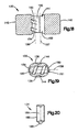
- Fig. 15 is an end view taken on line 15-15 of Fig. 13 ;
- Fig. 16 is an end view taken on line 16-16 of Fig. 13 ;
- Fig. 17 is an enlarged partial view of the part shown in Fig. 13 ;
- Fig. 18 is a sectional view taken on line 18-18 of Fig. 13 ;
- Fig. 19 is a sectional view taken on line 19-19 of Fig. 13 ;
- Fig. 20 is a side view of a part of the inserter of Fig. 1 .
- the apparatus 10 shown in the drawings is a spinal implant inserter with parts that are examples of the structural elements recited in the claims.
- the inserter 10 thus includes examples of how a person of ordinary skill in the art can make and use the invention, and is described here to provide enablement and best mode of the invention without imposing limitations that are not recited in the claims.
- the drawings thus are illustrative of the inserter and are for purposes of description. In this regard, while the apparatus is described and illustrated for purposes of inserting an implant into the spine, it may be used for other types of implants to be inserted in other locations and in animals/objects other than humans.
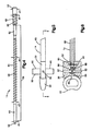
- the parts of the inserter 10 that are shown in Fig. 1 include a grip handle 12, a shaft 14, and a T-handle 16 on the end of the shaft 14.
- a pair of distracter springs 18, which may be referred to as paddles, may project forward from the grip handle 12.
- the shaft 14 extends through the grip handle 12, and may project forward from the grip handle 12 between the paddles 18.
- a pusher block 20 may be received between the paddles 18.
- the pusher block 20 is linked to or associated with the shaft 14 to be driven forward as the operator moves the T-handle 16 forward toward the grip handle 12.
- the pusher block 20 may then push a spinal implant 22 forward between the distal ends 24 of the paddles 18, which forces the paddles 18 apart from each other to simultaneously distract a pair of vertebrae and advance the implant 22 into the intravertebral space.
- the grip handle 12 may have a generally cylindrical configuration with a longitudinal central axis 25, and may be tapered radially inward toward its opposite ends.
- a counterbore 31 may extend axially inward from the proximal end 32 of the grip handle 12, which is on the right as viewed in the drawings.
- a similar counterbore 35 may extend axially inward from the distal end 36, which is on the left as viewed in the drawings.
- the counterbores 31, 35 and an inner bore 39 together may define a passage 41 extending longitudinally through the grip handle 12 along the axis 25.
- the handle 12 may be about 10cm to about 15cm in length.
- Another passage 43 may extend transversely through the grip handle 12. That passage 43 may cross the longitudinal passage 41, and may be centered on a transverse axis 45 perpendicular to the longitudinal axis 25. A pair of narrow, screw-threaded bores 47 may extend oppositely outward from the transverse passage 43, as best shown in Fig. 2 . Also extending transversely through the grip handle 12 may be a slot 49 which, as best shown in Fig. 1 , may be elongated lengthwise of the grip handle 12.
- the shaft 14 may have several distinct sections with differing lengths and diameters. As shown in Fig. 4 , these may include a proximal end section 50 with the largest diameter d1 on the shaft 14, and a distal end section 52 with the smallest diameter d2.
- the proximal end section 50 may be configured to receive the T-handle 16 ( Fig. 1 ).
- the distal end section 52 may be configured to receive the pusher block 20 ( Fig. 1 ).
- the shaft 14 may be about 30cm to about 40cm in length.
- the inserter 10 may be about 35cm to about 45cm in length.
- Other sections of the shaft 14 may include a major length section 56 which, in turn, may include a middle section 58 between two intermediate sections 60 and 62.
- the middle section 58 may be the longest individual section of the shaft 14, and may have a first screw thread 64 extending along nearly its entire length.
- the middle section 58 may have a third diameter d3 beside the screw thread 64, and may have a fourth diameter d4 at the screw thread 64.
- the intermediate sections 60 and 62 also may have the fourth diameter d4.
- Another intermediate section 66 with a larger diameter d5 may extend axially between the proximal end section 50 and the adjacent unthreaded intermediate section 62. That section 66 of the shaft 14 may have a second screw thread 68 with the largest diameter d1.
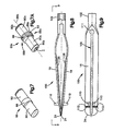
- the pusher block 20 may be mounted on the distal end section 52 of the shaft 14, and may be retained on the shaft 14 by a retainer ring 80.
- a forward surface 82 of the pusher block 20 may have a contour matching the contour of an opposed surface 84 of the spinal implant 22.
- an ejector rod 86 that may mounted on the pusher block 20.
- the ejector rod 86 may have a central portion 88 with a circular cross-section, and may have a pair of arms 90, which may have oval, elliptical, or any other suitable cross-sections.
- the ejector rod 86 may have at least one arm 90.
- the central portion 88 of the ejector rod 86 may be received in a circular bore 91 extending through the pusher block 20, as shown in Fig. 6 .
- the arms 90 may project from the pusher block 20, as shown in Fig. 5 .
- a pair of fasteners 92 may secure the ejector rod 86 on the pusher block 20.
- the inserter 10 has two paddles 18.
- the paddles 18 may be, as illustrated, separately flexible portions of a unitary spring structure 100, or in another embodiment, may be an assembly of multiple (e.g., two) springs affixed to a base.
- the spring structure 100 may have a tubular base 102 at its proximal end.
- the paddles 18 may be alike, and may be configured as elongated leaf springs that bow transversely outward from the base 102 and converge at their distal ends 24.
- At least one paddle 18 may have a centrally located slot 109 with a key-hole shaped opening 111 near the base 102.
- the opening 111 may provide a means by which the ejector rod 86 may be separated from the pusher block 20 so that a replacement ejector rod or ejector rod having a different configuration may be used with the inserter 10. For example, when the ejector rod 86 is positioned proximate or within the opening 111, the fasteners 92 may be disengaged from the ejector rod 86 and the ejector rod 86 may be removed from the pusher block 20 and removed from the opening 111.
- an alternative ejector rod 86a may be used with the inserter 10.
- the ejector rod 86a may have arms 90a and a central portion 88a having a longitudinal axis 86b. It should be noted that the ejector rod 86a may have at least one arm 90a. The arms 90a may be off-center with respect to the longitudinal axis 86b of the central portion 88a. Moreover, the ejector rod 86a may have one or more indentations 89 and a groove 93. The ejector rod 86a may be held in the pusher block 20 by fasteners 92 such as, for example, ball detents (not shown) which may engage the indentations 89.
- the central portion 88a may be rotated within the opening 111.
- a surgeon may rotate the ejector rod 86a such that the fasteners 92 may be disengaged from the indentations 89 and move along the groove 93.
- the fasteners 92 may then be engaged with another indentation 89 so that the arms 90a are closer or farther away from the distal ends 24 of the paddles 18.
- Such a construction may enable a surgeon to control the countersink depth of the implant 22 between the vertebrae.
- the countersink depth of the implant 22 may be about 3 mm, and in a position where a second side 88c of the central portion 88a faces the distal ends 24, the countersink depth of the implant 22 may be about 6 mm.
- the arms 90a may have surfaces 90b with indicia I which provide a visual indication of the countersink depth of the implant 22 when the ejector rod 86a is in different orientation.
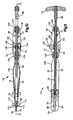
- a pair of stop structures 110 may project from opposite sides of the slot 109 near the distal end 24 of the paddle 18.
- the stop structures 110 prevent the inserter 10 from advancing too far into the intravertebral space.
- the stop feature may be adjustable to preselect the desired insertion distance. For example, there may be two insertion distance options effected by a stud or nub which may be hingedly attached to the stop structures 110 for positioning either distal to, or proximal to, the stop structures 110, at the election of the instrument user.
- Each paddle 18 further may have a pair of parallel, narrow ridges 112 that are closely spaced apart from each other at locations forward of the stop structures 110.
- the narrow ridges 112 may act as a retention feature to prevent the inserter 10 from dislodging itself while in operation.
- Each pair of ridges 112 may be interrupted by the adjacent slot 109, but may otherwise extend fully across the respective paddle 18.
- the paddles 18 may be about 17cm to about 27cm in length.
- the base 102 of the spring structure 100 may be received in the distal counterbore 35 in the grip handle 12.
- a fastener 114 may secure the base 142 in the counterbore 35.
- a fastener 116 may secure a sleeve 120 in the proximal counterbore 31.
- An internal screw thread 122 ( Fig. 12 ) on the sleeve 120 may be located in the passage 41 that extends through the grip handle 12 along the axis 25.
- the shaft 14 may extend and may be movable axially through the passage 41, with the first screw thread 64 on the shaft 14 spaced radially inward from the internal screw thread 122 in the passage 41.
- the arms 90 on the ejector rod 86 may project outward through the slots 109 on the paddles 18 to slide along the slots 109 as the pusher block 20 moves axially with the shaft 14.
- Axial movement of the shaft 14 and the pusher block 20 can be accomplished in either of two different modes of operation.
- the shaft 14 can slide freely through the passage 41 until the second screw thread 68 (adjacent to the T-handle 16) on the shaft 14 moves forward into engagement with the internal screw thread 122 in the sleeve 120 on the grip handle 12. Further advancement of the pusher block 20 and the implant 22 may be accomplished by rotating the T-handle 16 relative to the grip handle 12 so as to screw the shaft 14 forward along the axis 25.
- the shaft 14 does not slide freely through the passage 41 in the grip handle 12, but can be moved axially forward only by rotating the T-handle 16 to screw the shaft 14 through the passage 41. The operator can shift the inserter 10 between the two different modes of operation by shifting a clutch mechanism 130 that is mounted on the grip handle 12.
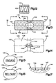
- the clutch mechanism 130 may include a moveable clutch member 132 and a pair of fasteners (e.g., ball detents 134) operably connected to the handle 12.
- the clutch member 132 may be a cylindrical part with flattened upper and lower side surfaces 136 and 138. End surfaces 140 and 142 of the clutch member 132 can have actuation indicia, as shown in Figs. 15 and 16 .
- a pair of recessed surfaces 144 may be located ( e.g ., centrally) on at least one opposite side surface 136 and 138.
- the recessed surfaces 144 may be alike, and each may have a cam surface portion 146 ( Fig. 19 ) defining a pair of pockets 147 and 149.
- the pockets 147 and 149 in the illustrated example may have tear-drop shapes extending oppositely away from each other lengthwise of the clutch member 132.
- An inner surface 150 of the clutch member 132 may define a passage 151.
- the inner surface 150 may have distinct portions 152 and 154 on opposite sides of the passage 151.
- the first side portion 152 of the inner surface 150 may have a semi-cylindrical contour centered on a first axis 157.
- the second side portion 154 may have a semi-cylindrical contour centered on a second axis 159 that is spaced from the first axis 157, and may define a screw thread 160 extending partly around the second axis 159.
- the clutch member 132 may extend through the transverse passage 43 in the grip handle 12.
- the passage 151 that extends through the clutch member 132 may be aligned with the longitudinal passage 41 in the grip handle 12.
- the ball detents 134 may engage and may retain the clutch member 132 on the grip handle 12.
- each ball detent 134 may have a casing 164 with an external screw thread 166, as shown in Fig. 20 .
- the ball detents 134 may be screwed into the narrow bores 47 ( Fig. 2 ) in the grip handle 12 to positions in which the balls 168 at the ends of the casings 164 project into the passage 43.
- the balls 168 may both be seated in either the first or second pockets 147 or 149 in the clutch member 132.
- the operator can force the cam surfaces 146 to slide against the resistance of the ball detents 134 so as to shift the clutch member 132 back and forth between a first position in which the balls 168 are seated in the first pockets 147 and a second position in which the balls 168 are seated in the second pockets 149.
- the unthreaded inner surface 152 may be located beside the first screw thread 64 on the shaft 14, as shown in Fig. 11 .
- the internal screw thread 160 at the opposite side of the passage 151 may then be spaced transversely from the first screw 64 thread on the shaft 14. Accordingly, the thread 160 does not mate with the thread 64, and the shaft 14 is free to slide along the axis 25.
- the clutch member 132 When the clutch member 132 is shifted from the first position to the second position, the unthreaded inner surface 152 of the clutch member 132 is moved transversely away from the first screw thread 64 on the shaft 14.
- the internal screw thread 160 on the clutch member 132 may simultaneously be moved transversely into engagement with the first screw thread 64 on the shaft 14. Accordingly, when the clutch member 132 is in the second position, the operator can move the shaft 14 along the axis 25 only by rotating the T-handle 16 relative to the grip handle 12 so as to screw the shaft 14 through the passage 41 in the grip handle 12.
- the internal screw threads 160 and 122 may be respectively positioned, and have the same pitch, such that as the shaft 14 moves along the axis 25, the screw thread 64 on the shaft 14 mates simultaneously with the internal screw threads 160 and 122.
- each of the paddles 18 may have a plurality (e.g., two) rails 26 to engage corresponding groove(s) on the outer (e.g., upper and lower) surfaces of the implant 22.
- the operator may move the shaft 14 and the pusher block 20 axially forward until the forward surface 82 of the pusher block 20 engages the complementary surface 84 of the implant 22.
- the distal ends 24 of the paddles 18 inserted between a pair of vertebrae, and with the stop structures 110 abutting the vertebrae, further forward movement of the pusher block 20 forces the implant 22 between the distal ends 24 of the paddles 18. This moves the paddles 18 apart from each other to distract the vertebrae according to the thickness of the implant 22, and simultaneously moves the implant 22 into the intravertebral space.
- the clutch member 132 is in the first position, the rod 14 and pusher block 20 may be advanced through this first range of movement merely by sliding the rod 14 forward along the axis 25 without the need to rotate the T-handle 16.
- the rod 14 and the pusher block 20 can be advanced through the first range of movement only by rotating the T-handle 16 to screw the rod 14 through the grip handle 12, as described above.
- a second range of movement follows as the second screw thread 68 on the shaft 14 moves axially into engagement with the internal screw thread 122 in the sleeve 120.
- the pusher block 20 drives the implant 22 out from between the distal ends 24 of the paddles 18.
- the arms 90, 90a of the ejector rod 86, 86a may engage the outer walls of the adjacent vertebrae. Rotation of the shaft 14 may result in the arms 90, 90a pushing against the vertebrae, thereby causing the paddles 18 to be withdrawn from in between the vertebrae in the second range of movement.
- the various ranges of threaded movement, effected by the various threaded regions have the same respective pitches effecting the same rate or pace of movement along the respective regions.
Landscapes
- Health & Medical Sciences (AREA)
- Orthopedic Medicine & Surgery (AREA)
- Biomedical Technology (AREA)
- Transplantation (AREA)
- Engineering & Computer Science (AREA)
- Life Sciences & Earth Sciences (AREA)
- Animal Behavior & Ethology (AREA)
- Heart & Thoracic Surgery (AREA)
- General Health & Medical Sciences (AREA)
- Public Health (AREA)
- Veterinary Medicine (AREA)
- Oral & Maxillofacial Surgery (AREA)
- Vascular Medicine (AREA)
- Cardiology (AREA)
- Physical Education & Sports Medicine (AREA)
- Surgery (AREA)
- Neurology (AREA)
- Nuclear Medicine, Radiotherapy & Molecular Imaging (AREA)
- Molecular Biology (AREA)
- Medical Informatics (AREA)
- Prostheses (AREA)
- Surgical Instruments (AREA)
Description
- This technology relates to devices that are used to install implants, for example, in the human spine.
- A spinal implant inserter is a device that installs an implant between two (e.g., a pair of adjacent) vertebrae, or wholly or partially within a vertebra, in the human spine. Such a device is typically operated manually, and may include a rod that the operator uses to push the spinal implant into the intravertebral space. The inserter may be used, for example, for an anterior approach, a posterior approach, a lateral approach, or any variation in between.
-
US 3,486,505 discloses an instrument to distract two adjacent vertebrae and at the same time inverting a spinal implant between the vertebrae. The instrument comprises a handle and a shaft, wherein the shaft is movable within a passage of the shaft and is operably connected to a pusher block, the pusher block contacting the spinal implant to push forward the implant between the two adjacent vertebrae as the shaft is advanced. - An apparatus for use with a spinal implant which comprises a handle structure with a longitudinal axis and a passage, a shaft which is be movable within the passage and has at least a portion having a first screw thread, a pusher block which is operably connected to the shaft and has a forward surface configured to engage the spinal implant, and a clutch member which is supported on the handle structure for movement into and out of engagement with the first screw thread of the shaft. The apparatus may also include a pair of paddles which may have a distal end, a proximal end and may project from the handle. The inserter may be used, for example, for an anterior approach, a posterior approach, a lateral approach, or any variation in between.
- The handle structure may have an internal thread, and the shaft may have a second screw thread movable along the longitudinal axis into engagement with the internal thread on the handle structure when the clutch member is either engaged or disengaged with the first screw thread of the shaft. In some embodiments, the handle may have an internal thread and the shaft may have at least a portion which may have a first screw thread spaced from the internal thread such that the shaft can slide axially through a first range of movement in the passage. At least a different portion of the shaft may have a second screw thread. The second screw thread may be moveable into engagement with the internal thread such that the shaft can only be rotated through a second range of movement in the passage. The shaft may be configured for the second range of movement to follow the first range of movement when the shaft is moved forward through the passage.
- The pusher block is moveable with and linked to the shaft. The pusher block may have a receiving portion sized and configured to receive an ejector rod. The ejector rod may comprise a central portion having a longitudinal axis and two arms extending from the central portion. In one embodiment, the arms may be offset from the longitudinal axis of the central portion. The central portion of the ejector rod may comprise a plurality of indentations and a groove. The pusher block may have at least one fastener for engaging the indentations and groove such that the ejector rod may be rotatable relative to the pusher block. In some embodiments, the ejector rod may have at least one arm and may be operably connected to and/or disengageable from the pusher block. In an embodiment where at least one paddle has a slot, the at least one arm may be moveable in the slot between the distal and proximal ends of the paddle. The ejector rod may be releasably connected to the pusher block. At least one of the paddles may comprise an opening such that when the ejector rod is positioned in the opening, the ejector rod may be disengageable from and/or rotatable relative to the pusher block.
- At least a portion of the shaft may be located between the paddles and may move through the proximal end of the paddles. The distal ends of the paddles are sized and configured to be positioned between adjacent vertebrae. Moreover, the paddles may be configured so that the distal ends of the paddles are biased together. The proximal ends of the paddles are sized and configured to be operably attached to the handle. In one embodiment, at least one paddle may have at least one ridge at the distal end thereof, the ridge may enhance engagement of the at least one paddle with a vertebra. In some embodiments, at least one paddle may have at least one stop structure for engaging at least one vertebra, the at least one stop structure may be configured to prevent over penetration of the distal end of the paddles into adjacent vertebrae. At least one of the pair of paddles may have a slot such that the ejector rod may move along the slot. The paddles may be configured so that the distal ends of the paddles may move away from each other as the pusher block moves from the proximal end of the paddles to the distal end of the paddles.
- The clutch member may comprise an opening therethrough having a first portion and a second portion, wherein the first portion may comprise a threaded portion and the second portion may comprise an unthreaded portion. The clutch member may also comprise a first side portion and at least a pair of pockets on the side portion, The handle may have a first fastener which may selectively engage only one of the pair of pockets at a time. The clutch member may further comprise a second side portion and a second pair of packets on the second side portion. The handle may have a second fastener which may selectively engage only one of the second pair of pockets at a time. In one embodiment, the first and second fasteners may be ball detents positioned through the handle. The clutch member may be supported on the handle for movement into and out of engagement with the first screw thread on the shaft such that the shaft may only rotate through a first range of movement in the passage when the clutch member is engaged with the first screw thread. The clutch member may be supported on the handle structure for movement between a first position, wherein the shaft is capable of sliding within the handle parallel to the longitudinal axis, and a second position, wherein the shaft is capable of moving within the handle in a second manner different than longitudinal movement. The second different manner of movement may include at least in part by rotating the shaft.
- A method (not forming part of the invention) of inserting an implant between adjacent vertebrae may comprise providing an implant inserter comprising a handle structure which may have a longitudinal axis and a passage, a pair of paddles which may extend from the handle and may have a distal end and a proximal end, a shaft which may be moveable within the passage and at least a portion which may have a first threaded portion, a pusher block which may be operably connected to the shaft and may have a forward surface which may be configured to engage the spinal implant, and a clutch member, at least a portion of which may have screw threads for selectively engaging the first threaded portion of the shaft. The method may further comprise inserting an implant against the pusher block and in between the paddles, inserting the distal ends of the paddles in between adjacent vertebrae, moving the shaft through the passage of the handle such that the implant may move towards the distal end of the paddles and may spread the paddles apart, and withdrawing the paddles from in between adjacent vertebrae. Additionally, the method may include moving the screw threads of the clutch member into engagement with the first threaded portion of the shaft. Moreover, in an embodiment wherein the shaft may comprise a second threaded portion and the handle may comprise an internal thread, the method may further comprise engaging the second threaded portion of the shaft with the internal thread of the handle and rotating the shaft relative to the handle to move the pusher block between the paddles. The paddles may be moved apart as the implant moves towards the distal ends of the paddles. In embodiments where the implant inserter may comprise an ejector rod operably connected to the pusher block, the ejector rod may be engaged with at least one vertebra such that as the shaft rotates the distal ends of the paddles may move out from in between adjacent vertebrae. Furthermore, in an embodiment where the implant inserter may comprise an ejector rod operably connected to the pusher block and at least one of the paddles may comprise an opening, the method may further comprise rotating the ejector rod within the opening.
- The invention and further developments of the invention are explained in even greater detail in the following exemplary drawings. The present invention can be better understood by reference to the following drawings, wherein like references numerals represent like elements. The drawings are merely exemplary to illustrate certain features that may be used singularly or in combination with other features and the present invention should not be limited to the embodiments shown.
-
Fig. 1 is a perspective view of a spinal implant inserter with a spinal implant; -
Fig. 2 is a sectional view of a part of the inserter shown inFig. 1 ; -
Fig. 3 is a sectional view taken on line 3-3 ofFig. 2 ; -
Fig. 4 is a side view of a part of the inserter ofFig. 1 ; -
Fig. 5 is an enlarged view of the implant and parts of the inserter ofFig. 1 ; -
Fig. 6 is a sectional view taken on line 6-6 ofFig. 5 ; -
Fig. 7 is a perspective view of a part shown inFigs. 5 and 6 ; -
Fig. 7A is a perspective view of an alternative embodiment of the part ofFig. 7 ; -
Fig. 8 is a side view of a part of the inserter ofFig. 1 ; -
Fig. 9 is a top view of the part shown inFig. 8 ; -
Fig. 10 is a side view of the implant and inserter ofFig. 1 , with certain parts shown in section; -
Fig. 11 is a view taken on line 11-11 ofFig. 10 ; -
Fig. 12 is a sectional view of a part of the inserter ofFig. 1 ; -
Fig. 13 is a side view, taken in section, of a part of the inserter ofFig. 1 ; -
Fig. 14 is a top view of the part shown inFig. 13 ; -
Fig. 15 is an end view taken on line 15-15 ofFig. 13 ; -
Fig. 16 is an end view taken on line 16-16 ofFig. 13 ; -
Fig. 17 is an enlarged partial view of the part shown inFig. 13 ; -
Fig. 18 is a sectional view taken on line 18-18 ofFig. 13 ; -
Fig. 19 is a sectional view taken on line 19-19 ofFig. 13 ; and -
Fig. 20 is a side view of a part of the inserter ofFig. 1 . - The
apparatus 10 shown in the drawings is a spinal implant inserter with parts that are examples of the structural elements recited in the claims. Theinserter 10 thus includes examples of how a person of ordinary skill in the art can make and use the invention, and is described here to provide enablement and best mode of the invention without imposing limitations that are not recited in the claims. The drawings thus are illustrative of the inserter and are for purposes of description. In this regard, while the apparatus is described and illustrated for purposes of inserting an implant into the spine, it may be used for other types of implants to be inserted in other locations and in animals/objects other than humans. - The parts of the
inserter 10 that are shown inFig. 1 include agrip handle 12, ashaft 14, and a T-handle 16 on the end of theshaft 14. A pair of distracter springs 18, which may be referred to as paddles, may project forward from thegrip handle 12. Theshaft 14 extends through thegrip handle 12, and may project forward from the grip handle 12 between thepaddles 18. - A
pusher block 20 may be received between thepaddles 18. Thepusher block 20 is linked to or associated with theshaft 14 to be driven forward as the operator moves the T-handle 16 forward toward thegrip handle 12. Thepusher block 20 may then push aspinal implant 22 forward between the distal ends 24 of thepaddles 18, which forces thepaddles 18 apart from each other to simultaneously distract a pair of vertebrae and advance theimplant 22 into the intravertebral space. - As shown separately in
Figs. 2 and 3 , the grip handle 12 may have a generally cylindrical configuration with a longitudinalcentral axis 25, and may be tapered radially inward toward its opposite ends. Acounterbore 31 may extend axially inward from theproximal end 32 of thegrip handle 12, which is on the right as viewed in the drawings. Asimilar counterbore 35 may extend axially inward from thedistal end 36, which is on the left as viewed in the drawings. Thecounterbores inner bore 39 together may define apassage 41 extending longitudinally through the grip handle 12 along theaxis 25. In a one embodiment, thehandle 12 may be about 10cm to about 15cm in length. - Another
passage 43 may extend transversely through thegrip handle 12. Thatpassage 43 may cross thelongitudinal passage 41, and may be centered on atransverse axis 45 perpendicular to thelongitudinal axis 25. A pair of narrow, screw-threadedbores 47 may extend oppositely outward from thetransverse passage 43, as best shown inFig. 2 . Also extending transversely through the grip handle 12 may be aslot 49 which, as best shown inFig. 1 , may be elongated lengthwise of thegrip handle 12. - The
shaft 14 may have several distinct sections with differing lengths and diameters. As shown inFig. 4 , these may include aproximal end section 50 with the largest diameter d1 on theshaft 14, and adistal end section 52 with the smallest diameter d2. Theproximal end section 50 may be configured to receive the T-handle 16 (Fig. 1 ). Thedistal end section 52 may be configured to receive the pusher block 20 (Fig. 1 ). In a one embodiment, theshaft 14 may be about 30cm to about 40cm in length. In one embodiment, theinserter 10 may be about 35cm to about 45cm in length. - Other sections of the
shaft 14 may include amajor length section 56 which, in turn, may include amiddle section 58 between twointermediate sections middle section 58 may be the longest individual section of theshaft 14, and may have afirst screw thread 64 extending along nearly its entire length. Themiddle section 58 may have a third diameter d3 beside thescrew thread 64, and may have a fourth diameter d4 at thescrew thread 64. Theintermediate sections intermediate section 66 with a larger diameter d5 may extend axially between theproximal end section 50 and the adjacent unthreadedintermediate section 62. Thatsection 66 of theshaft 14 may have asecond screw thread 68 with the largest diameter d1. - As shown in enlarged detail in
Figs. 5 and 6 , thepusher block 20 may be mounted on thedistal end section 52 of theshaft 14, and may be retained on theshaft 14 by aretainer ring 80. Aforward surface 82 of thepusher block 20 may have a contour matching the contour of anopposed surface 84 of thespinal implant 22. Also shown inFigs. 5 and 6 is anejector rod 86 that may mounted on thepusher block 20. As shown separately inFig. 7 , theejector rod 86 may have acentral portion 88 with a circular cross-section, and may have a pair ofarms 90, which may have oval, elliptical, or any other suitable cross-sections. It should be noted that theejector rod 86 may have at least onearm 90. Thecentral portion 88 of theejector rod 86 may be received in acircular bore 91 extending through thepusher block 20, as shown inFig. 6 . Thearms 90 may project from thepusher block 20, as shown inFig. 5 . A pair offasteners 92 may secure theejector rod 86 on thepusher block 20. - There may be one
paddle 18 or a plurality ofpaddles 18. In the illustrated embodiment, theinserter 10 has twopaddles 18. Thepaddles 18 may be, as illustrated, separately flexible portions of aunitary spring structure 100, or in another embodiment, may be an assembly of multiple (e.g., two) springs affixed to a base. As shown inFigs. 8 and 9 , thespring structure 100 may have atubular base 102 at its proximal end. Thepaddles 18 may be alike, and may be configured as elongated leaf springs that bow transversely outward from thebase 102 and converge at their distal ends 24. At least onepaddle 18 may have a centrally locatedslot 109 with a key-hole shapedopening 111 near thebase 102. Theopening 111 may provide a means by which theejector rod 86 may be separated from thepusher block 20 so that a replacement ejector rod or ejector rod having a different configuration may be used with theinserter 10. For example, when theejector rod 86 is positioned proximate or within theopening 111, thefasteners 92 may be disengaged from theejector rod 86 and theejector rod 86 may be removed from thepusher block 20 and removed from theopening 111. - As shown in
Fig. 7A , analternative ejector rod 86a may be used with theinserter 10. Theejector rod 86a may havearms 90a and acentral portion 88a having alongitudinal axis 86b. It should be noted that theejector rod 86a may have at least onearm 90a. Thearms 90a may be off-center with respect to thelongitudinal axis 86b of thecentral portion 88a. Moreover, theejector rod 86a may have one ormore indentations 89 and agroove 93. Theejector rod 86a may be held in thepusher block 20 byfasteners 92 such as, for example, ball detents (not shown) which may engage theindentations 89. When thearms 90a are located within theopening 111 of thepaddles 18, thecentral portion 88a may be rotated within theopening 111. A surgeon may rotate theejector rod 86a such that thefasteners 92 may be disengaged from theindentations 89 and move along thegroove 93. Thefasteners 92 may then be engaged with anotherindentation 89 so that thearms 90a are closer or farther away from the distal ends 24 of thepaddles 18. Such a construction may enable a surgeon to control the countersink depth of theimplant 22 between the vertebrae. For example, in a position where afirst side 88b of thecentral portion 88a faces the distal ends 24, the countersink depth of theimplant 22 may be about 3 mm, and in a position where asecond side 88c of thecentral portion 88a faces the distal ends 24, the countersink depth of theimplant 22 may be about 6 mm. Thearms 90a may havesurfaces 90b with indicia I which provide a visual indication of the countersink depth of theimplant 22 when theejector rod 86a is in different orientation. - A pair of
stop structures 110 may project from opposite sides of theslot 109 near thedistal end 24 of thepaddle 18. Thestop structures 110 prevent theinserter 10 from advancing too far into the intravertebral space. As further option, the stop feature may be adjustable to preselect the desired insertion distance. For example, there may be two insertion distance options effected by a stud or nub which may be hingedly attached to thestop structures 110 for positioning either distal to, or proximal to, thestop structures 110, at the election of the instrument user. - Each
paddle 18 further may have a pair of parallel,narrow ridges 112 that are closely spaced apart from each other at locations forward of thestop structures 110. Thenarrow ridges 112 may act as a retention feature to prevent theinserter 10 from dislodging itself while in operation. Each pair ofridges 112 may be interrupted by theadjacent slot 109, but may otherwise extend fully across therespective paddle 18. In a one embodiment, thepaddles 18 may be about 17cm to about 27cm in length. - As shown in
Figs. 10 and 11 , thebase 102 of thespring structure 100 may be received in thedistal counterbore 35 in thegrip handle 12. Afastener 114 may secure the base 142 in thecounterbore 35. At the other end of thegrip handle 12, afastener 116 may secure asleeve 120 in theproximal counterbore 31. An internal screw thread 122 (Fig. 12 ) on thesleeve 120 may be located in thepassage 41 that extends through the grip handle 12 along theaxis 25. Theshaft 14 may extend and may be movable axially through thepassage 41, with thefirst screw thread 64 on theshaft 14 spaced radially inward from theinternal screw thread 122 in thepassage 41. Thearms 90 on theejector rod 86 may project outward through theslots 109 on thepaddles 18 to slide along theslots 109 as thepusher block 20 moves axially with theshaft 14. - Axial movement of the
shaft 14 and thepusher block 20 can be accomplished in either of two different modes of operation. In the first mode, theshaft 14 can slide freely through thepassage 41 until the second screw thread 68 (adjacent to the T-handle 16) on theshaft 14 moves forward into engagement with theinternal screw thread 122 in thesleeve 120 on thegrip handle 12. Further advancement of thepusher block 20 and theimplant 22 may be accomplished by rotating the T-handle 16 relative to the grip handle 12 so as to screw theshaft 14 forward along theaxis 25. In the second mode of operation, theshaft 14 does not slide freely through thepassage 41 in thegrip handle 12, but can be moved axially forward only by rotating the T-handle 16 to screw theshaft 14 through thepassage 41. The operator can shift theinserter 10 between the two different modes of operation by shifting aclutch mechanism 130 that is mounted on thegrip handle 12. - The
clutch mechanism 130 may include a moveableclutch member 132 and a pair of fasteners (e.g., ball detents 134) operably connected to thehandle 12. As shown inFigs. 13-19 , theclutch member 132 may be a cylindrical part with flattened upper and lower side surfaces 136 and 138. End surfaces 140 and 142 of theclutch member 132 can have actuation indicia, as shown inFigs. 15 and 16 . A pair of recessedsurfaces 144 may be located (e.g., centrally) on at least oneopposite side surface Fig. 19 ) defining a pair ofpockets Fig. 14 , thepockets clutch member 132. - An
inner surface 150 of theclutch member 132 may define apassage 151. Theinner surface 150 may havedistinct portions passage 151. Thefirst side portion 152 of theinner surface 150 may have a semi-cylindrical contour centered on afirst axis 157. Thesecond side portion 154 may have a semi-cylindrical contour centered on asecond axis 159 that is spaced from thefirst axis 157, and may define ascrew thread 160 extending partly around thesecond axis 159. - Referring again to
Figs. 10 and 11 , theclutch member 132 may extend through thetransverse passage 43 in thegrip handle 12. Thepassage 151 that extends through theclutch member 132 may be aligned with thelongitudinal passage 41 in thegrip handle 12. The ball detents 134 may engage and may retain theclutch member 132 on thegrip handle 12. Specifically, eachball detent 134 may have acasing 164 with anexternal screw thread 166, as shown inFig. 20 . The ball detents 134 may be screwed into the narrow bores 47 (Fig. 2 ) in the grip handle 12 to positions in which theballs 168 at the ends of thecasings 164 project into thepassage 43. When theclutch member 132 is installed in thepassage 43, theballs 168 may both be seated in either the first orsecond pockets clutch member 132. By pushing alternately against the twoend surfaces ball detents 134 so as to shift theclutch member 132 back and forth between a first position in which theballs 168 are seated in thefirst pockets 147 and a second position in which theballs 168 are seated in the second pockets 149. - When the
clutch member 132 is in the first position, the unthreadedinner surface 152 may be located beside thefirst screw thread 64 on theshaft 14, as shown inFig. 11 . Theinternal screw thread 160 at the opposite side of thepassage 151 may then be spaced transversely from thefirst screw 64 thread on theshaft 14. Accordingly, thethread 160 does not mate with thethread 64, and theshaft 14 is free to slide along theaxis 25. - When the
clutch member 132 is shifted from the first position to the second position, the unthreadedinner surface 152 of theclutch member 132 is moved transversely away from thefirst screw thread 64 on theshaft 14. Theinternal screw thread 160 on theclutch member 132 may simultaneously be moved transversely into engagement with thefirst screw thread 64 on theshaft 14. Accordingly, when theclutch member 132 is in the second position, the operator can move theshaft 14 along theaxis 25 only by rotating the T-handle 16 relative to the grip handle 12 so as to screw theshaft 14 through thepassage 41 in thegrip handle 12. Theinternal screw threads shaft 14 moves along theaxis 25, thescrew thread 64 on theshaft 14 mates simultaneously with theinternal screw threads - In use of the
inserter 10, the operator may manually slide theimplant 22 forward between thepaddles 18 to spread them apart until their spring force holds theimplant 22 in place. A rail-groove type relationship may be established betweenpaddles 18 and theimplant 22 to keep theimplant 22 in proper alignment with thepaddles 18 as theimplant 22 is advanced distally. For example, each of thepaddles 18 may have a plurality (e.g., two) rails 26 to engage corresponding groove(s) on the outer (e.g., upper and lower) surfaces of theimplant 22. - The operator may move the
shaft 14 and thepusher block 20 axially forward until theforward surface 82 of thepusher block 20 engages thecomplementary surface 84 of theimplant 22. With the distal ends 24 of thepaddles 18 inserted between a pair of vertebrae, and with thestop structures 110 abutting the vertebrae, further forward movement of thepusher block 20 forces theimplant 22 between the distal ends 24 of thepaddles 18. This moves thepaddles 18 apart from each other to distract the vertebrae according to the thickness of theimplant 22, and simultaneously moves theimplant 22 into the intravertebral space. If theclutch member 132 is in the first position, therod 14 and pusher block 20 may be advanced through this first range of movement merely by sliding therod 14 forward along theaxis 25 without the need to rotate the T-handle 16. - However, if the
clutch member 132 is in the second position, therod 14 and thepusher block 20 can be advanced through the first range of movement only by rotating the T-handle 16 to screw therod 14 through thegrip handle 12, as described above. In either case, a second range of movement follows as thesecond screw thread 68 on theshaft 14 moves axially into engagement with theinternal screw thread 122 in thesleeve 120. As theshaft 14 is screwed forward through the second range of movement, thepusher block 20 drives theimplant 22 out from between the distal ends 24 of thepaddles 18. As theimplant 22 moves beyond the distal ends 24 of thepaddles 18 and in between adjacent vertebrae, thearms ejector rod shaft 14 may result in thearms paddles 18 to be withdrawn from in between the vertebrae in the second range of movement. In the illustrated embodiments, the various ranges of threaded movement, effected by the various threaded regions, have the same respective pitches effecting the same rate or pace of movement along the respective regions. - While the foregoing description and drawings represent the preferred embodiments of the present invention, it will be understood that various additions, modifications and substitutions may be made therein without departing from the scope of the present invention as defined in the accompanying claims, In particular, it will be clear to those skilled in the art that the present invention may be embodied in other specific forms, structures, arrangements, proportions, and with other elements, materials, and components, without departing from essential characteristics thereof. One skilled in the art will appreciate that the invention may be used with many modifications of structure, arrangement, proportions, materials, and components and otherwise, used in the practice of the invention, which are particularly adapted to specific environments and operative requirements without departing from the principles of the present invention. The presently disclosed embodiments are therefore to be considered in all respects as illustrative and not restrictive, the scope of the invention being indicated by the appended claims, and not limited to the foregoing description.
Claims (27)
- An apparatus (10) for use with a spinal implant (22), comprising:a handle structure (12) having a longitudinal axis (25) and a passage (41);a shaft (14) moveable within the passage (41), at least a portion (58) of the shaft (14) having a first screw thread (64); anda pusher block (20) operably connected to the shaft (14) and having a forward surface (82) configured to contact the spinal implant (22), characterized in thata clutch member (132) supported on the handle structure (12) for movement into and out of engagement with the first screw thread (64) of the shaft (14).
- The apparatus as defined in claim 1, wherein the handle structure (12) has an internal thread (122), the first screw thread (64) being spaced from the internal thread (122) such that the shaft (14) can axially slide through a first range of movement in the passage (41), the shaft (14) further including a second screw thread (68) spaced from the first screw thread (64), the second screw thread (68) defining a second range of movement, the second screw thread (68) being moveable into engagement with the internal thread (122) such that the shaft (14) can only be rotated through the second range of movement.
- The apparatus as defined in claim 2, wherein the shaft (14) is configured for the second range of movement to follow the first range of movement as the shaft (14) is moved through the passage (41).
- The apparatus as defined in claims 2 and 3, wherein at least a portion of the clutch member (132) includes screw threads (160) such that the shaft (14) can only rotate through the first range of movement in the passage (41) when the clutch member (132) is engaged with the first screw thread (64).
- The apparatus as defined in claim 1, wherein the handle structure (12) has an internal screw thread (122) and the shaft (14) has a second screw thread (68) moveable along the longitudinal axis (25) into engagement with the internal screw thread (122) on the handle structure (12) when the clutch member (132) is either engaged or disengaged with the first screw thread (64) of the shaft (14).
- The apparatus as defined in any of the above claims, further comprising a pair of paddles (18) projecting from an end (36) of the handle (12), at least a portion of the shaft being located between the paddles (18), the paddles (18) having a distal end (24) and a proximal end, wherein the distal ends (24) of the paddles (18) are sized and configured to be positioned between adjacent vertebrae and wherein the proximal ends of the paddles (18) are sized and configured to be operably attached to the handle (12).
- The apparatus as defined in claim 6, wherein the pusher block (20) has a receiving portion (91), the receiving portion (91) being sized and configured to receive an ejector rod (86, 86a), wherein the ejector rod (86, 86a) is engageable with at least one vertebra such that rotation of the shaft (14) causes the distal ends (24) of the paddles (18) to be withdrawn from in between adjacent vertebrae.
- The apparatus as defined in claim 7, wherein the ejector rod (86, 86a) comprises a central portion (88, 88a) having a longitudinal axis (86b) and two arms (90, 90a) extending from the central portion (88, 88a).
- The apparatus as defined in claim 8, wherein the arms (90a) are offset from the longitudinal axis (86b) of the central portion (88a).
- The apparatus as defined in claim 8, wherein the central portion (88a) of the ejector rod (86a) comprises a plurality of indentations (89) and a groove (93), the pusher block (20) comprising at least one fastener (92) for engaging the indentations (89) and groove (93) such that the ejector rod (86a) is rotatable relative to the pusher block (20).
- The apparatus as defined in claim 1, further comprising a pair of paddles (18) extending from the handle (12), the paddles (18) having a distal end (24) and a proximal end, wherein the distal ends (24) of the paddles (18) are sized and configured to be positioned between adjacent vertebrae and wherein the proximal ends of the paddles (18) are sized and configured to be operably attached to the handle (12).
- The apparatus as defined in claim 11, wherein at least one paddle (18) has at least one ridge (112) at the distal end (24) thereof.
- The apparatus as defined in any of the above claims, wherein the clutch member (132) comprises an opening (151) therethrough having a first portion (154) and a second portion (152).
- The apparatus as defined in claim 13, wherein the first portion (154) comprises a threaded portion (160) and the second portion (152) comprises an unthreaded portion.
- The apparatus as defined in claims 13 and 14, wherein the clutch member (132) further comprises a first side portion (146) and at least a pair of pockets (147, 149) on the side portion (146), the handle (12) having a first fastener (134) for selectively engaging only one of the pair of pockets (147, 149) at a time.
- The apparatus as defined in claim 15, wherein the clutch member (132) further comprises a second side portion (146) and a second pair of pockets (147, 149) on the second side portion (146), the handle (12) having a second fastener (134) for selectively engaging only one of the second pair of pockets (147, 149) at a time.
- The apparatus as defined in claim 16, wherein the first and second fasteners (134) are ball detents positioned through the handle (12).
- The apparatus as defined in claim 11, wherein at least one of the pair of paddles (18) has a slot (109).
- The apparatus as defined in claim 18, further comprising an ejector rod (86, 86a) having at least one arm (90, 90a), wherein the ejector rod (86, 86a) is operably connected to the pusher block (20), and engageable with at least one vertebra such that rotation of the shaft (14) causes the distal ends (24) of the paddles (18) to be withdrawn from in between adjacent vertebrae, the at least one arm (90, 90a) being moveable in the slot (109) between the distal (24) and proximal ends of at least one paddle (18).
- The apparatus as defined in claims 18 and 19, wherein the paddles (18) are configured so that the distal ends (24) of the paddles (18) move away from each other as the pusher block (20) moves from the proximal end of the paddles (18) to the distal end (24) of the paddles (18).
- The apparatus as defined in claims 19 and 20, wherein the ejector rod (86, 86a) is releasably connected to the pusher block (20).
- The apparatus as defined in any of claims 18 to 21, wherein at least one paddle (18) has at least one stop structure (110) for contacting at least one vertebra, and the at least one stop structure (110) is configured to prevent over penetration of the distal end (24) of the paddles (18) into the adjacent vertebrae.
- The apparatus as defined in claim 1, wherein the clutch member (132) is sized and configured to move between a first position, wherein the shaft (14) is capable of sliding within the handle (12) parallel to the longitudinal axis (25), and a second position, wherein the shaft (14) cannot slide within the handle (12) parallel to the longitudinal axis (25), but is capable of moving within the handle (12) in a second manner different than longitudinal movement.
- The apparatus as defined in claim 23, wherein the second manner of movement includes at least in part rotating the shaft (14).
- The apparatus as defined in claim 11, further comprising an ejector rod (86, 86a) wherein the ejector rod (86, 86a) is operably connected to and disengageable from the pusher block (20), and engageable with at least one vertebra such that rotation of the shaft (14) causes the distal ends (24) of the paddles (18) to be withdrawn from in between adjacent vertebrae and the paddles (18) are configured such that the distal ends (24) are biased together.
- The apparatus as defined in claim 25, wherein at least one of the paddles (18) comprises an opening (111) such that when the ejector rod (86, 86a) is positioned in the opening (111), the ejector rod (86, 86a) is disengageable from the pusher block (20).
- The apparatus as defined in either of claim 25, wherein at least one of the paddles (18) comprises an opening (111) such that when the ejector rod (86, 86a) is positioned in the opening (111), the ejector rod (86, 86a) is rotatable with respect to the pusher block (20).
Priority Applications (1)
| Application Number | Priority Date | Filing Date | Title |
|---|---|---|---|
| EP13155958.5A EP2599463B1 (en) | 2005-02-25 | 2006-02-22 | Spinal implant insertion apparatus |
Applications Claiming Priority (2)
| Application Number | Priority Date | Filing Date | Title |
|---|---|---|---|
| US65670705P | 2005-02-25 | 2005-02-25 | |
| PCT/US2006/006191 WO2006093737A2 (en) | 2005-02-25 | 2006-02-22 | Implant insertion apparatus and method of use |
Related Child Applications (2)
| Application Number | Title | Priority Date | Filing Date |
|---|---|---|---|
| EP13155958.5A Division EP2599463B1 (en) | 2005-02-25 | 2006-02-22 | Spinal implant insertion apparatus |
| EP13155958.5 Division-Into | 2013-02-20 |
Publications (2)
| Publication Number | Publication Date |
|---|---|
| EP1855626A2 EP1855626A2 (en) | 2007-11-21 |
| EP1855626B1 true EP1855626B1 (en) | 2013-12-04 |
Family
ID=36572176
Family Applications (2)
| Application Number | Title | Priority Date | Filing Date |
|---|---|---|---|
| EP13155958.5A Active EP2599463B1 (en) | 2005-02-25 | 2006-02-22 | Spinal implant insertion apparatus |
| EP06735732.7A Active EP1855626B1 (en) | 2005-02-25 | 2006-02-22 | Implant insertion apparatus |
Family Applications Before (1)
| Application Number | Title | Priority Date | Filing Date |
|---|---|---|---|
| EP13155958.5A Active EP2599463B1 (en) | 2005-02-25 | 2006-02-22 | Spinal implant insertion apparatus |
Country Status (10)
| Country | Link |
|---|---|
| US (4) | US7722622B2 (en) |
| EP (2) | EP2599463B1 (en) |
| JP (1) | JP4799569B2 (en) |
| KR (1) | KR101255684B1 (en) |
| CN (1) | CN101163456B (en) |
| AU (1) | AU2006218910A1 (en) |
| CA (1) | CA2611932C (en) |
| ES (1) | ES2525134T3 (en) |
| TW (1) | TWI407944B (en) |
| WO (1) | WO2006093737A2 (en) |
Families Citing this family (113)
| Publication number | Priority date | Publication date | Assignee | Title |
|---|---|---|---|---|
| US8317798B2 (en) * | 2002-06-25 | 2012-11-27 | Warsaw Orthopedic | Minimally invasive expanding spacer and method |
| US11890181B2 (en) * | 2002-07-22 | 2024-02-06 | Tmt Systems, Inc. | Percutaneous endovascular apparatus for repair of aneurysms and arterial blockages |
| WO2004066865A2 (en) | 2003-01-31 | 2004-08-12 | Spinalmotion, Inc. | Spinal midline indicator |
| EP1587462B1 (en) | 2003-01-31 | 2012-06-06 | Malan De Villiers | Intervertebral prosthesis placement instrument |
| EP2161008B1 (en) | 2003-05-27 | 2014-12-24 | Simplify Medical, Inc. | Method for assembling a prosthetic disc for intervertebral insertion |
| US10052211B2 (en) | 2003-05-27 | 2018-08-21 | Simplify Medical Pty Ltd. | Prosthetic disc for intervertebral insertion |
| US7575599B2 (en) | 2004-07-30 | 2009-08-18 | Spinalmotion, Inc. | Intervertebral prosthetic disc with metallic core |
| US7153325B2 (en) * | 2003-08-01 | 2006-12-26 | Ultra-Kinetics, Inc. | Prosthetic intervertebral disc and methods for using the same |
| US7686826B2 (en) * | 2003-10-30 | 2010-03-30 | Cambridge Endoscopic Devices, Inc. | Surgical instrument |
| US7338513B2 (en) * | 2003-10-30 | 2008-03-04 | Cambridge Endoscopic Devices, Inc. | Surgical instrument |
| US7842028B2 (en) | 2005-04-14 | 2010-11-30 | Cambridge Endoscopic Devices, Inc. | Surgical instrument guide device |
| US7147650B2 (en) * | 2003-10-30 | 2006-12-12 | Woojin Lee | Surgical instrument |
| US7585326B2 (en) | 2004-08-06 | 2009-09-08 | Spinalmotion, Inc. | Methods and apparatus for intervertebral disc prosthesis insertion |
| US8083797B2 (en) | 2005-02-04 | 2011-12-27 | Spinalmotion, Inc. | Intervertebral prosthetic disc with shock absorption |
| US20060241641A1 (en) * | 2005-04-22 | 2006-10-26 | Sdgi Holdings, Inc. | Methods and instrumentation for distraction and insertion of implants in a spinal disc space |
| US20070088436A1 (en) * | 2005-09-29 | 2007-04-19 | Matthew Parsons | Methods and devices for stenting or tamping a fractured vertebral body |
| US8105331B2 (en) * | 2005-10-03 | 2012-01-31 | Globus Medical, Inc. | Spinal surgery distractor with an integrated retractor |
| US8377072B2 (en) | 2006-02-06 | 2013-02-19 | Depuy Spine, Inc. | Medical device installation tool |
| US7875034B2 (en) * | 2006-03-14 | 2011-01-25 | Warsaw Orthopedic, Inc. | Spinal disc space preparation instruments and methods for interbody spinal implants |
| US8066714B2 (en) * | 2006-03-17 | 2011-11-29 | Warsaw Orthopedic Inc. | Instrumentation for distraction and insertion of implants in a spinal disc space |
| JP2009533187A (en) | 2006-04-12 | 2009-09-17 | スパイナルモーション, インコーポレイテッド | Posterior spine apparatus and method |
| US8105350B2 (en) * | 2006-05-23 | 2012-01-31 | Cambridge Endoscopic Devices, Inc. | Surgical instrument |
| US7615067B2 (en) * | 2006-06-05 | 2009-11-10 | Cambridge Endoscopic Devices, Inc. | Surgical instrument |
| US8029531B2 (en) * | 2006-07-11 | 2011-10-04 | Cambridge Endoscopic Devices, Inc. | Surgical instrument |
| US7708758B2 (en) | 2006-08-16 | 2010-05-04 | Cambridge Endoscopic Devices, Inc. | Surgical instrument |
| US7648519B2 (en) * | 2006-09-13 | 2010-01-19 | Cambridge Endoscopic Devices, Inc. | Surgical instrument |
| US20080255420A1 (en) * | 2007-04-10 | 2008-10-16 | Cambridge Endoscopic Devices, Inc. | Surgical instrument |
| US20080262492A1 (en) * | 2007-04-11 | 2008-10-23 | Cambridge Endoscopic Devices, Inc. | Surgical Instrument |
| US8454622B2 (en) * | 2007-04-25 | 2013-06-04 | Spinal Elements, Inc. | Spinal implant distractor/inserter |
| US8062304B2 (en) * | 2007-04-25 | 2011-11-22 | Spinal Elements, Inc. | Spinal implant distractor/inserter |
| US8579910B2 (en) | 2007-05-18 | 2013-11-12 | DePuy Synthes Products, LLC | Insertion blade assembly and method of use |
| US8409245B2 (en) * | 2007-05-22 | 2013-04-02 | Woojin Lee | Surgical instrument |
| US8961523B2 (en) | 2007-07-13 | 2015-02-24 | K2M, Inc. | Rod reduction device and method of use |
| US8486081B2 (en) * | 2007-07-23 | 2013-07-16 | DePuy Synthes Products, LLC | Implant insertion device and method |
| US20090043391A1 (en) | 2007-08-09 | 2009-02-12 | Spinalmotion, Inc. | Customized Intervertebral Prosthetic Disc with Shock Absorption |
| WO2009023157A1 (en) | 2007-08-13 | 2009-02-19 | Stryker, Spine | Insertion instrument for intervertebral implants |
| US8257386B2 (en) * | 2007-09-11 | 2012-09-04 | Cambridge Endoscopic Devices, Inc. | Surgical instrument |
| WO2009036313A1 (en) | 2007-09-14 | 2009-03-19 | Corventis, Inc. | Adherent device with multiple physiological sensors |
| US8591430B2 (en) | 2007-09-14 | 2013-11-26 | Corventis, Inc. | Adherent device for respiratory monitoring |
| US20090076346A1 (en) | 2007-09-14 | 2009-03-19 | Corventis, Inc. | Tracking and Security for Adherent Patient Monitor |
| WO2009036369A1 (en) | 2007-09-14 | 2009-03-19 | Corventis, Inc. | System and methods for wireless body fluid monitoring |
| EP2194856B1 (en) | 2007-09-14 | 2021-09-01 | Medtronic Monitoring, Inc. | Adherent cardiac monitor |
| EP2194858B1 (en) | 2007-09-14 | 2017-11-22 | Corventis, Inc. | Medical device automatic start-up upon contact to patient tissue |
| US8684925B2 (en) | 2007-09-14 | 2014-04-01 | Corventis, Inc. | Injectable device for physiological monitoring |
| US20090105834A1 (en) | 2007-10-22 | 2009-04-23 | Spinalmotion, Inc. | Dynamic Spacer Device and Method for Spanning a Space Formed upon Removal of an Intervertebral Disc |
| WO2009055541A1 (en) * | 2007-10-23 | 2009-04-30 | K2M, Inc. | Implant insertion tool |
| US8105332B2 (en) * | 2007-10-30 | 2012-01-31 | Novartis Ag | Lens delivery system |
| US8142441B2 (en) * | 2008-10-16 | 2012-03-27 | Aesculap Implant Systems, Llc | Surgical instrument and method of use for inserting an implant between two bones |
| US8591587B2 (en) | 2007-10-30 | 2013-11-26 | Aesculap Implant Systems, Llc | Vertebral body replacement device and method for use to maintain a space between two vertebral bodies within a spine |
| US20090171147A1 (en) * | 2007-12-31 | 2009-07-02 | Woojin Lee | Surgical instrument |
| US8840622B1 (en) | 2008-02-14 | 2014-09-23 | Nuvasive, Inc. | Implant installation assembly and related methods |
| US8764833B2 (en) | 2008-03-11 | 2014-07-01 | Spinalmotion, Inc. | Artificial intervertebral disc with lower height |
| US8864770B2 (en) * | 2008-03-12 | 2014-10-21 | Spinal Elements, Inc. | Offset opposing arm spinal implant distractor/inserter |
| JP5405500B2 (en) | 2008-03-12 | 2014-02-05 | コーヴェンティス,インク. | Predicting cardiac decompensation based on cardiac rhythm |
| US9034038B2 (en) | 2008-04-11 | 2015-05-19 | Spinalmotion, Inc. | Motion limiting insert for an artificial intervertebral disc |
| US8412317B2 (en) | 2008-04-18 | 2013-04-02 | Corventis, Inc. | Method and apparatus to measure bioelectric impedance of patient tissue |
| KR20110009216A (en) | 2008-05-05 | 2011-01-27 | 스피날모우션, 인코포레이티드 | Polyaryletherketone artificial intervertebral disc |
| US9220603B2 (en) | 2008-07-02 | 2015-12-29 | Simplify Medical, Inc. | Limited motion prosthetic intervertebral disc |
| EP2299944A4 (en) | 2008-07-17 | 2013-07-31 | Spinalmotion Inc | Artificial intervertebral disc placement system |
| WO2010009153A1 (en) | 2008-07-18 | 2010-01-21 | Spinalmotion, Inc. | Posterior prosthetic intervertebral disc |
| US9095450B2 (en) * | 2008-12-24 | 2015-08-04 | DePuy Syntheses Products, Inc. | Insertion instrument for anteriorly inserting intervertebral spinal implants |
| US10376379B2 (en) * | 2009-01-22 | 2019-08-13 | Zavation Medical Products, Llc | Bone stabilization implants, instruments, and methods |
| US9592131B2 (en) * | 2010-01-22 | 2017-03-14 | Frontier Medical Devices, Inc. | Apparatus and method for stabilizing adjacent bone portions |
| US8206394B2 (en) | 2009-05-13 | 2012-06-26 | Depuy Spine, Inc. | Torque limited instrument for manipulating a spinal rod relative to a bone anchor |
| US8394125B2 (en) * | 2009-07-24 | 2013-03-12 | Zyga Technology, Inc. | Systems and methods for facet joint treatment |
| US9700434B2 (en) * | 2009-08-10 | 2017-07-11 | Howmedica Osteonics Corp. | Intervertebral implant with integrated fixation |
| US8790259B2 (en) | 2009-10-22 | 2014-07-29 | Corventis, Inc. | Method and apparatus for remote detection and monitoring of functional chronotropic incompetence |
| WO2011056845A1 (en) * | 2009-11-03 | 2011-05-12 | Howmedica Osteonics Corp. | Intervertebral implant with integrated fixation |
| US20110166611A1 (en) * | 2009-11-09 | 2011-07-07 | Centinel Spine, Inc. | Combination distracter and inserter instrument |
| US9451897B2 (en) | 2009-12-14 | 2016-09-27 | Medtronic Monitoring, Inc. | Body adherent patch with electronics for physiologic monitoring |
| US9480511B2 (en) | 2009-12-17 | 2016-11-01 | Engage Medical Holdings, Llc | Blade fixation for ankle fusion and arthroplasty |
| US8965498B2 (en) | 2010-04-05 | 2015-02-24 | Corventis, Inc. | Method and apparatus for personalized physiologic parameters |
| US8540724B2 (en) * | 2010-04-30 | 2013-09-24 | Lanx, Inc. | Anterior distractor-inserter with linear countersink adjustment |
| US8920471B2 (en) | 2010-07-12 | 2014-12-30 | K2M, Inc. | Transverse connector |
| US9925051B2 (en) | 2010-12-16 | 2018-03-27 | Engage Medical Holdings, Llc | Arthroplasty systems and methods |
| US9724135B2 (en) * | 2010-12-17 | 2017-08-08 | DePuy Synthes Products, Inc. | Methods and systems for minimally invasive posterior arch expansion |
| EP2685921B1 (en) | 2011-03-18 | 2019-03-13 | Raed M. Ali, M.D., Inc. | Transpedicular access to intervertebral spaces and related spinal fusion systems and methods |
| US9265620B2 (en) | 2011-03-18 | 2016-02-23 | Raed M. Ali, M.D., Inc. | Devices and methods for transpedicular stabilization of the spine |
| US9168050B1 (en) | 2011-03-24 | 2015-10-27 | Cambridge Endoscopic Devices, Inc. | End effector construction |
| US8500749B2 (en) * | 2011-04-19 | 2013-08-06 | Prescient Surgical Designs, Llc | Apparatus and method for inserting intervertebral implants |
| US9254130B2 (en) | 2011-11-01 | 2016-02-09 | Hyun Bae | Blade anchor systems for bone fusion |
| US9615856B2 (en) | 2011-11-01 | 2017-04-11 | Imds Llc | Sacroiliac fusion cage |
| US9808232B2 (en) | 2011-11-01 | 2017-11-07 | DePuy Synthes Products, Inc. | Dilation system |
| US20130178862A1 (en) * | 2012-01-09 | 2013-07-11 | Javier Garcia-Bengochea | Intervertebral Implant Insertion Device and Method |
| US9358124B2 (en) | 2012-02-29 | 2016-06-07 | Globus Medical, Inc. | Implant inserter |
| US9186263B2 (en) * | 2012-02-29 | 2015-11-17 | Globus Medical, Inc. | Implant inserter |
| US10238382B2 (en) | 2012-03-26 | 2019-03-26 | Engage Medical Holdings, Llc | Blade anchor for foot and ankle |
| EP2724692B1 (en) * | 2012-10-24 | 2015-05-20 | WALDEMAR LINK GmbH & Co. KG | Holder for a medical implant |
| US8864830B2 (en) | 2013-03-12 | 2014-10-21 | Spine Wave, Inc. | Apparatus and methods for inserting an interbody fusion device |
| US9861495B2 (en) * | 2013-03-14 | 2018-01-09 | Raed M. Ali, M.D., Inc. | Lateral interbody fusion devices, systems and methods |
| US10687962B2 (en) | 2013-03-14 | 2020-06-23 | Raed M. Ali, M.D., Inc. | Interbody fusion devices, systems and methods |
| US10478313B1 (en) | 2014-01-10 | 2019-11-19 | Nuvasive, Inc. | Spinal fusion implant and related methods |
| CN104306054B (en) * | 2014-09-30 | 2016-09-14 | 上海君联医疗设备有限公司 | A kind of expansible vertebral plasty support |
| AU2016200179B2 (en) | 2015-01-14 | 2020-09-17 | Stryker European Operations Holdings Llc | Spinal implant with porous and solid surfaces |
| JP6860290B2 (en) | 2015-01-14 | 2021-04-14 | ストライカー・ユーロピアン・ホールディングス・I,リミテッド・ライアビリティ・カンパニー | Spine implant with fluid delivery capability |
| USD775086S1 (en) * | 2015-02-02 | 2016-12-27 | Johan T. W. Van Dalen | Plug insert |
| CA2930123A1 (en) | 2015-05-18 | 2016-11-18 | Stryker European Holdings I, Llc | Partially resorbable implants and methods |
| US10321996B2 (en) * | 2015-11-11 | 2019-06-18 | Edwards Lifesciences Corporation | Prosthetic valve delivery apparatus having clutch mechanism |
| US10543106B2 (en) | 2016-04-05 | 2020-01-28 | Alphatec Spine, Inc. | Inserter with impact and rotational drive advancement and implant holder with implant auto release |
| CN105902285B (en) * | 2016-04-06 | 2020-02-18 | 北京航空航天大学 | Expandable retractor for breast tumor operation |
| US10716678B2 (en) | 2016-09-20 | 2020-07-21 | DePuy Synthes Products, Inc. | Intervertebral implant |
| US10390955B2 (en) | 2016-09-22 | 2019-08-27 | Engage Medical Holdings, Llc | Bone implants |
| US10456272B2 (en) | 2017-03-03 | 2019-10-29 | Engage Uni Llc | Unicompartmental knee arthroplasty |
| US11540928B2 (en) | 2017-03-03 | 2023-01-03 | Engage Uni Llc | Unicompartmental knee arthroplasty |
| US10835388B2 (en) | 2017-09-20 | 2020-11-17 | Stryker European Operations Holdings Llc | Spinal implants |
| US10905566B2 (en) * | 2018-02-05 | 2021-02-02 | Spineology Inc. | Percutaneous posterior implant slide |
| US10646261B2 (en) * | 2018-07-24 | 2020-05-12 | Warsaw Orthopedic, Inc. | Multi-purpose screwdriver and method of use |
| US11446059B2 (en) * | 2018-10-15 | 2022-09-20 | Boston Scientific Scimed, Inc. | Implant insertion device |
| US11375794B1 (en) * | 2018-12-04 | 2022-07-05 | Studio 010 Inc. | Device for pulling nose and ear hair |
| USD973875S1 (en) * | 2018-12-26 | 2022-12-27 | Daniel M Lasner | Medical instrument with finger lock |
| JP2022531020A (en) | 2019-05-07 | 2022-07-05 | スパイナル・エレメンツ・インコーポレーテッド | Neck plate and inserter |
| JP2023534953A (en) * | 2020-07-16 | 2023-08-15 | パラゴン28・インコーポレイテッド | TOTAL ANKLE REPLACEMENT INSTRUMENTS, ASSEMBLY AND METHODS OF USE |
| US20230116871A1 (en) * | 2021-10-13 | 2023-04-13 | Peter Ditzhazy | Interbody spacer with integrated atraumatic insertion tool system and method |
Family Cites Families (25)
| Publication number | Priority date | Publication date | Assignee | Title |
|---|---|---|---|---|
| US3353718A (en) * | 1966-05-24 | 1967-11-21 | Fischer & Porter Co | Syringe, column or the like |
| US3486505A (en) * | 1967-05-22 | 1969-12-30 | Gordon M Morrison | Orthopedic surgical instrument |
| US4832692A (en) * | 1986-10-14 | 1989-05-23 | Cordis Corporation | Inflation syringe assembly for percutaneous transluminal angioplasty |
| US5484437A (en) * | 1988-06-13 | 1996-01-16 | Michelson; Gary K. | Apparatus and method of inserting spinal implants |
| AU7139994A (en) * | 1988-06-13 | 1995-01-03 | Karlin Technology, Inc. | Apparatus and method of inserting spinal implants |
| US5306248A (en) * | 1992-04-07 | 1994-04-26 | C. R. Bard, Inc. | Selectively controllable inflation-deflation device adapted for use in angioplasty procedures |
| US5431658A (en) * | 1994-02-14 | 1995-07-11 | Moskovich; Ronald | Facilitator for vertebrae grafts and prostheses |
| US5620458A (en) * | 1994-03-16 | 1997-04-15 | United States Surgical Corporation | Surgical instruments useful for endoscopic spinal procedures |
| US5885299A (en) * | 1994-09-15 | 1999-03-23 | Surgical Dynamics, Inc. | Apparatus and method for implant insertion |
| DE29703820U1 (en) * | 1997-03-03 | 1998-07-02 | Medico Development Investment Co., Ascona | Injection device |
| US6159215A (en) * | 1997-12-19 | 2000-12-12 | Depuy Acromed, Inc. | Insertion instruments and method for delivering a vertebral body spacer |
| US7189234B2 (en) * | 1998-10-20 | 2007-03-13 | St. Francis Medical Technologies, Inc. | Interspinous process implant sizer and distractor with a split head and size indicator and method |
| US6267763B1 (en) * | 1999-03-31 | 2001-07-31 | Surgical Dynamics, Inc. | Method and apparatus for spinal implant insertion |
| US6277122B1 (en) * | 1999-10-15 | 2001-08-21 | Sdgi Holdings, Inc. | Distraction instrument with fins for maintaining insertion location |
| US6478800B1 (en) * | 2000-05-08 | 2002-11-12 | Depuy Acromed, Inc. | Medical installation tool |
| DE10064202A1 (en) * | 2000-05-25 | 2001-11-29 | Pajunk Gmbh | Device for applying bone cement and cannula for such a device |
| US6916308B2 (en) * | 2000-06-08 | 2005-07-12 | Cook Incorporated | High pressure injection syringe |
| EP1222903B1 (en) * | 2001-01-12 | 2005-01-19 | Link Spine Group, Inc. | Surgical instrument for implanting an intervertebral prosthesis |
| US6540753B2 (en) * | 2001-03-23 | 2003-04-01 | Howmedica Osteonics Corp. | Instrumentation for implant insertion |
| US6440142B1 (en) * | 2001-04-27 | 2002-08-27 | Third Millennium Engineering, Llc | Femoral ring loader |
| US6796987B2 (en) * | 2001-07-16 | 2004-09-28 | Stryker Instruments | Delivery device for bone cement |
| WO2004089224A2 (en) * | 2003-03-31 | 2004-10-21 | Depuy Spine, Inc. | Method and apparatus for artificial disc insertion |
| US7625379B2 (en) * | 2004-01-26 | 2009-12-01 | Warsaw Orthopedic, Inc. | Methods and instrumentation for inserting intervertebral grafts and devices |
| US20060293692A1 (en) * | 2005-06-02 | 2006-12-28 | Whipple Dale E | Instruments and methods for manipulating a spinal fixation element |
| US8377072B2 (en) * | 2006-02-06 | 2013-02-19 | Depuy Spine, Inc. | Medical device installation tool |
-
2006
- 2006-02-16 US US11/354,986 patent/US7722622B2/en active Active
- 2006-02-22 KR KR1020077021908A patent/KR101255684B1/en not_active IP Right Cessation
- 2006-02-22 CA CA2611932A patent/CA2611932C/en not_active Expired - Fee Related
- 2006-02-22 CN CN200680013339.9A patent/CN101163456B/en active Active
- 2006-02-22 EP EP13155958.5A patent/EP2599463B1/en active Active
- 2006-02-22 WO PCT/US2006/006191 patent/WO2006093737A2/en active Application Filing
- 2006-02-22 JP JP2007557112A patent/JP4799569B2/en active Active
- 2006-02-22 AU AU2006218910A patent/AU2006218910A1/en not_active Abandoned
- 2006-02-22 EP EP06735732.7A patent/EP1855626B1/en active Active
- 2006-02-22 ES ES13155958.5T patent/ES2525134T3/en active Active
- 2006-02-24 TW TW095106324A patent/TWI407944B/en active
-
2009
- 2009-04-30 US US12/433,609 patent/US8043344B2/en active Active
-
2010
- 2010-06-22 US US12/820,846 patent/US8308734B2/en active Active
-
2012
- 2012-11-09 US US29/436,813 patent/USD700698S1/en active Active
Also Published As
| Publication number | Publication date |
|---|---|
| EP1855626A2 (en) | 2007-11-21 |
| EP2599463A3 (en) | 2013-07-10 |
| JP2008531124A (en) | 2008-08-14 |
| US8043344B2 (en) | 2011-10-25 |
| US20090209967A1 (en) | 2009-08-20 |
| TW200640435A (en) | 2006-12-01 |
| US20060195097A1 (en) | 2006-08-31 |
| WO2006093737A2 (en) | 2006-09-08 |
| KR20070116008A (en) | 2007-12-06 |
| CA2611932C (en) | 2013-06-11 |
| KR101255684B1 (en) | 2013-04-17 |
| CA2611932A1 (en) | 2006-09-08 |
| AU2006218910A1 (en) | 2006-09-08 |
| US20100262154A1 (en) | 2010-10-14 |
| EP2599463B1 (en) | 2014-10-08 |
| CN101163456B (en) | 2014-07-09 |
| US7722622B2 (en) | 2010-05-25 |
| JP4799569B2 (en) | 2011-10-26 |
| CN101163456A (en) | 2008-04-16 |
| ES2525134T3 (en) | 2014-12-17 |
| USD700698S1 (en) | 2014-03-04 |
| US8308734B2 (en) | 2012-11-13 |
| EP2599463A2 (en) | 2013-06-05 |
| WO2006093737A3 (en) | 2006-11-30 |
| TWI407944B (en) | 2013-09-11 |
Similar Documents
| Publication | Publication Date | Title |
|---|---|---|
| EP1855626B1 (en) | Implant insertion apparatus | |
| US12048635B2 (en) | Expandable spinal fusion implant, related instruments and methods | |
| US11696786B2 (en) | Instrument for inserting a spinal device | |
| CN108778159B (en) | Flexible bone tool | |
| US20210338290A1 (en) | Pivoting Vertebral Plate | |
| US20210015631A1 (en) | Implant inserter | |
| US7909830B2 (en) | Methods of spinal fixation and instrumentation | |
| CN1882285B (en) | Guide clamp for guiding placement of a guide wire in a femur | |
| US7731721B2 (en) | Plating system with multiple function drill guide | |
| US8540724B2 (en) | Anterior distractor-inserter with linear countersink adjustment | |
| US20080045968A1 (en) | Instruments and Methods for Spinal Surgery | |
| US20120197299A1 (en) | Spine surgery method and implant deployment | |
| CN110251221A (en) | Bar restorer ratchet lock mechanism |
Legal Events
| Date | Code | Title | Description |
|---|---|---|---|
| PUAI | Public reference made under article 153(3) epc to a published international application that has entered the european phase |
Free format text: ORIGINAL CODE: 0009012 |
|
| 17P | Request for examination filed |
Effective date: 20070925 |
|
| AK | Designated contracting states |
Kind code of ref document: A2 Designated state(s): AT BE BG CH CY CZ DE DK EE ES FI FR GB GR HU IE IS IT LI LT LU LV MC NL PL PT RO SE SI SK TR |
|
| DAX | Request for extension of the european patent (deleted) | ||
| 17Q | First examination report despatched |
Effective date: 20110217 |
|
| GRAP | Despatch of communication of intention to grant a patent |
Free format text: ORIGINAL CODE: EPIDOSNIGR1 |
|
| INTG | Intention to grant announced |
Effective date: 20130624 |
|
| GRAS | Grant fee paid |
Free format text: ORIGINAL CODE: EPIDOSNIGR3 |
|
| GRAA | (expected) grant |
Free format text: ORIGINAL CODE: 0009210 |
|
| AK | Designated contracting states |
Kind code of ref document: B1 Designated state(s): AT BE BG CH CY CZ DE DK EE ES FI FR GB GR HU IE IS IT LI LT LU LV MC NL PL PT RO SE SI SK TR |
|
| REG | Reference to a national code |
Ref country code: GB Ref legal event code: FG4D |
|
| REG | Reference to a national code |
Ref country code: CH Ref legal event code: EP |
|
| REG | Reference to a national code |
Ref country code: IE Ref legal event code: FG4D Ref country code: AT Ref legal event code: REF Ref document number: 643206 Country of ref document: AT Kind code of ref document: T Effective date: 20140115 |
|
| REG | Reference to a national code |
Ref country code: DE Ref legal event code: R096 Ref document number: 602006039501 Country of ref document: DE Effective date: 20140130 |
|
| REG | Reference to a national code |
Ref country code: CH Ref legal event code: NV Representative=s name: E. BLUM AND CO. AG PATENT- UND MARKENANWAELTE , CH |
|
| REG | Reference to a national code |
Ref country code: NL Ref legal event code: VDEP Effective date: 20131204 |
|
| REG | Reference to a national code |
Ref country code: AT Ref legal event code: MK05 Ref document number: 643206 Country of ref document: AT Kind code of ref document: T Effective date: 20131204 |
|
| PG25 | Lapsed in a contracting state [announced via postgrant information from national office to epo] |
Ref country code: FI Free format text: LAPSE BECAUSE OF FAILURE TO SUBMIT A TRANSLATION OF THE DESCRIPTION OR TO PAY THE FEE WITHIN THE PRESCRIBED TIME-LIMIT Effective date: 20131204 Ref country code: LT Free format text: LAPSE BECAUSE OF FAILURE TO SUBMIT A TRANSLATION OF THE DESCRIPTION OR TO PAY THE FEE WITHIN THE PRESCRIBED TIME-LIMIT Effective date: 20131204 Ref country code: NL Free format text: LAPSE BECAUSE OF FAILURE TO SUBMIT A TRANSLATION OF THE DESCRIPTION OR TO PAY THE FEE WITHIN THE PRESCRIBED TIME-LIMIT Effective date: 20131204 Ref country code: SE Free format text: LAPSE BECAUSE OF FAILURE TO SUBMIT A TRANSLATION OF THE DESCRIPTION OR TO PAY THE FEE WITHIN THE PRESCRIBED TIME-LIMIT Effective date: 20131204 |
|
| REG | Reference to a national code |
Ref country code: LT Ref legal event code: MG4D |
|
| PG25 | Lapsed in a contracting state [announced via postgrant information from national office to epo] |
Ref country code: LV Free format text: LAPSE BECAUSE OF FAILURE TO SUBMIT A TRANSLATION OF THE DESCRIPTION OR TO PAY THE FEE WITHIN THE PRESCRIBED TIME-LIMIT Effective date: 20131204 Ref country code: CY Free format text: LAPSE BECAUSE OF FAILURE TO SUBMIT A TRANSLATION OF THE DESCRIPTION OR TO PAY THE FEE WITHIN THE PRESCRIBED TIME-LIMIT Effective date: 20131204 Ref country code: AT Free format text: LAPSE BECAUSE OF FAILURE TO SUBMIT A TRANSLATION OF THE DESCRIPTION OR TO PAY THE FEE WITHIN THE PRESCRIBED TIME-LIMIT Effective date: 20131204 |
|
| PG25 | Lapsed in a contracting state [announced via postgrant information from national office to epo] |
Ref country code: BE Free format text: LAPSE BECAUSE OF FAILURE TO SUBMIT A TRANSLATION OF THE DESCRIPTION OR TO PAY THE FEE WITHIN THE PRESCRIBED TIME-LIMIT Effective date: 20131204 Ref country code: IS Free format text: LAPSE BECAUSE OF FAILURE TO SUBMIT A TRANSLATION OF THE DESCRIPTION OR TO PAY THE FEE WITHIN THE PRESCRIBED TIME-LIMIT Effective date: 20140404 Ref country code: EE Free format text: LAPSE BECAUSE OF FAILURE TO SUBMIT A TRANSLATION OF THE DESCRIPTION OR TO PAY THE FEE WITHIN THE PRESCRIBED TIME-LIMIT Effective date: 20131204 |
|
| PG25 | Lapsed in a contracting state [announced via postgrant information from national office to epo] |
Ref country code: PT Free format text: LAPSE BECAUSE OF FAILURE TO SUBMIT A TRANSLATION OF THE DESCRIPTION OR TO PAY THE FEE WITHIN THE PRESCRIBED TIME-LIMIT Effective date: 20140404 Ref country code: SK Free format text: LAPSE BECAUSE OF FAILURE TO SUBMIT A TRANSLATION OF THE DESCRIPTION OR TO PAY THE FEE WITHIN THE PRESCRIBED TIME-LIMIT Effective date: 20131204 Ref country code: CZ Free format text: LAPSE BECAUSE OF FAILURE TO SUBMIT A TRANSLATION OF THE DESCRIPTION OR TO PAY THE FEE WITHIN THE PRESCRIBED TIME-LIMIT Effective date: 20131204 Ref country code: ES Free format text: LAPSE BECAUSE OF FAILURE TO SUBMIT A TRANSLATION OF THE DESCRIPTION OR TO PAY THE FEE WITHIN THE PRESCRIBED TIME-LIMIT Effective date: 20131204 Ref country code: RO Free format text: LAPSE BECAUSE OF FAILURE TO SUBMIT A TRANSLATION OF THE DESCRIPTION OR TO PAY THE FEE WITHIN THE PRESCRIBED TIME-LIMIT Effective date: 20131204 Ref country code: PL Free format text: LAPSE BECAUSE OF FAILURE TO SUBMIT A TRANSLATION OF THE DESCRIPTION OR TO PAY THE FEE WITHIN THE PRESCRIBED TIME-LIMIT Effective date: 20131204 |
|
| REG | Reference to a national code |
Ref country code: DE Ref legal event code: R097 Ref document number: 602006039501 Country of ref document: DE |
|
| PG25 | Lapsed in a contracting state [announced via postgrant information from national office to epo] |
Ref country code: LU Free format text: LAPSE BECAUSE OF FAILURE TO SUBMIT A TRANSLATION OF THE DESCRIPTION OR TO PAY THE FEE WITHIN THE PRESCRIBED TIME-LIMIT Effective date: 20140222 Ref country code: MC Free format text: LAPSE BECAUSE OF FAILURE TO SUBMIT A TRANSLATION OF THE DESCRIPTION OR TO PAY THE FEE WITHIN THE PRESCRIBED TIME-LIMIT Effective date: 20131204 |
|
| PLBE | No opposition filed within time limit |
Free format text: ORIGINAL CODE: 0009261 |
|
| STAA | Information on the status of an ep patent application or granted ep patent |
Free format text: STATUS: NO OPPOSITION FILED WITHIN TIME LIMIT |
|
| PG25 | Lapsed in a contracting state [announced via postgrant information from national office to epo] |
Ref country code: DK Free format text: LAPSE BECAUSE OF FAILURE TO SUBMIT A TRANSLATION OF THE DESCRIPTION OR TO PAY THE FEE WITHIN THE PRESCRIBED TIME-LIMIT Effective date: 20131204 |
|
| 26N | No opposition filed |
Effective date: 20140905 |
|
| REG | Reference to a national code |
Ref country code: FR Ref legal event code: ST Effective date: 20141031 |
|
| REG | Reference to a national code |
Ref country code: IE Ref legal event code: MM4A |
|
| REG | Reference to a national code |
Ref country code: DE Ref legal event code: R097 Ref document number: 602006039501 Country of ref document: DE Effective date: 20140905 |
|
| PG25 | Lapsed in a contracting state [announced via postgrant information from national office to epo] |
Ref country code: FR Free format text: LAPSE BECAUSE OF NON-PAYMENT OF DUE FEES Effective date: 20140228 Ref country code: IE Free format text: LAPSE BECAUSE OF NON-PAYMENT OF DUE FEES Effective date: 20140222 |
|
| PG25 | Lapsed in a contracting state [announced via postgrant information from national office to epo] |
Ref country code: SI Free format text: LAPSE BECAUSE OF FAILURE TO SUBMIT A TRANSLATION OF THE DESCRIPTION OR TO PAY THE FEE WITHIN THE PRESCRIBED TIME-LIMIT Effective date: 20131204 |
|
| PG25 | Lapsed in a contracting state [announced via postgrant information from national office to epo] |
Ref country code: IT Free format text: LAPSE BECAUSE OF FAILURE TO SUBMIT A TRANSLATION OF THE DESCRIPTION OR TO PAY THE FEE WITHIN THE PRESCRIBED TIME-LIMIT Effective date: 20131204 |
|
| PG25 | Lapsed in a contracting state [announced via postgrant information from national office to epo] |
Ref country code: BG Free format text: LAPSE BECAUSE OF FAILURE TO SUBMIT A TRANSLATION OF THE DESCRIPTION OR TO PAY THE FEE WITHIN THE PRESCRIBED TIME-LIMIT Effective date: 20131204 |
|
| PG25 | Lapsed in a contracting state [announced via postgrant information from national office to epo] |
Ref country code: GR Free format text: LAPSE BECAUSE OF FAILURE TO SUBMIT A TRANSLATION OF THE DESCRIPTION OR TO PAY THE FEE WITHIN THE PRESCRIBED TIME-LIMIT Effective date: 20140305 |
|
| PG25 | Lapsed in a contracting state [announced via postgrant information from national office to epo] |
Ref country code: HU Free format text: LAPSE BECAUSE OF FAILURE TO SUBMIT A TRANSLATION OF THE DESCRIPTION OR TO PAY THE FEE WITHIN THE PRESCRIBED TIME-LIMIT; INVALID AB INITIO Effective date: 20060222 Ref country code: TR Free format text: LAPSE BECAUSE OF FAILURE TO SUBMIT A TRANSLATION OF THE DESCRIPTION OR TO PAY THE FEE WITHIN THE PRESCRIBED TIME-LIMIT Effective date: 20131204 |
|
| REG | Reference to a national code |
Ref country code: DE Ref legal event code: R082 Ref document number: 602006039501 Country of ref document: DE Representative=s name: KLUNKER IP PATENTANWAELTE PARTG MBB, DE |
|
| PGFP | Annual fee paid to national office [announced via postgrant information from national office to epo] |
Ref country code: DE Payment date: 20231229 Year of fee payment: 19 Ref country code: CH Payment date: 20240301 Year of fee payment: 19 Ref country code: GB Payment date: 20240108 Year of fee payment: 19 |