EP1854992A1 - Kraftstoffeinspritzsystem und ein Verfahren zum Herstellen dieses Einspritzsystems - Google Patents
Kraftstoffeinspritzsystem und ein Verfahren zum Herstellen dieses Einspritzsystems Download PDFInfo
- Publication number
- EP1854992A1 EP1854992A1 EP06009556A EP06009556A EP1854992A1 EP 1854992 A1 EP1854992 A1 EP 1854992A1 EP 06009556 A EP06009556 A EP 06009556A EP 06009556 A EP06009556 A EP 06009556A EP 1854992 A1 EP1854992 A1 EP 1854992A1
- Authority
- EP
- European Patent Office
- Prior art keywords
- housing
- passage
- injection system
- head plate
- interior
- Prior art date
- Legal status (The legal status is an assumption and is not a legal conclusion. Google has not performed a legal analysis and makes no representation as to the accuracy of the status listed.)
- Granted
Links
Images

Classifications
-
- F—MECHANICAL ENGINEERING; LIGHTING; HEATING; WEAPONS; BLASTING
- F02—COMBUSTION ENGINES; HOT-GAS OR COMBUSTION-PRODUCT ENGINE PLANTS
- F02M—SUPPLYING COMBUSTION ENGINES IN GENERAL WITH COMBUSTIBLE MIXTURES OR CONSTITUENTS THEREOF
- F02M63/00—Other fuel-injection apparatus having pertinent characteristics not provided for in groups F02M39/00 - F02M57/00 or F02M67/00; Details, component parts, or accessories of fuel-injection apparatus, not provided for in, or of interest apart from, the apparatus of groups F02M39/00 - F02M61/00 or F02M67/00; Combination of fuel pump with other devices, e.g. lubricating oil pump
- F02M63/0012—Valves
- F02M63/0057—Means for avoiding fuel contact with valve actuator, e.g. isolating actuators by using bellows or diaphragms
-
- F—MECHANICAL ENGINEERING; LIGHTING; HEATING; WEAPONS; BLASTING
- F02—COMBUSTION ENGINES; HOT-GAS OR COMBUSTION-PRODUCT ENGINE PLANTS
- F02M—SUPPLYING COMBUSTION ENGINES IN GENERAL WITH COMBUSTIBLE MIXTURES OR CONSTITUENTS THEREOF
- F02M51/00—Fuel-injection apparatus characterised by being operated electrically
- F02M51/005—Arrangement of electrical wires and connections, e.g. wire harness, sockets, plugs; Arrangement of electronic control circuits in or on fuel injection apparatus
-
- F—MECHANICAL ENGINEERING; LIGHTING; HEATING; WEAPONS; BLASTING
- F02—COMBUSTION ENGINES; HOT-GAS OR COMBUSTION-PRODUCT ENGINE PLANTS
- F02M—SUPPLYING COMBUSTION ENGINES IN GENERAL WITH COMBUSTIBLE MIXTURES OR CONSTITUENTS THEREOF
- F02M51/00—Fuel-injection apparatus characterised by being operated electrically
- F02M51/06—Injectors peculiar thereto with means directly operating the valve needle
- F02M51/0603—Injectors peculiar thereto with means directly operating the valve needle using piezoelectric or magnetostrictive operating means
-
- Y—GENERAL TAGGING OF NEW TECHNOLOGICAL DEVELOPMENTS; GENERAL TAGGING OF CROSS-SECTIONAL TECHNOLOGIES SPANNING OVER SEVERAL SECTIONS OF THE IPC; TECHNICAL SUBJECTS COVERED BY FORMER USPC CROSS-REFERENCE ART COLLECTIONS [XRACs] AND DIGESTS
- Y10—TECHNICAL SUBJECTS COVERED BY FORMER USPC
- Y10T—TECHNICAL SUBJECTS COVERED BY FORMER US CLASSIFICATION
- Y10T29/00—Metal working
- Y10T29/42—Piezoelectric device making
Definitions
- the invention relates to an injection system with a piezoactuator arranged in the high-pressure chamber and to a method for producing such an injection system.
- Injection systems and in particular leak-less common rail injection systems require a control element, such as a piezo actuator in the high-pressure space.
- a control element such as a piezo actuator in the high-pressure space.
- the pressure must also be able to act laterally on the piezo stack or piezo ceramic body in order to support the extensibility of the piezo stack of the piezo actuator.
- Such a piezoelectric actuator is for example in the WO 02/061856 A1 described.
- the ceramic body of this piezoelectric actuator is wrapped with a polymer or plastic sleeve.
- a hermetic sealing of the ceramic body to the fuel under a high fuel pressure, such as 2000 bar is hardly or not feasible with the plastics known at the filing date of the present patent application.
- a case-by-case unavoidable electrical conductivity of commercially available fuels for example due to a low acid content, there may be flashover between the internal electrodes of the piezoelectric actuator even at low wetting of the piezoelectric ceramic.
- high strains of the plastic sheath occur at the poling cracks, which aggravate this problem.
- WO 02/061856 describes the use of a filling material between the piezo stack and the polymer or plastic sleeve.
- a filling material between the piezo stack and the polymer or plastic sleeve.
- the filling material is consumed or destroyed over the service life of the piezo actuator.
- the reduced filling material requires that the pressure applied to the outside of the piezo actuator can no longer be efficiently transferred to the piezo stack.
- the applicant for transferring the pressure on the piezo stack of the piezo actuator internally known a solution with a hermetically sealed, metallic sleeve, which provides an actuator interior space between the piezo stack and the sleeve.
- a filler e.g. a silicone oil
- this internally known to the Applicant solution has the disadvantage that the seal between the piezo-stack and the sleeve at the point at which an electric pin feedthrough or contact device for contacting and controlling the piezoelectric stack is passed through the seal, not at longer Operating periods and especially not at high pressures, such as 2000 bar, hermetically sealed.
- a leakage of the filler could make the piezo actuator and thus the injection system inoperable.
- An object of the present invention is to provide an injection system with a arranged in the high-pressure chamber piezoelectric actuator, which ensures a hermetic and especially long-term stable sealing of the actuator interior, in particular in the field of implementation of the contact device.
- Another object is to ensure a temperature-stable sealing of the actuator interior.
- One advantage of the present invention is that the actuator interior space relative to the housing interior or high-pressure chamber the injection system is hermetically sealed, so that no mass transfer between the actuator interior and the housing interior can take place.
- the injection system of the present invention provides a function separation which ensures the hermetic seal of the actuator interior.
- the sealing of the fuel with the fuel pressure of for example 2000 bar (first function) with respect to the outside space with external space pressure, for example atmospheric pressure, is provided by the first sealing device.
- the first sealing device therefore has to seal a pressure difference of almost 2000 bar.
- the first sealing device does not necessarily have to ensure a hermetic seal, as fuel is always fed at 2000 bar.
- the second function namely the sealing of the actuator interior with respect to the housing interior, is provided by the second sealing device.
- In the interior of the housing there is a fuel pressure of, for example, 2000 bar, which is transmitted to the piezo stack by means of the transmission medium, which contains the fluid with the fluid pressure.
- the housing interior and the actuator interior pressure differences which are very small compared to the pressure differences between housing interior and exterior and can be for example a maximum of 200 bar.
- These pressure differences are particularly dependent on the embodiment of the envelope, for example as a corrugated pipe.
- the second sealing device only has to seal off partial pressure differences which can amount to at most 200 bar. Due to the small pressure differences, which has to seal the second sealing device, the actuator interior is hermetically sealed. In particular, this tightness can be ensured even for long periods of operation, and in particular for operating temperatures and temperature differences.
- the transmission means is adapted to transfer the externally applied to the envelope fuel pressure to the piezoelectric stack.
- controllable piezo stack provides a stroke as a function of a control voltage for actuating a nozzle needle.
- the first contact device and the second contact device contact the piezo stack for controlling the piezo stack.
- the first contact device contacts a first outer electrode of the piezoelectric stack and the second contact device contacts a second outer electrode of the piezoelectric stack.
- the first contact device is set to a first electrical potential and the second contact device is set to a second electrical potential.
- the first contact device is connected to a positive pole of a power supply and the second contact device is connected to a negative pole of the power supply. The difference between the first electrical potential and the second electrical potential forms the control voltage.
- the actuator interior is limited by the bottom plate, the top plate, the envelope and by the piezo stack.
- the housing has a supply device for supplying the fuel with the predetermined fuel pressure into the housing interior.
- the first sealing device has a first O-ring-shaped sealing element, which sealingly surrounds the first contact device in the region of the first housing passage, and a second O-ring-shaped sealing element, which the second contact device in the region of the second housing passage sealingly surrounding.
- the first O-ring-shaped sealing element and / or the second O-ring-shaped sealing element are / is made of a plastic, in particular of an elastomer.
- the second sealing device has a first sealing element, which sealingly surrounds the first contact device in the region of the first head plate passage, and a second sealing element, which sealingly surrounds the second contact device in the region of the second head plate passage.
- the first sealing element and / or the second sealing element consist of a glass.
- Glass as a sealing element between the actuator interior and the housing interior has the advantageous property of being very temperature stable. Thus, the tightness of the actuator interior is ensured even at extreme temperature fluctuations and / or very long loads at high temperature.
- the fuel pressure in the housing interior is greater than 1500 bar, in particular greater than 2000 bar.
- a pressure difference arises between the fuel pressure and the fluid pressure in the actuator interior, which is less than or equal to 200 bar.
- a pressure difference of 200 bar results only in extreme conditions, so that in general the fuel pressure and the fluid pressure are almost equal.
- there is a partial pressure difference between the fuel pressure and the fluid pressure which is generally close to zero, so that glass can be used as a hermetically sealing sealant between the actuator interior and the housing interior due to the hermetic sealing function separation of the present invention and the sealing of the fuel pressure against atmospheric pressure.
- the transfer means comprises the liquid and at least one preformed body, which in particular consists of a ceramic.
- the sheath is formed as a corrugated tube, which has a plurality of waves and in particular is metallic.
- the liquid is temperature-resistant and / or thermally conductive and / or electrically insulating.
- the liquid is temperature resistant, so that temperature fluctuations do not affect the properties of the liquid.
- the liquid is also thermally conductive, so that no significant differences in the expansion of the sheath and the piezo stack can occur at a temperature change.
- the liquid is also preferably electrically insulating, so that no electrical flashover between the outer electrode of the piezoelectric stack and the metallic coating can arise.
- the liquid is a silicone oil.
- the injection system is a common-rail injection system.
- Fig. 1 is a schematic longitudinal sectional view of a preferred embodiment of the injection system 1 according to the invention for injecting fuel K with a predetermined fuel pressure P1 in a nozzle or a valve (not shown) shown.
- the injection system 1 has a housing 2 which has a housing interior 3, which contains the fuel K, a first housing passage 4 for passing through a first contact device 5 and a second housing passage 6 for carrying out a second contact device 7.
- a piezoelectric actuator 8 is arranged in the housing interior 3.
- the piezoelectric actuator 8 has a top plate 9, a bottom plate 10, a piezo stack 11 and an envelope 14.
- the top plate 9 has a first head plate passage 12 for passing the first contact device 5 and a second head plate passage 13 for passing the second contact device 7.
- the piezo stack 11 is controllable by means of a control voltage U and arranged between the top plate 9 and the bottom plate 10.
- the controllable piezo stack 11 provides a lift in response to the control voltage U for actuating a nozzle needle (not shown).
- the sheath 14 is preferably formed as a corrugated tube having a plurality of shafts and in particular is metallic.
- the top plate 9, the bottom plate 10, the sheath 14 and the piezo stack 11 define an actuator interior 15.
- a transmission means 16 is arranged, which is adapted to the externally applied to the enclosure 14 fuel pressure P1 to transfer to the piezo stack 11.
- the transmission means 17 at least one liquid F with a liquid pressure P2.
- the fuel pressure P1 is preferably greater than 1500 bar, in particular greater than 2000 bar.
- the liquid pressure P2 is transmitted to the transfer element 16, so that the liquid pressure P2 substantially corresponds to the fuel pressure P1.
- the pressure difference between the fuel pressure P1 and the fluid pressure P2 is at most 200 bar.
- the liquid F is temperature-resistant and / or thermally conductive and / or electrically insulating.
- the liquid F is a silicone oil.
- the first contact device 5 is guided through the first housing passage 4 and the first head plate passage 12.
- the second contact device 7 is guided through the second housing passage 6 and the second head plate passage 13.
- the two contact devices 5, 7 are in particular made of metal or invar.
- the first contact device 5 and the second contact device 7 contact the piezo stack 11 for its control.
- the first contact device 5 is set to a first electrical potential PT1 and the second contact device 7 is set to a second electrical potential PT2, wherein the difference between the first electrical potential PT1 and the second electric potential PT2, the control voltage U is formed.
- the injection system 1 has a first sealing device 17a, 17b, which surrounds the contact devices 5, 7 in the region of the housing passages 4, 6 and provides a seal between the housing interior 3 and an outer space 18 with a predetermined outside pressure P3.
- the outdoor pressure P3 is, for example, the atmospheric pressure.
- the first sealing device 17a, 17b has a first O-ring-shaped sealing element 17a, which sealingly surrounds the first contact device 5 in the region of the first housing passage 4, and a second O-ring-shaped sealing element 17b, which surrounds the second contact device 7 in the region of the second housing passage 6 sealingly surrounds.
- the O-ring-shaped sealing elements 17a, 17b are formed, for example, from plastic, in particular from an elastomer.
- the injection system 1 has a second sealing device 19a, 19b, which surrounds the contact devices 5, 7 in the region of the head plate passages 12, 13 and provides a seal between the housing interior 3 and the actuator interior 15.
- the second sealing device 19a, 19b has a first sealing element 19a, which sealingly surrounds the first contact device 5 in the region of the first head plate passage 12, and a second sealing element 19b, which sealingly surrounds the second contact device 7 in the region of the second head plate passage 12.
- the sealing elements 19a, 19b are made of glass, in particular for reasons of temperature stability.
- the housing 2 has a feed device 20, by means of which the fuel K with the predetermined fuel pressure P1 in the housing interior 3 is supplied.
- the feeder 20 is formed, for example, as a nozzle.
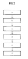
- the method according to the invention for producing the injection system 1 will be explained below with reference to the block diagram in FIG.
- the method according to the invention has the following method steps a-f:
- a housing 2 which has a housing interior 3, which has the fuel K, a first housing passage 4 and a second housing passage 6.
- a piezoelectric actuator 8 is arranged in the housing interior 3.
- the piezoelectric actuator 8 has a head plate 9 which has a first head plate passage 12 and a second head plate passage 13, a controllable piezo stack 11 arranged between the head plate 9 and a bottom plate 10, arranged between the head plate 9 and the bottom plate 10, at least the piezo stack 11 laterally surrounding, sealed enclosure 14 and a arranged in an actuator interior 15 transfer means 16, which has at least one liquid with a liquid pressure P2.
- a first contact device 5 is arranged through the first housing passage 4 and the first head plate passage 12.
- a second contact device 7 is arranged through the second housing passage 6 and the second head plate passage 13.
- the housing interior 3 is sealed off from an exterior space 18 with a predetermined outside pressure P3 by means of a first sealing device 17a, 17b, wherein the first sealing device 17a, 17b surrounds the contact devices 5, 7 in the region of the housing passages 4, 6.
- the actuator interior 15 is sealed relative to the housing interior 3 by means of a second sealing device 19a, 19b, the sealing device 19a, 19b surrounding the contact devices 5, 7 in the region of the head plate passages 12, 13.
- the piezo stack can be cylindrical or square.
Landscapes
- Engineering & Computer Science (AREA)
- Chemical & Material Sciences (AREA)
- Combustion & Propulsion (AREA)
- Mechanical Engineering (AREA)
- General Engineering & Computer Science (AREA)
- Fuel-Injection Apparatus (AREA)
Abstract
Description
- Die Erfindung betrifft ein Einspritzsystem mit einem im Hochdruckraum angeordneten Piezo-Aktor und ein Verfahren zum Herstellen eines solchen Einspritzsystems.
- Einspritzsysteme und insbesondere lecköllose Common-Rail-Einspritzsysteme erfordern ein Steuerelement, wie beispielsweise einen Piezo-Aktor im Hochdruckraum. Um die Arbeitsfähigkeit des Piezo-Aktors auch unter hohen Drücken bis über 2000 bar zu gewährleisten, muss der Druck auch seitlich auf den Piezo-Stapel beziehungsweise Piezo-Keramikkörper wirken können, um die Dehnungsfähigkeit des Piezo-Stapels des Piezo-Aktors zu unterstützen.
- Ein solcher Piezo-Aktor ist beispielsweise in der
WO 02/061856 A1 WO 02/061856 - Außerdem ist der Anmelderin zur Übertragung des Druckes auf den Piezo-Stapel des Piezo-Aktors intern eine Lösung mit einer hermetisch dichten, metallischen Hülse bekannt, die zwischen dem Piezo-Stapel und der Hülse einen Aktor-Innenraum bereitstellt. In dem Aktor-Innenraum wird ein Füllstoff, z.B. ein Silikonöl, zur Übertragung der hydraulischen Kräfte auf die Seitenflächen des Piezo-Keramikkörpers vorgesehen. Diese der Anmelderin intern bekannte Lösung hat allerdings den Nachteil, dass die Abdichtung zwischen dem Piezo-Stapel und der Hülse an der Stelle, an welcher eine elektrische Pindurchführung oder Kontaktvorrichtung zur Kontaktierung und Steuerung des Piezo-Stapels durch die Abdichtung geführt ist, nicht bei längeren Betriebsdauern und insbesondere nicht bei hohen Drücken, wie 2000 bar, hermetisch dicht bleibt. Somit besteht bei einer Undichtheit die Gefahr, dass der Füllstoff aus dem Aktor-Innenraum austreten könnte. Ein Austreten des Füllstoffs könnte den Piezo-Aktor und damit das Einspritzsystem betriebsunfähig machen.
- Eine Aufgabe der vorliegenden Erfindung besteht daher darin, ein Einspritzsystem mit einem im Hochdruckraum angeordneten Piezo-Aktor bereitzustellen, das eine hermetische und insbesondere langzeitstabile Abdichtung des Aktor-Innenraums, insbesondere im Bereich der Durchführung der Kontaktvorrichtung, sicherstellt.
- Eine weitere Aufgabe ist es, eine temperaturstabile Abdichtung des Aktor-Innenraums sicherzustellen.
- Erfindungsgemäß wird zumindest eine dieser gestellten Aufgaben durch ein Einspritzsystem mit den Merkmalen des Patentanspruchs 1 und/oder durch ein Verfahren zum Herstellen eines Einspritzsystems mit den Merkmalen des Patentanspruchs 18 gelöst.
- Demnach wird erfindungsgemäß ein Einspritzsystem zum Einspritzen von Kraftstoff mit einem vorbestimmten Kraftstoffdruck vorgeschlagen, das aufweist:
- ein Gehäuse, welches einen Gehäuseinnenraum, der den Kraftstoff aufweist, einen ersten Gehäusedurchlass und einen zweiten Gehäusedurchlass aufweist,
- einen in dem Gehäuseinnenraum angeordneten Piezo-Aktor, der eine Kopfplatte, welche einen ersten Kopfplattendurchlass und einen zweiten Kopfplattendurchlass aufweist, einen zwischen der Kopfplatte und der Bodenplatte angeordneten, steuerbaren Piezo-Stapel, eine zwischen der Kopfplatte und der Bodenplatte angeordnete, zumindest den Piezo-Stapel seitlich umgebende, dichte Umhüllung und ein in einem Aktor-Innenraum angeordnetes Übertragungsmittel aufweist, welches zumindest eine Flüssigkeit mit einem Flüssigkeitsdruck aufweist,
- eine erste Kontaktvorrichtung, welche durch den ersten Gehäusedurchlass und den ersten Kopfplattendurchlass geführt ist,
- eine zweite Kontaktvorrichtung, welche durch den zweiten Gehäusedurchlass und den zweiten Kopfplattendurchlass geführt ist,
- eine erste Abdichtvorrichtung, welche die Kontaktvorrichtungen im Bereich der Gehäusedurchlässe umgibt und eine Abdichtung zwischen dem Gehäuseinnenraum und einem Außenraum mit einem vorbestimmten Außenraumdruck, beispielsweise Atmosphärendruck, bereitstellt, und
- eine zweite Abdichtvorrichtung, welche die Kontaktvorrichtungen im Bereich der Kopfplattendurchlässe umgibt und eine Abdichtung zwischen dem Gehäuseinnenraum und dem Aktor-Innenraum bereitstellt.
- Ein Vorteil der vorliegenden Erfindung besteht darin, dass der Aktor-Innenraum gegenüber dem Gehäuseinnenraum oder Hochdruckraum des Einspritzsystems hermetisch dicht ist, so dass kein Stoffaustausch zwischen dem Aktor-Innenraum und dem Gehäuseinnenraum stattfinden kann.
- Das Einspritzsystem der vorliegenden Erfindung stellt eine Funktionstrennung bereit, welche die hermetische Abdichtung des Aktor-Innenraums sicherstellt. Die Abdichtung des Kraftstoffs mit dem Kraftstoffdruck von beispielsweise 2000 bar (erste Funktion) gegenüber dem Außenraum mit Außenraumdruck, beispielsweise Atmosphärendruck, wird durch die erste Abdichtvorrichtung bereitgestellt. Die erste Abdichtvorrichtung hat demnach einen Druckunterschied von nahezu 2000 bar abzudichten. Allerdings muss die erste Abdichtvorrichtung nicht unbedingt eine hermetische Abdichtung sicherstellen, da Kraftstoff stets mit 2000 bar nachgeführt wird. Die zweite Funktion, nämlich das Abdichten des Aktor-Innenraums gegenüber dem Gehäuseinnenraum, wird durch die zweite Abdichtvorrichtung bereitgestellt. Im Gehäuseinnenraum herrscht ein Kraftstoffdruck von beispielsweise 2000 bar, der mittels des Übertragungsmittels, das die Flüssigkeit mit dem Flüssigkeitsdruck beinhaltet, auf den Piezo-Stapel übertragen wird. Folglich herrschen zwischen dem Gehäuseinnenraum und dem Aktor-Innenraum Druckunterschiede, die im Vergleich zu den Druckunterschieden zwischen Gehäuseinnenraum und Außenraum sehr klein sind und beispielsweise maximal 200 bar betragen können. Diese Druckunterschiede sind insbesondere von der Ausgestaltungsform der Umhüllung, beispielsweise als Wellrohr, abhängig. Somit hat die zweite Abdichtvorrichtung im Gegensatz zur ersten Abdichtvorrichtung nur Partialdruckunterschiede, die allenfalls 200 bar betragen können, abzudichten. Infolge der geringen Druckunterschiede, welche die zweite Abdichtvorrichtung abzudichten hat, ist der Aktor-Innenraum hermetisch dicht. Insbesondere kann diese Dichtheit auch für lange Betriebsdauern, und insbesondere für beim Betrieb auftretende Temperaturen und Temperaturunterschiede sichergestellt werden.
- Vorteilhafte Ausgestaltungen und Weiterbildungen der Erfindung ergeben sich aus den Unteransprüchen sowie der Beschreibung unter Bezugnahme auf die Zeichnungen.
- Gemäß einer bevorzugten Ausgestaltung der Erfindung ist das Übertragungsmittel dazu geeignet, den außen an der Umhüllung anliegenden Kraftstoffdruck auf den Piezo-Stapel zu übertragen.
- Gemäß einer bevorzugten Weiterbildung der Erfindung stellt der steuerbare Piezo-Stapel einen Hub in Abhängigkeit einer Steuerspannung zum Betätigen einer Düsennadel bereit.
- Gemäß einer weiteren bevorzugten Weiterbildung kontaktieren die erste Kontaktvorrichtung und die zweite Kontaktvorrichtung den Piezo-Stapel zur Steuerung des Piezo-Stapels. Dabei kontaktiert beispielsweise die erste Kontaktvorrichtung eine erste Außenelektrode des Piezo-Stapels und die zweite Kontaktvorrichtung kontaktiert eine zweite Außenelektrode des Piezo-Stapels. Zur Steuerung des Piezo-Stapels wird die erste Kontaktvorrichtung auf ein erstes elektrisches Potenzial und die zweite Kontaktvorrichtung auf ein zweites elektrisches Potenzial gesetzt. Dazu ist beispielweise die erste Kontaktvorrichtung mit einem Pluspol einer Spannungsversorgung und die zweite Kontaktvorrichtung mit einem Minuspol der Spannungsversorgung verbunden. Die Differenz zwischen dem ersten elektrischen Potenzial und dem zweiten elektrischen Potenzial bildet die Steuerspannung aus.
- Gemäß einer weiteren bevorzugten Ausgestaltung ist der Aktor-Innenraum durch die Bodenplatte, die Kopfplatte, die Umhüllung und durch den Piezo-Stapel begrenzt.
- Gemäß einer weiteren bevorzugten Weiterbildung weist das Gehäuse eine Zufuhrvorrichtung zum Zuführen des Kraftstoffs mit dem vorbestimmten Kraftstoffdruck in den Gehäuseinnenraum auf.
- Gemäß einer weiteren bevorzugten Ausgestaltung weist die erste Abdichtvorrichtung ein erstes O-Ring-förmiges Dichtelement, welches die erste Kontaktvorrichtung im Bereich des ersten Gehäusedurchlasses abdichtend umgibt, und ein zweites O-Ring-förmiges Dichtelement auf, welches die zweite Kontaktvorrichtung im Bereich des zweiten Gehäusedurchlasses abdichtend umgibt.
- Gemäß einer weiteren bevorzugten Ausgestaltung sind/ist das erste O-Ring-förmige Dichtelement und/oder das zweite O-Ring-förmige Dichtelement aus einem Kunststoff, insbesondere aus einem Elastomer, ausgebildet.
- Gemäß einer weiteren bevorzugten Ausgestaltung weist die zweite Abdichtvorrichtung ein erstes Abdichtelement, welches die erste Kontaktvorrichtung im Bereich des ersten Kopfplattendurchlasses abdichtend umgibt, und ein zweites Abdichtelement auf, welches die zweite Kontaktvorrichtung im Bereich des zweiten Kopfplattendurchlasses dichtend umgibt.
- Gemäß einer weiteren bevorzugten Ausgestaltung bestehen das erste Abdichtelement und/oder das zweite Abdichtelement aus einem Glas. Glas als Abdichtelement zwischen dem Aktor-Innenraum und dem Gehäuseinnenraum hat die vorteilhafte Eigenschaft, sehr temperaturstabil zu sein. Damit wird die Dichtheit des Aktor-Innenraums selbst bei extremen Temperaturschwankungen und/oder sehr langen Belastungen bei hoher Temperatur sichergestellt.
- Gemäß einer weiteren bevorzugten Ausgestaltung ist der Kraftstoffdruck im Gehäuseinnenraum größer als 1500 bar, insbesondere größer als 2000 bar.
- Gemäß einer weiteren bevorzugten Ausgestaltung entsteht bei der Übertragung des Kraftstoffdruckes auf den Piezo-Stapel ein Druckunterschied zwischen dem Kraftstoffdruck und dem Flüssigkeitsdruck im Aktor-Innenraum, der kleiner oder gleich 200 bar ist. Ein Druckunterschied von 200 bar ergibt sich nur bei extremen Randbedingungen, so dass im Allgemeinen der Kraftstoffdruck und der Flüssigkeitsdruck nahezu gleich sind. Somit existiert ein Partialdruckunterschied zwischen dem Kraftstoffdruck und dem Flüssigkeitsdruck, der im Allgemeinen nahezu Null ist, so dass infolge der erfindungsgemäßen Funktionstrennung von hermetischer Abdichtung und der Abdichtung des Kraftstoffdruckes gegen Atmosphärendruck Glas als hermetisch abdichtendes Dichtmittel zwischen Aktor-Innenraum und Gehäuseinnenraum verwendet werden kann.
- Gemäß einer weiteren bevorzugten Weiterbildung weist das Übertragungsmittel die Flüssigkeit und zumindest einen vorgeformten Körper, der insbesondere aus einer Keramik besteht, auf.
- Gemäß einer weiteren bevorzugten Ausgestaltung ist die Umhüllung als ein Wellrohr ausgebildet, welches eine Vielzahl von Wellen aufweist und insbesondere metallisch ist.
- Gemäß einer weiteren bevorzugten Ausgestaltung ist die Flüssigkeit temperaturbeständig und/oder wärmeleitend und/oder elektrisch isolierend. Vorteilhafterweise ist die Flüssigkeit temperaturbeständig, so dass sich Temperaturschwankungen nicht auf die Eigenschaften der Flüssigkeit auswirken. Vorteilhafterweise ist die Flüssigkeit auch wärmeleitend, so dass keine wesentlichen Dehnungsunterschiede bei der Umhüllung und dem Piezo-Stapel bei einer Temperaturänderung auftreten können. Weiterhin ist die Flüssigkeit auch vorzugsweise elektrisch isolierend, so dass kein elektrischer Überschlag zwischen der Außenelektrode des Piezo-Stapels und der metallischen Umhüllung entstehen kann. Vorzugsweise ist die Flüssigkeit ein Silikonöl.
- Gemäß einer weiteren bevorzugten Ausgestaltung ist das Einspritzsystem ein Common-Rail-Einspritzsystem.
- Die Erfindung wird nachfolgend anhand der in den schematischen Figuren der angegebenen Ausführungsbeispiele näher erläutert. Es zeigen:
- Fig. 1
- eine schematische Längsschnittansicht eines bevorzugten Ausführungsbeispiels des erfindungsgemäßen Einspritzsystems; und
- Fig. 2
- ein schematisches Ablaufdiagramm des erfindungsgemäßen Verfahrens zur Herstellung eines Einspritzsystems.
- In allen Figuren sind gleiche bzw. funktionsgleiche Elemente und Einheiten - sofern nichts anderes angegeben ist - mit denselben Bezugszeichen versehen worden.
- In Fig. 1 ist eine schematische Längsschnittansicht eines bevorzugten Ausführungsbeispiels des erfindungsgemäßen Einspritzsystems 1 zum Einspritzen von Kraftstoff K mit einem vorbestimmten Kraftstoffdruck P1 in eine Düse oder ein Ventil (nicht gezeigt) abgebildet.
- Das Einspritzsystem 1 weist ein Gehäuse 2 auf, das einen Gehäuseinnenraum 3, der den Kraftstoff K beinhaltet, einen ersten Gehäusedurchlass 4 zur Durchführung einer ersten Kontaktvorrichtung 5 und einen zweiten Gehäusedurchlass 6 zur Durchführung einer zweiten Kontaktvorrichtung 7 aufweist.
- In dem Gehäuseinnenraum 3 ist ein Piezo-Aktor 8 angeordnet. Der Piezo-Aktor 8 weist eine Kopfplatte 9, eine Bodenplatte 10, einen Piezo-Stapel 11 und eine Umhüllung 14 auf. Die Kopfplatte 9 hat einen ersten Kopfplattendurchlass 12 zur Durchführung der ersten Kontaktvorrichtung 5 und einen zweiten Kopfplattendurchlass 13 zur Durchführung der zweiten Kontaktvorrichtung 7. Der Piezo-Stapel 11 ist mittels einer Steuerspannung U steuerbar und zwischen der Kopfplatte 9 und der Bodenplatte 10 angeordnet. Der steuerbare Piezo-Stapel 11 stellt einen Hub in Abhängigkeit der Steuerspannung U zum Betätigen einer Düsennadel (nicht gezeigt) bereit.
- Zwischen der Kopfplatte 9 und der Bodenplatte 10 ist eine zumindest den Piezo-Stapel 11 seitlich umgebende, dichte Umhüllung 14 angeordnet. Die Umhüllung 14 ist vorzugsweise als ein Wellrohr ausgebildet, das eine Vielzahl von Wellen aufweist und insbesondere metallisch ist.
- Die Kopfplatte 9, die Bodenplatte 10, die Umhüllung 14 und der Piezo-Stapel 11 begrenzen einen Aktor-Innenraum 15. In dem Aktor-Innenraum 15 ist ein Übertragungsmittel 16 angeordnet, welches dazu geeignet ist, den außen an der Umhüllung 14 anliegenden Kraftstoffdruck P1 auf den Piezo-Stapel 11 zu übertragen. Dazu weist das Übertragungsmittel 17 zumindest eine Flüssigkeit F mit einem Flüssigkeitsdruck P2 auf. Der Kraftstoffdruck P1 ist vorzugsweise größer als 1500 bar, insbesondere größer als 2000 bar. Bei der Übertragung des Kraftstoffdruckes P1 auf den Piezo-Stapel 11 wird der Druck auf das Übertragungselement 16 übertragen, so dass der Flüssigkeitsdruck P2 im Wesentlichen dem Kraftstoffdruck P1 entspricht. Der Druckunterschied zwischen dem Kraftstoffdruck P1 und dem Flüssigkeitsdruck P2 beträgt höchstens 200 bar. Insbesondere ist die Flüssigkeit F temperaturbeständig und/oder wärmeleitend und/oder elektrisch isolierend. Beispielsweise ist die Flüssigkeit F ein Silikonöl.
- Die erste Kontaktvorrichtung 5 wird durch den ersten Gehäusedurchlass 4 und den ersten Kopfplattendurchlass 12 geführt. Analog wird die zweite Kontaktvorrichtung 7 durch den zweiten Gehäusedurchlass 6 und den zweiten Kopfplattendurchlass 13 geführt. Die beiden Kontaktvorrichtungen 5, 7 sind insbesondere aus Metall oder Invar. Die erste Kontaktvorrichtung 5 und die zweite Kontaktvorrichtung 7 kontaktieren den Piezo-Stapel 11 zu dessen Steuerung. Dabei wird die erste Kontaktvorrichtung 5 auf ein erstes elektrisches Potenzial PT1 und die zweite Kontaktvorrichtung 7 auf ein zweites elektrisches Potenzial PT2 gesetzt, wobei die Differenz zwischen dem ersten elektrischen Potenzial PT1 und dem zweiten elektrischen Potenzial PT2 die Steuerspannung U ausbildet.
- Weiter weist das Einspritzsystem 1 eine erste Abdichtvorrichtung 17a, 17b auf, welche die Kontaktvorrichtungen 5, 7 im Bereich der Gehäusedurchlässe 4, 6 umgibt und eine Abdichtung zwischen dem Gehäuseinnenraum 3 und einem Außenraum 18 mit einem vorbestimmten Außenraumdruck P3 bereitstellt. Der Außenraumdruck P3 ist beispielsweise der Atmosphärendruck.
- Die erste Abdichtvorrichtung 17a, 17b weist ein erstes O-Ring-förmiges Dichtelement 17a, welches die erste Kontaktvorrichtung 5 im Bereich des ersten Gehäusedurchlasses 4 abdichtend umgibt, und ein zweites O-Ring-förmiges Dichtelement 17b auf, welches die zweite Kontaktvorrichtung 7 im Bereich des zweiten Gehäusedurchlasses 6 abdichtend umgibt. Die O-Ringförmigen Dichtelemente 17a, 17b sind beispielsweise aus Kunststoff, insbesondere aus einem Elastomer ausgebildet.
- Weiterhin weist das Einspritzsystem 1 eine zweite Abdichtvorrichtung 19a, 19b auf, welche die Kontaktvorrichtungen 5, 7 im Bereich der Kopfplattendurchlässe 12, 13 umgibt und eine Abdichtung zwischen dem Gehäuseinnenraum 3 und dem Aktor-Innenraum 15 bereitstellt. Die zweite Abdichtvorrichtung 19a, 19b weist ein erstes Abdichtelement 19a, welches die erste Kontaktvorrichtung 5 im Bereich des ersten Kopfplattendurchlasses 12 abdichtend umgibt, und ein zweites Abdichtelement 19b auf, welches die zweite Kontaktvorrichtung 7 im Bereich des zweiten Kopfplattendurchlasses 12 abdichtend umgibt. Die Abdichtelemente 19a, 19b sind insbesondere aus Gründen der Temperaturstabilität aus Glas.
- Außerdem weist das Gehäuse 2 eine Zuführvorrichtung 20 auf, mittels welcher der Kraftstoff K mit dem vorbestimmten Kraftstoffdruck P1 in den Gehäuseinnenraum 3 zugeführt wird. Die Zuführvorrichtung 20 ist beispielsweise als ein Stutzen ausgebildet. Weiter weist das Einspritzsystem 1 ein Kraftübertragungselement 21 auf, welches das Gehäuse 2 mit dem Piezo-Aktor 8 koppelt.
- Nachfolgend wird das erfindungsgemäße Verfahren zum Herstellen des Einspritzsystems 1 anhand des Blockschaltbildes in Fig. 2 erläutert. Das erfindungsgemäße Verfahren weist folgende Verfahrensschritte a-f auf:
- Es wird ein Gehäuse 2 bereitgestellt, welches einen Gehäuseinnenraum 3, der den Kraftstoff K aufweist, einen ersten Gehäusedurchlass 4 und einen zweiten Gehäusedurchlass 6 aufweist.
- In dem Gehäuseinnenraum 3 wird ein Piezo-Aktor 8 angeordnet. Der Piezo-Aktor 8 weist eine Kopfplatte 9, welche einen ersten Kopfplattendurchlass 12 und einen zweiten Kopfplattendurchlass 13 aufweist, einen zwischen der Kopfplatte 9 und einer Bodenplatte 10 angeordneten, steuerbaren Piezo-Stapel 11, eine zwischen der Kopfplatte 9 und der Bodenplatte 10 angeordnete, zumindest den Piezo-Stapel 11 seitlich umgebende, dichte Umhüllung 14 und ein in einem Aktor-Innenraum 15 angeordnetes Übertragungsmittel 16 auf, welches zumindest eine Flüssigkeit mit einem Flüssigkeitsdruck P2 aufweist.
- Eine erste Kontaktvorrichtung 5 wird durch den ersten Gehäusedurchlass 4 und den ersten Kopfplattendurchlass 12 angeordnet.
- Eine zweite Kontaktvorrichtung 7 wird durch den zweiten Gehäusedurchlass 6 und den zweiten Kopfplattendurchlass 13 angeordnet.
- Der Gehäuseinnenraum 3 wird gegenüber einem Außenraum 18 mit einem vorbestimmten Außenraumdruck P3 mittels einer ersten Abdichtvorrichtung 17a, 17b abgedichtet, wobei die erste Abdichtvorrichtung 17a, 17b die Kontaktvorrichtungen 5, 7 im Bereich der Gehäusedurchlässe 4, 6 umgibt.
- Der Aktor-Innenraum 15 wird gegenüber dem Gehäuseinnenraum 3 mittels einer zweiten Abdichtvorrichtung 19a, 19b abgedichtet, wobei die Abdichtvorrichtung 19a, 19b die Kontaktvorrichtungen 5, 7 im Bereich der Kopfplattendurchlässe 12, 13 umgibt.
- Obwohl die vorliegenden Erfindung vorstehend anhand der bevorzugten Ausführungsbeispiele beschrieben wurde, ist sie darauf nicht beschränkt, sondern auf vielfältige Art und Weise modifizierbar. Beispielsweise kann der Piezo-Stapel zylindrisch oder auch quadratisch ausgebildet sein.
Claims (18)
- Einspritzsystem (1) zum Einspritzen von Kraftstoff (K) mit einem vorbestimmten Kraftstoffdruck (P1) mit:a) einem Gehäuse (2), welches einen Gehäuseinnenraum (3), der den Kraftstoff (K) aufweist, einen ersten Gehäusedurchlass (4) und einen zweiten Gehäusedurchlass (6) aufweist;b) einem in dem Gehäuseinnenraum (3) angeordneten Piezo-Aktor (8), welcher aufweist:b1) eine Kopfplatte (9), welche einen ersten Kopfplattendurchlass (12) und einen zweiten Kopfplattendurchlass (13) aufweist,b2) einen zwischen der Kopfplatte (9) und einer Bodenplatte (10) angeordneten, steuerbaren Piezo-Stapel (11),b3) eine zwischen der Kopfplatte (9) und der Bodenplatte (10) angeordnete, zumindest den Piezo-Stapel (11) seitlich umgebende, dichte Umhüllung (14), undb4) ein in einem Aktor-Innenraum (15) angeordnetes Übertragungsmittel (16), welches zumindest eine Flüssigkeit mit einem Flüssigkeitsdruck (P2) aufweist;c) einer ersten Kontaktvorrichtung (5), welche durch den ersten Gehäusedurchlass (4) und den ersten Kopfplattendurchlass (12) geführt ist;d) einer zweiten Kontaktvorrichtung (7), welche durch den zweiten Gehäusedurchlass (6) und den zweiten Kopfplattendurchlass (13) geführt ist;e) einer ersten Abdichtvorrichtung (17a,17b), welche die Kontaktvorrichtungen (5, 7) im Bereich der Gehäusedurchlässe (4, 6) umgibt und eine Abdichtung zwischen dem Gehäuseinnenraum (3) und einem Außenraum (18) mit einem vorbestimmten Außenraumdruck (P3) bereitstellt; und mitf) einer zweiten Abdichtvorrichtung (19a,19b), welche die Kontaktvorrichtungen (5, 7) im Bereich der Kopfplattendurchlässe (12, 13) umgibt und eine Abdichtung zwischen dem Gehäuseinnenraum (3) und dem Aktor-Innenraum (15) bereitstellt.
- Einspritzsystem nach Anspruch 1,
dadurch gekennzeichnet,
dass das Übertragungsmittel (16) dazu geeignet ist, den außen an der Umhüllung (14) anliegenden Kraftstoffdruck (P1) auf den Piezo-Stapel (11) zu übertragen. - Einspritzsystem nach Anspruch 1 oder 2,
dadurch gekennzeichnet,
dass der steuerbare Piezo-Stapel (11) einen Hub in Abhängigkeit einer Steuerspannung (U) zum Betätigen einer Düsennadel bereitstellt. - Einspritzsystem nach Anspruch 3,
dadurch gekennzeichnet,
dass die erste Kontaktvorrichtung (5) und die zweite Kontaktvorrichtung (7) den Piezo-Stapel (11) zur Steuerung des Piezo-Stapels (11) kontaktieren, wobei die erste Kontaktvorrichtung (5) auf ein erstes elektrisches Potenzial (PT1) und die zweite Kontaktvorrichtung (7) auf ein zweites elektrisches Potenzial (PT2) gesetzt wird, wobei die Differenz zwischen dem ersten elektrischen Potenzial (PT1) und dem zweiten elektrischen Potenzial (PT2) die Steuerspannung (U) ausbildet. - Einspritzsystem nach einem oder mehreren der vorstehenden Ansprüche,
dadurch gekennzeichnet,
dass der Aktor-Innenraum (15) durch die Kopfplatte (9), die Bodenplatte (10), die Umhüllung (14) und durch den Piezo-Stapel (11) begrenzt ist. - Einspritzsystem nach einem oder mehreren der vorstehenden Ansprüche,
dadurch gekennzeichnet,
dass das Gehäuse (2) eine Zuführvorrichtung (20) zum Zuführen des Kraftstoffs (K) mit dem vorbestimmten Kraftstoffdruck (P1) in den Gehäuseinnenraum (3) aufweist. - Einspritzsystem nach einem oder mehreren der vorstehenden Ansprüche,
dadurch gekennzeichnet,
dass die erste Abdichtvorrichtung (17a, 17b) ein erstes O-Ring-förmiges Dichtelement (17a), welches die erste Kontaktvorrichtung (5) im Bereich des ersten Gehäusedurchlasses (4) abdichtend umgibt, und ein zweites O-Ring-förmiges Dichtelement (17b) ausweist, welches die zweite Kontaktvorrichtung (7) im Bereich des zweiten Gehäusedurchlasses (6) abdichtend umgibt. - Einspritzsystem nach Anspruch 7,
dadurch gekennzeichnet,
dass das erste O-Ring-förmige Dichtelement (17a) und/oder das zweite O-Ring-förmige Dichtelement (17b) aus einem Kunststoff, insbesondere aus einem Elastomer, ausgebildet sind/ist. - Einspritzsystem nach einem oder mehreren der vorstehenden Ansprüche,
dadurch gekennzeichnet,
dass die zweite Abdichtvorrichtung (19a, 19b) ein erstes Abdichtelement (19a), welches die erste Kontaktvorrichtung (5) im Bereich des ersten Kopfplattendurchlasses (12) abdichtend umgibt, und ein zweites Abdichtelement (19b) aufweist, welches die zweite Kontaktvorrichtung (7) im Bereich des zweiten Kopfplattendurchlasses (12) abdichtend umgibt. - Einspritzsystem nach Anspruch 9,
dadurch gekennzeichnet,
dass das erste Abdichtelement (19a) und/oder das zweite Abdichtelement (19b) aus einem Glas bestehen. - Einspritzsystem nach einem oder mehreren der vorstehenden Ansprüche,
dadurch gekennzeichnet,
dass der Kraftstoffdruck (P1) größer als 1500 bar, insbesondere größer als 2000 bar ist. - Einspritzsystem nach einem oder mehreren der vorstehenden Ansprüche,
dadurch gekennzeichnet,
dass bei der Übertragung des Kraftstoffdruckes (P1) auf den Piezo-Stapel (11) ein Druckunterschied zwischen dem Kraftstoffdruck (P1) und dem Flüssigkeitsdruck (P2) im Aktor-Innenraum (15) entsteht, der kleiner gleich 200 bar ist. - Einspritzsystem nach einem oder mehreren der vorstehenden Ansprüche,
dadurch gekennzeichnet,
dass das Übertragungsmittel (16) die Flüssigkeit (F) und zumindest einen vorgeformten Körper, der insbesondere aus einer Keramik besteht, aufweist. - Einspritzsystem nach einem oder mehreren der vorstehenden Ansprüche,
dadurch gekennzeichnet,
dass die Umhüllung (14) als ein Wellrohr ausgebildet ist, welches eine Vielzahl von Wellen aufweist und insbesondere metallisch ist. - Einspritzsystem nach einem oder mehreren der vorstehenden Ansprüche,
dadurch gekennzeichnet,
dass die Flüssigkeit (F) temperaturbeständig und/oder wärmeleitend und/oder elektrisch isolierend ist. - Einspritzsystem nach Anspruch 15,
dadurch gekennzeichnet,
dass die Flüssigkeit (F) als ein Silikonöl ausgebildet ist. - Einspritzsystem nach einem oder mehreren der vorstehenden Ansprüche,
dadurch gekennzeichnet,
dass das Einspritzsystem (1) als ein Common-Rail-Einspritzsystem ausgebildet ist. - Verfahren zum Herstellen eines Einspritzsystems (1) zum Einspritzen von Kraftstoff (K) mit einem vorbestimmten Kraftstoffdruck (P1) nach einem oder mehreren der vorstehenden Ansprüche mit den Schritten:a) Bereitstellen eines Gehäuses (2), welches einen Gehäuseinnenraum (3), der den Kraftstoff (K) aufweist, einen ersten Gehäusedurchlass (4) und einen zweiten Gehäusedurchlass (6) aufweist;b) Anordnen eines Piezo-Aktors (8) in dem Gehäuseinnenraum (3), welcher aufweist:b1) eine Kopfplatte (9), welche einen ersten Kopfplattendurchlass (12) und einen zweiten Kopfplattendurchlass (13) aufweist,b2) einen zwischen der Kopfplatte (9) und einer Bodenplatte (10) angeordneten, steuerbaren Piezo-Stapel (11),b3) eine zwischen der Kopfplatte (9) und der Bodenplatte (10) angeordnete, zumindest den Piezo-Stapel (11) seitlich umgebende, dichte Umhüllung (14), undb4) ein in einem Aktor-Innenraum (15) angeordnetes Übertragungsmittel (16), welches zumindest eine Flüssigkeit mit einem Flüssigkeitsdruck (P2) aufweist;c) Anordnen einer ersten Kontaktvorrichtung (5) durch den ersten Gehäusedurchlass (4) und den ersten Kopfplattendurchlass (12);d) Anordnen einer zweiten Kontaktvorrichtung (7) durch den zweiten Gehäusedurchlass (6) und den zweiten Kopfplattendurchlass (13);e) Abdichten des Gehäuseinnenraums (3) gegenüber einem Außenraum (18) mit einem vorbestimmten Außenraumdruck (P3) mittels einer ersten Abdichtvorrichtung (17a, 17b), welche die Kontaktvorrichtungen (5, 7) im Bereich der Gehäusedurchlässe (4, 6) umgibt; undf) Abdichten des Aktor-Innenraums (15) gegenüber dem Gehäuseinnenraum (3) mittels einer zweiten Abdichtvorrichtung (19a, 19b), welche die Kontaktvorrichtungen (5, 7) im Bereich der Kopfplattendurchlässe (12, 13) umgibt.
Priority Applications (3)
| Application Number | Priority Date | Filing Date | Title |
|---|---|---|---|
| DE502006007633T DE502006007633D1 (de) | 2006-05-09 | 2006-05-09 | Kraftstoffeinspritzsystem und ein Verfahren zum Herstellen dieses Einspritzsystems |
| EP06009556A EP1854992B1 (de) | 2006-05-09 | 2006-05-09 | Kraftstoffeinspritzsystem und ein Verfahren zum Herstellen dieses Einspritzsystems |
| US11/745,798 US8038079B2 (en) | 2006-05-09 | 2007-05-08 | Injection system and a method for producing an injection system |
Applications Claiming Priority (1)
| Application Number | Priority Date | Filing Date | Title |
|---|---|---|---|
| EP06009556A EP1854992B1 (de) | 2006-05-09 | 2006-05-09 | Kraftstoffeinspritzsystem und ein Verfahren zum Herstellen dieses Einspritzsystems |
Publications (2)
| Publication Number | Publication Date |
|---|---|
| EP1854992A1 true EP1854992A1 (de) | 2007-11-14 |
| EP1854992B1 EP1854992B1 (de) | 2010-08-11 |
Family
ID=37022928
Family Applications (1)
| Application Number | Title | Priority Date | Filing Date |
|---|---|---|---|
| EP06009556A Ceased EP1854992B1 (de) | 2006-05-09 | 2006-05-09 | Kraftstoffeinspritzsystem und ein Verfahren zum Herstellen dieses Einspritzsystems |
Country Status (3)
| Country | Link |
|---|---|
| US (1) | US8038079B2 (de) |
| EP (1) | EP1854992B1 (de) |
| DE (1) | DE502006007633D1 (de) |
Cited By (1)
| Publication number | Priority date | Publication date | Assignee | Title |
|---|---|---|---|---|
| CN114270550A (zh) * | 2019-08-27 | 2022-04-01 | Tdk电子股份有限公司 | 具有电陶瓷的构件的装置 |
Families Citing this family (1)
| Publication number | Priority date | Publication date | Assignee | Title |
|---|---|---|---|---|
| EP2866149A4 (de) * | 2012-06-26 | 2016-05-18 | Mitsubishi Electric Corp | Ausrüstungsverwaltungssystem und -programm |
Citations (5)
| Publication number | Priority date | Publication date | Assignee | Title |
|---|---|---|---|---|
| US4471256A (en) * | 1982-06-14 | 1984-09-11 | Nippon Soken, Inc. | Piezoelectric actuator, and valve apparatus having actuator |
| WO2002061856A1 (en) | 2001-02-01 | 2002-08-08 | Delphi Technologies, Inc. | Method of assembling an actuator arrangement |
| EP1420467A2 (de) * | 2002-10-28 | 2004-05-19 | Siemens Aktiengesellschaft | Aktor mit einer Durchführungsöffnung, die bei der Umspritzung gegen eindringenden Kunststoff abgedichtet ist |
| EP1431568A2 (de) * | 2002-12-19 | 2004-06-23 | Robert Bosch Gmbh | Brennstoffeinspritzventil |
| US20060038030A1 (en) * | 2004-08-20 | 2006-02-23 | Klaus Plecher | Actuator for a fuel injector of an internal combustion engine |
Family Cites Families (7)
| Publication number | Priority date | Publication date | Assignee | Title |
|---|---|---|---|---|
| DE19932760A1 (de) * | 1999-07-14 | 2001-01-18 | Bosch Gmbh Robert | Brennstoffeinspritzventil |
| JP4356268B2 (ja) * | 2000-06-26 | 2009-11-04 | 株式会社デンソー | 燃料噴射装置 |
| DE50305852D1 (de) * | 2002-04-04 | 2007-01-11 | Siemens Ag | Einspritzventil |
| DE10245109A1 (de) * | 2002-09-27 | 2004-04-08 | Siemens Ag | Injektor, insbesondere Kraftstoff-Einspritzventil, mit einem piezoelektrischen Aktor |
| US7111500B2 (en) * | 2002-12-26 | 2006-09-26 | Ulvac Inc. | Analysis method using piezoelectric resonator |
| US6983895B2 (en) * | 2003-10-09 | 2006-01-10 | Siemens Aktiengesellschaft | Piezoelectric actuator with compensator |
| DE102004042353B4 (de) * | 2004-08-20 | 2008-10-09 | Continental Automotive Gmbh | Abdichtungsanordnung eines Piezoaktors für ein Kraftstoffeinspritzventil einer Brennkraftmaschine |
-
2006
- 2006-05-09 DE DE502006007633T patent/DE502006007633D1/de active Active
- 2006-05-09 EP EP06009556A patent/EP1854992B1/de not_active Ceased
-
2007
- 2007-05-08 US US11/745,798 patent/US8038079B2/en not_active Expired - Fee Related
Patent Citations (5)
| Publication number | Priority date | Publication date | Assignee | Title |
|---|---|---|---|---|
| US4471256A (en) * | 1982-06-14 | 1984-09-11 | Nippon Soken, Inc. | Piezoelectric actuator, and valve apparatus having actuator |
| WO2002061856A1 (en) | 2001-02-01 | 2002-08-08 | Delphi Technologies, Inc. | Method of assembling an actuator arrangement |
| EP1420467A2 (de) * | 2002-10-28 | 2004-05-19 | Siemens Aktiengesellschaft | Aktor mit einer Durchführungsöffnung, die bei der Umspritzung gegen eindringenden Kunststoff abgedichtet ist |
| EP1431568A2 (de) * | 2002-12-19 | 2004-06-23 | Robert Bosch Gmbh | Brennstoffeinspritzventil |
| US20060038030A1 (en) * | 2004-08-20 | 2006-02-23 | Klaus Plecher | Actuator for a fuel injector of an internal combustion engine |
Cited By (1)
| Publication number | Priority date | Publication date | Assignee | Title |
|---|---|---|---|---|
| CN114270550A (zh) * | 2019-08-27 | 2022-04-01 | Tdk电子股份有限公司 | 具有电陶瓷的构件的装置 |
Also Published As
| Publication number | Publication date |
|---|---|
| US8038079B2 (en) | 2011-10-18 |
| EP1854992B1 (de) | 2010-08-11 |
| US20080001010A1 (en) | 2008-01-03 |
| DE502006007633D1 (de) | 2010-09-23 |
Similar Documents
| Publication | Publication Date | Title |
|---|---|---|
| EP1906464B1 (de) | Piezoaktor mit einer Ummantelung, zur Anordnung in einem Piezoinjektor | |
| EP1984957B1 (de) | Piezokeramischer vielschicht-aktor, verfahren zum herstellen eines piezokeramischen vielschicht-aktors und einspritzsystem | |
| EP1714024B1 (de) | Brennstoffsystemteil mit einer kabeldurchführung | |
| WO2007128764A1 (de) | Piezo-aktor, verfahren zum herstellen eines piezo-aktors und einspritzsystem mit einem solchen | |
| DE602005003441T2 (de) | Piezoelektrischer Aktor | |
| EP1854992B1 (de) | Kraftstoffeinspritzsystem und ein Verfahren zum Herstellen dieses Einspritzsystems | |
| EP1920476B1 (de) | Anordnung mit einem piezoaktor | |
| EP2018672B1 (de) | Injektor mit einem piezoelektrischen aktor für eine brennkraftmaschine | |
| EP1962351A1 (de) | Piezoaktormodul mit einer Kabeldurchführung | |
| DE102005046122A1 (de) | Brennstoffeinspritzventil | |
| EP2031669B1 (de) | Piezoaktormodul mit einer Umhüllung des Piezoaktors und ein Verfahren zu dessen Herstellung | |
| WO2007118726A1 (de) | Aktormodul | |
| EP1909339B1 (de) | Aktormodul mit einem umhüllten Piezoaktor | |
| EP0492296A1 (de) | Heisskanal-Umlenkeinrichtung für Spritzgiesswerkzeug | |
| EP1912265B1 (de) | Aktormodul mit einem umhüllten Piezoaktor | |
| EP2013923B1 (de) | Piezoaktor mit einer ummantelung | |
| EP1972778B1 (de) | Kabeldurchführungen für ein Piezoaktormodul | |
| WO2007033909A1 (de) | Anordnung mit einem piezoaktor und ein verfahren zu dessen herstellung | |
| WO2005076378A1 (de) | Piezoaktor mit einer isolierschicht | |
| EP2034532A1 (de) | Piezoaktormodul mit einem Schutzschichtsystem und ein Verfahren zu dessen Herstellung | |
| DE102006043709A1 (de) | Anordnung eines Piezoaktors in einem Gehäuse | |
| DE102009046306A1 (de) | Piezoelektrischer Aktor | |
| DE102008018342A1 (de) | Piezoaktormodul für eine von einem Medium umströmte Anordnung | |
| DE102006051328A1 (de) | Piezoaktormodul oder Piezoaktor mit einem ummantelnden Schutzschichtsystem | |
| EP2034531A2 (de) | Piezoaktormodul mit einem Schutzschichtsystem und ein Verfahren zu dessen Herstellung |
Legal Events
| Date | Code | Title | Description |
|---|---|---|---|
| PUAI | Public reference made under article 153(3) epc to a published international application that has entered the european phase |
Free format text: ORIGINAL CODE: 0009012 |
|
| AK | Designated contracting states |
Kind code of ref document: A1 Designated state(s): AT BE BG CH CY CZ DE DK EE ES FI FR GB GR HU IE IS IT LI LT LU LV MC NL PL PT RO SE SI SK TR |
|
| AX | Request for extension of the european patent |
Extension state: AL BA HR MK YU |
|
| 17P | Request for examination filed |
Effective date: 20071214 |
|
| 17Q | First examination report despatched |
Effective date: 20080204 |
|
| RAP1 | Party data changed (applicant data changed or rights of an application transferred) |
Owner name: CONTINENTAL AUTOMOTIVE GMBH |
|
| AKX | Designation fees paid |
Designated state(s): DE FR |
|
| GRAP | Despatch of communication of intention to grant a patent |
Free format text: ORIGINAL CODE: EPIDOSNIGR1 |
|
| GRAS | Grant fee paid |
Free format text: ORIGINAL CODE: EPIDOSNIGR3 |
|
| GRAA | (expected) grant |
Free format text: ORIGINAL CODE: 0009210 |
|
| AK | Designated contracting states |
Kind code of ref document: B1 Designated state(s): DE FR |
|
| REF | Corresponds to: |
Ref document number: 502006007633 Country of ref document: DE Date of ref document: 20100923 Kind code of ref document: P |
|
| PLBE | No opposition filed within time limit |
Free format text: ORIGINAL CODE: 0009261 |
|
| STAA | Information on the status of an ep patent application or granted ep patent |
Free format text: STATUS: NO OPPOSITION FILED WITHIN TIME LIMIT |
|
| 26N | No opposition filed |
Effective date: 20110512 |
|
| REG | Reference to a national code |
Ref country code: DE Ref legal event code: R097 Ref document number: 502006007633 Country of ref document: DE Effective date: 20110512 |
|
| REG | Reference to a national code |
Ref country code: FR Ref legal event code: PLFP Year of fee payment: 11 |
|
| REG | Reference to a national code |
Ref country code: FR Ref legal event code: PLFP Year of fee payment: 12 |
|
| REG | Reference to a national code |
Ref country code: FR Ref legal event code: PLFP Year of fee payment: 13 |
|
| PGFP | Annual fee paid to national office [announced via postgrant information from national office to epo] |
Ref country code: DE Payment date: 20180531 Year of fee payment: 13 |
|
| PGFP | Annual fee paid to national office [announced via postgrant information from national office to epo] |
Ref country code: FR Payment date: 20180522 Year of fee payment: 13 |
|
| REG | Reference to a national code |
Ref country code: DE Ref legal event code: R119 Ref document number: 502006007633 Country of ref document: DE |
|
| PG25 | Lapsed in a contracting state [announced via postgrant information from national office to epo] |
Ref country code: DE Free format text: LAPSE BECAUSE OF NON-PAYMENT OF DUE FEES Effective date: 20191203 |
|
| PG25 | Lapsed in a contracting state [announced via postgrant information from national office to epo] |
Ref country code: FR Free format text: LAPSE BECAUSE OF NON-PAYMENT OF DUE FEES Effective date: 20190531 |