EP1854635B1 - Druckereinheit mit verformbarer Halterung - Google Patents
Druckereinheit mit verformbarer Halterung Download PDFInfo
- Publication number
- EP1854635B1 EP1854635B1 EP07290595A EP07290595A EP1854635B1 EP 1854635 B1 EP1854635 B1 EP 1854635B1 EP 07290595 A EP07290595 A EP 07290595A EP 07290595 A EP07290595 A EP 07290595A EP 1854635 B1 EP1854635 B1 EP 1854635B1
- Authority
- EP
- European Patent Office
- Prior art keywords
- plate
- printing unit
- bar
- adjusting
- rigid
- Prior art date
- Legal status (The legal status is an assumption and is not a legal conclusion. Google has not performed a legal analysis and makes no representation as to the accuracy of the status listed.)
- Not-in-force
Links
- 238000007639 printing Methods 0.000 title claims description 47
- 238000007641 inkjet printing Methods 0.000 claims description 6
- 238000005452 bending Methods 0.000 claims 2
- 239000007787 solid Substances 0.000 claims 1
- 230000003313 weakening effect Effects 0.000 claims 1
- 238000006073 displacement reaction Methods 0.000 description 4
- 239000003086 colorant Substances 0.000 description 2
- BASFCYQUMIYNBI-UHFFFAOYSA-N platinum Chemical compound [Pt] BASFCYQUMIYNBI-UHFFFAOYSA-N 0.000 description 2
- 230000006835 compression Effects 0.000 description 1
- 238000007906 compression Methods 0.000 description 1
- 230000001419 dependent effect Effects 0.000 description 1
- 238000004519 manufacturing process Methods 0.000 description 1
- 229910052697 platinum Inorganic materials 0.000 description 1
Images


Classifications
-
- B—PERFORMING OPERATIONS; TRANSPORTING
- B41—PRINTING; LINING MACHINES; TYPEWRITERS; STAMPS
- B41J—TYPEWRITERS; SELECTIVE PRINTING MECHANISMS, i.e. MECHANISMS PRINTING OTHERWISE THAN FROM A FORME; CORRECTION OF TYPOGRAPHICAL ERRORS
- B41J2/00—Typewriters or selective printing mechanisms characterised by the printing or marking process for which they are designed
- B41J2/005—Typewriters or selective printing mechanisms characterised by the printing or marking process for which they are designed characterised by bringing liquid or particles selectively into contact with a printing material
- B41J2/01—Ink jet
- B41J2/17—Ink jet characterised by ink handling
- B41J2/175—Ink supply systems ; Circuit parts therefor
- B41J2/17503—Ink cartridges
- B41J2/1752—Mounting within the printer
-
- B—PERFORMING OPERATIONS; TRANSPORTING
- B41—PRINTING; LINING MACHINES; TYPEWRITERS; STAMPS
- B41J—TYPEWRITERS; SELECTIVE PRINTING MECHANISMS, i.e. MECHANISMS PRINTING OTHERWISE THAN FROM A FORME; CORRECTION OF TYPOGRAPHICAL ERRORS
- B41J2/00—Typewriters or selective printing mechanisms characterised by the printing or marking process for which they are designed
- B41J2/005—Typewriters or selective printing mechanisms characterised by the printing or marking process for which they are designed characterised by bringing liquid or particles selectively into contact with a printing material
- B41J2/01—Ink jet
- B41J2/21—Ink jet for multi-colour printing
- B41J2/2132—Print quality control characterised by dot disposition, e.g. for reducing white stripes or banding
- B41J2/2135—Alignment of dots
-
- B—PERFORMING OPERATIONS; TRANSPORTING
- B41—PRINTING; LINING MACHINES; TYPEWRITERS; STAMPS
- B41J—TYPEWRITERS; SELECTIVE PRINTING MECHANISMS, i.e. MECHANISMS PRINTING OTHERWISE THAN FROM A FORME; CORRECTION OF TYPOGRAPHICAL ERRORS
- B41J25/00—Actions or mechanisms not otherwise provided for
- B41J25/304—Bodily-movable mechanisms for print heads or carriages movable towards or from paper surface
-
- B—PERFORMING OPERATIONS; TRANSPORTING
- B41—PRINTING; LINING MACHINES; TYPEWRITERS; STAMPS
- B41J—TYPEWRITERS; SELECTIVE PRINTING MECHANISMS, i.e. MECHANISMS PRINTING OTHERWISE THAN FROM A FORME; CORRECTION OF TYPOGRAPHICAL ERRORS
- B41J2202/00—Embodiments of or processes related to ink-jet or thermal heads
- B41J2202/01—Embodiments of or processes related to ink-jet heads
- B41J2202/14—Mounting head into the printer
Definitions
- the present invention relates to a printing unit according to the preamble of claim 1.
- Such printing units are used on inkjet printing machines, a machine generally comprising several printing units arranged in parallel towards the same object to be printed.
- At least four printing units are arranged side by side, each for a primary color and black.
- drops of several colors are superimposed on the support. It is therefore appropriate that the heads of the printing units are rigorously positioned parallel to one another so that the projected drops, after displacement of the printing units by a suitable number of steps, are rigorously superimposed, otherwise the drops are staggered, reducing the quality of the resulting print.
- the printing units are generally mounted on the frame of the machine by means of an adjustable fixing bracket, for example by means of parallel rail systems controlled by screw / nut arrangements.
- the print head is generally adjustable to precisely define the direction of the ink jet.
- the adjustment means of the printing unit are conventionally rail systems on which the head slides. Such systems lack precision and are cumbersome.
- the print heads are placed in cells formed in a support plate.
- the heads are surrounded by cleats fixed to the sheet and thrust screws mounted in the cleats control the position of the nozzles in the cells.
- the position as well as the parallelism of the nozzles are adjusted by means of opposing screws, which requires loosening the screw opposite to the one which must make the displacement.
- Such settings are extremely long and tedious and despite the fact that they must be made only during a change of nozzles, the lightness of the settings makes these settings unreliable over time.
- EP.0.693.382 describes a printing unit of the state of the art.
- the object of the invention is to propose a printing unit comprising precise adjustment means, in particular in several directions and reliable over time.
- the subject of the invention is a printing unit according to claim 1.
- the invention also relates to an ink jet printing machine, characterized in that it comprises at least one printing unit as described above.
- the printing unit according to the invention is intended to equip an ink jet printing machine for printing bottles in series, for example.
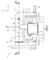
- the printing machine 1 represented on the figure 1 , comprises four printing units 3, 4, 5 and 6 according to the invention, mounted parallel to each other on a carriage 7 slidably mounted on two rails 8 secured to the frame of the printing machine.
- the printing units are directed towards a conveyor 9 where the object to be printed will be placed.
- the carriage 7 and the conveyor 9 are movable perpendicular to each other in a plane perpendicular to the printing direction of the units 3 to 6.
- the carriage 7 and the conveyor 9 are driven by stepper motors as known. in itself.
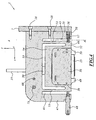
- Each printing unit such as unit 3 represented on the figures 2 and 3 essentially comprises a support plate 11 and an inkjet printing head mounted on the plate.
- the plate 11 is a machined monobloc plate of rectangular shape, comprising two main faces forming a front face 16 and a rear face 17, parallel to the plane defined by X and Y directions.
- the thickness of the plate defines the Z direction.
- the support plate 11 includes a bracket 25 for securing the plate 11 to the carriage 7 by screws 28 visible on the figure 4 .
- the head 15 of rectangular shape is positioned in a notch 39 on the front face 16 of the plate 11, the opening of the head being directed towards the slide.
- the head 15 is fixed to the plate 11, rear side 17, by fixing screws screwed through a fixing plate 36, visible on the figures 1 and 4 .
- the head 15 comprises two pins 37 for positioning the head in the notch 39.
- the head 15 is fed by an ink pipe and electrical cables 19 fixed to the head by a connector 20.
- the plate 11 comprises two lateral slots 41 and 43 and an inner slot 45.
- the two lateral slots 41 and 43 are rectilinear and parallel, in the direction Y.
- the slots 41 and 43 are each open at one end on a side 46 of the platinum, and define two parallel arms forming, at one end, an adjusting arm 47 and, at the other end, the fixing bracket 25.
- Each arm comprises a first end integrally connected to the rest of the plate and a second free end .
- the fixing bracket 25 defines the side of the plate 11 by which the plate is connected to the carriage 7.
- the adjustment arm 47 supports a micrometer adjustment screw 48 with knurled control knob, mounted through the adjustment arm 47 at its free end.
- the micrometer screw 48 presses the plate 11 through the slot 41.
- the side 46 of the plate 11 has two notches 49 and 50, projecting on either side of the notch 39, spaced from the width of the head 15, the head being slightly set back relative to the two notches.
- the inner slot 45 has a U-shape, each of the legs running parallel to each of the two lateral slots 41 and 43.
- the two lateral slots 41 and 43 and the U-shaped slot 45 delimit in the plate 11, beyond the console.
- the two beams 51 and 52 are connected by two branches 53.
- the assembly constituted by the two beams and the two branches forms a parallelogram 54.
- the supporting beam 51 is extended at one end by the adjustment arm 47 and is connected at its other end to the console 25.
- junction zone between the end of the bracket 25 and the supporting beam 51 is weakened by two grooves 55A and 55B on each side of the plate, in the extension of the lateral slot 43 to form an axle hinge extending in the plane of the plate 11 perpendicular to the supporting beam 51.
- the width e of the branches 53 is smaller than the width E of the arm 47 and the console 25.
- the console 25 comprises a transverse hole 56, visible on the figure 4 , in the vicinity of its free end in the direction X.
- This hole 56 contains a spring 57 supported, at one end, on a plug 58 integral with the bracket 25, its other end being pressed against the parallelogram 54 in the extension of the support beam 52 along the axis thereof.
- the turns of the spring 57 are compressed in the X direction between the bracket 25 and the parallelogram 54.
- the spring is able to push the beam 52 of the head support towards the adjustment arm 47 against the action of the screw micrometric 48.
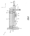
- the console 25 integrates, besides a part of the plate 11, a rigid rigid adjustment beam 61 according to its thickness, arranged along the plate 11, this beam 61 being rigidly connected to the console through the carriage 7.
- the adjustment beam 61 shown on the figures 5 and 6 is secured to the carriage 7. It is fixed to the carriage by fixing screws 63.
- the adjusting beam 61 supports a screw 64 for centering threaded end engaged in a stepped hole 67 of the beam.
- the centering screw 64 is screwed into the plate 11, its head being slidable in the stepped hole 67.
- a compressed spring 73 is interposed between the shoulder 71 and the head of the screw 64.
- the spring tends to bring the plate 11 of the beam 61 by action on the screw 64 connected to the plate.
- the screw 64 is preferably connected to the plate away from the console 25.
- a second micrometer screw 75 with knurled knob is interposed between the plate 11 and the adjusting beam 61.
- the micrometer screw 75 is in a direction Z perpendicular to that of the micrometer screw 48.
- the screw 75 is applied away from the bracket 25 in the vicinity of the spring 73.
- the positioning of the printing unit 3 relative to the carriage, and therefore to the other printing units, is done by means of two micrometric screws 48 and 75.
- micrometric screw 48 driven manually in rotation presses in the X direction against the support beam 52, which is urged in the opposite direction by the compressed spring 57.
- the beam 52 is biased along its axis from one end by the spring 57 and from its other end by the micrometer screw 48.
- the spring and the screw both act to push the beam 52.
- the width E of the adjustment arm 47 and the bracket 25 being greater than the width e of the branches 53, the beam 52 is displaced relative to the adjustment arm 47 by deformation of the parallelogram 54, the branches 53 deforming and articulating in particular at the ends of the indeformable beams 51 and 52.
- the parallelogram 54 is assumed to be a rectangle, the beams 51 and 52 being parallel, as the branches 53 .
- the user acts on the screw 48 to compress the spring 57.
- the user looses the micrometer screw 48, so that the beam 52 is moved under the action of the spring 57.
- the combined action of the spring 57 and the micrometer screw 48 allows a displacement of the beam 52 and thus the head 15 on either side of the equilibrium position of the parallelogram 54.
- the supporting beam 51 is angularly displaced with respect to the console 25 under the counteracting actions of the micrometer screw 75 and springs 73.
- the supporting beam 51 is assumed parallel to the beam 61.
- the micrometer screw 75 is tightened, leading to an accentuated compression of the spring 73.
- the screw 75 is loosened and the spring 73 still compressed recalls the end of the beam 51.
- the displacement of the beam 51 is done by articulation around the hinge delimited by the two grooves 55A, 55B.
- the action on the micrometric screw 48 combined with the spring 57 ensures an exactly identical positioning of the heads 15 in the direction X perpendicular to the carriage.
- the platen 11 being integrally formed, and the latter being elastically deformable, the support of the head 15 is relatively simple to manufacture and inexpensive while allowing a reliable and accurate positioning of each print head.
- the springs 57, 73 and the micrometer screws 48, 75 forming actuators are capable of ensuring movements of the head of +/- 0.4 mm, ie the spacing between two nozzles of printing heads in which the nozzles are spaced apart. 0.32 mm (80 dpi).
- the two unhooks 49 and 50 of the support part between which the head 15 is positioned slightly set back, allow the head 15 never come into contact with the object to be printed, even in case of mishandling during adjustment.
- the head 15, fragile and expensive part, is thus protected.
Landscapes
- Engineering & Computer Science (AREA)
- Quality & Reliability (AREA)
- Ink Jet (AREA)
Claims (14)
- Druckeinheit (3) einer Tintenstrahldruckmaschine der Art, die umfasst:- einen Tintenstrahlkopf (15);- eine Halteplatte (11) für den Kopf, wobei die Halteplatte (11) eine Konsole (25) zur Befestigung der Halteplatte (11) für den Kopf (15) an einer Druckmaschine (1) aufweist; und- Einstellungsmittel (48, 57, 73, 75) zur Ausrichtung des Kopfes (15) hinsichtlich der Befestigungskonsole (25), die ein erstes Justierglied (48, 57) umfassen, das auf der Halteplatte (11) angewandt ist, wobei die Halteplatte (11) nach mindestens einer Richtung (X, Z) unter Einwirkung des ersten Justierglieds (48, 57) elastisch verformbar ist,dadurch gekennzeichnet, dass die Befestigungskonsole (25) einen starren Justierträger (61) aufweist, wobei die Einheit ein zweites Justierglied (73, 75) aufweist, das zwischen der Halteplatte (11) und dem starren Justierträger (61) zwischengelegt ist und sich in einer Richtung senkrecht zu derjenigen des auf die Halteplatte (11) angewandten ersten Justierglieds (48) erstreckt.
- Druckeinheit (3) nach Anspruch 1, dadurch gekennzeichnet, dass die Halteplatte (11) aus einem Stück ist.
- Druckeinheit (3) nach Anspruch 2, dadurch gekennzeichnet, dass die Halteplatte (11) ein bearbeitetes massives Teil ist.
- Druckeinheit (3) nach einem der vorhergehenden Ansprüche, dadurch gekennzeichnet, dass die Halteplatte (11) ein verformbares Vierseit (54) bestimmt, wobei eine Seite desselben einen starren Stützträger (51) bildet, wobei ein Stellglied (48) sich parallel zum starren Stützträger (51) an einem Punkt des Vierseits (54) anfügt, der vom starren Stützträger (51) beabstandet ist.
- Druckeinheit (3) nach Anspruch 4, dadurch gekennzeichnet, dass die Halteplatte (11) außer dem Stützträger (51) einen starren Kopfträger (52) und zwei Schenkel (53), welche den Stützträger und den Kopfträger (51, 52) miteinander verbinden, umfasst, wobei der Kopf (15) fest mit dem Kopfträger (52) verbunden ist, wobei das Justierglied (48, 57) auf den Kopfträger (52) angewandt ist.
- Druckeinheit (3) nach Anspruch 5, dadurch gekennzeichnet, dass die Halteplatte (11) einen Einstellarm (47) bestimmt, der mit dem Stützträger (51) fest verbunden ist, und die Biegefestigkeit jedes Schenkels (53) kleiner als die Biegefestigkeit des Einstellungsarms (47) ist, wobei das Justierglied (48, 57) zwischen dem Einstellungsarm (47) und dem Kopfträger (52) zwischengelegt ist.
- Druckeinheit (3) nach Anspruch 5 oder 6, dadurch gekennzeichnet, dass das Justierglied einen Stößel (48) aufweist, der auf den Träger (52) einwirkt.
- Druckeinheit (3) nach Anspruch 7, dadurch gekennzeichnet, dass das Justierglied eine Feder (57) zur Belastung des Kopfträgers (52) zum Stößel (48) hin aufweist.
- Druckeinheit (3) nach einem der Ansprüche 1 bis 8, dadurch gekennzeichnet, dass die Halteplatte (11) einen starren Stützträger (51) aufweist und im Winkel auf elastische Weise in Bezug auf den Träger (61) verformbar ist.
- Druckeinheit (3) nach Anspruch 9, dadurch gekennzeichnet, dass die Halteplatte (11) einen Abschnitt aufweist, der zwischen dem starren Träger (11) und der Befestigungskonsole (25) ein Gelenk (55A, 55B) bildet.
- Druckeinheit (3) nach Anspruch 10, dadurch gekennzeichnet, dass die Halteplatte (11) mindestens eine geradlinige Schwächungsnut (55A, 55B) senkrecht zum Träger (61) aufweist, die das Gelenk zwischen dem starren Einstellungsträger (51) und der Befestigungskonsole (25) bildet.
- Druckeinheit (3) nach einem der Ansprüche 9, 10 und 11, dadurch gekennzeichnet, dass das Justierglied einen Stößel (75) aufweist, der zwischen dem Träger (51) und dem Justierträger (61) wirkt.
- Druckeinheit (3) nach Anspruch 12, dadurch gekennzeichnet, dass das Justierglied eine Feder zur Belastung des Stützträgers (51) zum Stößel (75) hin aufweist.
- Tintenstrahldruckmaschine (1), dadurch gekennzeichnet, dass sie mindestens eine Druckeinheit (3) nach einem der vorhergehenden Ansprüche aufweist.
Priority Applications (1)
| Application Number | Priority Date | Filing Date | Title |
|---|---|---|---|
| PL07290595T PL1854635T3 (pl) | 2006-05-11 | 2007-05-10 | Zespół drukujący z odkształcalną podporą |
Applications Claiming Priority (1)
| Application Number | Priority Date | Filing Date | Title |
|---|---|---|---|
| FR0604204A FR2900867B1 (fr) | 2006-05-11 | 2006-05-11 | Unite d'impression a support deformable |
Publications (2)
| Publication Number | Publication Date |
|---|---|
| EP1854635A1 EP1854635A1 (de) | 2007-11-14 |
| EP1854635B1 true EP1854635B1 (de) | 2008-12-17 |
Family
ID=37672188
Family Applications (1)
| Application Number | Title | Priority Date | Filing Date |
|---|---|---|---|
| EP07290595A Not-in-force EP1854635B1 (de) | 2006-05-11 | 2007-05-10 | Druckereinheit mit verformbarer Halterung |
Country Status (5)
| Country | Link |
|---|---|
| EP (1) | EP1854635B1 (de) |
| DE (1) | DE602007000370D1 (de) |
| ES (1) | ES2318836T3 (de) |
| FR (1) | FR2900867B1 (de) |
| PL (1) | PL1854635T3 (de) |
Families Citing this family (4)
| Publication number | Priority date | Publication date | Assignee | Title |
|---|---|---|---|---|
| EP2287006B1 (de) * | 2006-12-22 | 2012-11-21 | Fujifilm Dimatix, Inc. | Einstellbare Montagedruckkopfanordnung |
| CN102490471B (zh) * | 2011-11-25 | 2014-11-05 | 深圳市润天智数字设备股份有限公司 | 一种喷头定位装置及应用该装置的喷绘打印机 |
| GB2549487B (en) | 2016-04-18 | 2020-01-01 | Xaar Technology Ltd | Droplet deposition head alignment system |
| US10632773B2 (en) | 2017-04-25 | 2020-04-28 | Heidelberger Druckmaschinen Ag | Mounting device for a print head, a mounting assembly and a printing system |
Family Cites Families (1)
| Publication number | Priority date | Publication date | Assignee | Title |
|---|---|---|---|---|
| DE69412805T2 (de) * | 1994-07-18 | 1999-03-11 | Oce-Nederland B.V., Venlo | Drucker mit einem beweglichen Druckkopf |
-
2006
- 2006-05-11 FR FR0604204A patent/FR2900867B1/fr not_active Expired - Fee Related
-
2007
- 2007-05-10 EP EP07290595A patent/EP1854635B1/de not_active Not-in-force
- 2007-05-10 DE DE602007000370T patent/DE602007000370D1/de active Active
- 2007-05-10 ES ES07290595T patent/ES2318836T3/es active Active
- 2007-05-10 PL PL07290595T patent/PL1854635T3/pl unknown
Also Published As
| Publication number | Publication date |
|---|---|
| FR2900867B1 (fr) | 2010-06-04 |
| PL1854635T3 (pl) | 2009-06-30 |
| DE602007000370D1 (de) | 2009-01-29 |
| ES2318836T3 (es) | 2009-05-01 |
| EP1854635A1 (de) | 2007-11-14 |
| FR2900867A1 (fr) | 2007-11-16 |
Similar Documents
| Publication | Publication Date | Title |
|---|---|---|
| EP1854635B1 (de) | Druckereinheit mit verformbarer Halterung | |
| FR2733456A1 (fr) | Ensemble d'arbre de guidage pour une imprimante | |
| FR2935925A1 (fr) | Support de racle et outil de desserrage de ce support de racle. | |
| EP0855272B1 (de) | Druckkopf für Poststücke mit Ausrichtvorrichtung | |
| EP1396293B1 (de) | Befestigungssystem eines Biegewerkzeuges | |
| EP1364600B1 (de) | Steifheitseinstellungssystem für Kugelgelenk in einem Bettrost | |
| EP0972639B1 (de) | Vorrichtung zum Einstellen einer flexiblen Druckplatte auf einem Formzylinder | |
| EP0023269B1 (de) | Druckwerk mit einem herausnehmbaren Matrixdruckkopf | |
| EP2648877B1 (de) | Klemm-/löseflansch | |
| FR2952898A1 (fr) | Gabarit de positionnement pour la fixation d'une piece d'equipement sur un element de carrosserie d'un vehicule | |
| FR2505694A1 (fr) | Dispositif permettant le reglage de la forme du tranchant de la lame superieure de cisailles a balancier comportant une lame pivotante, dans le cas d'une fixation rigide de la lame | |
| FR2642004A1 (fr) | Imprimante thermique grande largeur | |
| EP0453533B1 (de) | Numerisch gesteuerte maschine zum bearbeiten oder messen mit einer befestigungsvorrichtung für ein werkstück auf einem werktisch | |
| EP1112154B1 (de) | Vorrichtung zur verstellung einer platte auf einem zylinder mit magnetischen befestigungselementen | |
| EP1400356B1 (de) | Anordnung mit einem Gummituch und einem Gummituchzylinder; Zylinder, Gummituch und Druckmaschine | |
| FR2569835A1 (fr) | Tete pour la mesure de diametres de pieces cylindriques | |
| FR2776566A1 (fr) | Cylindre de groupe d'impression equipe d'une plaque d'impression a extremites coudees, se fixant sur lui, pour machines rotatives a imprimer | |
| EP0023270B1 (de) | Punktdrucker mit einem schwenkbaren Druckkopf | |
| EP0916488A1 (de) | Automatisches Siebdrucksystem | |
| EP0037754B1 (de) | Vorrichtung zum Korrigieren des Standes einer durch einen Zylinder einer Druckmaschine getragenen Druckplatte | |
| EP3387495B1 (de) | Rattrapante-mechanismus | |
| FR2749794A1 (fr) | Dispositif de clivage d'une plaque de materiau semi-conducteur | |
| EP1369606A1 (de) | Markierungsapparat mit mindestens einer Führungsvorrichtung und mindestens einer Antriebslaufkatze | |
| FR3092131A1 (fr) | Dispositif de maintien configuré pour maintenir une échelle contre une surface | |
| FR2547370A1 (fr) | Dispositif de fixation |
Legal Events
| Date | Code | Title | Description |
|---|---|---|---|
| PUAI | Public reference made under article 153(3) epc to a published international application that has entered the european phase |
Free format text: ORIGINAL CODE: 0009012 |
|
| AK | Designated contracting states |
Kind code of ref document: A1 Designated state(s): AT BE BG CH CY CZ DE DK EE ES FI FR GB GR HU IE IS IT LI LT LU LV MC MT NL PL PT RO SE SI SK TR |
|
| AX | Request for extension of the european patent |
Extension state: AL BA HR MK YU |
|
| 17P | Request for examination filed |
Effective date: 20080507 |
|
| AKX | Designation fees paid |
Designated state(s): DE ES GB PL |
|
| GRAP | Despatch of communication of intention to grant a patent |
Free format text: ORIGINAL CODE: EPIDOSNIGR1 |
|
| GRAS | Grant fee paid |
Free format text: ORIGINAL CODE: EPIDOSNIGR3 |
|
| GRAA | (expected) grant |
Free format text: ORIGINAL CODE: 0009210 |
|
| AK | Designated contracting states |
Kind code of ref document: B1 Designated state(s): DE ES GB PL |
|
| REG | Reference to a national code |
Ref country code: GB Ref legal event code: FG4D Free format text: NOT ENGLISH |
|
| REF | Corresponds to: |
Ref document number: 602007000370 Country of ref document: DE Date of ref document: 20090129 Kind code of ref document: P |
|
| REG | Reference to a national code |
Ref country code: ES Ref legal event code: FG2A Ref document number: 2318836 Country of ref document: ES Kind code of ref document: T3 |
|
| REG | Reference to a national code |
Ref country code: PL Ref legal event code: T3 |
|
| PLBE | No opposition filed within time limit |
Free format text: ORIGINAL CODE: 0009261 |
|
| STAA | Information on the status of an ep patent application or granted ep patent |
Free format text: STATUS: NO OPPOSITION FILED WITHIN TIME LIMIT |
|
| 26N | No opposition filed |
Effective date: 20090918 |
|
| PGFP | Annual fee paid to national office [announced via postgrant information from national office to epo] |
Ref country code: PL Payment date: 20150508 Year of fee payment: 9 |
|
| PGFP | Annual fee paid to national office [announced via postgrant information from national office to epo] |
Ref country code: MC Payment date: 20170720 Year of fee payment: 13 |
|
| PG25 | Lapsed in a contracting state [announced via postgrant information from national office to epo] |
Ref country code: PL Free format text: LAPSE BECAUSE OF NON-PAYMENT OF DUE FEES Effective date: 20160510 |
|
| PGFP | Annual fee paid to national office [announced via postgrant information from national office to epo] |
Ref country code: GB Payment date: 20180613 Year of fee payment: 12 Ref country code: ES Payment date: 20180725 Year of fee payment: 12 |
|
| REG | Reference to a national code |
Ref country code: DE Ref legal event code: R119 Ref document number: 602007000370 Country of ref document: DE |
|
| PG25 | Lapsed in a contracting state [announced via postgrant information from national office to epo] |
Ref country code: DE Free format text: LAPSE BECAUSE OF NON-PAYMENT OF DUE FEES Effective date: 20181201 |
|
| GBPC | Gb: european patent ceased through non-payment of renewal fee |
Effective date: 20190510 |
|
| PG25 | Lapsed in a contracting state [announced via postgrant information from national office to epo] |
Ref country code: GB Free format text: LAPSE BECAUSE OF NON-PAYMENT OF DUE FEES Effective date: 20190510 |
|
| REG | Reference to a national code |
Ref country code: ES Ref legal event code: FD2A Effective date: 20200925 |
|
| PG25 | Lapsed in a contracting state [announced via postgrant information from national office to epo] |
Ref country code: ES Free format text: LAPSE BECAUSE OF NON-PAYMENT OF DUE FEES Effective date: 20190511 |