EP1854111B1 - Winding method and coil unit - Google Patents
Winding method and coil unit Download PDFInfo
- Publication number
- EP1854111B1 EP1854111B1 EP06832481A EP06832481A EP1854111B1 EP 1854111 B1 EP1854111 B1 EP 1854111B1 EP 06832481 A EP06832481 A EP 06832481A EP 06832481 A EP06832481 A EP 06832481A EP 1854111 B1 EP1854111 B1 EP 1854111B1
- Authority
- EP
- European Patent Office
- Prior art keywords
- wires
- winding
- coil
- bobbin
- lane change
- Prior art date
- Legal status (The legal status is an assumption and is not a legal conclusion. Google has not performed a legal analysis and makes no representation as to the accuracy of the status listed.)
- Not-in-force
Links
- 238000004804 winding Methods 0.000 title claims description 98
- 238000000034 method Methods 0.000 title claims description 53
- 238000004519 manufacturing process Methods 0.000 claims description 6
- 238000010586 diagram Methods 0.000 description 12
- 230000000694 effects Effects 0.000 description 3
- 239000004734 Polyphenylene sulfide Substances 0.000 description 2
- 229920000069 polyphenylene sulfide Polymers 0.000 description 2
- RYGMFSIKBFXOCR-UHFFFAOYSA-N Copper Chemical compound [Cu] RYGMFSIKBFXOCR-UHFFFAOYSA-N 0.000 description 1
- 210000003298 dental enamel Anatomy 0.000 description 1
- 238000009413 insulation Methods 0.000 description 1
- 229920003002 synthetic resin Polymers 0.000 description 1
- 239000000057 synthetic resin Substances 0.000 description 1
Images







Classifications
-
- H—ELECTRICITY
- H01—ELECTRIC ELEMENTS
- H01F—MAGNETS; INDUCTANCES; TRANSFORMERS; SELECTION OF MATERIALS FOR THEIR MAGNETIC PROPERTIES
- H01F5/00—Coils
- H01F5/02—Coils wound on non-magnetic supports, e.g. formers
-
- H—ELECTRICITY
- H01—ELECTRIC ELEMENTS
- H01F—MAGNETS; INDUCTANCES; TRANSFORMERS; SELECTION OF MATERIALS FOR THEIR MAGNETIC PROPERTIES
- H01F41/00—Apparatus or processes specially adapted for manufacturing or assembling magnets, inductances or transformers; Apparatus or processes specially adapted for manufacturing materials characterised by their magnetic properties
- H01F41/02—Apparatus or processes specially adapted for manufacturing or assembling magnets, inductances or transformers; Apparatus or processes specially adapted for manufacturing materials characterised by their magnetic properties for manufacturing cores, coils, or magnets
- H01F41/04—Apparatus or processes specially adapted for manufacturing or assembling magnets, inductances or transformers; Apparatus or processes specially adapted for manufacturing materials characterised by their magnetic properties for manufacturing cores, coils, or magnets for manufacturing coils
- H01F41/06—Coil winding
- H01F41/064—Winding non-flat conductive wires, e.g. rods, cables or cords
-
- H—ELECTRICITY
- H01—ELECTRIC ELEMENTS
- H01F—MAGNETS; INDUCTANCES; TRANSFORMERS; SELECTION OF MATERIALS FOR THEIR MAGNETIC PROPERTIES
- H01F41/00—Apparatus or processes specially adapted for manufacturing or assembling magnets, inductances or transformers; Apparatus or processes specially adapted for manufacturing materials characterised by their magnetic properties
- H01F41/02—Apparatus or processes specially adapted for manufacturing or assembling magnets, inductances or transformers; Apparatus or processes specially adapted for manufacturing materials characterised by their magnetic properties for manufacturing cores, coils, or magnets
- H01F41/04—Apparatus or processes specially adapted for manufacturing or assembling magnets, inductances or transformers; Apparatus or processes specially adapted for manufacturing materials characterised by their magnetic properties for manufacturing cores, coils, or magnets for manufacturing coils
- H01F41/06—Coil winding
- H01F41/064—Winding non-flat conductive wires, e.g. rods, cables or cords
- H01F41/069—Winding two or more wires, e.g. bifilar winding
-
- H—ELECTRICITY
- H01—ELECTRIC ELEMENTS
- H01F—MAGNETS; INDUCTANCES; TRANSFORMERS; SELECTION OF MATERIALS FOR THEIR MAGNETIC PROPERTIES
- H01F41/00—Apparatus or processes specially adapted for manufacturing or assembling magnets, inductances or transformers; Apparatus or processes specially adapted for manufacturing materials characterised by their magnetic properties
- H01F41/02—Apparatus or processes specially adapted for manufacturing or assembling magnets, inductances or transformers; Apparatus or processes specially adapted for manufacturing materials characterised by their magnetic properties for manufacturing cores, coils, or magnets
- H01F41/04—Apparatus or processes specially adapted for manufacturing or assembling magnets, inductances or transformers; Apparatus or processes specially adapted for manufacturing materials characterised by their magnetic properties for manufacturing cores, coils, or magnets for manufacturing coils
- H01F41/06—Coil winding
- H01F41/082—Devices for guiding or positioning the winding material on the former
-
- H—ELECTRICITY
- H01—ELECTRIC ELEMENTS
- H01F—MAGNETS; INDUCTANCES; TRANSFORMERS; SELECTION OF MATERIALS FOR THEIR MAGNETIC PROPERTIES
- H01F41/00—Apparatus or processes specially adapted for manufacturing or assembling magnets, inductances or transformers; Apparatus or processes specially adapted for manufacturing materials characterised by their magnetic properties
- H01F41/02—Apparatus or processes specially adapted for manufacturing or assembling magnets, inductances or transformers; Apparatus or processes specially adapted for manufacturing materials characterised by their magnetic properties for manufacturing cores, coils, or magnets
- H01F41/04—Apparatus or processes specially adapted for manufacturing or assembling magnets, inductances or transformers; Apparatus or processes specially adapted for manufacturing materials characterised by their magnetic properties for manufacturing cores, coils, or magnets for manufacturing coils
- H01F41/06—Coil winding
- H01F41/098—Mandrels; Formers
-
- H—ELECTRICITY
- H01—ELECTRIC ELEMENTS
- H01F—MAGNETS; INDUCTANCES; TRANSFORMERS; SELECTION OF MATERIALS FOR THEIR MAGNETIC PROPERTIES
- H01F5/00—Coils
- H01F5/04—Arrangements of electric connections to coils, e.g. leads
-
- H—ELECTRICITY
- H02—GENERATION; CONVERSION OR DISTRIBUTION OF ELECTRIC POWER
- H02K—DYNAMO-ELECTRIC MACHINES
- H02K15/00—Processes or apparatus specially adapted for manufacturing, assembling, maintaining or repairing of dynamo-electric machines
- H02K15/04—Processes or apparatus specially adapted for manufacturing, assembling, maintaining or repairing of dynamo-electric machines of windings prior to their mounting into the machines
- H02K15/043—Processes or apparatus specially adapted for manufacturing, assembling, maintaining or repairing of dynamo-electric machines of windings prior to their mounting into the machines winding flat conductive wires or sheets
- H02K15/0431—Concentrated windings
-
- H—ELECTRICITY
- H02—GENERATION; CONVERSION OR DISTRIBUTION OF ELECTRIC POWER
- H02K—DYNAMO-ELECTRIC MACHINES
- H02K3/00—Details of windings
- H02K3/04—Windings characterised by the conductor shape, form or construction, e.g. with bar conductors
- H02K3/18—Windings for salient poles
-
- H—ELECTRICITY
- H02—GENERATION; CONVERSION OR DISTRIBUTION OF ELECTRIC POWER
- H02K—DYNAMO-ELECTRIC MACHINES
- H02K3/00—Details of windings
- H02K3/46—Fastening of windings on the stator or rotor structure
- H02K3/52—Fastening salient pole windings or connections thereto
- H02K3/521—Fastening salient pole windings or connections thereto applicable to stators only
- H02K3/522—Fastening salient pole windings or connections thereto applicable to stators only for generally annular cores with salient poles
Definitions
- the present invention relates to a winding method of regularly winding wires on a bobbin, and a coil unit manufactured by the method.
- This type of technique has been know as a winding method disclosed in each of Japanese unexamined patent publications Nos. 2000-245092 , 8(1996)-203720 , and 2000-348959 .
- the publication 092 discloses a winding method for concentrated winding, intended to prevent enlargement of coil size and achieve a reduction in coil size, by providing a layer shift part and a row shift part of a coil in separate positions on the periphery of the coil.
- the publication '720 discloses a method of regularly winding a wire in multilayered form on a bobbin while feeding the wire at 1/2 pitch of a wire diameter on two opposite surfaces of a rectangular coil.
- the winding methods disclosed in the publications '092 and '720 are however the winding methods of winding a single wire on a bobbin and not particularly directed to winding of a plurality of wires.
- a raised portion of the wound wires is likely to be generated near an end of the bobbin. This would result from inclination and floating of the wire at a row shift part and a layer shift part in the regularly winding, namely, in the winding turn-back position.
- the regularly concentrated winding coil is likely to disorder the arrangement of the wires in the turn back portions, which is one of factors causing enlargement of a coil outer size, leading to obstruction of miniaturization of the concentrated winding coil.
- the present invention has been made in view of the above circumstances and has an object to provide a method of regularly winding four wires, capable of preventing the occurrence of a raised portion of the wires in the winding turn-back position, thereby achieving a compact coil, and a coil manufactured by the winding method.
- the present invention provides a winding method of regularly winding four wires on a bobbin that is rectangular in section, having four outer surfaces including a pair of parallel surfaces, the method comprising the step of: winding the wires on the bobbin so that the wires advance obliquely together for a lane change corresponding to 0.5 wire on one of the pair of parallel surfaces and for a lane change corresponding to 3.5 wires on the other one of the pair of parallel surfaces.
- the wires are wound in such a manner as to advance obliquely together for the lane change corresponding to 0.5 wire (i.e. a half wire diameter) on one surface side of the pair of parallel surfaces of the four outer surfaces of the bobbin and the lane change corresponding to 3.5 wires (i.e. three and a half wire diameters) on the other surface side of the parallel surfaces.
- This method can provide less inclination of the wires as compared with for instance the lane change corresponding to 4 wires on one of the outer surfaces of the bobbin, with a consequent result that intersection of layered wires in the winding turn-back position can be reduced.
- the present invention does not cause two of the four wires to be left uncoiled in the turn-back position where the winding is completed.
- the present invention can reduce intersection of the layered wires in the winding turn-back position, thus preventing the wires from remaining uncoiled in the winding end position.
- the winding method is used to manufacture a rectangular coil unit including a coil having a rectangular section.
- the winding method is used to manufactured 3a trapezoidal coil unit including a coil having a trapezoidal section.
- the present invention provides a coil unit including four wires regularly wound on a bobbin that is rectangular in section and has four outer surfaces including a pair of parallel surfaces, wherein the wires are wound on the bobbin so that the wires advance obliquely together for a lane change corresponding to 0.5 wire on one of the pair of parallel surfaces and a lane change corresponding to 3.5 wires on the other one of the pair of parallel surfaces.
- the wires are wound to advance obliquely together for the lane change corresponding to 0.5 wire (i.e. a half wire diameter) on one surface side of the pair of parallel surfaces of the four outer surfaces of the bobbin and the lane change corresponding to 3.5 wires (i.e. three and a half wire diameters) on the other surface side of the parallel surfaces.
- the coil of the present invention can include less inclination of the wires as compared with for instance the lane change corresponding to 4 wires on one of the outer surfaces of the bobbin, with a consequent result that intersection of layered wires in turn-back positions of winding can be reduced.
- the present invention does not cause two of the four wires to be left uncoiled in the turn-back position where the winding is completed.
- the present invention can reduce intersection of the layered wires in the winding turn-back positions, thus preventing the wires from remaining uncoiled in the winding end position.
- Fig. 1 is a perspective view of a rectangular coil unit 1 in the present embodiment.
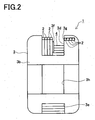
- Fig. 2 is a back view of the rectangular coil unit 1.
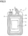
- Fig. 3 is a front view of the rectangular coil unit 1 from which a first flange is removed for convenience of explanation.
- the rectangular coil unit 1 in the present embodiment is manufactured in such a manner that four wires 2 are simultaneously regularly wound on four outer surfaces of a bobbin 3 having a rectangular section.
- a plurality of the rectangular coil units 1 will be mounted in a plurality of teeth formed on the inner periphery of a stator core, thus constituting a stator.
- This stator is further assembled with a rotor, producing a motor.
- the bobbin 3 includes a core tube 3a of a rectangular section, a first flange 3b and a second flange 3c formed at both axial ends of the core tube 3a.
- the bobbin 3 is made of a synthetic resin such as PPS (polyphenylene sulfide) to have an insulating property.
- the first flange 3b provided on a rear side has a distinctive shape as compared with the second flange 3c provided on a front side having a nearly normal rectangular shape.
- the first flange 3b includes upper and lower cutout portions 3d and 3e, an insulating wall 3f protruding from one of side surfaces of the upper cutout portion 3d in Fig.
- the core tube 3a is hollow, providing a center hole 3h. A clearance is formed between the insulating wall 3f and a lower surface of the upper cutout portion 3d as shown in Fig. 2 .
- Onto the core tube 3a four wires 2 are simultaneously regularly wound, forming a coil 4 having a hollow rectangular shape. Both end portions of each of four wires 2 are partly engaged with the insulating wall 3f and the stopper groove 3g.
- a relatively thick wire 2 is used to achieve a small-sized high-power motor.
- the wire 2 is made of a copper wire coated with an enamel insulating film.
- the four wires 2 are wound regularly and reciprocally in opposite directions along the axis of the core tube 3a as above, forming the coil 4 with a plurality of rows and a plurality of layers of wires 2. After winding, the end portions of the two wires 2 are engaged in the stopper groove 3g.
- the rectangular coil unit 1 including the coil 4 formed in the above manner to have a rectangular section is thus manufactured.
- the wiring method in the present embodiment has special features in a method of winding four wires 2.
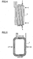
- Fig. 4 is a side view of the coil 4 on the bobbin 3.
- Fig. 5 is a back view of the coil 4 on the bobbin 3.
- Figs. 6A to 6D are views seen from directions indicated by arrows A, B, C, and D in Fig. 4 .
- Fig. 7 is a pattern diagram of the arrangement of the coil 4 on the bobbin 3.
- the wires 2 are wound in such a manner as to advance obliquely together for a lane change corresponding to 0.5 wire (i.e.
- a half wire diameter) on a lower surface side of the core tube 3a of the bobbin 3 having four outer surfaces including a pair of upper and lower parallel surfaces and to advance obliquely together for a lane change corresponding to 3.5 wires (i.e. three and a half wire diameters) on an upper surface side thereof (hereinafter, this winding method is referred to as "3.5-0.5 change").
- this winding method is referred to as "3.5-0.5 change"
- wires 2 start to be wound from an upper side and along the first flange 3b to a left side, and then vertically downward to a lower side. Successively, the wires 2 advance obliquely together for the 0.5-wire lane change on the lower side, as indicated by number “1” in Fig. 6B , and then vertically upward on a right side to the upper side. As indicated by numbers “1” and “2" in Fig. 6A , on the upper side, the wires 2 advance obliquely together for the 3.5 wire lane change and vertically downward again on the left side to the lower side.
- the above lane changes are repeated as in the above manner on the upper side and the lower side respectively.
- the first layer of the coil 4 is thus formed (the first layer has 3 turns as indicated by numbers “1" to "3" in Figs. 6A and 6B .)
- the wires 2 are turned (folded) back at an opposite position from the winding start position.
- the 0.5-wire lane change is performed in the direction opposite to that for the first layer as shown in Fig. 6B .
- the 3.5-wire lane change is performed conducted in the direction opposite to that the first layer as shown in Fig. 6A .
- Figs. 8A to 8D are views seen from the directions indicated by arrows A, B, C, and D in Fig. 4 .
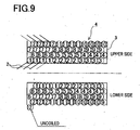
- Fig. 9 is a pattern- diagram showing an arrangement of the coil 4 on the bobbin 3.
- four wires 2 are wound in such a manner as to advance obliquely together for a lane change corresponding to 1 wire (i.e. one wire diameter) on the lower surface side of the core tube 3a of the bobbin 3 having four outer surfaces including a pair of upper and lower surface and for a lane change corresponding to 3 wires (i.e.
- this winding method is referred to as "3-1 change").
- the lane changes corresponding to a total of four wire diameters are performed on the upper and lower sides of the bobbin 3.
- This winding method causes the wires 2 to intersect and overlap in the winding turn-back position, generating a raised portion as shown by a dot-dashed circular line S1 in Fig. 8D .
- Fig. 9 an empty space is created in a winding start position of the coil 4.
- one of the four wires 2 is left uncoiled in that winding end position.
- Figs. 10A to 10D are views seen from the directions indicated by arrows A, B, C, and D in Fig. 4 .
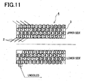
- Fig. 11 is a pattern diagram of the arrangement of the coil 4 on the bobbin 3.
- the wires 2 are wound in such a manner as to advance obliquely together for a lane change corresponding to 1.5 wire (i.e. one and a half wire diameters) on a lower surface side of the core tube 3a of the bobbin 3 having four outer surfaces including a pair of upper and lower surface and to advance obliquely together for as lane change corresponding to 2.5 wires (i.e.
- this winding method is referred to as "2.5-1.5 change").
- This winding method causes the wires 2 to intersect and overlap in three layers in the winding turn-back position as a shaded area shown in Fig. 10B , generating a raised portion as shown by a dot-dashed circular line S1 in Fig. 10D .
- an empty space is created in a winding start position of the coil 4.
- Figs. 12A to 12D are views seen from the directions indicated by arrows A, B, C, and D in Fig. 4 .
- Fig. 13 is a pattern diagram of the arrangement of the coil 4 on the bobbin 3.
- the wires 2 are wound in such a manner as to advance obliquely together for a lane change corresponding to 2 wires (i.e. two wire diameters) on a lower surface side of the core tube 3a of the bobbin 3 having four outer surfaces including a pair of upper and lower surfaces and to advance obliquely together for a lane change corresponding to 2 wires (i.e.
- this winding method is referred to as "2-2 change").
- This winding method causes the wires 2 to intersect and overlap in three layers in the winding turn-back position as a shaded area shown in Fig. 12B , generating a raised portion as shown by a dot-dashed circular line S1 in Fig. 12D .
- an empty space is created in a winding start position of the coil 4.
- Figs. 14A to 14D are views seen from the directions indicated by arrows A, B, C, and D in Fig. 4 .
- Fig. 15 is a pattern diagram of the arrangement of the coil 4 on the bobbin 3.
- the wires 2 are wound in such a manner as to advance obliquely together for a lane change corresponding to 2.5 wires (i.e. two and a half wire diameters) on a lower surface side of the core tube 3a of the bobbin 3 having four outer surfaces including a pair of upper and lower surfaces and to advance obliquely together for a lane change corresponding to 1.5 wires (i.e.
- this winding method is referred to as "1.5-2.5 change").
- This winding method causes the wires 2 to intersect and overlap in three layers in the winding turn-back position as a shaded area shown in Fig. 14B , generating a raised portion as shown by a dot-dashed circular line S1 in Fig. 14D .
- Fig. 15 an empty space is created in a winding start position of the coil 4.
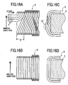
- Figs. 16A to 16D are views seen from the directions indicated by arrows A, B, C, and D in Fig. 4 .
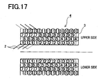
- Fig. 17 is a pattern diagram of the arrangement of the coil 4 on the bobbin 3.
- the wires 2 are wound in such a manner as to traverse straight for a lane change corresponding to 0 wire (i.e. no lane change) on a lower surface side of the core tube 3a of the bobbin 3 having four outer surfaces including a pair of upper and lower surfaces and to advance obliquely together for a lane change corresponding to 4 wires (i.e.
- this winding method is referred to as "4-0 change").
- the lane changes corresponding to a total of four wire diameters are performed on the upper and lower sides of the bobbin 3.
- This winding method causes the wires 2 to be twisted 180° in the winding turn-back position for a layer shift, so that the wires 2 intersect and overlap in three layers as 3a shaded area shown in Fig. 16C , generating a raised portion as shown by a dot-dashed circular line S1 in Figs. 16A .
- the 0.5-wire lane change of the wires 2 is performed on the lower surface side of the core tube 3a of the bobbin 3 having four outer surfaces including a pair or upper and lower surfaces and the 3.5-wire lane change is performed on the upper surface side.
- This winding method in the present embodiment enables less inclination of the wires 2, leading to less intersection of the layered wires 2 of the coil 4 in the vicinity of each flange 3b, 3c of the bobbin 3 at which the winding operation is turned back, as compared with the winding methods shown in Figs.
- the winding method in the present embodiment does not leave one or two of the wires 2 uncoiled in the winding end position located in the vicinity of each flange 3b, 3c of the bobbin 3 where the winding is completed. Accordingly, in simultaneously regularly winding four wires 2 for the rectangular coil unit 1, it is possible to prevent the generation of a raised portion in the winding turn-back position. This makes it possible to form the coil 4 compact without enlarging the outer size of the coil 4.
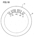
- this rectangular coil unit 1 may be mounted in each of teeth 12a of a stator core 12 in such a manner that trapezoidal coil units 11 and rectangular coil units 1 are alternately arranged to constitute a stator 13.
- the generation of a raised portion in the winding turn-back position can be restrained, thus making compact the coil 4 of the rectangular coil unit 1.
- a predetermined distance can be ensured between the coil 4 of the rectangular coil unit 1 and the coil 4 of the trapezoidal coil unit 11 adjacent thereto. It is therefore possible to increase a space factor in assembly, ensure the insulation between the adjacently arranged coil units 1 and 11, and thus enhance performance of a motor using the above stator 13.
- the rectangular coil unit 1 manufactured according to the winding method in the present embodiment is configured so that four wire 2 are simultaneously, regularly wound on the bobbin 3.
- the eddy-current loss of the rectangular coil unit 1 can therefore be reduced, which contributes to making the motor high-powered.
- the productivity of the rectangular coil units 1 can also be increased.
- the winding method of the present invention is used to manufacture the rectangular coil unit 1.
- the winding method of the present invention may be used to manufacture a trapezoidal coil including a coil whose section is trapezoidal.
- the same operations and effects can be attained as in the above embodiment.
Landscapes
- Engineering & Computer Science (AREA)
- Power Engineering (AREA)
- Manufacturing & Machinery (AREA)
- Coil Winding Methods And Apparatuses (AREA)
- Manufacture Of Motors, Generators (AREA)
- Insulation, Fastening Of Motor, Generator Windings (AREA)
Description
- The present invention relates to a winding method of regularly winding wires on a bobbin, and a coil unit manufactured by the method.
- This type of technique has been know as a winding method disclosed in each of Japanese unexamined patent publications Nos.
2000-245092 8(1996)-203720 2000-348959 - The winding methods disclosed in the publications '092 and '720 are however the winding methods of winding a single wire on a bobbin and not particularly directed to winding of a plurality of wires. In a manufacturing process for a regularly concentrated winding coil, generally, a raised portion of the wound wires is likely to be generated near an end of the bobbin. This would result from inclination and floating of the wire at a row shift part and a layer shift part in the regularly winding, namely, in the winding turn-back position. The regularly concentrated winding coil is likely to disorder the arrangement of the wires in the turn back portions, which is one of factors causing enlargement of a coil outer size, leading to obstruction of miniaturization of the concentrated winding coil. In terms of enhancement of productivity, it is conceivable to simultaneously regularly wind a plurality of wires. For example, if four wires are wound, however, there is a fear that the arrangement of the wires become complicated in the winding turn-back positions. Thus, an effective winding method has been demanded.
- The present invention has been made in view of the above circumstances and has an object to provide a method of regularly winding four wires, capable of preventing the occurrence of a raised portion of the wires in the winding turn-back position, thereby achieving a compact coil, and a coil manufactured by the winding method.
- To achieve the above object, the present invention provides a winding method of regularly winding four wires on a bobbin that is rectangular in section, having four outer surfaces including a pair of parallel surfaces, the method comprising the step of: winding the wires on the bobbin so that the wires advance obliquely together for a lane change corresponding to 0.5 wire on one of the pair of parallel surfaces and for a lane change corresponding to 3.5 wires on the other one of the pair of parallel surfaces.
- According to the above structure, the wires are wound in such a manner as to advance obliquely together for the lane change corresponding to 0.5 wire (i.e. a half wire diameter) on one surface side of the pair of parallel surfaces of the four outer surfaces of the bobbin and the lane change corresponding to 3.5 wires (i.e. three and a half wire diameters) on the other surface side of the parallel surfaces. This method can provide less inclination of the wires as compared with for instance the lane change corresponding to 4 wires on one of the outer surfaces of the bobbin, with a consequent result that intersection of layered wires in the winding turn-back position can be reduced. Further, differing from the case where the lane change corresponding to 2 wires is performed on each of parallel surfaces of four outer surfaces of the bobbin, the present invention does not cause two of the four wires to be left uncoiled in the turn-back position where the winding is completed. Besides, the following combinations of lane changes are conceivable; for example, a case where a lane change corresponding to 1 wire is performed on one of the parallel surfaces and a lane change corresponding to 3 wires is performed on the other surface; a case where a lane change corresponding to 1.5 wires is performed on one of the parallel surfaces and a lane change corresponding to 2.5 wires is performed on the other surface; and a case where a lane change corresponding to 2.5 wires is performed on one of the parallel surfaces and a lane change corresponding to 1.5 wires is performed on the other surfaces. Comparing those cases, the present invention can reduce intersection of the layered wires in the winding turn-back position, thus preventing the wires from remaining uncoiled in the winding end position.
- According to the aforementioned invention, it is possible to prevent the generation of a raised portion in the winding turn-back positions when four wires are regularly wound, thereby achieving a compact coil without enlarging the outer coil size.
- In the above structure, preferably, the winding method is used to manufacture a rectangular coil unit including a coil having a rectangular section.
- According to the above structure, the sane operations and effects as above can be attained for a coil of a rectangular coil unit.
- Alternatively, on the above structure, preferably, the winding method is used to manufactured 3a trapezoidal coil unit including a coil having a trapezoidal section.
- According to the above structure, the same operations and effects as above can be attained for a coil of a trapezoidal coil.
- According to another aspect, the present invention provides a coil unit including four wires regularly wound on a bobbin that is rectangular in section and has four outer surfaces including a pair of parallel surfaces, wherein the wires are wound on the bobbin so that the wires advance obliquely together for a lane change corresponding to 0.5 wire on one of the pair of parallel surfaces and a lane change corresponding to 3.5 wires on the other one of the pair of parallel surfaces.
- According to the above structure, the wires are wound to advance obliquely together for the lane change corresponding to 0.5 wire (i.e. a half wire diameter) on one surface side of the pair of parallel surfaces of the four outer surfaces of the bobbin and the lane change corresponding to 3.5 wires (i.e. three and a half wire diameters) on the other surface side of the parallel surfaces. Thus, the coil of the present invention can include less inclination of the wires as compared with for instance the lane change corresponding to 4 wires on one of the outer surfaces of the bobbin, with a consequent result that intersection of layered wires in turn-back positions of winding can be reduced. Further, differing from the case where the lane change corresponding to 2 wires is performed on each of parallel surfaces of four outer surfaces of the bobbin, the present invention does not cause two of the four wires to be left uncoiled in the turn-back position where the winding is completed. Besides, the following combinations of lane changes are conceivable; for example, a case where a lane change corresponding to 1 wire is performed on one of the parallel surfaces and a lane change corresponding to 3 wires is performed on the other surface; a case where a lane change corresponding to 1.5 wires is performed on one of the parallel surfaces and a lane change corresponding to 2.5 wires is performed on the other surface; and a case where a lane change corresponding to 2.5 wires is performed on one of the parallel surfaces and a lane change corresponding to 1.5 wires is performed on the other surfaces. Comparing those cases, the present invention can reduce intersection of the layered wires in the winding turn-back positions, thus preventing the wires from remaining uncoiled in the winding end position.
- According to the aforementioned invention, it is possible to prevent the generation of a raised portion in the winding turn-back positions when four wires are regularly wound, thereby achieving a compact coil without enlarging the outer coil size.
- In the drawings,
-
Fig. 1 is a perspective view of a rectangular coil unit; -
Fig. 2 is a back view of the rectangular coil unit; -
Fig. 3 is a front view of the rectangular coil unit from which a first flange is removed for convenience of explanation; -
Fig. 4 is a side view of a coil on a bobbin; -
Fig. 5 is a back view of the coil on the bobbin; -
Figs. 6A to 6D are views seen from directions indicated by arrows A, B, C, and D inFig. 4 ; -
Fig. 7 is a pattern diagram showing an arrangement of the coil on the bobbin; -
figs. 8A to 8D are views seen from directions indicated by arrows A, B, C, and D inFig. 4 ; -
Fig. 9 is a pattern diagram showing another arrangement of the coil on the bobbin; -
Figs. 10A to 10D are views seen from directions indicated by arrows A, B, C, and D inFig. 4 ; -
Fig. 11 is a pattern diagram showing another arrangement of the coil on the bobbin; -
Figs. 12A to 12D are views seen from directions indicated by arrows A, B, C, and D inFig. 4 ; -
Fig. 13 is a pattern diagram showing another arrangement of the coil on the bobbin; -
Figs. 14A to 14D are views seen from directions indicated by arrows A, B, C, and D inFig. 4 ; -
Fig. 15 is a pattern diagram showing another arrangement of the coil on the bobbin; -
Figs. 16A to 16D are views seen from directions indicated by arrows A, B, C, and D inFig. 4 ; -
Fig. 17 is a pattern diagram showing another arrangement of the coil on the bobbin; -
Fig. 18 is a schematic view showing a structure of a stator; and -
Fig. 19 is a view showing an assembled state of the rectangular coil unit and a trapezoidal coil in the stator. - A detailed description of a preferred embodiment of a winding method of the present invention applied to a rectangular coil unit will now be given referring to the accompanying drawings.
-
Fig. 1 is a perspective view of arectangular coil unit 1 in the present embodiment.Fig. 2 is a back view of therectangular coil unit 1.Fig. 3 is a front view of therectangular coil unit 1 from which a first flange is removed for convenience of explanation. Therectangular coil unit 1 in the present embodiment is manufactured in such a manner that fourwires 2 are simultaneously regularly wound on four outer surfaces of abobbin 3 having a rectangular section. A plurality of therectangular coil units 1 will be mounted in a plurality of teeth formed on the inner periphery of a stator core, thus constituting a stator. This stator is further assembled with a rotor, producing a motor. - The
bobbin 3 includes acore tube 3a of a rectangular section, afirst flange 3b and asecond flange 3c formed at both axial ends of thecore tube 3a. Thebobbin 3 is made of a synthetic resin such as PPS (polyphenylene sulfide) to have an insulating property. Thefirst flange 3b provided on a rear side has a distinctive shape as compared with thesecond flange 3c provided on a front side having a nearly normal rectangular shape. Specifically, thefirst flange 3b includes upper andlower cutout portions wall 3f protruding from one of side surfaces of theupper cutout portion 3d inFig. 3 toward the other side surface, and astopper groove 3g formed in the upper portion. Thecore tube 3a is hollow, providing acenter hole 3h. A clearance is formed between the insulatingwall 3f and a lower surface of theupper cutout portion 3d as shown inFig. 2 . Onto thecore tube 3a, fourwires 2 are simultaneously regularly wound, forming acoil 4 having a hollow rectangular shape. Both end portions of each of fourwires 2 are partly engaged with the insulatingwall 3f and thestopper groove 3g. In the present embodiment, a relativelythick wire 2 is used to achieve a small-sized high-power motor. Thewire 2 is made of a copper wire coated with an enamel insulating film. - In the above
rectangular coil unit 1, fourwires 2 are guided onto thecore tube 3a inside thefirst flange 3b through the clearance between the insulatingwall 3f and the lower side of thecutout portion 3d. Those fourwires 2 are sequentially wound in a row on thecore tube 3a in a direction advancing from thefirst flange 3b to thesecond flange 3c, forming a first layer. Then, thewires 2 are turned (folded) back along thesecond flange 3c and sequentially wound in a row on the first layer in a direction opposite to that for the first layer from thesecond flange 3c to thefirst flange 3b, forming a second layer. The fourwires 2 are wound regularly and reciprocally in opposite directions along the axis of thecore tube 3a as above, forming thecoil 4 with a plurality of rows and a plurality of layers ofwires 2. After winding, the end portions of the twowires 2 are engaged in thestopper groove 3g. Therectangular coil unit 1 including thecoil 4 formed in the above manner to have a rectangular section is thus manufactured. - The wiring method in the present embodiment has special features in a method of winding four
wires 2.Fig. 4 is a side view of thecoil 4 on thebobbin 3.Fig. 5 is a back view of thecoil 4 on thebobbin 3.Figs. 6A to 6D are views seen from directions indicated by arrows A, B, C, and D inFig. 4 .Fig. 7 is a pattern diagram of the arrangement of thecoil 4 on thebobbin 3. As shown inFigs. 4 to 7 , in the present embodiment, thewires 2 are wound in such a manner as to advance obliquely together for a lane change corresponding to 0.5 wire (i.e. a half wire diameter) on a lower surface side of thecore tube 3a of thebobbin 3 having four outer surfaces including a pair of upper and lower parallel surfaces and to advance obliquely together for a lane change corresponding to 3.5 wires (i.e. three and a half wire diameters) on an upper surface side thereof (hereinafter, this winding method is referred to as "3.5-0.5 change"). Thus,' the lane changes corresponding to a total of four wire diameters are performed on the upper and lower sides of thebobbin 3. - To be concrete, as indicated by number "1" (representing the first turn of the wires 2) in
Figs. 4, 5 , and6A , fourwires 2 start to be wound from an upper side and along thefirst flange 3b to a left side, and then vertically downward to a lower side. Successively, thewires 2 advance obliquely together for the 0.5-wire lane change on the lower side, as indicated by number "1" inFig. 6B , and then vertically upward on a right side to the upper side. As indicated by numbers "1" and "2" inFig. 6A , on the upper side, thewires 2 advance obliquely together for the 3.5 wire lane change and vertically downward again on the left side to the lower side. Thereafter, the above lane changes are repeated as in the above manner on the upper side and the lower side respectively. The first layer of thecoil 4 is thus formed (the first layer has 3 turns as indicated by numbers "1" to "3" inFigs. 6A and 6B .) After completion of a winding operation for the first layer, thewires 2 are turned (folded) back at an opposite position from the winding start position. On the lower side, the 0.5-wire lane change is performed in the direction opposite to that for the first layer as shown inFig. 6B . On the upper side, the 3.5-wire lane change is performed conducted in the direction opposite to that the first layer as shown inFig. 6A . - Here, for comparison with the "3.5-0.5 change" in the present embodiment, different winding methods therefrom will be explained.
Figs. 8A to 8D are views seen from the directions indicated by arrows A, B, C, and D inFig. 4 .Fig. 9 is a pattern- diagram showing an arrangement of thecoil 4 on thebobbin 3. In the winding method shown inFigs. 8 and9 , fourwires 2 are wound in such a manner as to advance obliquely together for a lane change corresponding to 1 wire (i.e. one wire diameter) on the lower surface side of thecore tube 3a of thebobbin 3 having four outer surfaces including a pair of upper and lower surface and for a lane change corresponding to 3 wires (i.e. three wire diameters) on the upper surface side (hereinafter, this winding method is referred to as "3-1 change"). Thus, the lane changes corresponding to a total of four wire diameters are performed on the upper and lower sides of thebobbin 3. This winding method causes thewires 2 to intersect and overlap in the winding turn-back position, generating a raised portion as shown by a dot-dashed circular line S1 inFig. 8D . Further, as shown inFig. 9 , an empty space is created in a winding start position of thecoil 4. When the winding is completed at the end of thebobbin 3, one of the fourwires 2 is left uncoiled in that winding end position. - Further,
Figs. 10A to 10D are views seen from the directions indicated by arrows A, B, C, and D inFig. 4 .Fig. 11 is a pattern diagram of the arrangement of thecoil 4 on thebobbin 3. In the winding method shown inFigs. 10 and11 , thewires 2 are wound in such a manner as to advance obliquely together for a lane change corresponding to 1.5 wire (i.e. one and a half wire diameters) on a lower surface side of thecore tube 3a of thebobbin 3 having four outer surfaces including a pair of upper and lower surface and to advance obliquely together for as lane change corresponding to 2.5 wires (i.e. two and a half wire diameters) on an upper surface side thereof (hereinafter, this winding method is referred to as "2.5-1.5 change"). Thus, the lane changes corresponding to a total of four wire diameters are performed on the upper and lower sides of thebobbin 3. This winding method causes thewires 2 to intersect and overlap in three layers in the winding turn-back position as a shaded area shown inFig. 10B , generating a raised portion as shown by a dot-dashed circular line S1 inFig. 10D . Further, as shown inFig. 11 , an empty space is created in a winding start position of thecoil 4. When the winding is completed at the end of thebobbin 3, one of the fourwires 2 is left uncoiled in that winding end position. - Further,
Figs. 12A to 12D are views seen from the directions indicated by arrows A, B, C, and D inFig. 4 .Fig. 13 is a pattern diagram of the arrangement of thecoil 4 on thebobbin 3. In the winding method shown inFigs. 12 and13 , thewires 2 are wound in such a manner as to advance obliquely together for a lane change corresponding to 2 wires (i.e. two wire diameters) on a lower surface side of thecore tube 3a of thebobbin 3 having four outer surfaces including a pair of upper and lower surfaces and to advance obliquely together for a lane change corresponding to 2 wires (i.e. two wire diameters) on an upper surface side (hereinafter, this winding method is referred to as "2-2 change"). Thus, the lane changes corresponding to a total of four wire diameters are performed on the upper and lower sides of thebobbin 3. This winding method causes thewires 2 to intersect and overlap in three layers in the winding turn-back position as a shaded area shown inFig. 12B , generating a raised portion as shown by a dot-dashed circular line S1 inFig. 12D . Further, as shown inFig. 13 , an empty space is created in a winding start position of thecoil 4. When the winding is completed at the end of thebobbin 3, two of the fourwires 2 are left uncoiled in that winding end position. - Further,
Figs. 14A to 14D are views seen from the directions indicated by arrows A, B, C, and D inFig. 4 .Fig. 15 is a pattern diagram of the arrangement of thecoil 4 on thebobbin 3. In the winding method shown inFigs. 14 and15 , thewires 2 are wound in such a manner as to advance obliquely together for a lane change corresponding to 2.5 wires (i.e. two and a half wire diameters) on a lower surface side of thecore tube 3a of thebobbin 3 having four outer surfaces including a pair of upper and lower surfaces and to advance obliquely together for a lane change corresponding to 1.5 wires (i.e. one and a half wire diameters) on an upper surface side (hereinafter, this winding method is referred to as "1.5-2.5 change"). Thus, the lane changes corresponding to a total of four wire diameters are performed on the upper and lower sides of thebobbin 3. This winding method causes thewires 2 to intersect and overlap in three layers in the winding turn-back position as a shaded area shown inFig. 14B , generating a raised portion as shown by a dot-dashed circular line S1 inFig. 14D . Further, as shown inFig. 15 , an empty space is created in a winding start position of thecoil 4. When the winding is completed at the end of thebobbin 3, two of the fourwires 2 are left uncoiled in that winding end position. -
Figs. 16A to 16D are views seen from the directions indicated by arrows A, B, C, and D inFig. 4 .Fig. 17 is a pattern diagram of the arrangement of thecoil 4 on thebobbin 3. In the winding method shown inFigs. 16 and17 , thewires 2 are wound in such a manner as to traverse straight for a lane change corresponding to 0 wire (i.e. no lane change) on a lower surface side of thecore tube 3a of thebobbin 3 having four outer surfaces including a pair of upper and lower surfaces and to advance obliquely together for a lane change corresponding to 4 wires (i.e. four wire diameters) on an upper surface side (hereinafter, this winding method is referred to as "4-0 change"). Thus, the lane changes corresponding to a total of four wire diameters are performed on the upper and lower sides of thebobbin 3. This winding method causes thewires 2 to be twisted 180° in the winding turn-back position for a layer shift, so that thewires 2 intersect and overlap in three layers as 3a shaded area shown inFig. 16C , generating a raised portion as shown by a dot-dashed circular line S1 inFigs. 16A . - According to the
rectangular coil unit 1 and the winding method thereof in the present embodiment described above, the 0.5-wire lane change of thewires 2 is performed on the lower surface side of thecore tube 3a of thebobbin 3 having four outer surfaces including a pair or upper and lower surfaces and the 3.5-wire lane change is performed on the upper surface side. This winding method in the present embodiment enables less inclination of thewires 2, leading to less intersection of thelayered wires 2 of thecoil 4 in the vicinity of eachflange bobbin 3 at which the winding operation is turned back, as compared with the winding methods shown inFigs. 8 ,10 ,12 ,14 , and16 , namely, the winding methods using the "3-1 change", "2.5-1.5 change", "2-2 change", "1.5-2.5 change", and "4-0 change". Further, differing from the winding methods shown inFigs. 9 ,11 ,13 , and15 , namely, the winding methods using the "3-1 change", "2.5-1.5 change", "2-2 change", and "1.5-2.5 change", the winding method in the present embodiment does not leave one or two of thewires 2 uncoiled in the winding end position located in the vicinity of eachflange bobbin 3 where the winding is completed. Accordingly, in simultaneously regularly winding fourwires 2 for therectangular coil unit 1, it is possible to prevent the generation of a raised portion in the winding turn-back position. This makes it possible to form thecoil 4 compact without enlarging the outer size of thecoil 4. - Here, as shown in
Fig. 18 for example, thisrectangular coil unit 1 may be mounted in each ofteeth 12a of astator core 12 in such a manner thattrapezoidal coil units 11 andrectangular coil units 1 are alternately arranged to constitute astator 13. As mentioned above, the generation of a raised portion in the winding turn-back position can be restrained, thus making compact thecoil 4 of therectangular coil unit 1. In this case, as shown in an enlarged view inFig. 19 , a predetermined distance can be ensured between thecoil 4 of therectangular coil unit 1 and thecoil 4 of thetrapezoidal coil unit 11 adjacent thereto. It is therefore possible to increase a space factor in assembly, ensure the insulation between the adjacently arrangedcoil units above stator 13. - The
rectangular coil unit 1 manufactured According to the winding method in the present embodiment is configured so that fourwire 2 are simultaneously, regularly wound on thebobbin 3. The eddy-current loss of therectangular coil unit 1 can therefore be reduced, which contributes to making the motor high-powered. The productivity of therectangular coil units 1 can also be increased. - The present invention may be embodied in other specific forms without departing from the essential characteristics thereof.
- For instance, in the above embodiment, the winding method of the present invention is used to manufacture the
rectangular coil unit 1. The winding method of the present invention may be used to manufacture a trapezoidal coil including a coil whose section is trapezoidal. In this case, the same operations and effects can be attained as in the above embodiment.
Claims (4)
- A winding method of regularly winding four wires (2) on a bobbin (3) that is rectangular in section, having four outer surfaces including a pair of parallel surfaces, the method comprising the step of:winding the wires on the bobbin so that the wires (2) advance obliquely together for a lane change corresponding to 0.5 wire on one of the pair of parallel surfaces and for a lane change corresponding to 3.5 wires on the other one of the pair of parallel surfaces.
- The winding method according to claim 1, wherein the winding method is used to manufacture a rectangular coil unit (1) including a coil having a rectangular section.
- The winding method according to claim 1, wherein the winding method is used to manufacture a trapezoidal coil unit including a coil having a trapezoidal section.
- A coil unit including four wires (2) regularly wound on a bobbin (3) that is rectangular in section and has four outer surfaces including a pair of parallel surfaces,
wherein the wires (2) are wound on the bobbin (3) so that the wires (2) advance obliquely together for a lane change corresponding to 0.5 wire on one of the pair of parallel surfaces and a lane change corresponding to 3.5 wires on the other one of the pair of parallel surfaces.
Applications Claiming Priority (2)
| Application Number | Priority Date | Filing Date | Title |
|---|---|---|---|
| JP2005373336A JP4396630B2 (en) | 2005-12-26 | 2005-12-26 | Winding method and coil |
| PCT/JP2006/322428 WO2007077674A1 (en) | 2005-12-26 | 2006-11-02 | Winding method and coil unit |
Publications (2)
| Publication Number | Publication Date |
|---|---|
| EP1854111A1 EP1854111A1 (en) | 2007-11-14 |
| EP1854111B1 true EP1854111B1 (en) | 2008-10-01 |
Family
ID=37943770
Family Applications (1)
| Application Number | Title | Priority Date | Filing Date |
|---|---|---|---|
| EP06832481A Not-in-force EP1854111B1 (en) | 2005-12-26 | 2006-11-02 | Winding method and coil unit |
Country Status (7)
| Country | Link |
|---|---|
| US (1) | US7872559B2 (en) |
| EP (1) | EP1854111B1 (en) |
| JP (1) | JP4396630B2 (en) |
| KR (1) | KR101076817B1 (en) |
| CN (1) | CN101167147B (en) |
| DE (1) | DE602006002963D1 (en) |
| WO (1) | WO2007077674A1 (en) |
Cited By (1)
| Publication number | Priority date | Publication date | Assignee | Title |
|---|---|---|---|---|
| DE102013005976A1 (en) * | 2013-04-08 | 2014-10-09 | Compact Dynamics Gmbh | Stand or rotor for an electric machine, method for producing the stator or rotor winding, electric machine with this stand or rotor |
Families Citing this family (27)
| Publication number | Priority date | Publication date | Assignee | Title |
|---|---|---|---|---|
| DE102007029306A1 (en) * | 2007-06-22 | 2008-12-24 | Robert Bosch Gmbh | Electromagnetically excitable coil |
| JP2010158100A (en) * | 2008-12-26 | 2010-07-15 | Komatsu Ltd | Armature for electric motor, and method of manufacturing armature for electric motor |
| GB2495544B (en) * | 2011-10-14 | 2014-11-05 | Dyson Technology Ltd | Stator for an electrical machine |
| CN104137392B (en) * | 2012-06-21 | 2017-09-22 | 三菱电机株式会社 | rotating electrical machine |
| AT513114B1 (en) * | 2012-06-27 | 2016-01-15 | Egston System Electronics Eggenburg Gmbh | coil winding |
| JP5963593B2 (en) * | 2012-07-26 | 2016-08-03 | 日立オートモティブシステムズ株式会社 | Rotating electric machine |
| EP2725590B1 (en) * | 2012-10-26 | 2015-01-28 | Tyco Electronics Belgium EC BVBA | Coil wire support element, manufacturing method thereof, and inductive power transfer coupler incorporating same |
| KR101468821B1 (en) | 2012-12-19 | 2014-12-03 | 티디케이가부시기가이샤 | Common mode filter |
| DE102013022430B4 (en) | 2012-12-19 | 2025-02-06 | Tdk Corporation | common-mode filter |
| JP6596813B2 (en) * | 2013-11-28 | 2019-10-30 | Tdk株式会社 | Coil for power transmission or power reception used in non-contact power feeding equipment |
| US9601933B2 (en) | 2014-03-25 | 2017-03-21 | Apple Inc. | Tessellated inductive power transmission system coil configurations |
| US10447079B2 (en) | 2014-04-18 | 2019-10-15 | Apple Inc. | Multi-coil induction |
| JP6400335B2 (en) * | 2014-05-26 | 2018-10-03 | 太陽誘電株式会社 | Coil parts and electronic equipment |
| US9449754B2 (en) * | 2014-05-30 | 2016-09-20 | Apple Inc. | Coil constructions for improved inductive energy transfer |
| US9722450B2 (en) | 2014-07-02 | 2017-08-01 | Apple Inc. | Inductive power transmission geometry |
| JP6547373B2 (en) * | 2015-03-31 | 2019-07-24 | Tdk株式会社 | Coil device and method of manufacturing coil device |
| CN108028568B (en) | 2015-09-11 | 2019-11-26 | 日立汽车系统株式会社 | Stator and Rotating Electric Machines |
| US10110080B2 (en) * | 2015-11-30 | 2018-10-23 | Caterpillar Inc. | Coil and stator assembly of a rotary electric machine |
| CN105702450B (en) * | 2016-04-22 | 2017-03-29 | 武汉振源电气股份有限公司 | A kind of winding method of the laminar distribution transformer coils of radial several paralleled conductor |
| CN106246174B (en) * | 2016-08-12 | 2019-06-11 | 中国石油天然气集团公司 | A kind of column specific retention detection probe based on electromagnetic wave |
| CN106469598B (en) * | 2016-08-29 | 2018-05-04 | 中车株洲电机有限公司 | A kind of multi-layer winding and its winding method |
| US10549329B2 (en) * | 2017-09-20 | 2020-02-04 | Inductotherm Group Australia Pty Ltd. | Horizontally wound coil of metallurgically heat treated metal tubing in a multi-layered configuration |
| JP7268289B2 (en) * | 2018-03-20 | 2023-05-08 | スミダコーポレーション株式会社 | coil parts |
| EP3820023A4 (en) * | 2018-08-10 | 2022-01-26 | Siemens Aktiengesellschaft | STATOR CORE AND ITS PROCESSING METHOD |
| JP6567152B2 (en) * | 2018-09-05 | 2019-08-28 | 太陽誘電株式会社 | Coil parts and electronic equipment |
| JP6918870B2 (en) * | 2018-09-05 | 2021-08-11 | 太陽誘電株式会社 | Coil parts and electronic devices |
| DE102023203982A1 (en) * | 2023-04-28 | 2024-10-31 | Robert Bosch Gesellschaft mit beschränkter Haftung | Stator for an electric machine and electric machine |
Family Cites Families (20)
| Publication number | Priority date | Publication date | Assignee | Title |
|---|---|---|---|---|
| US1456108A (en) * | 1923-05-22 | Coil and spool construction | ||
| US2937350A (en) * | 1954-12-13 | 1960-05-17 | Sasaki Shiro | Transformer and the like |
| US2930014A (en) * | 1954-12-24 | 1960-03-22 | Philips Corp | Polygonal electric coil |
| FR2181464B1 (en) * | 1972-04-25 | 1976-08-06 | Barthalon Maurice | |
| DE2827621A1 (en) * | 1978-06-23 | 1980-01-10 | Licentia Gmbh | T.v. tube deflector coil winding system - feeds wires tangentially onto former at points offset from each other |
| US4258467A (en) * | 1979-08-06 | 1981-03-31 | Rca Corporation | Method of making transformer |
| US4352081A (en) * | 1980-10-22 | 1982-09-28 | Kijima Musen Kabushiki Kaisha | Compact trans core |
| US4454492A (en) * | 1982-04-14 | 1984-06-12 | Laser Drive, Inc. | Low intra-winding capacitance multiple layer transformer winding |
| US4988055A (en) * | 1988-05-25 | 1991-01-29 | Nippondenso Co., Ltd. | Coil assembly for polygonal wire |
| JPH02116107A (en) | 1988-10-26 | 1990-04-27 | Furukawa Electric Co Ltd:The | Manufacture of coil |
| JP3169314B2 (en) | 1995-01-20 | 2001-05-21 | 日特エンジニアリング株式会社 | Multilayer coil and its winding method |
| US5692483A (en) * | 1995-06-30 | 1997-12-02 | Nippondenso Co., Ltd. | Ignition coil used for an internal combustion engine |
| JP2000245092A (en) | 1998-12-24 | 2000-09-08 | Toyota Motor Corp | Concentrated winding coil and winding manufacturing equipment |
| JP2000348959A (en) | 1999-03-29 | 2000-12-15 | Toyota Motor Corp | Winding device |
| JP2002008931A (en) | 2000-04-18 | 2002-01-11 | Taiyo Yuden Co Ltd | Wound type common-mode choke coil |
| JP2003100531A (en) * | 2001-09-27 | 2003-04-04 | Murata Mfg Co Ltd | Common mode choke coil |
| JP3666748B2 (en) * | 2002-05-10 | 2005-06-29 | 株式会社デンソー | Winding device and winding method |
| JP4148115B2 (en) * | 2003-12-02 | 2008-09-10 | 株式会社村田製作所 | Coil winding method and coil component using the same |
| JP4945105B2 (en) | 2005-08-31 | 2012-06-06 | 日特エンジニアリング株式会社 | Multi-layer coil winding method |
| JP4325617B2 (en) | 2005-12-26 | 2009-09-02 | トヨタ自動車株式会社 | Winding device |
-
2005
- 2005-12-26 JP JP2005373336A patent/JP4396630B2/en not_active Expired - Fee Related
-
2006
- 2006-11-02 CN CN2006800141732A patent/CN101167147B/en not_active Expired - Fee Related
- 2006-11-02 EP EP06832481A patent/EP1854111B1/en not_active Not-in-force
- 2006-11-02 KR KR1020087007554A patent/KR101076817B1/en not_active Expired - Fee Related
- 2006-11-02 DE DE602006002963T patent/DE602006002963D1/en active Active
- 2006-11-02 WO PCT/JP2006/322428 patent/WO2007077674A1/en not_active Ceased
- 2006-11-02 US US12/085,354 patent/US7872559B2/en not_active Expired - Fee Related
Cited By (1)
| Publication number | Priority date | Publication date | Assignee | Title |
|---|---|---|---|---|
| DE102013005976A1 (en) * | 2013-04-08 | 2014-10-09 | Compact Dynamics Gmbh | Stand or rotor for an electric machine, method for producing the stator or rotor winding, electric machine with this stand or rotor |
Also Published As
| Publication number | Publication date |
|---|---|
| KR101076817B1 (en) | 2011-10-25 |
| JP4396630B2 (en) | 2010-01-13 |
| EP1854111A1 (en) | 2007-11-14 |
| US20090179725A1 (en) | 2009-07-16 |
| DE602006002963D1 (en) | 2008-11-13 |
| JP2007180058A (en) | 2007-07-12 |
| WO2007077674A1 (en) | 2007-07-12 |
| KR20080056172A (en) | 2008-06-20 |
| CN101167147B (en) | 2011-05-18 |
| CN101167147A (en) | 2008-04-23 |
| US7872559B2 (en) | 2011-01-18 |
Similar Documents
| Publication | Publication Date | Title |
|---|---|---|
| US7872559B2 (en) | Winding method and coil unit | |
| EP1966808B1 (en) | Winding method and coil unit | |
| CN102306985B (en) | Rotating electric machine and manufacturing method thereof | |
| KR101311694B1 (en) | Multilayered wound coil, stator, and manufacturing method therefor | |
| JP5516562B2 (en) | Coil, stator and coil manufacturing method | |
| JP4347219B2 (en) | Rotating electric machine rotor | |
| JP2005057931A (en) | Stator | |
| EP2621060B1 (en) | Winding structure, rotating electric machine, and rotating electric machine manufacturing method | |
| WO2007055210A1 (en) | Motor core part and motor part | |
| JP2010011715A (en) | Coil wire for coil assembly for rotating electrical machine | |
| JP3786931B2 (en) | Stator and insulating bobbin | |
| CN102340189B (en) | Stator, electric rotating machine and method for winding | |
| JP5846081B2 (en) | Stator coil structure of rotating electrical machine | |
| JP5703837B2 (en) | Manufacturing method of electric motor | |
| JP4708816B2 (en) | Winding method of the stator of the motor and the stator of the motor | |
| US20020121829A1 (en) | Coil for an electrical machine, and method for producing a coil | |
| KR102741752B1 (en) | Bobbin and flat coil winding method for stator of axial flux motor | |
| JP2006353038A (en) | Armature, brushless motor, and armature winding method | |
| JP2010136597A (en) | Motor and winding method for the same | |
| JP2008043108A (en) | Winding method and split stator | |
| JP2013223288A (en) | Coil | |
| KR20260002016A (en) | Stator for an AFPM motor and a Motor comprising the same | |
| JP2015119534A (en) | motor | |
| JP2007067280A (en) | Coil winding method and coil winding parts | |
| JP2005268248A (en) | COIL DEVICE AND COIL DEVICE MANUFACTURING METHOD |
Legal Events
| Date | Code | Title | Description |
|---|---|---|---|
| PUAI | Public reference made under article 153(3) epc to a published international application that has entered the european phase |
Free format text: ORIGINAL CODE: 0009012 |
|
| 17P | Request for examination filed |
Effective date: 20070824 |
|
| AK | Designated contracting states |
Kind code of ref document: A1 Designated state(s): AT BE BG CH CY CZ DE DK EE ES FI FR GB GR HU IE IS IT LI LT LU LV MC NL PL PT RO SE SI SK TR |
|
| AX | Request for extension of the european patent |
Extension state: AL BA HR MK YU |
|
| DAX | Request for extension of the european patent (deleted) | ||
| GRAP | Despatch of communication of intention to grant a patent |
Free format text: ORIGINAL CODE: EPIDOSNIGR1 |
|
| GRAS | Grant fee paid |
Free format text: ORIGINAL CODE: EPIDOSNIGR3 |
|
| GRAA | (expected) grant |
Free format text: ORIGINAL CODE: 0009210 |
|
| AK | Designated contracting states |
Kind code of ref document: B1 Designated state(s): DE FR GB |
|
| REG | Reference to a national code |
Ref country code: GB Ref legal event code: FG4D |
|
| REF | Corresponds to: |
Ref document number: 602006002963 Country of ref document: DE Date of ref document: 20081113 Kind code of ref document: P |
|
| PLBE | No opposition filed within time limit |
Free format text: ORIGINAL CODE: 0009261 |
|
| STAA | Information on the status of an ep patent application or granted ep patent |
Free format text: STATUS: NO OPPOSITION FILED WITHIN TIME LIMIT |
|
| 26N | No opposition filed |
Effective date: 20090702 |
|
| PGFP | Annual fee paid to national office [announced via postgrant information from national office to epo] |
Ref country code: FR Payment date: 20121130 Year of fee payment: 7 Ref country code: DE Payment date: 20121031 Year of fee payment: 7 |
|
| PGFP | Annual fee paid to national office [announced via postgrant information from national office to epo] |
Ref country code: GB Payment date: 20121031 Year of fee payment: 7 |
|
| REG | Reference to a national code |
Ref country code: GB Ref legal event code: 746 Effective date: 20130827 |
|
| REG | Reference to a national code |
Ref country code: DE Ref legal event code: R084 Ref document number: 602006002963 Country of ref document: DE Effective date: 20130829 |
|
| GBPC | Gb: european patent ceased through non-payment of renewal fee |
Effective date: 20131102 |
|
| REG | Reference to a national code |
Ref country code: FR Ref legal event code: ST Effective date: 20140731 |
|
| PG25 | Lapsed in a contracting state [announced via postgrant information from national office to epo] |
Ref country code: DE Free format text: LAPSE BECAUSE OF NON-PAYMENT OF DUE FEES Effective date: 20140603 |
|
| REG | Reference to a national code |
Ref country code: DE Ref legal event code: R119 Ref document number: 602006002963 Country of ref document: DE Effective date: 20140603 |
|
| PG25 | Lapsed in a contracting state [announced via postgrant information from national office to epo] |
Ref country code: GB Free format text: LAPSE BECAUSE OF NON-PAYMENT OF DUE FEES Effective date: 20131102 Ref country code: FR Free format text: LAPSE BECAUSE OF NON-PAYMENT OF DUE FEES Effective date: 20131202 |