EP1851142B1 - Vibration device for an apparatus for conveying a metal charge in a melting plant - Google Patents
Vibration device for an apparatus for conveying a metal charge in a melting plant Download PDFInfo
- Publication number
- EP1851142B1 EP1851142B1 EP06708369A EP06708369A EP1851142B1 EP 1851142 B1 EP1851142 B1 EP 1851142B1 EP 06708369 A EP06708369 A EP 06708369A EP 06708369 A EP06708369 A EP 06708369A EP 1851142 B1 EP1851142 B1 EP 1851142B1
- Authority
- EP
- European Patent Office
- Prior art keywords
- eccentric
- vibration device
- eccentric masses
- pair
- masses
- Prior art date
- Legal status (The legal status is an assumption and is not a legal conclusion. Google has not performed a legal analysis and makes no representation as to the accuracy of the status listed.)
- Expired - Lifetime
Links
Images



Classifications
-
- F—MECHANICAL ENGINEERING; LIGHTING; HEATING; WEAPONS; BLASTING
- F27—FURNACES; KILNS; OVENS; RETORTS
- F27B—FURNACES, KILNS, OVENS OR RETORTS IN GENERAL; OPEN SINTERING OR LIKE APPARATUS
- F27B3/00—Hearth-type furnaces, e.g. of reverberatory type; Electric arc furnaces ; Tank furnaces
- F27B3/10—Details, accessories or equipment, e.g. dust-collectors, specially adapted for hearth-type furnaces
- F27B3/18—Arrangements of devices for charging
-
- B—PERFORMING OPERATIONS; TRANSPORTING
- B65—CONVEYING; PACKING; STORING; HANDLING THIN OR FILAMENTARY MATERIAL
- B65G—TRANSPORT OR STORAGE DEVICES, e.g. CONVEYORS FOR LOADING OR TIPPING, SHOP CONVEYOR SYSTEMS OR PNEUMATIC TUBE CONVEYORS
- B65G27/00—Jigging conveyors
- B65G27/10—Applications of devices for generating or transmitting jigging movements
- B65G27/16—Applications of devices for generating or transmitting jigging movements of vibrators, i.e. devices for producing movements of high frequency and small amplitude
- B65G27/18—Mechanical devices
- B65G27/20—Mechanical devices rotating unbalanced masses
-
- B—PERFORMING OPERATIONS; TRANSPORTING
- B65—CONVEYING; PACKING; STORING; HANDLING THIN OR FILAMENTARY MATERIAL
- B65G—TRANSPORT OR STORAGE DEVICES, e.g. CONVEYORS FOR LOADING OR TIPPING, SHOP CONVEYOR SYSTEMS OR PNEUMATIC TUBE CONVEYORS
- B65G27/00—Jigging conveyors
- B65G27/10—Applications of devices for generating or transmitting jigging movements
- B65G27/28—Applications of devices for generating or transmitting jigging movements with provision for dynamic balancing
-
- B—PERFORMING OPERATIONS; TRANSPORTING
- B65—CONVEYING; PACKING; STORING; HANDLING THIN OR FILAMENTARY MATERIAL
- B65G—TRANSPORT OR STORAGE DEVICES, e.g. CONVEYORS FOR LOADING OR TIPPING, SHOP CONVEYOR SYSTEMS OR PNEUMATIC TUBE CONVEYORS
- B65G27/00—Jigging conveyors
- B65G27/10—Applications of devices for generating or transmitting jigging movements
- B65G27/28—Applications of devices for generating or transmitting jigging movements with provision for dynamic balancing
- B65G27/30—Applications of devices for generating or transmitting jigging movements with provision for dynamic balancing by means of an oppositely-moving mass, e.g. a second conveyor
-
- B—PERFORMING OPERATIONS; TRANSPORTING
- B65—CONVEYING; PACKING; STORING; HANDLING THIN OR FILAMENTARY MATERIAL
- B65G—TRANSPORT OR STORAGE DEVICES, e.g. CONVEYORS FOR LOADING OR TIPPING, SHOP CONVEYOR SYSTEMS OR PNEUMATIC TUBE CONVEYORS
- B65G27/00—Jigging conveyors
- B65G27/10—Applications of devices for generating or transmitting jigging movements
- B65G27/32—Applications of devices for generating or transmitting jigging movements with means for controlling direction, frequency or amplitude of vibration or shaking movement
-
- F—MECHANICAL ENGINEERING; LIGHTING; HEATING; WEAPONS; BLASTING
- F27—FURNACES; KILNS; OVENS; RETORTS
- F27D—DETAILS OR ACCESSORIES OF FURNACES, KILNS, OVENS OR RETORTS, IN SO FAR AS THEY ARE OF KINDS OCCURRING IN MORE THAN ONE KIND OF FURNACE
- F27D13/00—Apparatus for preheating charges; Arrangements for preheating charges
- F27D13/002—Preheating scrap
-
- F—MECHANICAL ENGINEERING; LIGHTING; HEATING; WEAPONS; BLASTING
- F27—FURNACES; KILNS; OVENS; RETORTS
- F27D—DETAILS OR ACCESSORIES OF FURNACES, KILNS, OVENS OR RETORTS, IN SO FAR AS THEY ARE OF KINDS OCCURRING IN MORE THAN ONE KIND OF FURNACE
- F27D3/00—Charging; Discharging; Manipulation of charge
- F27D3/0024—Charging; Discharging; Manipulation of charge of metallic workpieces
-
- F—MECHANICAL ENGINEERING; LIGHTING; HEATING; WEAPONS; BLASTING
- F27—FURNACES; KILNS; OVENS; RETORTS
- F27D—DETAILS OR ACCESSORIES OF FURNACES, KILNS, OVENS OR RETORTS, IN SO FAR AS THEY ARE OF KINDS OCCURRING IN MORE THAN ONE KIND OF FURNACE
- F27D3/00—Charging; Discharging; Manipulation of charge
- F27D3/06—Charging or discharging machines on travelling carriages
-
- C—CHEMISTRY; METALLURGY
- C21—METALLURGY OF IRON
- C21C—PROCESSING OF PIG-IRON, e.g. REFINING, MANUFACTURE OF WROUGHT-IRON OR STEEL; TREATMENT IN MOLTEN STATE OF FERROUS ALLOYS
- C21C5/00—Manufacture of carbon-steel, e.g. plain mild steel, medium carbon steel or cast steel or stainless steel
- C21C5/52—Manufacture of steel in electric furnaces
- C21C5/527—Charging of the electric furnace
-
- C—CHEMISTRY; METALLURGY
- C21—METALLURGY OF IRON
- C21C—PROCESSING OF PIG-IRON, e.g. REFINING, MANUFACTURE OF WROUGHT-IRON OR STEEL; TREATMENT IN MOLTEN STATE OF FERROUS ALLOYS
- C21C5/00—Manufacture of carbon-steel, e.g. plain mild steel, medium carbon steel or cast steel or stainless steel
- C21C5/56—Manufacture of steel by other methods
- C21C5/562—Manufacture of steel by other methods starting from scrap
- C21C5/565—Preheating of scrap
-
- F—MECHANICAL ENGINEERING; LIGHTING; HEATING; WEAPONS; BLASTING
- F27—FURNACES; KILNS; OVENS; RETORTS
- F27D—DETAILS OR ACCESSORIES OF FURNACES, KILNS, OVENS OR RETORTS, IN SO FAR AS THEY ARE OF KINDS OCCURRING IN MORE THAN ONE KIND OF FURNACE
- F27D3/00—Charging; Discharging; Manipulation of charge
- F27D2003/0034—Means for moving, conveying, transporting the charge in the furnace or in the charging facilities
- F27D2003/0038—Means for moving, conveying, transporting the charge in the furnace or in the charging facilities comprising shakers
-
- F—MECHANICAL ENGINEERING; LIGHTING; HEATING; WEAPONS; BLASTING
- F27—FURNACES; KILNS; OVENS; RETORTS
- F27D—DETAILS OR ACCESSORIES OF FURNACES, KILNS, OVENS OR RETORTS, IN SO FAR AS THEY ARE OF KINDS OCCURRING IN MORE THAN ONE KIND OF FURNACE
- F27D3/00—Charging; Discharging; Manipulation of charge
- F27D3/0025—Charging or loading melting furnaces with material in the solid state
- F27D3/003—Charging laterally, e.g. with a charging box
-
- Y—GENERAL TAGGING OF NEW TECHNOLOGICAL DEVELOPMENTS; GENERAL TAGGING OF CROSS-SECTIONAL TECHNOLOGIES SPANNING OVER SEVERAL SECTIONS OF THE IPC; TECHNICAL SUBJECTS COVERED BY FORMER USPC CROSS-REFERENCE ART COLLECTIONS [XRACs] AND DIGESTS
- Y02—TECHNOLOGIES OR APPLICATIONS FOR MITIGATION OR ADAPTATION AGAINST CLIMATE CHANGE
- Y02P—CLIMATE CHANGE MITIGATION TECHNOLOGIES IN THE PRODUCTION OR PROCESSING OF GOODS
- Y02P10/00—Technologies related to metal processing
- Y02P10/20—Recycling
Definitions
- the present invention concerns a vibration device, able to be applied advantageously in an apparatus for conveying a metal charge, consisting for example of scrap iron, hot or cold sponge iron (DRI), cold pig iron, or other, even in great quantities, of the order of about 3 tonnes a minute for scrap iron and up to 8 tonnes a minute for other types of charge, to a container, which can be a melting furnace, for example of the electric arc type, or a scrap-bearing bucket.
- the vibration device is of the type that comprises at least a pair of eccentric masses connected to each other so as to rotate in reciprocally opposite directions and in synchrony, and is able to make vibrate, at a determinate frequency, a conveyor channel and the relative bearing structure of the apparatus, with respect to the fixed part of the latter.
- the vibration device Due to the particular angular phasing between the two eccentric masses of each pair, their assembly on the respective rotation shafts and their positioning during the start-up step, the vibration device is able to make vibrate apparatuses which are even more than 50 m long and weighing even more than 100 tonnes, without any problem connected to the resonances of the apparatuses themselves and with limited energy consumption.
- Document GB-A-1,084,304 discloses a vibration device and a method for determining the start up angular reference position of a pair of accentric masses according to the preamble of claims 1 and 15 respectively.
- patent documents GB-A-828,219 , GB-A-1,084,304 , JP-A-55089118 , JP-A-55140409 , US-A-2,951,581 , US-A-3,604,555 and US-A-3,834,523 disclose different types of vibration devices, with rotating eccentric masses, applied on conveyor apparatuses of a vibratory or oscillating type in order to convey a metal charge to a container of a melting plant; the container can be a melting furnace or a scrap-bearing bucket, which in turn then discharges the metal charge into the melting furnace.
- bearing structures have a conveyor channel mounted on the upper part, and are supported by supporting elements which allow them to oscillate, or vibrate, mainly along their longitudinal axis, while yet remaining substantially horizontal.
- Known vibration devices associated with said conveyor apparatuses, normally consist of one or more pairs of eccentric masses, which rotate in synchrony with each other, so as to generate a vibratory motion which is transmitted to the bearing structure and to the relative conveyor channel.
- the bearing structure, the conveyor channel and the vibration device thus form a structural whole or group which has its own frequency of resonance.
- the longitudinal accelerations imparted to the structural whole by the vibration device cause a relative movement of the metal charge with respect to the conveyor channel.
- the forces generated by the rotating masses of the vibration device must therefore be not only very high, of the order of 10 6 N, that is, such as to induce an adequate horizontal and alternate force to the structural whole, but also such as to impart to the latter both adequate accelerations, of the order of at least 10 m/s 2 , but also a frequency of oscillation that deviates considerably from the frequencies of resonance of the structural whole, with or without the metal charge loaded therein.
- a vibratory mechanism mounted in a conveyer and comprising a driving mechanism which includes two pairs of unbalanced rotatable masses, arranged so that the two masses of each pair rotate in opposite directions and at the same speed.
- the two pairs of masses are connected by gearing so that one pair of masses has twice the speed of the other pair of masses.
- a first technical problem, not solved by known vibration devices, is that of having eccentric masses disposed in such a manner that, rotating, they do generate said forces in an adequate manner, but at the same time they do not develop unwanted vibratory phenomena which are negative for the whole apparatus and which, furthermore, require as limited as possible an energy consumption in order to be made to rotate.
- the Applicant has devised, tested and embodied the present invention to overcome the shortcomings of the state of the art and to solve the above technical problems.
- a vibration device which is fixed to a bearing structure of a conveyor apparatus able to convey a metal charge towards a container of a melting plant.
- the vibration device comprises at least a first pair of eccentric masses mounted off-axis on two corresponding bearing shafts able to rotate in synchrony with each other, so as to cause, due to the effect of the centrifugal forces generated by said eccentric masses, a vibratory motion, at a determinate frequency, of said bearing structure and of the associated conveyor channel, in order in this way to feed said metal charge with respect to said conveyor channel in a substantially constant manner towards said container.
- a first eccentric mass, for example the smaller one, of said first pair of eccentric masses is angularly out-of-phase by an angle ⁇ , different from zero, with respect to the second eccentric mass, bigger than the first, of the same pair of eccentric masses.
- the angle ⁇ is advantageously comprised between 20° and 60° and is preferably about 45°.
- the vibration device also comprises a second pair of eccentric masses, disposed on the opposite side with respect to said bearing structure and substantially specular with respect to the first pair of eccentric masses.
- the two pairs of eccentric masses are commanded by two corresponding electric motors, which are able to be driven individually, or in synchrony.
- one eccentric mass of a pair is also connected mechanically, for example by means of bevel gears, a connecting bar and an elastic joint, to a corresponding eccentric mass of the other pair of eccentric masses.
- the two pairs of eccentric masses are advantageously always in phase with each other and both pairs of eccentric masses can be made to rotate even by a single one of the two electric motors, if the other electric motor were to be broken or in any case unable to function.
- Each electric motor is fed with current control, so that if only one of the two motors is functioning, it will be fed, given the same conditions, with a current double that which would be supplied to each motor, in order to make up for the fact that the other motor is not fed.
- each pair of eccentric masses is advantageously positioned in a determinate angular reference position with respect to the longitudinal direction of the bearing structure and the conveyor channel.
- the electric motors are first fed with a little current, to make the eccentric masses rotate slowly towards said angular reference position, substantially without causing any oscillation on the bearing structure. Subsequently, the electric motors are fed with the proper energy (each one for example several tens of KW, advantageously 40 KW), in order to impart to the eccentric masses the acceleration necessary to cause said vibratory motion.
- Said angular reference position is a function of the mass of the entire oscillating part of the apparatus on which the vibration device is mounted, and the rigidity, especially of the bearing structure.
- An advantageous method that allows to determine said angular position in an optimum manner comprises, during the installation of the conveyor apparatus in the melting plant, a first step during which the larger eccentric masses are disposed in a first substantially random angular position, for example aligned with the longitudinal axis of the conveyor channel, the two electric motors are fed with maximum energy, for example 40 KW each, and the vertical acceleration is measured with an accelerometer on the end of the bearing structure on which the vibration device is mounted, after which the motors are stopped.
- the larger eccentric masses are disposed in a second angular position, for example rotated angularly by 15° with respect to the first angular position; the electric motors are restarted and the measurement of said vertical acceleration is repeated.
- a reference or any recognition marker such as for example a hole, a magnetizable element or suchlike is associated with the optimum angular position.
- Sensor means are provided to detect said recognition marker and consequently the angular reference position, and to command coherently the electric motors.
- each first eccentric mass weighs about 600-650 Kg
- each second eccentric mass weighs about 2,000-2,400 Kg
- the electric motors are fed so as to each deliver, under normal working conditions, a power comprised between 10 and 20 KW, at about 600 rpm, with the possibility of delivering, at start-up, about 40 KW, so as to obtain as rapid an acceleration as possible, so that the moving parts rapidly pass through the frequencies of the bearing structure and do not generate phenomena of resonance thereon.
- the two electric motors are commanded with current control, instead of with torque control, by means of an inverter, of any known type.
- each eccentric mass comprises a plurality of metal sheets packed together, so that they can be removable and, by varying the number, the overall weight can be varied.
- each plurality of metal sheets is fixed to the corresponding bearing shaft by means of two longitudinal rows of clamping elements disposed on opposite sides and substantially equidistant from the axis of rotation of the corresponding bearing shaft.
- the clamping elements have the end opposite said sheets associated with constraining means that prevent the rotation thereof.
- a pair of identical vibration devices 10 according to the present invention are shown applied on two corresponding conveyor apparatuses 11 and 12, inserted one in series with the other in a melting plant 13 of a known type, for example of the type described in the International Patent Application WO-A-2005/052196 .
- Each conveyor apparatus 11, 12 is about 44 m long and is able to convey a metal charge, for example of scrap iron, having a weight of the order of about 30 tonnes.
- the apparatus 11 disposed farther downstream, that is, nearer to a melting furnace 15, for example of the electric arc type, also of a known type, is inserted for a good part of its length in a preheating tunnel 16, in which the scrap is able to be preheated, for example using the fumes produced by the melting furnace 15.
- Each apparatus 11, 12 ( figs. 1 and 2 ) comprises a bearing structure 20, oblong and substantially horizontal, on the front part of which a conveyor channel 21 ( fig. 2 ) is fixed, having a substantially U-shaped cross section, and made of metal sheets welded together in such a manner that there are no welding beads at least on its inner surfaces.
- the apparatuses 11, 12 can be of any known type, although advantageously they are of the type described in an application for a patent of industrial invention filed by the Applicant simultaneously with the present patent application.
- the bearing structure 20 is supported by a plurality of tie rods 27 supported by vertical pillars 29 fixed to a base 30 ( fig. 1 ) of the plant 11, and can oscillate both in a longitudinal direction (axis X, figs. 1 , 3 and 4 ), and also in a transverse direction (axis Y, figs. 2 and 4 ), remaining substantially horizontal.
- Each vibration device 10 ( figs. 3, 4 and 5 ) is mounted at one of the two ends of the corresponding bearing structure 20 and is able to impart to the latter and to the conveyor channel 21 a vibratory or oscillating motion, at determinate frequencies and accelerations, such as to make the mass of metal charge (about 30 tonnes) advance longitudinally and in a substantially continuous manner at a speed of about 100 mm/s (see graph in fig. 6 ), so as to convey to the melting furnace 15 ( fig. 1 ) about 3 tonnes per minute for scrap iron and up to 6 tonnes per minute for other types of charges, preheated in the tunnel 16.
- Each vibration device 10 ( figs. 3, 4 , 5, 6 and 7 ) essentially comprises two groups 33 and 34, identical to each other and disposed on opposite sides of the bearing structure 20.
- Each group 33 and 34 in turn comprises a pair of eccentric masses 35a, 36a and respectively 35b, 36b ( fig. 5 ) able to rotate in reciprocally opposite directions and in synchrony with each other.
- Each eccentric mass 35a, 36a, 35b, 36b is mounted off-axis on a corresponding bearing shaft 40, 41, 42 and respectively 43.
- the shafts 40 and 41 are coupled together by means of two gears 45 and 46, which have a transmission ratio of 2:1.
- the shaft 41 is also connected, by means of a transmission belt 48, to a first electric motor 49, of a known type.
- the transmission ratio between the pinion of the electric motor 49 and the pulley keyed onto the shaft 41 is 3:1, so that when the pinion of the motor 49 rotates at a frequency of 12 Hz, the shaft 41 and the eccentric mass 36a have a frequency of 4 Hz, while the shaft 40 and the eccentric mass 35a have a frequency of 8 Hz.
- the shafts 42 and 43 are coupled together by means of two gears 55, and 56, which have a transmission ratio of 2:1.
- the shaft 43 is also connected by means of a transmission belt 58 to a second electric motor 59, identical to the motor 49.
- the transmission ratio between the pinion of the electric motor 59 and the pulley keyed onto the shaft 43 is also 3:1, so that the same considerations on the frequencies of rotation of the eccentric masses 35a and 36a also apply to the eccentric masses 35b and 36b.
- the bearing shafts 40 and 42 are connected by means of a horizontal connecting bar 50, ( fig. 4 ), and two pairs of bevel gears 51 and 52.
- the connecting bar 50 comprises two coaxial semi-axles, connected by an elastic joint 53, of a known type, which is able to dampen the torsional vibrations in the range of frequencies around 2 Hz.
- Each eccentric mass 35a, 36a, 35b and 36b consists of a plurality of metal sheets 60 ( fig. 7 ) kept packed in a corresponding lateral seating 61 of the shafts 40, 41, 42 and 43 and are advantageously held together and clamped by two staggered rows of bolts 62 and 63, disposed on opposite sides with respect to the axes of rotation of the shafts 40, 41, 42 and 43.
- the first eccentric masses 35a and 35b are smaller and weigh less than the second eccentric masses 36a and 36b.
- the conveyor channel 21 and the vibration device 10 has an overall weight of about 100 tonnes, then the weight of each first eccentric mass 35a and 35b is about 630 Kg, while the weight of each second eccentric mass 36a and 36b is about 2,200 Kg.
- the heavier eccentric masses 36a and 36b are disposed upstream with respect to the lighter eccentric masses 35a and 35b.
- each first eccentric mass 35a, 35b is angularly out-of-phase by an angle ⁇ of 45° with respect to the second eccentric mass 36a, 36b.
- phase displacement of the first eccentric masses 35a and 35b is advantageously in reciprocally opposite directions with respect to the second eccentric masses 36a and 36b which, on the contrary, are in phase with respect to each other.
- the electric motors 49 and 59 can be energized together, especially at the start-up of the device 10, when the whole bearing structure 20 is to be set in motion, or one at a time, when the conveyor apparatus 11, 12 is working under normal conditions.
- each pair of eccentric masses 35a, 36a; 35b, 36b is able to be positioned in a determinate angular reference position with respect to the longitudinal direction X, identified by a recognition marker 69, for example disposed on the toothed wheels 46 and 56, able to be detected by sensors 70 disposed in a fixed position.
- the second eccentric mass 36a, 36b of each pair of eccentric masses 35a, 36a; 35b, 36b has its baricenter lying substantially on an axis a, respectively b ( fig.
- the electric motors 49, 59 are individually energized so as to make the eccentric masses 35a, 36a, 35b, 36b rotate, first slowly, towards said angular reference position, substantially without causing any oscillation on the bearing structure 20, in order to prevent the generation of forces that can cause vertical accelerations on the bearing structure 20 itself.
- the electric motors 49, 59 are fed so that each delivers a power comprised between 30 and 40 KW, advantageously about 37 KW at about 600 rpm, so as to impart to the eccentric masses 35a, 36a, 35b, 36b the acceleration necessary to cause in the bearing structure 20 and the associated conveyor channel 21 the desired vibratory or oscillatory motion, as shown in the graph in fig. 8 , which causes the substantially continuous advance of the metal charge.
Landscapes
- Engineering & Computer Science (AREA)
- Mechanical Engineering (AREA)
- General Engineering & Computer Science (AREA)
- Jigging Conveyors (AREA)
- Vibration Prevention Devices (AREA)
- Buildings Adapted To Withstand Abnormal External Influences (AREA)
Abstract
Description
- The present invention concerns a vibration device, able to be applied advantageously in an apparatus for conveying a metal charge, consisting for example of scrap iron, hot or cold sponge iron (DRI), cold pig iron, or other, even in great quantities, of the order of about 3 tonnes a minute for scrap iron and up to 8 tonnes a minute for other types of charge, to a container, which can be a melting furnace, for example of the electric arc type, or a scrap-bearing bucket. The vibration device is of the type that comprises at least a pair of eccentric masses connected to each other so as to rotate in reciprocally opposite directions and in synchrony, and is able to make vibrate, at a determinate frequency, a conveyor channel and the relative bearing structure of the apparatus, with respect to the fixed part of the latter. Due to the particular angular phasing between the two eccentric masses of each pair, their assembly on the respective rotation shafts and their positioning during the start-up step, the vibration device is able to make vibrate apparatuses which are even more than 50 m long and weighing even more than 100 tonnes, without any problem connected to the resonances of the apparatuses themselves and with limited energy consumption. Document
GB-A-1,084,304 claims 1 and 15 respectively. - The patent documents
GB-A-828,219 GB-A-1,084,304 JP-A-55089118 JP-A-55140409 US-A-2,951,581 ,US-A-3,604,555 andUS-A-3,834,523 disclose different types of vibration devices, with rotating eccentric masses, applied on conveyor apparatuses of a vibratory or oscillating type in order to convey a metal charge to a container of a melting plant; the container can be a melting furnace or a scrap-bearing bucket, which in turn then discharges the metal charge into the melting furnace. - It is known that, when such apparatuses have to be installed in melting plants having a big productive capacity, that is to say, more than 100 tonnes per hour, they are several tens of meters long, so as to be able to offer, on the one hand, an adequate loading plane, and on the other hand a long enough segment to be able to preheat the metal charge while it is being conveyed. Each apparatus must then be sized so as to support a metal charge of the weight of several tens of tonnes.
- To support such high loads, more recent known apparatuses each comprise a rather heavy bearing structure, even more then one hundred tonnes, on which a vibration device is mounted. Such bearing structures have a conveyor channel mounted on the upper part, and are supported by supporting elements which allow them to oscillate, or vibrate, mainly along their longitudinal axis, while yet remaining substantially horizontal.
- Known vibration devices, associated with said conveyor apparatuses, normally consist of one or more pairs of eccentric masses, which rotate in synchrony with each other, so as to generate a vibratory motion which is transmitted to the bearing structure and to the relative conveyor channel.
- The bearing structure, the conveyor channel and the vibration device thus form a structural whole or group which has its own frequency of resonance. The longitudinal accelerations imparted to the structural whole by the vibration device cause a relative movement of the metal charge with respect to the conveyor channel.
- The forces generated by the rotating masses of the vibration device must therefore be not only very high, of the order of 106N, that is, such as to induce an adequate horizontal and alternate force to the structural whole, but also such as to impart to the latter both adequate accelerations, of the order of at least 10 m/s2, but also a frequency of oscillation that deviates considerably from the frequencies of resonance of the structural whole, with or without the metal charge loaded therein.
- In particular, from
GB-A-1,084,304 - A first technical problem, not solved by known vibration devices, is that of having eccentric masses disposed in such a manner that, rotating, they do generate said forces in an adequate manner, but at the same time they do not develop unwanted vibratory phenomena which are negative for the whole apparatus and which, furthermore, require as limited as possible an energy consumption in order to be made to rotate.
- Another technical problem, not solved by known vibration devices, is to prevent phenomena of vertical acceleration from being generated on the bearing structure, at start-up of the vibration device, when the conveyor channel, the metal charge contained therein and the relative bearing structure have to be put in movement. Such phenomena would cause malfunctioning and/or breakages to the conveyor apparatus, which would require consequent interruptions for the maintenance of the latter, with serious damage to the production process and to the melting plant in its entirety.
- Another technical problem, not solved by known vibration devices, is the assembly of the individual eccentric masses on the corresponding shafts which make them rotate; this assembly is not only advantageously of the removable type, but also must be made in such a manner that the masses themselves maintain their position unchanged over time and that there is no slackening or deviation of the masses with respect to the bearing shafts, in spite of the high centrifugal forces to which they are subjected during rotation.
- The Applicant has devised, tested and embodied the present invention to overcome the shortcomings of the state of the art and to solve the above technical problems.
- The present invention is set forth and characterized in the
independent claims 1 and 15 respectively, while the dependent claims describe other characteristics of the invention or variants to the main inventive idea. - The above technical problems are solved by a vibration device according to the present invention, which is fixed to a bearing structure of a conveyor apparatus able to convey a metal charge towards a container of a melting plant. The vibration device comprises at least a first pair of eccentric masses mounted off-axis on two corresponding bearing shafts able to rotate in synchrony with each other, so as to cause, due to the effect of the centrifugal forces generated by said eccentric masses, a vibratory motion, at a determinate frequency, of said bearing structure and of the associated conveyor channel, in order in this way to feed said metal charge with respect to said conveyor channel in a substantially constant manner towards said container.
- According to a characteristic of the present invention, a first eccentric mass, for example the smaller one, of said first pair of eccentric masses is angularly out-of-phase by an angle ϕ, different from zero, with respect to the second eccentric mass, bigger than the first, of the same pair of eccentric masses. The angle ϕ is advantageously comprised between 20° and 60° and is preferably about 45°.
- The vibration device also comprises a second pair of eccentric masses, disposed on the opposite side with respect to said bearing structure and substantially specular with respect to the first pair of eccentric masses.
- The two pairs of eccentric masses are commanded by two corresponding electric motors, which are able to be driven individually, or in synchrony.
- Moreover, one eccentric mass of a pair is also connected mechanically, for example by means of bevel gears, a connecting bar and an elastic joint, to a corresponding eccentric mass of the other pair of eccentric masses. In this way the two pairs of eccentric masses are advantageously always in phase with each other and both pairs of eccentric masses can be made to rotate even by a single one of the two electric motors, if the other electric motor were to be broken or in any case unable to function. Each electric motor is fed with current control, so that if only one of the two motors is functioning, it will be fed, given the same conditions, with a current double that which would be supplied to each motor, in order to make up for the fact that the other motor is not fed. The mechanical connection between the pairs of eccentric masses and the possibility of making the vibration device function, and hence the conveyor apparatus on which it is mounted, even with only one motor, reduces to a minimum the possibility that the plant might stop for causes attributable to the electric motors of the vibration device.
- During start-up, each pair of eccentric masses is advantageously positioned in a determinate angular reference position with respect to the longitudinal direction of the bearing structure and the conveyor channel. To be more exact, irrespective of the position in which the eccentric masses are to be found when it is desired to start the vibration device, in the start-up step of the latter, the electric motors are first fed with a little current, to make the eccentric masses rotate slowly towards said angular reference position, substantially without causing any oscillation on the bearing structure. Subsequently, the electric motors are fed with the proper energy (each one for example several tens of KW, advantageously 40 KW), in order to impart to the eccentric masses the acceleration necessary to cause said vibratory motion.
- Said angular reference position, referred to the larger eccentric mass, is a function of the mass of the entire oscillating part of the apparatus on which the vibration device is mounted, and the rigidity, especially of the bearing structure.
- An advantageous method that allows to determine said angular position in an optimum manner comprises, during the installation of the conveyor apparatus in the melting plant, a first step during which the larger eccentric masses are disposed in a first substantially random angular position, for example aligned with the longitudinal axis of the conveyor channel, the two electric motors are fed with maximum energy, for example 40 KW each, and the vertical acceleration is measured with an accelerometer on the end of the bearing structure on which the vibration device is mounted, after which the motors are stopped.
- In a subsequent step, the larger eccentric masses are disposed in a second angular position, for example rotated angularly by 15° with respect to the first angular position; the electric motors are restarted and the measurement of said vertical acceleration is repeated.
- Then the same operations and measurements are repeated, rotating the eccentric masses every time by another 15° in the same direction, until the round angle is complete. At the end of 24 measurements the optimum starting angular position will have been identified, which corresponds to that where the lowest value of vertical acceleration has been detected.
- Then a reference or any recognition marker, such as for example a hole, a magnetizable element or suchlike is associated with the optimum angular position.
- Sensor means are provided to detect said recognition marker and consequently the angular reference position, and to command coherently the electric motors.
- In a conveyor apparatus in which the weight of the bearing structure and the relative conveyor channel is of the order of about 100 tonnes, each first eccentric mass weighs about 600-650 Kg, each second eccentric mass weighs about 2,000-2,400 Kg, and the electric motors are fed so as to each deliver, under normal working conditions, a power comprised between 10 and 20 KW, at about 600 rpm, with the possibility of delivering, at start-up, about 40 KW, so as to obtain as rapid an acceleration as possible, so that the moving parts rapidly pass through the frequencies of the bearing structure and do not generate phenomena of resonance thereon.
- Advantageously the two electric motors are commanded with current control, instead of with torque control, by means of an inverter, of any known type.
- Advantageously each eccentric mass comprises a plurality of metal sheets packed together, so that they can be removable and, by varying the number, the overall weight can be varied.
- Advantageously, each plurality of metal sheets is fixed to the corresponding bearing shaft by means of two longitudinal rows of clamping elements disposed on opposite sides and substantially equidistant from the axis of rotation of the corresponding bearing shaft. In this way, we reduce both the deformation of the metal sheets due to the centrifugal forces, and also the state of stress of the sheets themselves. Moreover, the clamping elements have the end opposite said sheets associated with constraining means that prevent the rotation thereof.
- These and other characteristics of the present invention will become apparent from the following description of a preferential form of embodiment, given as a non-restrictive example with reference to the attached drawings wherein:
- - fig. 1
- is a lateral view of a melting plant which comprises two conveyor apparatuses, on each of which a vibration device according to the present invention is mounted;
- - fig. 2
- is a section from II to II of
fig. 1 ; - - fig. 3
- is an enlarged detail of
fig. 1 ; - - fig. 4
- is a plane view of a vibration device of
fig. 1 ; - - fig. 5
- is a plane view, schematized, of the inner part of the device in
fig. 4 , in a first working position; - - fig. 6
- is a plane view, schematized, of the device in
fig. 5 , in a second working position, which also corresponds to the start-up position of the device; - - fig. 7
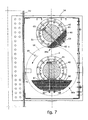
- is an enlarged detail of
fig. 4 ; - - fig. 8
- is a diagram showing on the x axis the time in seconds, and on the y axis the linear displacement in millimetres of the scrap or metal charge (left) and, respectively, the oscillatory displacement of the conveyor or conveyor channel (right).
- With reference to
fig. 1 , a pair ofidentical vibration devices 10 according to the present invention are shown applied on twocorresponding conveyor apparatuses melting plant 13 of a known type, for example of the type described in the International Patent ApplicationWO-A-2005/052196 . - Each
conveyor apparatus - The
apparatus 11, disposed farther downstream, that is, nearer to amelting furnace 15, for example of the electric arc type, also of a known type, is inserted for a good part of its length in a preheatingtunnel 16, in which the scrap is able to be preheated, for example using the fumes produced by the meltingfurnace 15. - Each
apparatus 11, 12 (figs. 1 and 2 ) comprises a bearingstructure 20, oblong and substantially horizontal, on the front part of which a conveyor channel 21 (fig. 2 ) is fixed, having a substantially U-shaped cross section, and made of metal sheets welded together in such a manner that there are no welding beads at least on its inner surfaces. - For the purposes of the present invention, the
apparatuses - The bearing
structure 20 is supported by a plurality oftie rods 27 supported byvertical pillars 29 fixed to a base 30 (fig. 1 ) of theplant 11, and can oscillate both in a longitudinal direction (axis X,figs. 1 ,3 and 4 ), and also in a transverse direction (axis Y,figs. 2 and4 ), remaining substantially horizontal. - Each vibration device 10 (
figs. 3, 4 and5 ) is mounted at one of the two ends of the corresponding bearingstructure 20 and is able to impart to the latter and to the conveyor channel 21 a vibratory or oscillating motion, at determinate frequencies and accelerations, such as to make the mass of metal charge (about 30 tonnes) advance longitudinally and in a substantially continuous manner at a speed of about 100 mm/s (see graph infig. 6 ), so as to convey to the melting furnace 15 (fig. 1 ) about 3 tonnes per minute for scrap iron and up to 6 tonnes per minute for other types of charges, preheated in thetunnel 16. - Each vibration device 10 (
figs. 3, 4 ,5, 6 and7 ) essentially comprises twogroups structure 20. Eachgroup eccentric masses fig. 5 ) able to rotate in reciprocally opposite directions and in synchrony with each other. Eacheccentric mass corresponding bearing shaft - The
shafts 40 and 41 are coupled together by means of twogears transmission belt 48, to a firstelectric motor 49, of a known type. The transmission ratio between the pinion of theelectric motor 49 and the pulley keyed onto the shaft 41 is 3:1, so that when the pinion of themotor 49 rotates at a frequency of 12 Hz, the shaft 41 and theeccentric mass 36a have a frequency of 4 Hz, while theshaft 40 and theeccentric mass 35a have a frequency of 8 Hz. - In the same way, the
shafts gears shaft 43 is also connected by means of atransmission belt 58 to a secondelectric motor 59, identical to themotor 49. The transmission ratio between the pinion of theelectric motor 59 and the pulley keyed onto theshaft 43 is also 3:1, so that the same considerations on the frequencies of rotation of theeccentric masses eccentric masses - Moreover, the bearing
shafts bar 50, (fig. 4 ), and two pairs ofbevel gears eccentric masses bar 50 comprises two coaxial semi-axles, connected by an elastic joint 53, of a known type, which is able to dampen the torsional vibrations in the range of frequencies around 2 Hz. - Each
eccentric mass fig. 7 ) kept packed in a correspondinglateral seating 61 of theshafts bolts shafts - Advantageously, the first
eccentric masses eccentric masses structure 20, theconveyor channel 21 and thevibration device 10 has an overall weight of about 100 tonnes, then the weight of each firsteccentric mass eccentric mass - Advantageously, with respect to the direction of feed of the metal charge, the heavier
eccentric masses eccentric masses - Moreover, each first
eccentric mass eccentric mass - In addition, the phase displacement of the first
eccentric masses eccentric masses - The
electric motors device 10, when thewhole bearing structure 20 is to be set in motion, or one at a time, when theconveyor apparatus - During the start-up step, each pair of
eccentric masses recognition marker 69, for example disposed on thetoothed wheels sensors 70 disposed in a fixed position. In the angular reference position the secondeccentric mass eccentric masses fig. 6 ), which passes through the axes of rotation of the bearingshafts 40, 41; 42, 43 and which is inclined by an angle α, of about 45°, on symmetrically opposite sides, with respect to the longitudinal direction X. The value of the angle α is a function of the overall mass and the rigidity of the parts in motion of theconveyor apparatus vibration device 10 is mounted. - Moreover, in the start-up step of the
device 10, theelectric motors eccentric masses structure 20, in order to prevent the generation of forces that can cause vertical accelerations on the bearingstructure 20 itself. Subsequently, once the angular reference position has been reached, theelectric motors eccentric masses structure 20 and the associatedconveyor channel 21 the desired vibratory or oscillatory motion, as shown in the graph infig. 8 , which causes the substantially continuous advance of the metal charge. - It is clear that modifications and/or additions of parts may be made to the
vibration device 10 as described heretofore, without departing from the field and scope of the present invention. - It is also clear that, although the present invention has been described with reference to a specific example, a person of skill in the art shall certainly be able to achieve many other equivalent forms of vibration device for conveyor apparatuses for conveying a metal charge in a melting plant, having the characteristics as set forth in the following claims and hence all coming within the field of protection defined thereby.
Claims (15)
- vibration device for a conveyor apparatus able to convey a metal charge, towards a container (15) of a melting plant (13), wherein said conveyor apparatus comprises at least a bearing structure (20), substantially oblong, with associated conveyor channel (21) and supported by supporting elements (27) which allow said conveyor channel (21) to oscillate, or vibrate, at least in a longitudinal direction (X), remaining substantially horizontal, and wherein said vibration device (10) is fixed to said bearing structure (20) and comprises at least a first pair of eccentric masses (35a, 36a) mounted off-axis on two corresponding bearing shafts (40, 41) able to rotate in synchrony with each other, and a second pair of eccentric masses (35b, 36b) mounted off-axis on two corresponding bearing shafts (42, 43), said bearing shafts (40, 41, 42, 43) being able to rotate in synchrony with each other for causing, due to the effect of the centrifugal forces generated by said eccentric masses (35a, 36a; 35b, 36b), a vibratory motion, at a determinate frequency, of said bearing structure (20) and of the associated conveyor channel (21) in order to feed in this way said metal charge with respect to said conveyor channel (21), in a substantially constant manner, towards said container (15), wherein at least a first eccentric mass (35a) of said first pair of eccentric masses (35a, 36a) is angularly out-of-phase by an angle (ϕ) other than zero, with respect to the second eccentric mass (36a) of the same pair of eccentric masses (35a, 36a), characterized in that during the start-up step, each pair of said eccentric masses (35a, 36a; 35b, 36b) is able to be positioned in a determinate angular reference position with respect to said longitudinal direction (X).
- Vibration device as in claim 1, characterized in that said two pairs of eccentric masses (35a, 36a; 35b, 36b) are commanded by two corresponding electric motors (49, 59), each of which is able to be energized and controlled individually or in synchrony with the other electric motor.
- Vibration device as in claim 2, characterized in that each of said electric motors (49, 59) is connected to a first of said bearing shafts (41, 43) of the corresponding pair of eccentric masses (35a, 36a; 35b, 36b), while the other of said bearing shafts (40, 2) of the corresponding pair of eccentric masses (35a, 36a; 35b, 36b) is engaged with the corresponding first bearing shaft (41, 43).
- Vibration device as in claim 2 or 3, characterized in that said two electric motors (49, 59) are able to rotate in reciprocally opposite directions.
- Vibration device as in any claim hereinbefore, characterized in that for each pair of said eccentric masses (35a, 36a; 35b, 36b) said first eccentric mass (35a, 35b) is able to rotate at an angular velocity double that of said second eccentric mass (36a, 36b).
- Vibration device as in claim 1, characterized in that in said angular reference position the second eccentric mass (36a, 36b) of each pair of said eccentric masses (35a, 36a; 35b, 36b) has its baricenter lying substantially on an axis (a, b) which passes through the axis of rotation of the corresponding bearing shaft (41, 43) and which is angled by a predetermined value (α) with respect to said longitudinal direction (X), and that said predetermined value (α) is a function of the overall mass of the parts in motion of said conveyor apparatus (11, 12) and its rigidity.
- Vibration device as in claims 1 and 2, characterized in that during said start-up step, said electric motors (49, 59) are able to make said eccentric masses (35a, 36a; 35b, 36b) rotate first slowly towards said angular reference position, substantially without causing any oscillation on said bearing structure (20), and subsequently to impart to them the acceleration necessary to cause said vibratory motion.
- Vibration device as in claim 7, characterized in that sensor means (70) are able to detect said angular reference position in order to consequently command said electric motors (49, 59).
- Vibration device as in any claim hereinbefore, wherein the weight of said bearing structure (20) and of the relative conveyor channel (21) is of the order of about 100 tonnes, characterized in that each first eccentric mass (35a, 35b) weighs about 600-650 Kg, in that each second eccentric mass (36a, 36b) weighs about 2,000-2,400 Kg and in that, to impart said acceleration, said electric motors (49, 59) are able to be fed so as to each deliver a power comprised between 30 and 40 KW, advantageously about 37 KW at about 600 rpm.
- Vibration device as in claim 1, characterized in that each of said eccentric masses (35a, 36a; 35b, 36b) comprises a plurality of metal sheets (60) packed together and fixed on a lateral longitudinal seating (61) of the corresponding bearing shaft (40, 41, 42, 43).
- Vibration device as in claim 10, characterized in that each plurality of metal sheets (60) is fixed to the corresponding bearing shaft (40, 41, 42, 43) by means of two longitudinal rows of clamping elements (62, 63) disposed on opposite sides and substantially equidistant from the axis of rotation of the corresponding bearing shaft (40, 41, 42, 43).
- Vibration device as in claim 11, characterized in that said clamping elements comprise a plurality of bolts having the end opposite said metal sheets (60) associated with constraining means (65) which prevent the rotation thereof.
- Vibration device as in claim 12, characterized in that said constraining means comprise, for each bolt (62, 63), a transverse element (65) which captures the corresponding threaded nut.
- Vibration device as in claim 1 characterized in that, with respect to the direction of feed of said metal charge, each heavier eccentric mass (36a; 36b) is disposed upstream with respect to the corresponding lighter eccentric mass (35a; 35b).
- Method for determining the start-up angular reference position of at least a pair of eccentric masses (35a, 36a; 35b, 36b) of a vibration device for a conveyor apparatus able to convey a metal charge towards a container (15) of a melting plant (13), wherein said conveyor apparatus comprises at least a bearing structure (20), substantially oblong, with associated conveyor channel (21) and supported by supporting elements (27) which allow it to oscillate, or vibrate, at least in a longitudinal direction (X), remaining substantially horizontal, and wherein said pair of eccentric masses (35a, 36a; 35b, 36b) is mounted off-axis on two corresponding bearing shafts (40, 41; 42, 43) able to rotate by at least an electric motor (49; 59) in synchrony with each other for causing, due to the effect of the centrifugal forces generated by said eccentric masses (35a, 36a; 35b, 36b), a vibratory motion, at a determinate frequency, of said bearing structure (20) and of the associated conveyor channel (21) in order to feed in this way said metal charge with respect to said conveyor channel (21), in a substantially constant manner, towards said container (15), wherein at least a first eccentric mass (35a; 35b) of said first pair of eccentric masses (35a, 36a; 35b, 36b) is angularly out-of-phase by an angle (ϕ) other than zero, with respect to the second eccentric mass (36a; 36b), characterized in that during a start-up step, said pair of eccentric masses (35a, 36a; 35b, 36b) is to be positioned in a determinate start-up angular reference position with respect to said longitudinal direction (X), and wherein said method comprises a first step during which said eccentric masses (35a, 36a; 35b, 36b) are disposed in a first angular position, substantially random; a second step wherein, with said eccentric masses (35a, 36a; 35b, 36b) in said first angular position, the corresponding electric motor (49; 59) is fed with maximum power and the vertical acceleration is measured on the end of said bearing structure (20) on which the vibration device (10) is mounted, after which said electric motor (49; 59) is stopped; a third step wherein said eccentric masses (35a, 36a; 35b, 36b) are disposed in a second angular position, rotated by a determinate angle with respect to said first angular position; a fourth step wherein said electric motor (49; 59) are restarted with maximum power and said vertical acceleration is again measured; a fifth step wherein the third and fourth steps are repeated, with new angular positions of said eccentric masses (35a, 36a; 35b, 36b) until the round angle of said eccentric masses (35a, 36a; 35b, 36b) is completed; and a final step at the end of said measurements, wherein said angular reference position is determined, which corresponds to that in which the lowest value of said vertical acceleration has been detected.
Applications Claiming Priority (2)
| Application Number | Priority Date | Filing Date | Title |
|---|---|---|---|
| IT000020A ITUD20050020A1 (en) | 2005-02-22 | 2005-02-22 | VIBRATION DEVICE FOR AN INVOLVEMENT EQUIPMENT OF A METALLIC CHARGE IN A MERGER PLANT |
| PCT/EP2006/060081 WO2006089865A1 (en) | 2005-02-22 | 2006-02-17 | Vibration device for an apparatus for conveying a metal charge in a melting plant |
Publications (3)
| Publication Number | Publication Date |
|---|---|
| EP1851142A1 EP1851142A1 (en) | 2007-11-07 |
| EP1851142B1 true EP1851142B1 (en) | 2010-08-04 |
| EP1851142B2 EP1851142B2 (en) | 2016-01-27 |
Family
ID=34978916
Family Applications (1)
| Application Number | Title | Priority Date | Filing Date |
|---|---|---|---|
| EP06708369.1A Expired - Lifetime EP1851142B2 (en) | 2005-02-22 | 2006-02-17 | Vibration device for an apparatus for conveying a metal charge in a melting plant |
Country Status (7)
| Country | Link |
|---|---|
| EP (1) | EP1851142B2 (en) |
| AT (1) | ATE476384T2 (en) |
| DE (1) | DE602006015918D1 (en) |
| ES (1) | ES2349995T5 (en) |
| IT (1) | ITUD20050020A1 (en) |
| MX (1) | MX2007010206A (en) |
| WO (1) | WO2006089865A1 (en) |
Families Citing this family (3)
| Publication number | Priority date | Publication date | Assignee | Title |
|---|---|---|---|---|
| ITUD20120056A1 (en) * | 2012-04-04 | 2013-10-05 | Danieli Off Mecc | VIBRATION DEVICE FOR CONVEYING EQUIPMENT OF A METALLIC CHARGE IN A MERGER PLANT |
| CN110171671B (en) * | 2019-06-26 | 2024-05-07 | 中冶赛迪工程技术股份有限公司 | Excitation module and vibration exciter |
| NL1044184B1 (en) * | 2021-10-18 | 2023-05-16 | Foodeq Eng Bv | Optimization and monitoring control for imbalance vibration technology. |
Family Cites Families (5)
| Publication number | Priority date | Publication date | Assignee | Title |
|---|---|---|---|---|
| GB1084304A (en) * | ||||
| DE4219648A1 (en) * | 1991-07-10 | 1993-01-14 | Klein Alb Gmbh Co Kg | Controlling vibrating system e.g. crusher, conveyor chute - generating equal and opposite vibrations to minimise emanations, esp. of air or sound vibrations |
| EP0650909A1 (en) * | 1993-10-27 | 1995-05-03 | Jöst GmbH + Co. KG | Vibratory conveyor |
| DE4417162C1 (en) * | 1994-05-17 | 1995-08-17 | Uhde Gmbh | Vibrating conveyor for sorting material |
| US5938001A (en) * | 1997-01-16 | 1999-08-17 | Fmc Corporation | Vibratory conveyor apparatus with phase-optimized conveyor drive |
-
2005
- 2005-02-22 IT IT000020A patent/ITUD20050020A1/en unknown
-
2006
- 2006-02-17 AT AT06708369T patent/ATE476384T2/en active
- 2006-02-17 MX MX2007010206A patent/MX2007010206A/en active IP Right Grant
- 2006-02-17 ES ES06708369.1T patent/ES2349995T5/en not_active Expired - Lifetime
- 2006-02-17 EP EP06708369.1A patent/EP1851142B2/en not_active Expired - Lifetime
- 2006-02-17 DE DE602006015918T patent/DE602006015918D1/en not_active Expired - Lifetime
- 2006-02-17 WO PCT/EP2006/060081 patent/WO2006089865A1/en not_active Ceased
Also Published As
| Publication number | Publication date |
|---|---|
| DE602006015918D1 (en) | 2010-09-16 |
| ES2349995T3 (en) | 2011-01-14 |
| ATE476384T2 (en) | 2010-08-15 |
| EP1851142B2 (en) | 2016-01-27 |
| ES2349995T5 (en) | 2016-04-25 |
| EP1851142A1 (en) | 2007-11-07 |
| WO2006089865A1 (en) | 2006-08-31 |
| MX2007010206A (en) | 2008-03-07 |
| ITUD20050020A1 (en) | 2006-08-23 |
Similar Documents
| Publication | Publication Date | Title |
|---|---|---|
| US5131525A (en) | Vibratory conveyor | |
| EP2998245B1 (en) | Vibratory conveyor | |
| US5024320A (en) | Vibratory spiral elevator | |
| EP1851142B2 (en) | Vibration device for an apparatus for conveying a metal charge in a melting plant | |
| US20140283633A1 (en) | Vibration exciter, in particular for a construction machine | |
| EP3785001B1 (en) | Resonant fatigue testing | |
| US9776804B2 (en) | Vibration device for an apparatus for conveying a metal charge to a melting plant | |
| US5924918A (en) | Device for processing poultry bodies | |
| US3212629A (en) | Vibratory conveyor, particularly bin-discharge conveyor | |
| WO2006089897A1 (en) | Conveyor apparatus for conveying a metal charge in a melting plant | |
| EP4245699A1 (en) | Anti-resonance reversible vibrating conveyor | |
| RU2166366C1 (en) | Grinding device | |
| JPH05319537A (en) | Vibrating conveyor | |
| US2751068A (en) | Haddox | |
| CN110775520A (en) | Roller conveyer belt for automatic batching system | |
| JPS5849442B2 (en) | vibrating conveyor | |
| US712335A (en) | Conveyer. | |
| SU1743646A1 (en) | Method and device for separation of friable materials | |
| CN115258515A (en) | External rapping device for assisting coal dropping pipe dredging | |
| RU2346745C1 (en) | Centrifugal mill | |
| JPS5913406B2 (en) | Vibrating parts conveyor | |
| JPS5849443B2 (en) | Vibrating parts feeding machine | |
| JPS5832124B2 (en) | Vibrating parts conveyor | |
| HK1200402B (en) | A vibration generator for a construction machine | |
| JPS591645B2 (en) | Vibrating parts conveyor |
Legal Events
| Date | Code | Title | Description |
|---|---|---|---|
| PUAI | Public reference made under article 153(3) epc to a published international application that has entered the european phase |
Free format text: ORIGINAL CODE: 0009012 |
|
| 17P | Request for examination filed |
Effective date: 20070905 |
|
| AK | Designated contracting states |
Kind code of ref document: A1 Designated state(s): AT BE BG CH CY CZ DE DK EE ES FI FR GB GR HU IE IS IT LI LT LU LV MC NL PL PT RO SE SI SK TR |
|
| DAX | Request for extension of the european patent (deleted) | ||
| 17Q | First examination report despatched |
Effective date: 20081113 |
|
| GRAP | Despatch of communication of intention to grant a patent |
Free format text: ORIGINAL CODE: EPIDOSNIGR1 |
|
| GRAS | Grant fee paid |
Free format text: ORIGINAL CODE: EPIDOSNIGR3 |
|
| GRAA | (expected) grant |
Free format text: ORIGINAL CODE: 0009210 |
|
| AK | Designated contracting states |
Kind code of ref document: B1 Designated state(s): AT BE BG CH CY CZ DE DK EE ES FI FR GB GR HU IE IS IT LI LT LU LV MC NL PL PT RO SE SI SK TR |
|
| REG | Reference to a national code |
Ref country code: GB Ref legal event code: FG4D |
|
| REG | Reference to a national code |
Ref country code: CH Ref legal event code: EP |
|
| REG | Reference to a national code |
Ref country code: IE Ref legal event code: FG4D |
|
| REF | Corresponds to: |
Ref document number: 602006015918 Country of ref document: DE Date of ref document: 20100916 Kind code of ref document: P |
|
| REG | Reference to a national code |
Ref country code: NL Ref legal event code: VDEP Effective date: 20100804 |
|
| REG | Reference to a national code |
Ref country code: ES Ref legal event code: FG2A Effective date: 20110103 |
|
| LTIE | Lt: invalidation of european patent or patent extension |
Effective date: 20100804 |
|
| PG25 | Lapsed in a contracting state [announced via postgrant information from national office to epo] |
Ref country code: NL Free format text: LAPSE BECAUSE OF FAILURE TO SUBMIT A TRANSLATION OF THE DESCRIPTION OR TO PAY THE FEE WITHIN THE PRESCRIBED TIME-LIMIT Effective date: 20100804 Ref country code: LT Free format text: LAPSE BECAUSE OF FAILURE TO SUBMIT A TRANSLATION OF THE DESCRIPTION OR TO PAY THE FEE WITHIN THE PRESCRIBED TIME-LIMIT Effective date: 20100804 Ref country code: FI Free format text: LAPSE BECAUSE OF FAILURE TO SUBMIT A TRANSLATION OF THE DESCRIPTION OR TO PAY THE FEE WITHIN THE PRESCRIBED TIME-LIMIT Effective date: 20100804 |
|
| PG25 | Lapsed in a contracting state [announced via postgrant information from national office to epo] |
Ref country code: PL Free format text: LAPSE BECAUSE OF FAILURE TO SUBMIT A TRANSLATION OF THE DESCRIPTION OR TO PAY THE FEE WITHIN THE PRESCRIBED TIME-LIMIT Effective date: 20100804 Ref country code: SI Free format text: LAPSE BECAUSE OF FAILURE TO SUBMIT A TRANSLATION OF THE DESCRIPTION OR TO PAY THE FEE WITHIN THE PRESCRIBED TIME-LIMIT Effective date: 20100804 Ref country code: BG Free format text: LAPSE BECAUSE OF FAILURE TO SUBMIT A TRANSLATION OF THE DESCRIPTION OR TO PAY THE FEE WITHIN THE PRESCRIBED TIME-LIMIT Effective date: 20101104 Ref country code: IS Free format text: LAPSE BECAUSE OF FAILURE TO SUBMIT A TRANSLATION OF THE DESCRIPTION OR TO PAY THE FEE WITHIN THE PRESCRIBED TIME-LIMIT Effective date: 20101204 Ref country code: CY Free format text: LAPSE BECAUSE OF FAILURE TO SUBMIT A TRANSLATION OF THE DESCRIPTION OR TO PAY THE FEE WITHIN THE PRESCRIBED TIME-LIMIT Effective date: 20100804 Ref country code: PT Free format text: LAPSE BECAUSE OF FAILURE TO SUBMIT A TRANSLATION OF THE DESCRIPTION OR TO PAY THE FEE WITHIN THE PRESCRIBED TIME-LIMIT Effective date: 20101206 |
|
| PG25 | Lapsed in a contracting state [announced via postgrant information from national office to epo] |
Ref country code: LV Free format text: LAPSE BECAUSE OF FAILURE TO SUBMIT A TRANSLATION OF THE DESCRIPTION OR TO PAY THE FEE WITHIN THE PRESCRIBED TIME-LIMIT Effective date: 20100804 Ref country code: SE Free format text: LAPSE BECAUSE OF FAILURE TO SUBMIT A TRANSLATION OF THE DESCRIPTION OR TO PAY THE FEE WITHIN THE PRESCRIBED TIME-LIMIT Effective date: 20100804 Ref country code: BE Free format text: LAPSE BECAUSE OF FAILURE TO SUBMIT A TRANSLATION OF THE DESCRIPTION OR TO PAY THE FEE WITHIN THE PRESCRIBED TIME-LIMIT Effective date: 20100804 Ref country code: GR Free format text: LAPSE BECAUSE OF FAILURE TO SUBMIT A TRANSLATION OF THE DESCRIPTION OR TO PAY THE FEE WITHIN THE PRESCRIBED TIME-LIMIT Effective date: 20101105 |
|
| PG25 | Lapsed in a contracting state [announced via postgrant information from national office to epo] |
Ref country code: DK Free format text: LAPSE BECAUSE OF FAILURE TO SUBMIT A TRANSLATION OF THE DESCRIPTION OR TO PAY THE FEE WITHIN THE PRESCRIBED TIME-LIMIT Effective date: 20100804 |
|
| PLBI | Opposition filed |
Free format text: ORIGINAL CODE: 0009260 |
|
| PG25 | Lapsed in a contracting state [announced via postgrant information from national office to epo] |
Ref country code: RO Free format text: LAPSE BECAUSE OF FAILURE TO SUBMIT A TRANSLATION OF THE DESCRIPTION OR TO PAY THE FEE WITHIN THE PRESCRIBED TIME-LIMIT Effective date: 20100804 Ref country code: EE Free format text: LAPSE BECAUSE OF FAILURE TO SUBMIT A TRANSLATION OF THE DESCRIPTION OR TO PAY THE FEE WITHIN THE PRESCRIBED TIME-LIMIT Effective date: 20100804 Ref country code: CZ Free format text: LAPSE BECAUSE OF FAILURE TO SUBMIT A TRANSLATION OF THE DESCRIPTION OR TO PAY THE FEE WITHIN THE PRESCRIBED TIME-LIMIT Effective date: 20100804 Ref country code: SK Free format text: LAPSE BECAUSE OF FAILURE TO SUBMIT A TRANSLATION OF THE DESCRIPTION OR TO PAY THE FEE WITHIN THE PRESCRIBED TIME-LIMIT Effective date: 20100804 |
|
| 26 | Opposition filed |
Opponent name: TENOVA S.P.A. Effective date: 20110426 |
|
| PLAX | Notice of opposition and request to file observation + time limit sent |
Free format text: ORIGINAL CODE: EPIDOSNOBS2 |
|
| REG | Reference to a national code |
Ref country code: DE Ref legal event code: R026 Ref document number: 602006015918 Country of ref document: DE Effective date: 20110426 |
|
| PG25 | Lapsed in a contracting state [announced via postgrant information from national office to epo] |
Ref country code: MC Free format text: LAPSE BECAUSE OF NON-PAYMENT OF DUE FEES Effective date: 20110228 |
|
| PLAF | Information modified related to communication of a notice of opposition and request to file observations + time limit |
Free format text: ORIGINAL CODE: EPIDOSCOBS2 |
|
| REG | Reference to a national code |
Ref country code: IE Ref legal event code: MM4A |
|
| PLBB | Reply of patent proprietor to notice(s) of opposition received |
Free format text: ORIGINAL CODE: EPIDOSNOBS3 |
|
| PG25 | Lapsed in a contracting state [announced via postgrant information from national office to epo] |
Ref country code: IE Free format text: LAPSE BECAUSE OF NON-PAYMENT OF DUE FEES Effective date: 20110217 |
|
| PG25 | Lapsed in a contracting state [announced via postgrant information from national office to epo] |
Ref country code: LU Free format text: LAPSE BECAUSE OF NON-PAYMENT OF DUE FEES Effective date: 20110217 |
|
| PG25 | Lapsed in a contracting state [announced via postgrant information from national office to epo] |
Ref country code: HU Free format text: LAPSE BECAUSE OF FAILURE TO SUBMIT A TRANSLATION OF THE DESCRIPTION OR TO PAY THE FEE WITHIN THE PRESCRIBED TIME-LIMIT Effective date: 20100804 |
|
| PGFP | Annual fee paid to national office [announced via postgrant information from national office to epo] |
Ref country code: CH Payment date: 20150126 Year of fee payment: 10 |
|
| PGFP | Annual fee paid to national office [announced via postgrant information from national office to epo] |
Ref country code: GB Payment date: 20150123 Year of fee payment: 10 |
|
| PUAH | Patent maintained in amended form |
Free format text: ORIGINAL CODE: 0009272 |
|
| STAA | Information on the status of an ep patent application or granted ep patent |
Free format text: STATUS: PATENT MAINTAINED AS AMENDED |
|
| REG | Reference to a national code |
Ref country code: FR Ref legal event code: PLFP Year of fee payment: 11 |
|
| 27A | Patent maintained in amended form |
Effective date: 20160127 |
|
| AK | Designated contracting states |
Kind code of ref document: B2 Designated state(s): AT BE BG CH CY CZ DE DK EE ES FI FR GB GR HU IE IS IT LI LT LU LV MC NL PL PT RO SE SI SK TR |
|
| REG | Reference to a national code |
Ref country code: DE Ref legal event code: R102 Ref document number: 602006015918 Country of ref document: DE |
|
| REG | Reference to a national code |
Ref country code: CH Ref legal event code: AELC |
|
| REG | Reference to a national code |
Ref country code: ES Ref legal event code: DC2A Ref document number: 2349995 Country of ref document: ES Kind code of ref document: T5 Effective date: 20160425 |
|
| REG | Reference to a national code |
Ref country code: CH Ref legal event code: PL |
|
| GBPC | Gb: european patent ceased through non-payment of renewal fee |
Effective date: 20160217 |
|
| PG25 | Lapsed in a contracting state [announced via postgrant information from national office to epo] |
Ref country code: CH Free format text: LAPSE BECAUSE OF NON-PAYMENT OF DUE FEES Effective date: 20160229 Ref country code: LI Free format text: LAPSE BECAUSE OF NON-PAYMENT OF DUE FEES Effective date: 20160229 |
|
| REG | Reference to a national code |
Ref country code: FR Ref legal event code: PLFP Year of fee payment: 12 |
|
| PG25 | Lapsed in a contracting state [announced via postgrant information from national office to epo] |
Ref country code: GB Free format text: LAPSE BECAUSE OF NON-PAYMENT OF DUE FEES Effective date: 20160217 |
|
| REG | Reference to a national code |
Ref country code: FR Ref legal event code: PLFP Year of fee payment: 13 |
|
| REG | Reference to a national code |
Ref country code: AT Ref legal event code: UEP Ref document number: 476384 Country of ref document: AT Kind code of ref document: T Effective date: 20160127 |
|
| PGFP | Annual fee paid to national office [announced via postgrant information from national office to epo] |
Ref country code: FR Payment date: 20190322 Year of fee payment: 8 |
|
| PGFP | Annual fee paid to national office [announced via postgrant information from national office to epo] |
Ref country code: ES Payment date: 20200302 Year of fee payment: 15 Ref country code: AT Payment date: 20200123 Year of fee payment: 15 |
|
| PGFP | Annual fee paid to national office [announced via postgrant information from national office to epo] |
Ref country code: TR Payment date: 20210128 Year of fee payment: 16 |
|
| PG25 | Lapsed in a contracting state [announced via postgrant information from national office to epo] |
Ref country code: FR Free format text: LAPSE BECAUSE OF NON-PAYMENT OF DUE FEES Effective date: 20200302 |
|
| REG | Reference to a national code |
Ref country code: AT Ref legal event code: MM01 Ref document number: 476384 Country of ref document: AT Kind code of ref document: T Effective date: 20210217 |
|
| PG25 | Lapsed in a contracting state [announced via postgrant information from national office to epo] |
Ref country code: AT Free format text: LAPSE BECAUSE OF NON-PAYMENT OF DUE FEES Effective date: 20210217 |
|
| REG | Reference to a national code |
Ref country code: ES Ref legal event code: FD2A Effective date: 20220513 |
|
| PG25 | Lapsed in a contracting state [announced via postgrant information from national office to epo] |
Ref country code: ES Free format text: LAPSE BECAUSE OF NON-PAYMENT OF DUE FEES Effective date: 20210218 |
|
| P01 | Opt-out of the competence of the unified patent court (upc) registered |
Effective date: 20230516 |
|
| PGFP | Annual fee paid to national office [announced via postgrant information from national office to epo] |
Ref country code: DE Payment date: 20240228 Year of fee payment: 19 |
|
| PG25 | Lapsed in a contracting state [announced via postgrant information from national office to epo] |
Ref country code: TR Free format text: LAPSE BECAUSE OF NON-PAYMENT OF DUE FEES Effective date: 20220217 |
|
| PGFP | Annual fee paid to national office [announced via postgrant information from national office to epo] |
Ref country code: IT Payment date: 20250220 Year of fee payment: 20 |
|
| REG | Reference to a national code |
Ref country code: DE Ref legal event code: R119 Ref document number: 602006015918 Country of ref document: DE |
|
| PG25 | Lapsed in a contracting state [announced via postgrant information from national office to epo] |
Ref country code: DE Free format text: LAPSE BECAUSE OF NON-PAYMENT OF DUE FEES Effective date: 20250902 |