EP1850532B1 - Method of providing a guest terminal with emergency access over a WLAN - Google Patents
Method of providing a guest terminal with emergency access over a WLAN Download PDFInfo
- Publication number
- EP1850532B1 EP1850532B1 EP06360015A EP06360015A EP1850532B1 EP 1850532 B1 EP1850532 B1 EP 1850532B1 EP 06360015 A EP06360015 A EP 06360015A EP 06360015 A EP06360015 A EP 06360015A EP 1850532 B1 EP1850532 B1 EP 1850532B1
- Authority
- EP
- European Patent Office
- Prior art keywords
- emergency
- terminal
- ssid
- data packets
- lan
- Prior art date
- Legal status (The legal status is an assumption and is not a legal conclusion. Google has not performed a legal analysis and makes no representation as to the accuracy of the status listed.)
- Active
Links
- 238000000034 method Methods 0.000 title claims abstract description 68
- 238000000060 site-specific infrared dichroism spectroscopy Methods 0.000 claims abstract description 45
- 238000004891 communication Methods 0.000 claims abstract description 33
- 230000004044 response Effects 0.000 claims description 12
- 230000000977 initiatory effect Effects 0.000 claims description 6
- 238000009432 framing Methods 0.000 claims description 3
- 230000004807 localization Effects 0.000 description 60
- 230000006870 function Effects 0.000 description 45
- 239000000344 soap Substances 0.000 description 13
- 230000008569 process Effects 0.000 description 9
- 230000005540 biological transmission Effects 0.000 description 5
- 230000007246 mechanism Effects 0.000 description 5
- 230000011664 signaling Effects 0.000 description 5
- 238000001514 detection method Methods 0.000 description 4
- 230000009471 action Effects 0.000 description 3
- 238000010586 diagram Methods 0.000 description 3
- 101100048435 Caenorhabditis elegans unc-18 gene Proteins 0.000 description 2
- 238000013459 approach Methods 0.000 description 2
- 230000008901 benefit Effects 0.000 description 2
- 230000001413 cellular effect Effects 0.000 description 2
- 230000008859 change Effects 0.000 description 2
- 230000001419 dependent effect Effects 0.000 description 2
- 238000002955 isolation Methods 0.000 description 2
- 230000004048 modification Effects 0.000 description 2
- 238000012986 modification Methods 0.000 description 2
- 102100035024 Carboxypeptidase B Human genes 0.000 description 1
- 101000946524 Homo sapiens Carboxypeptidase B Proteins 0.000 description 1
- 239000004165 Methyl ester of fatty acids Substances 0.000 description 1
- 108010007100 Pulmonary Surfactant-Associated Protein A Proteins 0.000 description 1
- 102100027773 Pulmonary surfactant-associated protein A2 Human genes 0.000 description 1
- 230000001154 acute effect Effects 0.000 description 1
- 238000013475 authorization Methods 0.000 description 1
- 239000003795 chemical substances by application Substances 0.000 description 1
- 230000009849 deactivation Effects 0.000 description 1
- 230000007123 defense Effects 0.000 description 1
- 238000011161 development Methods 0.000 description 1
- 238000005516 engineering process Methods 0.000 description 1
- 238000001914 filtration Methods 0.000 description 1
- 230000010354 integration Effects 0.000 description 1
- 238000010295 mobile communication Methods 0.000 description 1
- 230000006855 networking Effects 0.000 description 1
- 238000012545 processing Methods 0.000 description 1
- 238000000926 separation method Methods 0.000 description 1
- 238000001228 spectrum Methods 0.000 description 1
- 230000003068 static effect Effects 0.000 description 1
- 238000013519 translation Methods 0.000 description 1
- 230000001960 triggered effect Effects 0.000 description 1
Images


Classifications
-
- H—ELECTRICITY
- H04—ELECTRIC COMMUNICATION TECHNIQUE
- H04W—WIRELESS COMMUNICATION NETWORKS
- H04W4/00—Services specially adapted for wireless communication networks; Facilities therefor
- H04W4/90—Services for handling of emergency or hazardous situations, e.g. earthquake and tsunami warning systems [ETWS]
-
- H—ELECTRICITY
- H04—ELECTRIC COMMUNICATION TECHNIQUE
- H04W—WIRELESS COMMUNICATION NETWORKS
- H04W40/00—Communication routing or communication path finding
- H04W40/02—Communication route or path selection, e.g. power-based or shortest path routing
-
- H—ELECTRICITY
- H04—ELECTRIC COMMUNICATION TECHNIQUE
- H04W—WIRELESS COMMUNICATION NETWORKS
- H04W48/00—Access restriction; Network selection; Access point selection
- H04W48/20—Selecting an access point
-
- H—ELECTRICITY
- H04—ELECTRIC COMMUNICATION TECHNIQUE
- H04W—WIRELESS COMMUNICATION NETWORKS
- H04W76/00—Connection management
- H04W76/50—Connection management for emergency connections
-
- H—ELECTRICITY
- H04—ELECTRIC COMMUNICATION TECHNIQUE
- H04W—WIRELESS COMMUNICATION NETWORKS
- H04W84/00—Network topologies
- H04W84/02—Hierarchically pre-organised networks, e.g. paging networks, cellular networks, WLAN [Wireless Local Area Network] or WLL [Wireless Local Loop]
- H04W84/10—Small scale networks; Flat hierarchical networks
- H04W84/12—WLAN [Wireless Local Area Networks]
-
- H—ELECTRICITY
- H04—ELECTRIC COMMUNICATION TECHNIQUE
- H04W—WIRELESS COMMUNICATION NETWORKS
- H04W12/00—Security arrangements; Authentication; Protecting privacy or anonymity
- H04W12/08—Access security
-
- H—ELECTRICITY
- H04—ELECTRIC COMMUNICATION TECHNIQUE
- H04W—WIRELESS COMMUNICATION NETWORKS
- H04W12/00—Security arrangements; Authentication; Protecting privacy or anonymity
- H04W12/60—Context-dependent security
- H04W12/69—Identity-dependent
- H04W12/73—Access point logical identity
Definitions
- GSM Global System for Mobile Communication
- IP Internet Protocol
- VoIP Voice over IP
- codec encoding/decoding
- RTP Real-Time Transport Protocol
- VoWLAN Voice over WLAN
- US 2006/0068799 A1 which is considered to be the closest prior art, describes an "open host" wireless access system including a wireless access point (AP) that identifies the SSID from a WLAN connection request.
- a wireless service provider (WSP) is associated with the SSID.
- the AP is coupled to a demarcation switch within the access system.
- the demarcation switch includes a series of ports, where one or more ports are associated with a particular WSP.
- a WSP can connect equipment such as a router to its associated port or ports.
- the AP opens a VLAN to the designated port or ports to establish connections to the WSPS equipment based on the SSID.
- the WSP provides IP address assignments and authentication as a native process on the network such that the user experience is customizable by each WSP.
- This wireless access system is not related to the establishment of an emergency call.
- this system does not comprise initiating an emergency call by sending data packets from a terminal associated with a selected emergency SSID to one of the one or more access points whereby the data packets are addressed by the terminal to a destination address received by the terminal by means of a DHCP request.
- US 2004/0066756 A1 describes a method for user equipment (UE) resident in a wireless access network (WLAN) to obtain access to at least one other network.
- the method includes storing the identification (SSID) of the at least one other network (visited PLMNs 1-3 and home PLMNs 4 and 5) in the user equipment; transmitting from the user equipment a request for connection to one of the at least one other network; which includes an identification of at least one of the at least one other network, to the wireless access network; and in response to the wireless access network receiving the identification, the user equipment is connected to the identified at least one other network through the wireless access network.
- This method is not related to the establishment of an emergency call.
- US 2005/0185626 A1 describes a method for associating a WSTA to a service set, wherein the service set is configurable at the AP.
- Each service set is an arbitrary grouping of one or more network service parameters, and is typically configured for either VLAN or proxy mobile IP host.
- the message containing a SSID.
- the access point matches the SSID to a service set and associates the WSTA to either a home subnet or a VLAN based on the SSID.
- the default VLAN and home subset for a WSTA may be different at each AP the WSTA encounters.
- a security server is configured with a list of allowed SSIDs for each wireless station to prevent unauthorized access to a VLAN or home subnet.
- US 2004/0181692 A1 describes a wireless local area network (WLAN) communication system that includes an access point in communication with a mobile station and at least one Authentication, Authorization, and Accounting (AAA) server provides an authentication process whereby a user of the mobile station may select a WLAN service provider from among one or more WLAN service providers and/or one or more 3GPP service providers before being authenticated and further to make a decision to subscribe to the services of the selected service provider based on network service information, other than or in addition to an Service Set Identifier (SSID), associated with the selected service provider.
- SSID Service Set Identifier
- the system does not use DHCP.
- the emergency user broadcast traffic is separated from that of normal users (and the unauthenticated user does not need their group key).
- the solution should ensure that unauthenticated emergency users cannot interfere with the broadcast traffic (such as DHCP, ARP) of other authenticated users.
- the use of an "emergency SSID" is not described.
- Part 1 signaling from QSTA to QAP to identify additional information about the nature of the bandwidth request (including whether it's an emergency call).
- Part 2 proposal for providing 911 service to clients having only public security credentials.
- US 2005/0181805 A1 describes a method and system for locating an unlicensed mobile access (UMA) subscriber.
- the method enables a user of a mobile station comprising a hand-set or the like that supports voice and data access via both licensed and unlicensed radio spectrums to be located. Accordingly, services requiring location information, such as 911 services, may by accessed when operating the mobile station under both UMA and licensed wireless network (e.g., cellular) sessions.
- UMA unlicensed mobile access
- US 2005/0190892 A1 describes that in order that emergency service vehicles can be dispatched to the correct destination promptly, accurate information about the location of the caller is needed. Another problem concerns routing emergency calls to the correct destination. For emergency calls a universal code is used such as 911 in North America and 112 in Europe. This universal code cannot be used to identify the destination of the call. These problems are particularly acute for nomadic communications systems such as voice over internet protocol communications networks. That is because user terminals change network location. These problems are solved by enabling the geographical location of the emergency caller to be determined by entities within a packet-based network without the need for modification of exisiting emergency services network infrastructure.
- US 6 714 536 B1 describes methods and apparatus for allowing a packet data connection to be established by sending an indication of a network address through a telephony path.
- a protocol stack initiates the establishment of an Internet connection by sending a data segment through a public switched telephone network (PSTN) telephony path and then operates and maintains the Internet connection on a separate packet connection. Dialing digits are used to indicate the address of a remote computer or wireless device via the telephone path.
- PSTN public switched telephone network
- This invention also enables mixed PSTN/internet multimedia telephone calls.
- a screen of information automatically appears on one or both ends of the connection via the Internet.
- the object of the present invention is achieved by a method of providing a terminal with an emergency access over a WLAN to a LAN comprising one or more access points and an access control function which admits data packets from users of the WLAN associated with a first SSID to the LAN, whereby the method comprises the steps of: defining one or more emergency SSIDs dedicated to allow access to the LAN in an emergency case; initiating an emergency call by sending data packets from a terminal associated with a selected emergency SSID to one of the one or more access points whereby the data packets are addressed by the terminal to a destination address received by the terminal by means of a DHCP response; admitting, by the access control function, the data packets from the terminal associated with the selected emergency SSID to the LAN; and routing the data packets associated with the selected emergency SSID, after admission to the LAN, to an emergency answering point, whereby_the method comprises the further steps of: requesting by the terminal a particular DHCP option that will provide the terminal with an IP address of a call manager
- the association of a terminal with a SSID means that the terminal notifies within the communication over the air interface of the WLAN said SSID.
- the SSID is notified within the MAC layer part of the communication over the air interface. That means that the terminal signalizes during the communication over the air interface an SSID to the access point, the SSID that is associated with the terminal.
- the data packets from the terminal associated with the selected emergency SSID are routed, after admission to the LAN, to an emergency answering point.
- the present invention presents a simple method how to provide a terminal - both a guest terminal and an authorized terminal - with a reliable and secure access over WLAN to a LAN in the case of an emergency.
- a user of a mobile terminal is not limited to publicly accessible LANs for establishing an emergency call but may also use corporate or proprietary LANs, e.g., a corporate campus network. Thus, even a guest terminal which normally would be unauthorized to access a network with restricted access rights can set up an emergency call via the network.
- the present invention significantly contributes to the future acceptance of the VoWLAN technology since the present invention provides a WLAN with means to offer connectivity and reliability in case of an emergency.
- FCC Federal Communications Commission
- FCC Federal Communications Commission
- 9-1-1 is the official national emergency number in the USA and Canada.
- Similar requirements are discussed in many European countries where the official national emergency number is 1-1-2, for example.
- PSAP Public Safety Answering Point
- DHCP Dynamic Host Configuration Protocol
- UDP User Datagram Protocol
- a configuration file of the DHCP server comprises information about the address pool to be distributed as well as additional data about network-relevant parameters. Therefore, a terminal with often changing locations may dispense with an error-prone pre-configuration. The terminal simply establishes a connection to the WLAN and requests all relevant parameters from the DHCP server.
- the data packets from the terminal associated with the selected emergency SSID are sent by the terminal to the IP address and the port of a call manager which will route the data packets related to the emergency call to a PSAP.
- the terminal receives the address-related data of the call manager from the DHCP server.
- the terminal requests a particular DHCP option that will provide the terminal with a destination address, i.e., an IP address of the call manager.
- the terminal may send a message associated to the DHCP method to a DHCP server to ask for a destination address where to send the data packets of the emergency call.
- the terminal associated with the selected emergency SSID sets the received IP address as destination address of the data packets from the terminal associated with the selected emergency SSID.
- the destination address comprises the IP address of the call manager and a port the call manager is listening on.
- SIP Session Initiation Protocol
- the present method is totally protocol agnostic.
- the terminal only has to send RTP packets to the call manager. There is no codec nor framing negotiation.
- data packets from a terminal associated to an emergency SSID are routed, once they have been admitted to a LAN network, to an emergency service or an emergency answering point, e.g., a PSAP.
- the routing is executed by PBX or the call manager.
- the call manager Once the call manager receives an emergency call, the call manager establishes a call regarding the geographic area of the originating call. All data packets from a terminal associated to an emergency SSID which enter the LAN are routed to the emergency service or the emergency answering point, preferably independently of the originally indicated destination address of the data packets. Data packets from a terminal associated to an emergency SSID are granted access to the LAN only for the purpose of establishing an emergency call.
- said LAN may be a LAN accessible via two or more WLANs.
- Each of the WLANs may serve as an access network to the LAN environment and be associated with a separate SSID.
- the LAN may be accessible via a first WLAN by means of a first SSID, e.g., a normal SSID, and accessible via a second WLAN by means of a second SSID, e.g., an emergency SSID.
- the invention also presents a method of providing access to a LAN accessible via at least two WLANs, for a number of user terminals comprising terminals of authorized users, e.g., users belonging to a corporation, as well as terminals of guest users.
- Said first WLAN provides access to the LAN for data packets associated with a first SSID.
- Data packets from the first WLAN are filtered using an encryption method to allow only properly encrypted data packets from terminals of authorized users to the LAN and discard data packets from other terminals.
- at least one second WLAN provides access to the LAN for data packets originating from terminals of all users and associated with a second SSID. Data packets from the second WLAN are filtered to allow only data packets carrying VoIP emergency calls.
- An important information to have in an emergency service is the localization of a user initiating an emergency call. With the help of a DHCP tracker and the use of web services hosted at a localization server, this information can be transmitted to the PSAP.
- specific emergency SSIDs for emergency calls are defined, together with specific capabilities such as codecs.
- Each of the defined emergency SSIDs is associated with different capabilities, e.g., with a different codec.
- several emergency SSIDs can be configured depending on parameters that will be used for the call, e.g., one emergency SSID for G.711 and another emergency SSID for G.729.
- the user of the terminal or the intelligence of the terminal may select an emergency SSID dependent upon the associated capabilities.
- Information about the capabilities associated with a specific emergency SSID may be extracted from the broadcast of an emergency SSID.
- the information about the capabilities may be contained in the SSID itself or may be retrieved from a separate information element of the LAN.
- the call manager receives information about the processing of the data packets in the RTP header.
- QoS Quality of Service
- a direct connection to UMTS networks is possible and hence the expansion of VoWLAN services out of the scope of radio-based LANs.
- preemption can be used to favour an emergency call.
- a priority number such as an emergency number
- the calling party may expect the WLAN to process the urgent call with a higher priority than a normal subscriber conversation.
- the AP and/or the call manager recognize the priority status of the emergency call and preempt resources allocated to calls of lower priority than the emergency call in favour of the emergency call.
- the preemption and TSPEC mechanisms may be used to guarantee a specific QoS to the data packets associated with an emergency call.
- the terminal comprises a display unit, e.g., a screen, where a specific symbol, e.g., the letters "SOS" or an icon depicting a police patrol light, can be displayed on a softscreen or a dial pad when the terminal detects that an emergency SSID is available.
- a specific symbol e.g., the letters "SOS" or an icon depicting a police patrol light
- an acoustic signal e.g., a jingle or a specific sound
- a data file comprising the specific icon or sound may be stored in a memory of the terminal and may be retrieved from the memory and outputted at the terminal to inform a user of the terminal that an emergency access to the WLAN is available.
- At least one of the one or more access points broadcast the one or more emergency SSIDs.
- the terminal detects at least one of the one or more broadcast emergency SSIDs and selects an emergency SSID from the at least one detected emergency SSID.
- the object of the present invention is further achieved by a communication system for providing a terminal with an emergency access over a WLAN to a LAN, the communication system comprising an access control function which admits data packets from users of the WLAN associated with a first SSID to the LAN, wherein the communication system comprises an interface adapted to receive data packets from a terminal associated with an emergency SSID selected from the at least one detected emergency SSID, a control unit adapted to forward the data packets received from the terminal associated with the selected emergency SSID to the access control function, whereby the access control function admits the data packets from the terminal associated with the selected emergency SSID to the LAN, and wherein the communication system is adapted to route the data packets from the terminal associated with the selected emergency SSID, after admission to the LAN, to an emergency answering point whereby said data packets carry a destination address received at the terminal from the communication system by means of a DHCP response, and whereby the communication system further comprises a call manager responsible for managing an emergency call setup to the emergency answering point
- the communication system is adapted to route the data packets from a terminal associated with the selected emergency SSID when the data packets have been addressed at the terminal with a destination address received at the terminal via a DHCP request.
- the communication system further comprises a sender adapted to broadcast one or more emergency SSIDs dedicated to allow access to the LAN in an emergency case to the terminal.
- Figure 1 shows a communication system 1 comprising a WLAN 2, a LAN 3, a network 5, a call manager 40, and a PSAP 60.
- a user 100 of a terminal 10 wants to get connected through an emergency call to a PSAP 60.
- the terminal 10 is located within the coverage area of an access point 20 which belongs to the LAN 3.
- the LAN 3 further comprises an access control function 21, a DHCP server 30, a localization server 31, and a call manager 40.
- the network 5 connects the call manager 40 and the PSAP 60.
- the second network 5 may be ordinary telephone network, such as a PSTN network.
- the terminal 10 may be a mobile device for establishing a telecommunication call via an access network. It may be, e.g., a mobile telephone or a laptop computer comprising a VolP client with a WLAN interface.
- the terminal 10 comprises a detection unit 101, a control unit 102 and a user interface 103.
- the user interface 103 comprises means to enable the user 100 to provide the terminal 10 with input and to receive output from the terminal 10.
- the user interface 103 comprises a keypad with input keys, a microphone, a display and a loudspeaker.
- the access point 20 of the LAN 3 is a hardware device or a computer software that acts as a communication hub for the terminal 10 to connect to the WLAN 2.
- the AP 20 comprises a sender 201, an interface module 202 with an interface to the WLAN 2 and an interface to the LAN 3, and a control unit 203.
- the interface to the WLAN 2 is able to send and receive, i.e., to exchange, data with terminals of the WLAN
- the interface to the LAN 3 is able to send and receive, i.e., to exchange, data with network elements of the LAN 3.
- the sender 201 broadcasts one or more emergency SSIDs dedicated to enable access to the LAN 3 in an emergency case.
- the interface 202 receives data packets sent by the terminal 10 via the air interface to the LAN 3.
- the control unit 203 provides control and intelligence function to the access point 20.
- the WLAN 2 may be represented by the terminals within the coverage area of the sender, the interface to the WLAN 2, and the medium carrying the data exchange between the terminals and the interface to the WLAN 2, i.e., the air interface.
- a SSID identifies a radio network based on IEEE 802.11.
- the SSID also known as network name because essentially it is a name that identifies a network, is a unique case-sensitive string of up to 32 alphanumeric characters. All wireless devices on a WLAN must employ the same SSID in order to communicate with each other.
- the SSID is configurated in an AP of a WLAN and is set by all clients which want to access the WLAN via the AP.
- the SSID on wireless clients can be set either manually, by entering the SSID into the client network settings, or automatically, by leaving the SSID unspecified or blank.
- the access control function 21 provides an access control to the LAN 3.
- the access control function 21 may be realised as a WLAN controller, preferably as a stand-alone device, or may be integrated into the functionality provided by the AP 20 and/or the AP device.
- the access control function 21 comprises a control unit 204 for controlling the access control function 21 and applying, to data packets arriving at the borders of the WLAN 2, access control rules stored in a memory module 205.
- the access control function 21 filters arriving data packets before admitting them to the networks 2 and 3.
- the WLAN 2 is connected to the DHCP server 30, the localization server 31, and the call manager 40 via the network 3 which is an IP network, e.g., a LAN or the Internet via a DHCP relay function.
- the DHCP server 30 assigns dynamic IP addresses to devices accessing the LAN 3. With dynamic addressing, a device can have a different IP address every time it connects to a network. In some systems, the IP address of an device can even change while it is still connected. DHCP also supports a mix of static and dynamic IP addresses.
- the localization server 35 hosts services, preferably web services, to locate a position of the terminal 10. This may be achieved by extracting information from data received from the terminal 10. All information adapted to provide location data of the terminal 10 is summarized by the term "localization information". The localization information may be useful to locate the terminal 10.
- the call manager 40 is responsible for managing an emergency call setup to the PSAP 60.
- the call manager 40 is composed of one or several interlinked computers, i.e., a hardware platform, a software platform basing on the hardware platform and several application programs executed by the system platform formed by the software and hardware platform.
- the functionalities of the call manager 40 are provided by the execution of these application programs.
- the application programs or a selected part of these application programs constitute a computer software product providing a call managing service as described in the following, when executed on the system platform. Further, such computer software product is constituted by a storage medium storing these application programs or said selected part of application programs.
- Figure 2 shows a sequence of messages between the terminal 10, the access point 20 of the LAN 2, the DHCP server 30, the call manager 40 and the PSAP 60 according to a first embodiment of the invention.
- a first step 901 two emergency SSIDs dedicated to an emergency service are broadcast by the AP 20 in a way that the terminal 10 can detect the emergency SSIDs by means of a detection unit.
- an icon pattern is displayed on a display unit of the terminal in action 902 to inform a user of the terminal 10 that the emergency service is available at the present location.
- the user may be informed about the availability of the emergency service by means of any informing mechanism
- the user of the terminal 10 can, in step 903, dial, on a keypad of the terminal 10, an emergency service number associated with an emergency service, e.g., the number 9-1-1 in North America or the number 1-1-2 in Europe, or press a soft key dedicated to the emergency service on the terminal 10.
- the soft key is a key below the terminal's main display panel that performs special functions.
- the terminal 10 selects an emergency SSID from the set of detected emergency SSIDs. Alternatively, the user of the terminal is prompted to choose an emergency SSID according to his preferences and indicate his choice by inputting via a key. Correspondingly, the terminal 10 associates to the selected emergency SSID in step 904.
- the codec used for the emergency call may be G.711, according to the selected emergency SSID. If the terminal 10 originally was associated to another SSID, the terminal 10 should de-associate from the former SSID and associate with the emergency SSID.
- the terminal 10 sends a DHCP DISCOVER message, to the DHCP server 30.
- the DHCP server 30 replies to the DHCP request with a message 906, e.g., a DHCP OFFER message, sent to the terminal 10 wherein the message 906 comprises an IP address and port of the call manager 40 and an IP address of the terminal 10.
- the terminal may choose the offer, send another request to the DHCP server and receive an acknowledgment message.
- the terminal 10 is enabled to send an RTP flow 907 comprising data packets in G.711 codec standard to the specified destination, viz., the call manager 40.
- the access control function 21 lets them pass.
- the access control server may be composed of one or several interlinked computers, i.e., a hardware platform, a software platform basing on the hardware platform and several application programs executed by the system platform formed by the software and hardware platform.
- the access control function 21 is provided by the execution of these application programs.
- the application programs or a selected part of these application programs constitute a computer software product providing an access control service as described in the following, when executed on the system platform. Further, such computer software product is constituted by a storage medium storing these application programs or said selected part of application programs.
- the access control function 21 is implemented in a network element of the LAN 3 as an additional task, e.g., in a switch, exchange or router of the LAN 3. It is also possible that the access control function 21 is comprised within the AP 20. In case the access control function 21 is implemented in an conventional network element of the LAN 3, the access control function 21 may be comprised within a specific module that provides the access control functionality in cooperation with the other modules and units of the network element.
- the access control function 21 reads the header of each arriving data packet, in particular the SSID comprised within the header, and checks whether the SSID is authorized with the LAN 3.
- the access control function 21 is configurated to admit all data packets associated with the first SSID used by authorized users of the LAN 3 and any of the broadcast emergency SSIDs.
- the access control function 21 may have stored in the memory 205 a data file comprising an access control list with a list of SSIDs that are approved. Then the access control function 21 looks up the access control list and compares the SSID of an arrived data packet with the SSIDs of said access control list. Depending on the result, the data packet is admitted to the LAN 3 or rejected.
- Another way of controlling the access to the LAN 3 may be to allocate, by the access control function 21, a limited bandwidth to a client sending data packets associated with an emergency SSID.
- the access control function 21 concludes a contract with every client sending data packets associated with an emergency SSID. This contract limits the bandwidth accepted from a client. Thus, data packets sent by the terminal exceeding the allocated bandwidth are simply dropped by the access control function 21. This lessens the danger that a user utilizes his access to the WLAN for sending other data packets than data packets related to an emergency call.
- the access control function 21 may also filter the data packets associated with an emergency SSID according to the protocol and the source IP addresses and the destination IP addresses used. For example, it is possible to allow only data packets carrying voice communication. In general, it is possible to filter the data packets with regard to service / protocol and/or bandwidth and/or source and/or destination.
- the terminal 10 may also receive an IP address by other methods known in the field of telecommunications networking.
- the method by means of which the data packets associated to the emergency call are transmitted to the call manager 40 as a first station, is totally independent of the used protocol. To secure a reliable and fast transmission, all modifications that may be prone to errors such as encoding and decoding, framing, etc. is omitted.
- the data packets are simply transferred, e.g. as RTP packets, from the terminal 10 to the call manager 40 which always listens for an emergency sevice request on a specific port.
- the data packets related to the emergency call are routed, via a PSTN network, to the PSAP 60. Therefore, the dialling 903 of an emergency service number quickly connects the terminal 10 to a dispatcher at a PSAP trained to route the emergency call to local emergency medical, fire, and law enforcement agencies.
- an operator verifies the caller's location, determines the nature of the emergency, and decides which emergency response teams should be notified.
- LBS Location Based Services
- the terminal 10 Since the terminal 10 is not known at the LAN 3 made accessible by means of the AP 20, it can use no encryption. However, there are several ways how to protect the LAN 3 from piracy and/or attacks.
- DoS denial of service
- a DoS attack is an attack on a host (server) for the purpose to lame one or more of its services. Normally, this is achieved by overload.
- DoS attacks are not performed by hand but with a backdoor programme which independently proliferate to other hosts of a network. Thus, the attacker has additional hosts at his command for execution of his DoS attacks.
- On a 802.11 infrastructure such as the LAN 3, firewall rules can be applied to provide some protection against attacks. Only DHCP and RTP packets are flows are allowed to a specific host on the LAN 3. If other protocols are used, the user can be black-listed and cannot associate with the AP 20 during a configurable amount of time.
- MITM DoS and Man-in-the-Middle
- VLAN virtual local area network
- a VLAN on a network is a broadcast domain. All of the hosts on that VLAN can communicate with the other members of the same VLAN.
- the ACL controls who receives a MAC/IP address access.
- An ACL is configurated, for example, at a router which can exclude specific clients from access to the LAN 3 by means of their IP address.
- PVLANs support isolated ports and promiscuous ports. Isolated ports can talk only to promiscuous ports, while promiscuous ports can talk to any port. In this deployment, the members of a subnet are isolated ports, and the gateway device is connected to a promiscuous port. This enables the hosts on a subnet not to service the requests of members of the same subnet.
- the 802.1x private guest VLAN offers limited network access through a guest secondary PVLAN to users without a 802.1 x supplicant.
- Another, rather straightforward, method would be to use an ACL technique or simply to restrict a maximum number of MAC addresses to individual VLANs on a trunk port.
- the present invention supports several ways how to prevent inappropriate associations without harmful intention. For example, every terminal that associates to an emergency service SSID should send a TSPEC to require emergency within a certain amount of time, otherwise it is de-associated and/or blacklisted by the AP 20. Alternatively, the SSID can be hidden and an active scanning is mandatory to associate to the emergency SSID.
- the emergency service call can be prioritized by triggering the terminal 10 to use a TSPEC traffic specification to indicate that the RTP flow has a voice emergency priority. It is also possible that a preemption procedure can be used to favor an emergency call with regard to lower-priority calls.
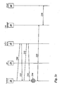
- Figures 3a to 3c show three different examples related to the routing of packets of an emergency call.
- a sequence of messages is transmitted between the terminal 10, the access point 20 of the LAN 3, a NAT server 22 associated with the access point 20, the DHCP server 30, the call manager 40 and the PSAP 60.
- Fig. 3a shows a message flow sequence related to a packet routing based on a DHCP method.
- a client asks - when requesting an IP address - for a particular DHCP option that will give the client the call manager's IP address.
- the terminal 10 sends a DHCP DISCOVER message 210.
- both devices have to be within the same IP network unless a DHCP relay is used. If both devices are not within the same IP network, a DHCP assistance device such as a DHCP relay unit or a DHCP helper unit may be used which relay and/or forward DHCP related messages to the network where the DHCP server is located.
- the DHCP DISCOVER message 210 sent by the terminal 10 reaches the DHCP server 30. This may be achieved by sending the DHCP DISCOVER message 210 in broadcast if the terminal 10 and the DHCP server 30 are in the same network, e.g., VLAN, or via a DHCP helper.
- the terminal 10 requests an IP address from the DHCP server 30.
- the MAC address also known as LAN address, Ethernet ID or airport ID, is the hardware address of a network device which serves for unique identfication of the device in the network.
- the terminal 10 sends the DHCP DISCOVER message 210 as a network broadcast to all available DHCP servers. It is possible that several DHCP servers are located within the same IP subnetwork.
- the DHCP DISCOVER broadcast message 210 may carry as sender IP address 0.0.0.0 and may be addressed to the destination address 255.255.255.255, as the sending terminal 10 does not possess an IP address, yet, and directs the request to all reachable DHCP servers.
- the DHCP server 30 receives the DHCP DISCOVER message 210 and replies with a DHCP OFFER message 211 which comprises an offer of an IP address for the requesting terminal 10.
- the DHCP OFFER message 211 further comprises a server ID identifying the sending DHCP server 30 and an IP address and a port of the call manager 40. It is possible that the terminal 10 receives more than one offer message from different DHCP servers. Thus, the terminal may choose between the received offers. After selecting one of the one or more proposed offers, the terminal contacts, by means of a DHCP REQUEST message 212, the appropriate DHCP server 30 which is identified by means of the corresponding server ID. Preferably, the DHCP REQUEST message 212 is broadcast.
- the transmitted DHCP ACK message 213 comprises the IP address of the terminal 10, the IP address of the call manager 40 and a port on which the call manager 40 is contantly listening, and additional relevant data.
- the terminal 10 has its own IP address, the call manager's 40 IP address and the port the call manager 40 is listening on.
- the terminal 10 addresses the packets related to the emergency call with the destination address and port of the call manager 40 and sends the addressed packets to the call manager 40.
- An RTP flow 215 between the terminal 10 and the call manager 40 is established.
- the call manager 40 receives the packets related to the emergency call, initiates a call setup 216 to the relevant PSAP 60 and forwards the packets to the PSAP 60.
- Fig. 3b shows a message flow sequence related to a packet routing based on a destination NAT.
- a client can send packets to any destination address once he received an IP address.
- a NAT server 22 will modify this address into the one of the call manager 30.
- the steps 220 to 224 of Fig. 3b correspond to the steps 210 to 214 shown in Fig. 3a .
- the only difference with respect to the method illustrated in Fig. 3a is that the DHCP OFFER message 221 and the DHCP ACK message 223 do not comprise the IP address and the port of the call manager 40.
- the terminal 10 receives an IP address for joining the LAN 3 via another method than via DHCP.
- the terminal 10 retrieves its IP address, only.
- the terminal 10 addresses the packets related to the emergency call with any IP address as destination address and sends the addressed packets to the NAT server 22 associated with the AP 20.
- An RTP flow 225 between the terminal 10 and the NAT server 22 is established.
- the NAT server 22 receives the packets from the terminal 10 and translates the destination address to the IP address of the call manager 40.
- An RTP flow 226 between the NAT server 22 and the call manager 40 is established.
- the call manager 40 receives the information related to the emergency call in packet form or stream form, initiates a call setup 227 to the relevant PSAP 60 and forwards the packets to the PSAP 60.
- Fig. 3c shows a message flow sequence related to a packet routing based on a multicast method.
- a client - once he received an IP address - sends packets to a well-known multicast address on a predefined port on which the call manager 40 is listening.
- the steps 230 to 234 of Fig. 3c correspond to the steps 210 to 214 shown in Fig. 3a .
- the only difference with respect to the method illustrated in Fig. 3a is that the DHCP OFFER message 231 and the DHCP ACK message 233 do not comprise the IP address and the port of the call manager 40.
- the terminal 10 receives an IP address for joining the LAN 3 via another method than via DHCP.
- the terminal 10 retrieves its IP address, only.
- the terminal 10 addresses the packets related to the emergency call with a multicast IP address as destination address and sends the addressed packets to the call manager 40.
- An RTP flow 235 between the terminal 10 and the call manager 40 is established.
- the call manager 40 receives the information (packet/stream form) related to the emergency call, initiates a call setup 236 to the relevant PSAP 60 and forwards the packets to the PSAP 60.
- Figure 4 shows a group 700 of authorized users of the WLAN 2 comprising the terminals 70 to 73.
- the group 700 of authorized users is able to access the LAN 3 with a non-emergency call by using a first SSID 7.
- the members of the group 700 are also members of an open group 800.
- the open group 800 both comprises the authorized users with the terminals 70 to 73 and the non-authorized users of the WLAN 2 with the terminals 10 to 13. Only the group 700 of authorized users is entitled to access the LAN 3 with a non-emergency call by using a first SSID 7.
- both the members of the group 700 and the members of the group 800 are enabled to access the LAN 3 with an emergency call by using an emergency SSID 8 since the group 800 is located in the coverage area of the access point 20.
- Any terminal of the group 700 or the group 800 may access the LAN 3 via the access point 20 using the emergency SSID 8, e.g., the terminal 10 or the terminal 71.
- any terminal in the coverage area of the access point 20 may access the LAN 3 in the case of an emergency by using the emergency SSID 8.
- the emergency SSID 8 In the case of a non-emergency call, only terminals of the authorized group 700 comprising authorized users of the WLAN 2 may access the LAN 3 via the access point 20. While calls associated with the emergency SSID 8 will be routed to the PSAP 60, a non-emergency call, e.g., originating from the terminal 70, may be routed to another communication partner 90 in a procedure as known from the prior art.
- the access control function 21 may - in addition to restricting access to the LAIN 3 to data packets from a terminal associated with an authorized SSID - apply additional rules to the arriving data packets. It is possible that each user sending data packets from a terminal associated with an emergency SSID to the LAN 2 may be allocated a limited bandwidth which is sufficient to set up the emergency call to the PSAP 60 but is not wide enough to establish other calls. This access control mechanism may work since an emergency call may be rather restricted concerning the amount of data.
- Figure 5 shows a network 400 for transmission of IP packets and two wireless access networks 401, 402 for providing access to the network 400.
- the corporate access network 401 is a corporate access network only accessible by authorized user terminals 701, 702, whereas the emergency access network 402 is accessible for emergency purposes by any mobile user terminal within the service area of the emergency access network 402, i.e., both by the authorized user terminals 701, 702 and guest user terminals 801 to 803.
- the authorized terminals 701, 702 may comprise encryption modules 7010, 7020 enabling the terminals 701, 702 to properly encrypt data packets before transmitting them to the access network 4012.
- Each access network 401, 402 broadcasts, by means of a sender, e.g., by means of an AP, a SSID specific to the respective access network.
- the corporate access network 401 broadcasts a corporate SSID associated to the corporate access network 401
- the emergency access network 402 broadcasts an emergency SSID associated to the emergency access network 401.
- the broadcast SSIDs can be received by any terminal in the coverage area of the access networks 401, 402.
- the corporate access network 401 comprises an access control function 4011, and similarly, the emergency access network 402 comprises an access control function 4021.
- the access control functions 4011, 4021 are implemented as stand-alone servers comprising access control rules stored in a memory module. Each of the access control functions 4011, 4021 filters arriving data packets before admitting them to the access networks 401, 402.
- Data packets from a terminal associated with the emergency SSID associated to the emergency access network 402 are granted access by the access control function 4021 to the emergency access network 402.
- the authorized user terminals 701, 702, only, may be able to properly encrypt data packets by means of the encryption modules 7010, 7020.
- Data packets arriving at the access control function 4011 must originate from a terminal associated with the corporate SSID associated to the corporate access network 401 and may be properly encrypted to be admitted to the access network 401.
- the access control function 4011 filters the arriving data packets and discards data packets which do not originate from the authorized user terminals.
- the access control function 4011 retrieves data relevant for the filtering and examination process from a data base 4012.
- the guest user terminal 801 has taken notice of the corporate SSID and uses the corporate SSID to access the corporate access network 401. It is possible that a network administrator of the corporate access network 401 configures a public corporate SSID that is set on an access point of the corporate access network 401 and broadcast to all wireless devices in range. Thus, the corporate SSID has been openly broadcast by the corporate access network 401 and the guest user terminal 801 has received the corporate SSID by picking up the broadcast corporate SSID.
- the guest user terminal 801 is associated with an eavesdropper who wants to use the communications services offered by the corporate access network 401 in an unauthorized manner.
- the network administrator of the corporate access network 401 has disabled the automatic SSID broadcast feature in an attempt to improve network security as the public broadcast of the corporate SSID may pose a security risk.
- the protection offered by the deactivation of a SSID broadcast may be easily circumvented by the eavesdropper as the SSID can be sniffed in plain text from a data packet sent by an authorized terminal 701, 702 to the corporate access network 401.
- the guest user terminal 801 has received the corporate SSID, associates with the corporate SSID and sends a data packet stream 301 to the corporate access network 401.
- the examination carried out by the access control function 4011 on the data packet stream 301 results in a rejection of the data packet stream 301.
- the authorized user terminal 701 comprising the encryption module 7010 sends data packets 1001 to the corporate access network 401 which both are from a terminal associated with the corporate SSID and are properly encrypted.
- the examination process at the access control function 4011 results in admission to the access network.
- the data packets 1002 originating from the other authorized user terminal 702 also are admitted to the corporate access network 401.
- the data packets 502 are admitted to the emergency access network 402.
- the guest user terminal 802 sends a data packet stream 501 related to the emergency SSID to the corporate access network 401 but is not admitted to the corporate access network 401 since the data packet stream 501 neither is from a terminal associated with the proper SSID nor is properly encrypted.
- the guest user terminal 802 associated with the emergency SSID sends a data packet stream 502 to the emergency access network 402
- the data packet stream 502 is admitted to the emergency access network 402 by the access control function 4021 since the data packets 503 are from a terminal associated with the emergency SSID.
- the access control function 4021 only admits data packets from a terminal associated with the emergency SSID.
- the data streams 1001 and 1002 are forwarded as data streams 601 and 602 to the network 400 and routed to a network element 4001, e.g., a router or a switch, which routes or switches the data streams 601 and 602 according to the IP destination addresses indicated in the data packets of the data streams 601 and 602.
- a network element 400 e.g., a router or a switch
- a VolP user agent of the authorized user terminal 701 correspondingly addresses the data packets 1001, 601 with the corresponding address, and the data packets stream 601 is routed by the network element 4001 to another network element 4002 which is responsible for the address.
- the establishment of a connection requires an exchange of signalling and control messages for proper routing and call establishment.
- the data packets 1002 are routed via the network element 4002 to another network element 4003. There is no pre-established routing, instead each next hop in the network 400 is determined by each network element individually for every data packet according to the indicated address of a data packet.
- PBX Private Branch Exchange
- the routing is executed on a pre-established connection without the need for any signalling and controlling traffic.
- the original destination address of the data packets admitted to the emergency access network 402 may be stripped off the data packets and substituted with a pre-set standard address associated with the emergency service, e.g., an IP address and port of the call manager 4001.
- a pre-set standard address associated with the emergency service e.g., an IP address and port of the call manager 4001.
- Figures 6a to 6d show four different examples related to the localization of a terminal initiating an emergency call.
- a sequence of messages is transmitted between the terminal 10, the access point 20 of the LAN 3, the DHCP server 30, a localization server 35, the call manager 40, and the PSAP 60.
- the localization server 35 hosts web services providing the transmission of localization information to the PSAP.
- Fig. 6a shows a message flow sequence related to the localization of the terminal 10 according to a first alternative.
- SOAP Simple Object Access Protocol
- BSSID Basic Service Set Identifier
- the BSSID is a unique identifier of an AP in a LAN.
- the IEEE 802.11-1999 Wireless LAN specification defines a BSSID as a MAC address identifying a station (STA) of an AP in infrastructure mode.
- STA station
- the BSSID uniquely identifies each AP, which is indispensable for distinguishing APs with identical SSID.
- the localization server 35 responds by a reply 511 which acts as an acknowledgment of the request 510. If the terminal 10 receives no reply within a certain period of time after sending the SOAP request message 510, the terminal 10 can re-send the SOAP request message 510.
- the call manager 40 starts to regularly poll the localization server 35 by sending a polling message 512 to the localization server 35.
- the polling message 512 triggers the localization server 35 to report to the call manager 40 any update information relating the localization information of the terminal 10.
- the localization server 35 always responds with localization information.
- the localization server 35 responds to the polling message 512 by sending a reply 513.
- the reply 513 comprises either update information regarding the location of the terminal or simply an indication that no update information is available.
- the call manager 40 will simply forward the retrieved localization information as message 514 to the PSAP 60 or will process the retrieved localization information and then send the processed localization information as message 514 to the PSAP 60.
- the localization server 35 may translate the AP BSSID of the localization information to geographic coordinates, e.g., by means of a data base comprising the BSSIDs and corresponding locations of the APs of the LAN.
- the call manager will then send the geographic coordinates to the PSAP 60 where assistance may be sent to the indicated geographic location.
- Fig. 6b shows a message flow sequence related to the localization of the terminal 10 according to a second alternative.
- the steps 520 to 521 correspond to the steps 510 to 511 described with reference to Fig. 6a .
- the corresponding description given above also applies to Fig. 6b .
- the localization server 35 After the localization server 35 has received the localization information or an update of the localization information from the terminal 10 and, preferably, has sent a reply 521 to the terminal 10, the localization server 35 pushes the localization information to the call manager 40 by means of message 522. In response to the message 522, the call manager 40 sends a reply message 523 for acknowledgment to the localization server 35.
- the call manager 40 will simply forward the retrieved localization information to the PSAP 60 as message 524 or will process the retrieved localization information and then send processed localization information as message 524 to the PSAP 60, as described above with reference to Fig. 6a .
- Fig. 6c shows a message flow sequence related to the localization of the terminal 10 according to a third alternative.
- the terminal 10 after association to an emergency SSID, sends a SOAP request message 530 via the AP 20 to the call manager 40.
- the SOAP request message 510 comprises localization information of the terminal 10, e.g., a BSSID of the AP 10 via which the terminal has access to the LAN.
- the call manager 40 responds by a reply 531 which acts as an acknowledgment of the request 530. If the terminal 10 receives no reply within a certain period of time after sending the SOAP request message 530, the terminal 10 can re-send the SOAP request message 530 to the call manager 40.
- the call manager 40 After the call manager 40 has received the localization information or an update of the localization information from the terminal 10 and, preferably, has sent a reply 531 to the terminal 10, the call manager 40 will simply forward the retrieved localization information as message 532 to the PSAP 60 or will process the retrieved localization information and then send the processed localization information as message 532 to the PSAP 60, as described above with reference to Fig. 6a .
- Fig. 6d shows a message flow sequence related to the localization of the terminal 10 according to a fourth alternative.
- the terminal 10 after association to an emergency SSID, sends a DHCP renew request 540 to the DHCP server 30.
- the DHCP renew request 540 comprises localization information of the terminal 10, e.g., a BSSID of the AP 10 via which the terminal has access to the LAN.
- the DHCP server 30 either sends a SOAP message 541 to the localization server 35 or sends a SOAP message 546 to the call manager 40.
- the localization information may be transmitted to the call manager 40 either by a, preferably regular, polling message 542 from the call manager and corresponding reply 543 from the localization server 35, as described above, or by pushing the localization information by means of a message 544 from the localization server 35 to the call manager 40 as soon as the localization server 35 has received the SOAP message 541.
- the call manager 40 may respond to the message 544 with a acknowledgment reply 545.
- the call manager 40 After the call manager 40 has received the localization information from the localization server 35, the call manager 40 will simply forward the retrieved localization information as message 547 to the PSAP 60 or will process the retrieved localization information and then send the processed localization information as message 547 to the PSAP 60, as described above with reference to Fig. 6a .
- the call manager 40 will again forward the retrieved original localization information or a processed localization information as message 547 to the PSAP 60.
Landscapes
- Engineering & Computer Science (AREA)
- Computer Networks & Wireless Communication (AREA)
- Signal Processing (AREA)
- Environmental & Geological Engineering (AREA)
- Health & Medical Sciences (AREA)
- Emergency Management (AREA)
- Business, Economics & Management (AREA)
- Public Health (AREA)
- Computer Security & Cryptography (AREA)
- Mobile Radio Communication Systems (AREA)
- Telephonic Communication Services (AREA)
- Data Exchanges In Wide-Area Networks (AREA)
- Alarm Systems (AREA)
Priority Applications (9)
| Application Number | Priority Date | Filing Date | Title |
|---|---|---|---|
| AT06360015T ATE551799T1 (de) | 2006-04-29 | 2006-04-29 | Verfahren zu einem notfälligen gastzugang zu einem drahtlosen netzwerk |
| ES06360015T ES2381392T3 (es) | 2006-04-29 | 2006-04-29 | Procedimiento de provisión a un terminal visitador de un acceso de emergencia sobre una WLAN |
| EP06360015A EP1850532B1 (en) | 2006-04-29 | 2006-04-29 | Method of providing a guest terminal with emergency access over a WLAN |
| PL06360015T PL1850532T3 (pl) | 2006-04-29 | 2006-04-29 | Sposób zapewnienia gościnnemu terminalowi alarmowego dostępu za pośrednictwem sieci WLAN |
| JP2009508276A JP4913209B2 (ja) | 2006-04-29 | 2007-03-26 | ゲスト端末装置にwlanへの緊急アクセスを提供する方法 |
| PCT/EP2007/052843 WO2007124987A1 (en) | 2006-04-29 | 2007-03-26 | Method of providing a guest terminal with emergency access to a wlan |
| KR1020087026559A KR101226042B1 (ko) | 2006-04-29 | 2007-03-26 | Wlan으로의 긴급 액세스를 게스트 단말에 제공하는 방법 |
| US11/697,288 US7877785B2 (en) | 2006-04-29 | 2007-04-05 | Method of providing a guest terminal with emergency access to a WLAN |
| CN2007101077689A CN101064655B (zh) | 2006-04-29 | 2007-04-29 | 为客户终端提供紧急接入wlan的方法 |
Applications Claiming Priority (1)
| Application Number | Priority Date | Filing Date | Title |
|---|---|---|---|
| EP06360015A EP1850532B1 (en) | 2006-04-29 | 2006-04-29 | Method of providing a guest terminal with emergency access over a WLAN |
Publications (2)
| Publication Number | Publication Date |
|---|---|
| EP1850532A1 EP1850532A1 (en) | 2007-10-31 |
| EP1850532B1 true EP1850532B1 (en) | 2012-03-28 |
Family
ID=36780758
Family Applications (1)
| Application Number | Title | Priority Date | Filing Date |
|---|---|---|---|
| EP06360015A Active EP1850532B1 (en) | 2006-04-29 | 2006-04-29 | Method of providing a guest terminal with emergency access over a WLAN |
Country Status (9)
| Country | Link |
|---|---|
| US (1) | US7877785B2 (zh) |
| EP (1) | EP1850532B1 (zh) |
| JP (1) | JP4913209B2 (zh) |
| KR (1) | KR101226042B1 (zh) |
| CN (1) | CN101064655B (zh) |
| AT (1) | ATE551799T1 (zh) |
| ES (1) | ES2381392T3 (zh) |
| PL (1) | PL1850532T3 (zh) |
| WO (1) | WO2007124987A1 (zh) |
Families Citing this family (95)
| Publication number | Priority date | Publication date | Assignee | Title |
|---|---|---|---|---|
| US8682279B2 (en) * | 2004-05-07 | 2014-03-25 | Interdigital Technology Corporation | Supporting emergency calls on a wireless local area network |
| CN101296509B (zh) * | 2007-04-28 | 2012-12-12 | 华为技术有限公司 | 紧急通信业务实现方法、系统及其相关设备 |
| US20080281697A1 (en) | 2007-05-11 | 2008-11-13 | Verizon Services Organization Inc. | Systems and methods for using video services records to provide targeted marketing services |
| JP2009219076A (ja) * | 2008-03-13 | 2009-09-24 | Nec Corp | Ip電話システムにおけるゲートウェイルータおよび緊急呼の優先制御方法 |
| DE102008017136B4 (de) * | 2008-04-03 | 2013-01-31 | Siemens Aktiengesellschaft | Vorrichtung zum Bereitstellen eines Dienstes für ein mobiles Endgerät über eine WLAN-Verbindung |
| US9148769B2 (en) | 2008-05-07 | 2015-09-29 | Qualcomm Incorporated | System, apparatus and method to enable mobile stations to identify calls based on predetermined values set in a call header |
| EP2335176A1 (en) * | 2008-08-20 | 2011-06-22 | Wherepro, LLC | Data packet generator for generating passcodes |
| US8732813B2 (en) * | 2008-11-05 | 2014-05-20 | Apriva, Llc | Method and system for securing data from an external network to a non point of sale device |
| US20100114723A1 (en) * | 2008-11-05 | 2010-05-06 | Appsware Wireless, Llc | Method and system for providing a point of sale network within a lan |
| US20100115599A1 (en) * | 2008-11-05 | 2010-05-06 | Appsware Wireless, Llc | Method and system for securing data from a point of sale device over an external network |
| US8966610B2 (en) * | 2008-11-05 | 2015-02-24 | Apriva, Llc | Method and system for securing data from a non-point of sale device over an external network |
| US20100115127A1 (en) * | 2008-11-05 | 2010-05-06 | Appsware Wireless, Llc | Method and system for securing data from a non-point of sale device over a lan |
| US20100115624A1 (en) * | 2008-11-05 | 2010-05-06 | Appsware Wireless, Llc | Method and system for securing data from a point of sale device over a lan |
| US20100115600A1 (en) * | 2008-11-05 | 2010-05-06 | Appsware Wireless, Llc | Method and system for securing data from an external network to a point of sale device |
| JP5545757B2 (ja) * | 2008-12-26 | 2014-07-09 | 日本電気株式会社 | 通信システム、フェムト基地局、コール状態制御サーバ、ホーム加入者サーバ、通信方法およびプログラム |
| CN101730038A (zh) * | 2009-04-29 | 2010-06-09 | 中兴通讯股份有限公司 | 紧急业务的实现方法及家用基站 |
| CN101931954B (zh) * | 2009-06-22 | 2013-02-27 | 南京中兴软件有限责任公司 | 一种基于业务区分改进无线局域网中实时业务QoS的方法 |
| CN102118372B (zh) * | 2009-12-31 | 2013-07-10 | 深圳市多尼卡电子技术有限公司 | 提供非实时互联网服务的系统和方法 |
| US8955054B2 (en) * | 2010-01-06 | 2015-02-10 | Qualcomm Incorporated | Method and apparatus for providing simultaneous support for multiple master keys at an access point in a wireless communication system |
| EP2373075A1 (en) | 2010-03-30 | 2011-10-05 | British Telecommunications public limited company | System and method for WLAN traffic monitoring |
| EP2405678A1 (en) | 2010-03-30 | 2012-01-11 | British Telecommunications public limited company | System and method for roaming WLAN authentication |
| US9689988B1 (en) * | 2010-06-03 | 2017-06-27 | 8X8, Inc. | Systems, methods, devices and arrangements for emergency call services and emergency broadcasts |
| ES2750031T3 (es) * | 2010-09-16 | 2020-03-24 | Nokia Technologies Oy | Creación dinámica de cuentas con red de zona con cobertura inalámbrica asegurada |
| CN102457907B (zh) * | 2010-10-25 | 2015-07-29 | 上海贝尔股份有限公司 | 集中式无线局域网中识别客户端类型的方法和装置 |
| US9763140B2 (en) | 2010-11-02 | 2017-09-12 | Cisco Technology, Inc. | Resource reservation on networks comprising wireless and wired segments |
| JP2012182743A (ja) * | 2011-03-02 | 2012-09-20 | Toshiba Tec Corp | 電子機器、通信システムおよびプログラム |
| JP5655672B2 (ja) * | 2011-03-31 | 2015-01-21 | 富士通株式会社 | プログラム、情報通信機器および連携方法 |
| US8869259B1 (en) * | 2011-05-19 | 2014-10-21 | Zscaler, Inc. | Cloud based inspection of secure content avoiding man-in-the-middle attacks |
| KR101453521B1 (ko) | 2011-05-20 | 2014-10-24 | 주식회사 케이티 | 무선 액세스 포인트 장치 및 비인가 무선 랜 노드 탐지 방법 |
| WO2012161386A1 (ko) * | 2011-05-20 | 2012-11-29 | 주식회사 케이티 | 무선 액세스 포인트 장치 및 비인가 무선 랜 노드 탐지 방법 |
| US8769023B2 (en) * | 2011-08-03 | 2014-07-01 | Juniper Networks, Inc. | Disaster response system |
| US8856290B2 (en) * | 2011-10-24 | 2014-10-07 | General Instrument Corporation | Method and apparatus for exchanging configuration information in a wireless local area network |
| MY161907A (en) * | 2011-12-23 | 2017-05-15 | Telekom Malaysia Berhad | System and method for providing multiple identifiers in a single access point |
| KR101918040B1 (ko) * | 2012-02-20 | 2019-01-29 | 삼성전자주식회사 | 스크린 미러링 방법 및 그 장치 |
| CN103379586B (zh) * | 2012-04-24 | 2018-09-28 | 华为终端(东莞)有限公司 | 一种发现接入点的方法及站点、接入点 |
| CN102821355A (zh) * | 2012-05-15 | 2012-12-12 | 扬州易游物联网络科技有限公司 | 一种简便的利用无线局域网进行用户定位的方法 |
| US10129751B2 (en) | 2012-05-25 | 2018-11-13 | Comcast Cable Communications, Llc | Wireless gateway supporting public and private networks |
| CN103517383B (zh) * | 2012-06-18 | 2017-04-12 | 华为终端有限公司 | 移动终端接入家庭网络的方法和设备 |
| JP5912913B2 (ja) * | 2012-06-26 | 2016-04-27 | アルパイン株式会社 | 車載機器 |
| US9565622B2 (en) * | 2012-07-05 | 2017-02-07 | Qualcomm Incorporated | Detecting services provided by a wireless node before device discovery and connection establishment |
| US10708121B2 (en) * | 2012-11-05 | 2020-07-07 | Comcast Cable Communications, Llc | Intelligent network |
| EP2934027A4 (en) * | 2012-12-13 | 2015-12-23 | Fujitsu Ltd | WIRELESS COMMUNICATION SYSTEM |
| US8930044B1 (en) | 2012-12-28 | 2015-01-06 | Google Inc. | Multi-part navigation process by an unmanned aerial vehicle for navigating to a medical situatiion |
| US8983682B1 (en) | 2012-12-28 | 2015-03-17 | Google Inc. | Unlocking mobile-device and/or unmanned aerial vehicle capability in an emergency situation |
| US9051043B1 (en) | 2012-12-28 | 2015-06-09 | Google Inc. | Providing emergency medical services using unmanned aerial vehicles |
| US8909391B1 (en) | 2012-12-28 | 2014-12-09 | Google Inc. | Responsive navigation of an unmanned aerial vehicle to a remedial facility |
| US8948935B1 (en) | 2013-01-02 | 2015-02-03 | Google Inc. | Providing a medical support device via an unmanned aerial vehicle |
| GB2511313A (en) | 2013-02-27 | 2014-09-03 | Sony Corp | A relay device, method and computer program |
| EP2824973A1 (en) * | 2013-07-09 | 2015-01-14 | Orange | Network architecture enabling a mobile terminal to roam into a wireless local area network |
| CN104427587A (zh) * | 2013-08-23 | 2015-03-18 | 联想移动通信科技有限公司 | 一种无线局域网接入点的连接方法及移动设备 |
| US9386148B2 (en) | 2013-09-23 | 2016-07-05 | Ooma, Inc. | Identifying and filtering incoming telephone calls to enhance privacy |
| US9686819B2 (en) | 2013-09-24 | 2017-06-20 | Xiaomi Inc. | Methods, devices and systems for router access control |
| CN103501482A (zh) * | 2013-09-26 | 2014-01-08 | 小米科技有限责任公司 | 网络接入方法、装置及终端 |
| DE102014202758A1 (de) * | 2014-02-14 | 2015-08-20 | Fraunhofer-Gesellschaft zur Förderung der angewandten Forschung e.V. | Verfahren, Vorrichtung und Drahtlosnetzwerkumgebung zum Austausch von Daten |
| JP6330445B2 (ja) * | 2014-04-17 | 2018-05-30 | 株式会社バッファロー | 通信システム |
| US10239638B1 (en) | 2014-05-10 | 2019-03-26 | Wing Aviation Llc | Home station for unmanned aerial vehicle |
| US10769931B2 (en) | 2014-05-20 | 2020-09-08 | Ooma, Inc. | Network jamming detection and remediation |
| US9633547B2 (en) | 2014-05-20 | 2017-04-25 | Ooma, Inc. | Security monitoring and control |
| US10553098B2 (en) * | 2014-05-20 | 2020-02-04 | Ooma, Inc. | Appliance device integration with alarm systems |
| US11330100B2 (en) | 2014-07-09 | 2022-05-10 | Ooma, Inc. | Server based intelligent personal assistant services |
| CN105451188B (zh) * | 2014-08-08 | 2018-11-16 | 阿里巴巴集团控股有限公司 | 实现信息推送的方法、服务器、共享者客户端、第三方客户端 |
| JP5915712B2 (ja) * | 2014-09-30 | 2016-05-11 | 富士通株式会社 | 制御プログラム、制御装置、および、制御方法 |
| US9923814B2 (en) * | 2015-02-17 | 2018-03-20 | Huawei Technologies Co., Ltd. | Media access control address resolution using internet protocol addresses |
| US20160295386A1 (en) * | 2015-04-03 | 2016-10-06 | Qualcomm Incorporated | Techniques to support emergency services |
| US11171875B2 (en) | 2015-05-08 | 2021-11-09 | Ooma, Inc. | Systems and methods of communications network failure detection and remediation utilizing link probes |
| US10009286B2 (en) | 2015-05-08 | 2018-06-26 | Ooma, Inc. | Communications hub |
| US10771396B2 (en) | 2015-05-08 | 2020-09-08 | Ooma, Inc. | Communications network failure detection and remediation |
| US10911368B2 (en) | 2015-05-08 | 2021-02-02 | Ooma, Inc. | Gateway address spoofing for alternate network utilization |
| JP6627314B2 (ja) | 2015-08-03 | 2020-01-08 | 株式会社リコー | 通信システム、通信方法、通信装置およびプログラム |
| US9832791B2 (en) | 2015-08-04 | 2017-11-28 | Network Performance Research Group Llc | Method and apparatus for use of simultaneous multiple channels in the dynamic frequency selection band in wireless networks |
| US10104665B2 (en) | 2015-08-10 | 2018-10-16 | Network Performance Research Group Llc | Method and apparatus for providing dynamic frequency selection spectrum access in peer-to-peer wireless networks |
| US9439197B1 (en) | 2015-08-10 | 2016-09-06 | Planetary Network Technologies, Inc. | Method and apparatus for directed adaptive control of dynamic channel selection in wireless networks |
| US20170048728A1 (en) * | 2015-08-10 | 2017-02-16 | Network Performance Research Group Llc | Method and apparatus for directed adaptive control of access point-to-client interaction in wireless networks |
| US9924518B2 (en) | 2015-08-10 | 2018-03-20 | Network Performance Research Group Llc | Method and apparatus for dynamic channel selection device |
| US9807625B2 (en) | 2015-08-10 | 2017-10-31 | Network Performance Research Group Llc | Method and apparatus for using time shifted analysis based on gathering non-encrypted information from packets |
| CN105263099B (zh) * | 2015-08-28 | 2018-10-12 | 小米科技有限责任公司 | 发送位置信息的方法和装置 |
| FR3041842A1 (fr) * | 2015-09-30 | 2017-03-31 | Orange | Systeme de restauration de services fournis par une passerelle residentielle |
| US10368247B2 (en) | 2015-11-25 | 2019-07-30 | Network Performance Research Group Llc | Cloud DFS super master detector location systems and methods |
| US9839038B2 (en) | 2015-11-25 | 2017-12-05 | Network Performance Research Group Llc | System, method, and apparatus for setting a regulatory operating mode of a device |
| US9930670B2 (en) | 2015-11-25 | 2018-03-27 | Network Performance Research Group Llc | System, method, and apparatus for setting device geolocation via location proxies |
| CN108141758B (zh) * | 2015-12-09 | 2021-12-03 | 惠普发展公司有限责任合伙企业 | 无连接的数据传输 |
| WO2018017480A1 (en) * | 2016-07-20 | 2018-01-25 | Level 3 Communications, Llc | Dynamic service provisioning system and method |
| CN106130866A (zh) * | 2016-08-01 | 2016-11-16 | 浪潮(苏州)金融技术服务有限公司 | 一种基于udp实现的局域网设备自主接入方法 |
| US10604252B2 (en) | 2016-11-22 | 2020-03-31 | Wing Aviation Llc | Landing and payload loading structures |
| US9867217B1 (en) * | 2016-12-30 | 2018-01-09 | T-Mobile Usa, Inc. | Emergency call setup in wireless networks |
| PT3379790T (pt) * | 2017-03-22 | 2020-01-15 | Deutsche Telekom Ag | Método para um tratamento melhorado de uma chamada de emergência comutada por pacotes dentro de uma rede de telecomunicações e/ou para um tratamento melhorado da informação do serviço de emergência local por um equipamento de utilizador, sistema, equipamento de utilizador e programa |
| US10691142B2 (en) | 2017-12-21 | 2020-06-23 | Wing Aviation Llc | Anticipatory dispatch of UAVs to pre-staging locations |
| PL3503599T3 (pl) * | 2017-12-22 | 2020-07-27 | Deutsche Telekom Ag | Alarmowy plaster sieci i sposób oraz jednostka dostępu do sieci do przetwarzania komunikacji alarmowej w sieci komunikacyjnej z komutacją pakietów |
| CN109729151B (zh) * | 2018-12-06 | 2022-05-03 | 浙江大学宁波理工学院 | 一种车载终端数据传输系统及方法 |
| CN112040424B (zh) * | 2019-06-04 | 2022-04-05 | 成都鼎桥通信技术有限公司 | 一种紧急抢占话权的方法和系统 |
| CN111586145B (zh) * | 2020-04-30 | 2023-06-30 | 深圳市元征科技股份有限公司 | 一种车辆诊断方法、系统及电子设备和存储介质 |
| US11667402B2 (en) | 2020-09-08 | 2023-06-06 | Wing Aviation Llc | Landing pad with charging and loading functionality for unmanned aerial vehicle |
| CN113747413B (zh) * | 2021-11-04 | 2022-02-22 | 北京百瑞互联技术有限公司 | 多网络多模车载紧急呼叫方法、系统及介质 |
| US20230156448A1 (en) * | 2021-11-12 | 2023-05-18 | Charter Communications Operating, Llc | Method and System for Supporting Emergency Voice Services Over Wireless Local Area Network (WLAN) Using Dynamic SSID Deployment |
| US11876866B2 (en) | 2021-11-29 | 2024-01-16 | Industrial Technology Research Institute | Method for assisting unregistered user device to access end-to-end call service of private network and communication system |
Family Cites Families (15)
| Publication number | Priority date | Publication date | Assignee | Title |
|---|---|---|---|---|
| US6714536B1 (en) | 1998-07-21 | 2004-03-30 | Eric M. Dowling | Method and apparatus for cosocket telephony |
| US6950628B1 (en) | 2002-08-02 | 2005-09-27 | Cisco Technology, Inc. | Method for grouping 802.11 stations into authorized service sets to differentiate network access and services |
| US7835317B2 (en) | 2002-10-08 | 2010-11-16 | Nokia Corporation | Network selection in a WLAN |
| US7369859B2 (en) | 2003-10-17 | 2008-05-06 | Kineto Wireless, Inc. | Method and system for determining the location of an unlicensed mobile access subscriber |
| US7885644B2 (en) * | 2002-10-18 | 2011-02-08 | Kineto Wireless, Inc. | Method and system of providing landline equivalent location information over an integrated communication system |
| CN1802812A (zh) * | 2003-01-09 | 2006-07-12 | 汤姆森许可贸易公司 | 对多个接入点进行联合的方法和设备 |
| US20040181692A1 (en) | 2003-01-13 | 2004-09-16 | Johanna Wild | Method and apparatus for providing network service information to a mobile station by a wireless local area network |
| US7177399B2 (en) | 2004-02-27 | 2007-02-13 | Nortel Network Limited | Determining the geographical location from which an emergency call originates in a packet-based communications network |
| KR100842548B1 (ko) * | 2004-03-05 | 2008-07-01 | 삼성전자주식회사 | 긴급 호출 시스템 및 그 제어 방법 |
| US8145182B2 (en) * | 2004-05-07 | 2012-03-27 | Interdigital Technology Corporation | Supporting emergency calls on a wireless local area network |
| US20060068799A1 (en) | 2004-09-27 | 2006-03-30 | T-Mobile, Usa, Inc. | Open-host wireless access system |
| JP2006101421A (ja) * | 2004-09-30 | 2006-04-13 | Toshiba Corp | 映像信号処理回路 |
| US7433673B1 (en) * | 2004-12-17 | 2008-10-07 | Sprint Spectrum L.P. | Method and system for providing location information for a wireless local area network (WLAN) |
| US7496182B2 (en) * | 2005-04-15 | 2009-02-24 | Verizon Business Global Llc | Handling emergency service calls originating from internet telephony |
| US20060274729A1 (en) * | 2005-06-03 | 2006-12-07 | Michael Self | Apparatus and method for connecting a voice over IP telephone subscriber to the 911 emergency network |
-
2006
- 2006-04-29 AT AT06360015T patent/ATE551799T1/de active
- 2006-04-29 ES ES06360015T patent/ES2381392T3/es active Active
- 2006-04-29 EP EP06360015A patent/EP1850532B1/en active Active
- 2006-04-29 PL PL06360015T patent/PL1850532T3/pl unknown
-
2007
- 2007-03-26 WO PCT/EP2007/052843 patent/WO2007124987A1/en active Application Filing
- 2007-03-26 JP JP2009508276A patent/JP4913209B2/ja active Active
- 2007-03-26 KR KR1020087026559A patent/KR101226042B1/ko active IP Right Grant
- 2007-04-05 US US11/697,288 patent/US7877785B2/en active Active
- 2007-04-29 CN CN2007101077689A patent/CN101064655B/zh not_active Expired - Fee Related
Also Published As
| Publication number | Publication date |
|---|---|
| ATE551799T1 (de) | 2012-04-15 |
| WO2007124987A1 (en) | 2007-11-08 |
| ES2381392T3 (es) | 2012-05-25 |
| US7877785B2 (en) | 2011-01-25 |
| EP1850532A1 (en) | 2007-10-31 |
| KR101226042B1 (ko) | 2013-01-24 |
| JP4913209B2 (ja) | 2012-04-11 |
| CN101064655A (zh) | 2007-10-31 |
| US20080016556A1 (en) | 2008-01-17 |
| PL1850532T3 (pl) | 2012-10-31 |
| KR20090008302A (ko) | 2009-01-21 |
| CN101064655B (zh) | 2013-04-24 |
| JP2009535948A (ja) | 2009-10-01 |
Similar Documents
| Publication | Publication Date | Title |
|---|---|---|
| EP1850532B1 (en) | Method of providing a guest terminal with emergency access over a WLAN | |
| KR101258312B1 (ko) | 무선 근거리 통신 네트워크 상에서의 비상 콜을 지원하는 방법 | |
| US9125058B2 (en) | Method and system for selecting VPN connections in response to wireless network identifiers | |
| JP6926340B2 (ja) | 緊急ネットワークスライス及びパケット交換通信ネットワークにおいて緊急通信を処理する方法 | |
| US7298702B1 (en) | Method and system for providing remote telephone service via a wireless local area network | |
| TW201123824A (en) | Method and apparatus for supporting an emergency call in a wireless metropolitan area network | |
| WO2007055897A2 (en) | Method and system for supporting an emergency call | |
| US20230156448A1 (en) | Method and System for Supporting Emergency Voice Services Over Wireless Local Area Network (WLAN) Using Dynamic SSID Deployment | |
| WO2003077477A1 (en) | A method and system for controlling and filtering traffic in a wireless network |
Legal Events
| Date | Code | Title | Description |
|---|---|---|---|
| PUAI | Public reference made under article 153(3) epc to a published international application that has entered the european phase |
Free format text: ORIGINAL CODE: 0009012 |
|
| AK | Designated contracting states |
Kind code of ref document: A1 Designated state(s): AT BE BG CH CY CZ DE DK EE ES FI FR GB GR HU IE IS IT LI LT LU LV MC NL PL PT RO SE SI SK TR |
|
| AX | Request for extension of the european patent |
Extension state: AL BA HR MK YU |
|
| 17P | Request for examination filed |
Effective date: 20080415 |
|
| 17Q | First examination report despatched |
Effective date: 20080516 |
|
| AKX | Designation fees paid |
Designated state(s): AT BE BG CH CY CZ DE DK EE ES FI FR GB GR HU IE IS IT LI LT LU LV MC NL PL PT RO SE SI SK TR |
|
| GRAP | Despatch of communication of intention to grant a patent |
Free format text: ORIGINAL CODE: EPIDOSNIGR1 |
|
| GRAS | Grant fee paid |
Free format text: ORIGINAL CODE: EPIDOSNIGR3 |
|
| RAP1 | Party data changed (applicant data changed or rights of an application transferred) |
Owner name: ALCATEL LUCENT |
|
| GRAA | (expected) grant |
Free format text: ORIGINAL CODE: 0009210 |
|
| AK | Designated contracting states |
Kind code of ref document: B1 Designated state(s): AT BE BG CH CY CZ DE DK EE ES FI FR GB GR HU IE IS IT LI LT LU LV MC NL PL PT RO SE SI SK TR |
|
| REG | Reference to a national code |
Ref country code: GB Ref legal event code: FG4D |
|
| REG | Reference to a national code |
Ref country code: CH Ref legal event code: EP |
|
| REG | Reference to a national code |
Ref country code: AT Ref legal event code: REF Ref document number: 551799 Country of ref document: AT Kind code of ref document: T Effective date: 20120415 |
|
| REG | Reference to a national code |
Ref country code: IE Ref legal event code: FG4D |
|
| REG | Reference to a national code |
Ref country code: NL Ref legal event code: T3 |
|
| REG | Reference to a national code |
Ref country code: DE Ref legal event code: R096 Ref document number: 602006028437 Country of ref document: DE Effective date: 20120524 |
|
| REG | Reference to a national code |
Ref country code: ES Ref legal event code: FG2A Ref document number: 2381392 Country of ref document: ES Kind code of ref document: T3 Effective date: 20120525 |
|
| PG25 | Lapsed in a contracting state [announced via postgrant information from national office to epo] |
Ref country code: LT Free format text: LAPSE BECAUSE OF FAILURE TO SUBMIT A TRANSLATION OF THE DESCRIPTION OR TO PAY THE FEE WITHIN THE PRESCRIBED TIME-LIMIT Effective date: 20120328 |
|
| LTIE | Lt: invalidation of european patent or patent extension |
Effective date: 20120328 |
|
| PG25 | Lapsed in a contracting state [announced via postgrant information from national office to epo] |
Ref country code: FI Free format text: LAPSE BECAUSE OF FAILURE TO SUBMIT A TRANSLATION OF THE DESCRIPTION OR TO PAY THE FEE WITHIN THE PRESCRIBED TIME-LIMIT Effective date: 20120328 Ref country code: GR Free format text: LAPSE BECAUSE OF FAILURE TO SUBMIT A TRANSLATION OF THE DESCRIPTION OR TO PAY THE FEE WITHIN THE PRESCRIBED TIME-LIMIT Effective date: 20120629 Ref country code: LV Free format text: LAPSE BECAUSE OF FAILURE TO SUBMIT A TRANSLATION OF THE DESCRIPTION OR TO PAY THE FEE WITHIN THE PRESCRIBED TIME-LIMIT Effective date: 20120328 |
|
| REG | Reference to a national code |
Ref country code: AT Ref legal event code: MK05 Ref document number: 551799 Country of ref document: AT Kind code of ref document: T Effective date: 20120328 |
|
| PG25 | Lapsed in a contracting state [announced via postgrant information from national office to epo] |
Ref country code: CY Free format text: LAPSE BECAUSE OF FAILURE TO SUBMIT A TRANSLATION OF THE DESCRIPTION OR TO PAY THE FEE WITHIN THE PRESCRIBED TIME-LIMIT Effective date: 20120328 |
|
| PG25 | Lapsed in a contracting state [announced via postgrant information from national office to epo] |
Ref country code: BE Free format text: LAPSE BECAUSE OF FAILURE TO SUBMIT A TRANSLATION OF THE DESCRIPTION OR TO PAY THE FEE WITHIN THE PRESCRIBED TIME-LIMIT Effective date: 20120328 Ref country code: EE Free format text: LAPSE BECAUSE OF FAILURE TO SUBMIT A TRANSLATION OF THE DESCRIPTION OR TO PAY THE FEE WITHIN THE PRESCRIBED TIME-LIMIT Effective date: 20120328 Ref country code: CZ Free format text: LAPSE BECAUSE OF FAILURE TO SUBMIT A TRANSLATION OF THE DESCRIPTION OR TO PAY THE FEE WITHIN THE PRESCRIBED TIME-LIMIT Effective date: 20120328 Ref country code: IS Free format text: LAPSE BECAUSE OF FAILURE TO SUBMIT A TRANSLATION OF THE DESCRIPTION OR TO PAY THE FEE WITHIN THE PRESCRIBED TIME-LIMIT Effective date: 20120728 Ref country code: SE Free format text: LAPSE BECAUSE OF FAILURE TO SUBMIT A TRANSLATION OF THE DESCRIPTION OR TO PAY THE FEE WITHIN THE PRESCRIBED TIME-LIMIT Effective date: 20120328 Ref country code: RO Free format text: LAPSE BECAUSE OF FAILURE TO SUBMIT A TRANSLATION OF THE DESCRIPTION OR TO PAY THE FEE WITHIN THE PRESCRIBED TIME-LIMIT Effective date: 20120328 Ref country code: SI Free format text: LAPSE BECAUSE OF FAILURE TO SUBMIT A TRANSLATION OF THE DESCRIPTION OR TO PAY THE FEE WITHIN THE PRESCRIBED TIME-LIMIT Effective date: 20120328 |
|
| REG | Reference to a national code |
Ref country code: PL Ref legal event code: T3 |
|
| PG25 | Lapsed in a contracting state [announced via postgrant information from national office to epo] |
Ref country code: SK Free format text: LAPSE BECAUSE OF FAILURE TO SUBMIT A TRANSLATION OF THE DESCRIPTION OR TO PAY THE FEE WITHIN THE PRESCRIBED TIME-LIMIT Effective date: 20120328 Ref country code: PT Free format text: LAPSE BECAUSE OF FAILURE TO SUBMIT A TRANSLATION OF THE DESCRIPTION OR TO PAY THE FEE WITHIN THE PRESCRIBED TIME-LIMIT Effective date: 20120730 Ref country code: MC Free format text: LAPSE BECAUSE OF NON-PAYMENT OF DUE FEES Effective date: 20120430 |
|
| REG | Reference to a national code |
Ref country code: CH Ref legal event code: PL |
|
| PG25 | Lapsed in a contracting state [announced via postgrant information from national office to epo] |
Ref country code: LI Free format text: LAPSE BECAUSE OF NON-PAYMENT OF DUE FEES Effective date: 20120430 Ref country code: DK Free format text: LAPSE BECAUSE OF FAILURE TO SUBMIT A TRANSLATION OF THE DESCRIPTION OR TO PAY THE FEE WITHIN THE PRESCRIBED TIME-LIMIT Effective date: 20120328 Ref country code: AT Free format text: LAPSE BECAUSE OF FAILURE TO SUBMIT A TRANSLATION OF THE DESCRIPTION OR TO PAY THE FEE WITHIN THE PRESCRIBED TIME-LIMIT Effective date: 20120328 Ref country code: CH Free format text: LAPSE BECAUSE OF NON-PAYMENT OF DUE FEES Effective date: 20120430 |
|
| PLBE | No opposition filed within time limit |
Free format text: ORIGINAL CODE: 0009261 |
|
| STAA | Information on the status of an ep patent application or granted ep patent |
Free format text: STATUS: NO OPPOSITION FILED WITHIN TIME LIMIT |
|
| 26N | No opposition filed |
Effective date: 20130103 |
|
| REG | Reference to a national code |
Ref country code: DE Ref legal event code: R097 Ref document number: 602006028437 Country of ref document: DE Effective date: 20130103 |
|
| PG25 | Lapsed in a contracting state [announced via postgrant information from national office to epo] |
Ref country code: IE Free format text: LAPSE BECAUSE OF NON-PAYMENT OF DUE FEES Effective date: 20120429 |
|
| PG25 | Lapsed in a contracting state [announced via postgrant information from national office to epo] |
Ref country code: BG Free format text: LAPSE BECAUSE OF FAILURE TO SUBMIT A TRANSLATION OF THE DESCRIPTION OR TO PAY THE FEE WITHIN THE PRESCRIBED TIME-LIMIT Effective date: 20120628 |
|
| REG | Reference to a national code |
Ref country code: GB Ref legal event code: 732E Free format text: REGISTERED BETWEEN 20130926 AND 20131002 |
|
| REG | Reference to a national code |
Ref country code: FR Ref legal event code: GC Effective date: 20131018 |
|
| PG25 | Lapsed in a contracting state [announced via postgrant information from national office to epo] |
Ref country code: TR Free format text: LAPSE BECAUSE OF FAILURE TO SUBMIT A TRANSLATION OF THE DESCRIPTION OR TO PAY THE FEE WITHIN THE PRESCRIBED TIME-LIMIT Effective date: 20120328 |
|
| PG25 | Lapsed in a contracting state [announced via postgrant information from national office to epo] |
Ref country code: LU Free format text: LAPSE BECAUSE OF NON-PAYMENT OF DUE FEES Effective date: 20120429 |
|
| PG25 | Lapsed in a contracting state [announced via postgrant information from national office to epo] |
Ref country code: HU Free format text: LAPSE BECAUSE OF FAILURE TO SUBMIT A TRANSLATION OF THE DESCRIPTION OR TO PAY THE FEE WITHIN THE PRESCRIBED TIME-LIMIT Effective date: 20060429 |
|
| REG | Reference to a national code |
Ref country code: FR Ref legal event code: RG Effective date: 20141016 |
|
| REG | Reference to a national code |
Ref country code: FR Ref legal event code: PLFP Year of fee payment: 10 |
|
| REG | Reference to a national code |
Ref country code: FR Ref legal event code: PLFP Year of fee payment: 11 |
|
| REG | Reference to a national code |
Ref country code: FR Ref legal event code: PLFP Year of fee payment: 12 |
|
| REG | Reference to a national code |
Ref country code: FR Ref legal event code: PLFP Year of fee payment: 13 |
|
| PGFP | Annual fee paid to national office [announced via postgrant information from national office to epo] |
Ref country code: GB Payment date: 20220310 Year of fee payment: 17 |
|
| PGFP | Annual fee paid to national office [announced via postgrant information from national office to epo] |
Ref country code: PL Payment date: 20220314 Year of fee payment: 17 Ref country code: NL Payment date: 20220314 Year of fee payment: 17 Ref country code: IT Payment date: 20220310 Year of fee payment: 17 Ref country code: FR Payment date: 20220308 Year of fee payment: 17 |
|
| PGFP | Annual fee paid to national office [announced via postgrant information from national office to epo] |
Ref country code: ES Payment date: 20220506 Year of fee payment: 17 Ref country code: DE Payment date: 20220309 Year of fee payment: 17 |
|
| REG | Reference to a national code |
Ref country code: DE Ref legal event code: R119 Ref document number: 602006028437 Country of ref document: DE |
|
| REG | Reference to a national code |
Ref country code: NL Ref legal event code: MM Effective date: 20230501 |
|
| GBPC | Gb: european patent ceased through non-payment of renewal fee |
Effective date: 20230429 |
|
| PG25 | Lapsed in a contracting state [announced via postgrant information from national office to epo] |
Ref country code: GB Free format text: LAPSE BECAUSE OF NON-PAYMENT OF DUE FEES Effective date: 20230429 |
|
| PG25 | Lapsed in a contracting state [announced via postgrant information from national office to epo] |
Ref country code: NL Free format text: LAPSE BECAUSE OF NON-PAYMENT OF DUE FEES Effective date: 20230501 Ref country code: GB Free format text: LAPSE BECAUSE OF NON-PAYMENT OF DUE FEES Effective date: 20230429 Ref country code: FR Free format text: LAPSE BECAUSE OF NON-PAYMENT OF DUE FEES Effective date: 20230430 Ref country code: DE Free format text: LAPSE BECAUSE OF NON-PAYMENT OF DUE FEES Effective date: 20231103 |
|
| PG25 | Lapsed in a contracting state [announced via postgrant information from national office to epo] |
Ref country code: IT Free format text: LAPSE BECAUSE OF NON-PAYMENT OF DUE FEES Effective date: 20230429 |