EP1850488B1 - Verfahren zur Detektion von Verzerrung in einem Sendepfad eines Direktkonversionshochfrequenzgerätes und Vorrichtung hierzu - Google Patents
Verfahren zur Detektion von Verzerrung in einem Sendepfad eines Direktkonversionshochfrequenzgerätes und Vorrichtung hierzu Download PDFInfo
- Publication number
- EP1850488B1 EP1850488B1 EP06008615A EP06008615A EP1850488B1 EP 1850488 B1 EP1850488 B1 EP 1850488B1 EP 06008615 A EP06008615 A EP 06008615A EP 06008615 A EP06008615 A EP 06008615A EP 1850488 B1 EP1850488 B1 EP 1850488B1
- Authority
- EP
- European Patent Office
- Prior art keywords
- signal
- frequency
- calibration
- detection
- transposed
- Prior art date
- Legal status (The legal status is an assumption and is not a legal conclusion. Google has not performed a legal analysis and makes no representation as to the accuracy of the status listed.)
- Expired - Lifetime
Links
Images


Classifications
-
- H—ELECTRICITY
- H04—ELECTRIC COMMUNICATION TECHNIQUE
- H04B—TRANSMISSION
- H04B1/00—Details of transmission systems, not covered by a single one of groups H04B3/00 - H04B13/00; Details of transmission systems not characterised by the medium used for transmission
- H04B1/02—Transmitters
- H04B1/04—Circuits
- H04B1/0475—Circuits with means for limiting noise, interference or distortion
-
- H—ELECTRICITY
- H03—ELECTRONIC CIRCUITRY
- H03F—AMPLIFIERS
- H03F1/00—Details of amplifiers with only discharge tubes, only semiconductor devices or only unspecified devices as amplifying elements
- H03F1/32—Modifications of amplifiers to reduce non-linear distortion
- H03F1/3241—Modifications of amplifiers to reduce non-linear distortion using predistortion circuits
-
- H—ELECTRICITY
- H04—ELECTRIC COMMUNICATION TECHNIQUE
- H04B—TRANSMISSION
- H04B1/00—Details of transmission systems, not covered by a single one of groups H04B3/00 - H04B13/00; Details of transmission systems not characterised by the medium used for transmission
- H04B1/06—Receivers
- H04B1/16—Circuits
- H04B1/30—Circuits for homodyne or synchrodyne receivers
-
- H—ELECTRICITY
- H04—ELECTRIC COMMUNICATION TECHNIQUE
- H04B—TRANSMISSION
- H04B1/00—Details of transmission systems, not covered by a single one of groups H04B3/00 - H04B13/00; Details of transmission systems not characterised by the medium used for transmission
- H04B1/02—Transmitters
- H04B1/04—Circuits
- H04B2001/0408—Circuits with power amplifiers
- H04B2001/0425—Circuits with power amplifiers with linearisation using predistortion
Definitions
- the invention relates to wireless communication systems, and more particularly to the detection of imperfections in the transmission channel of a direct conversion type wireless radio frequency device.
- the invention applies advantageously but not exclusively to devices operating according to the Ultra Wide Band (UWB) standard based on an orthogonal frequency division multiband multiplexing (Multiband Orthogonal Frequency Multiplexing OFDM).
- UWB Ultra Wide Band
- OFDM Orthogonal Frequency Multiplexing
- MBOA Multiband OFDM Alliance
- Orthogonal frequency division multiplexing is a method of digital modulation in which a signal is divided into several narrow-band (subcarrier) channels having different frequencies.
- a direct conversion receiver also called a zero intermediate frequency receiver (“ZIF" receiver) has a homodyne architecture and converts (transposes) the received signal, for example a UWB OFDM radiofrequency signal, directly into a baseband, ie ie directly around the frequency 0 Hz.
- ZIF zero intermediate frequency receiver
- a direct conversion transmitter converts (transposes) the baseband signal directly into a radio frequency signal.
- WO 03/043206 describes a transmitting device, in particular for a mobile telephone, comprising compensation means minimizing the intermodulation products.
- a radio frequency detector is inserted at the output of the power amplifier stage of the transmission channel for measuring the radiofrequency power and the envelope of the transmitted signal.
- the signal thus measured is digitized and sent to the digital baseband processing stage which processes the corresponding data and makes the necessary corrections.
- radio frequency detectors such as quadratic level detectors (RMS detectors: Root Mean Square) realized in integrated form, do not make it possible to realize this detection of power in all the radiofrequency band of the signal, in particular when the radiofrequency signal is weak.
- RMS detectors Root Mean Square
- the invention aims to provide a solution to this problem.
- a method for detecting imperfections in the transmission channel of a direct conversion type radiofrequency device comprising a stage of transmission frequency transposition adapted to transpose a baseband signal whose frequency is within an initial range of frequencies, (for example the range of 0 to 264 MHz) into a radio frequency signal.
- the method comprises at least a first detection phase in which a baseband calibration signal is generated having a calibration frequency selected from said initial range, multiplying by itself (i.e. squaring a transposed calibration signal from said baseband calibration signal, which transposed calibration signal is taken downstream of the transmit frequency transposition stage so as to obtain a transposed calibration signal from said baseband calibration signal; a transposed signal squared, the transposed signal squared is filtered so as to eliminate the radiofrequency components, and at least the level of the frequency component of the filtered signal having said calibration frequency is measured.
- the squaring of the transposed signal in combination with a filtering of the signal so as to eliminate the radiofrequency components makes it possible to measure in a very simple manner the level of the frequency component of the filtered signal which has the frequency calibration, this level of this frequency component being representative of certain imperfections of the transmission channel, in particular local oscillator leaks.
- such a detection although it can be applied to any radiofrequency signal regardless of its emission level, is particularly well adapted to radiofrequency signals having a low permissible emission level, as is the case in particular for certain UWB signals.
- the first detection phase further includes a measurement of the frequency component level of the filtered signal having twice said calibration frequency.
- This also makes it possible to detect another type of imperfection of the transmission path such as a deviation from the ideal constellation caused in particular by the mismatches in gain and / or phase of channels I and Q of the transmission channel.
- the transmission path generally comprises a power amplifier stage arranged downstream of the frequency transposition stage.
- the transposed sampling signal downstream of the power amplifier stage is possible to take the transposed sampling signal downstream of the power amplifier stage. This advantageously makes it possible to also directly take into account the influences of the power amplifier stage. However, it would also be possible to take the sampling signal upstream of the power amplifier stage, taking into account the theoretical gains of the power amplifier stage.
- sampling signal transposed upstream of the power amplifier stage makes it possible, when the power amplifier stage is deactivated, to have a more precise measurement of the level of the frequency component of the filtered signal having twice the power. the sampling frequency because such a measurement requires the baseband sampling signal to be transmitted at a higher level than that required for the measurement of the frequency component having simply the calibration frequency.
- the method also comprises a second phase of detection, performed at a different time of the first detection phase.
- the power amplifier stage is deactivated, a baseband calibration signal is generated which has a calibration frequency selected from the initial range, and the sampled sampling signal is taken into account. upstream of the power amplifier stage, it is multiplied by itself and the transposed high signal squared to remove the radiofrequency components and is measured at least the level of the frequency component of the filtered signal having twice said calibration frequency.
- the first phase of detection will preferably be used; i.e. squaring the signal taken downstream of the power amplifier stage to measure the level of the component f1 of the filtered signal, and the second phase of detection will preferably be used, ie ie the one where the signal taken upstream of the power amplifier stage is squared up to measure the level of the frequency component 2f1.
- the two phases of detection are in fact analogous and differ only in the place where the transposed signal is taken to square.
- the power amplifier stage is deactivated. Finally, these two detection phases are not carried out at the same time.
- the measurement of the level of a frequency component of the filtered signal comprises a transformation of the filtered signal in the frequency domain, for example by a Fourier transform, and a level measurement of the samples. corresponding to said frequency component, for example using a quadratic detection (RMS detection), which is easily possible since it is in the frequency domain of the baseband.
- RMS detection quadratic detection
- a calibration signal having a pure frequency will be chosen while being at most harmonic-free.
- a sinusoidal signal may be used.
- the radio frequency device also generally comprises a reception channel comprising a low-pass filter arranged downstream of a reception frequency transposition stage.
- This low-pass filter is advantageously used to filter the transposed high signal squared and taken from the transmission channel.
- each detection phase is performed when the device is powered up.
- each detection phase can be carried out during periods of inactivity in transmitting and receiving the device, in particular during temperature changes.
- each assigned to the detection phase relates to one and / or the other of the detection phases.
- a radio frequency device of the direct conversion type comprising a transmission frequency transposition stage adapted to transpose a baseband signal whose frequency is in an initial range frequency into a radio frequency signal.
- the device comprises at least first activatable detection means comprising first generation means adapted to generate a baseband calibration signal having a calibration frequency selected from said initial range, first multiplier means having its two inputs connected downstream of the transmit frequency transposition stage so as to output a squared-up transposed signal from said baseband calibration signal, first filtering means adapted to filter the transposed signal squared so as to eliminate the radiofrequency components, and first measuring means capable of measuring at least the level of the frequency component of the filtered signal having said calibration frequency.
- the first measurement means are further able to measure the level of the frequency component of the filtered signal having twice said calibration frequency.
- the transmission channel comprises a power amplifier stage disposed downstream of the transmission frequency transposition stage
- the two inputs of the first multiplication means are connected downstream of the power amplifier stage.
- the two inputs of the first multiplication means are connected upstream of the power amplifier stage, and the device further comprises control means able to deactivate the amplifier stage. of power to activate the first detection means.
- the device further comprises second activatable detection means, comprising second generation means adapted to generate a baseband calibration signal having a calibration frequency selected from said initial range, second multiplication means having its two inputs connected downstream of the transmission frequency transposition stage and upstream of the power amplification stage so as to deliver a high-square transposed signal derived from said signal of baseband calibration, second filtering means capable of filtering the transposed signal squared to remove the radiofrequency components, and second measuring means adapted to measure at least the level of the frequency component of the filtered signal having twice said calibration frequency; the device further comprises control means adapted to deactivate the power amplifier stage and the first detection means for activating the second detection means.
- second generation means adapted to generate a baseband calibration signal having a calibration frequency selected from said initial range
- second multiplication means having its two inputs connected downstream of the transmission frequency transposition stage and upstream of the power amplification stage so as to deliver a high-square transposed signal derived from said signal of baseband calibration
- second filtering means capable of filtering the transposed signal
- the first and second generation means are common means
- the first and second filtering means are common
- the first and second measuring means are common means.
- the first multiplication means, and possibly the second multiplication means advantageously comprise a Gilbert cell whose transistors operate in a linear regime.
- the first and possibly the second measurement means comprise means capable of performing a transformation of the filtered signal in the frequency domain and means for level measurement of the samples corresponding to said frequency component.
- the first and possibly the second generation means are capable of generating a plurality of calibration signals having different calibration frequencies chosen in said initial frequency range and the associated measurement means are suitable. to measure the levels of the corresponding frequency components.
- the device generally comprises a reception channel comprising a low-pass filter arranged downstream of a reception frequency transposition stage, this low-pass filter preferably forms the first and possibly the second filtering means.
- the control means are for example able to activate the first detection means and possibly the second detection means when the device is turned on.
- control means are advantageously able to activate the first detection means and possibly the second detection means during periods of inactivity in transmitting and receiving the device, in particular during changes. temperature detected by the temperature sensor.
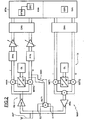
- the figure 1 illustrates an example of a wireless communication device or WAP transmitter belonging to an uncoordinated communication system such as a Wireless Local Area Network (WLAN) or Wireless Personal Area Network (WPAN).
- WLAN Wireless Local Area Network
- WPAN Wireless Personal Area Network
- Such a WAP wireless device belongs for example to an ultra wide band type communication system based on orthogonal frequency division multiplexing (UWB OFDM) modulation.
- UWB OFDM orthogonal frequency division multiplexing
- the WPAN-MAC protocols have a distributed nature in which there is no coordinating central terminal or base station for assigning accesses to the communication medium.
- a WPAN transmitter has greater flexibility to allocate transmission slots and transmission formats.
- the allocation of communication resources is therefore a distributed process.
- the allocation of a specific time interval in a superframe can be varied from one superframe to another.
- the control entity is the WPAN-MAC layer of the communication terminals. The allocation is based on the required data rate and the type of service to be transmitted. In addition, the available resources are taken into account in the allocation process.
- the MAC layer requests a reservation for a specific time interval or for multiple time slots depending on its constraints. Its constraints can be subdivided into local constraints such as the data rate to be transmitted or received and network level constraints such as the reservation already made for existing time slots.
- An example of a distributed protocol of the WPAN-MAC type is the MBOA-MAC protocol.
- the proposed MBOA standard is based on Ultra Wide Band (UWB) technology and is intended for use in the frequency band between 3.1 and 10.7 GHz.
- the wireless WAP device of the figure 1 comprises a communication interface of the UWB type based on an OFDM modulation, this interface being referenced MCINT and connected between a UWB application block referenced MBLC and the communication medium (here, the air).
- the MCINT communication interface comprises a MAC UWB layer synchronized by an MCLK clock signal and connected to a PHY layer as well as to the MBLC application block.
- the MAC and PHY layers are conventional layers and are known per se to those skilled in the art.
- the skilled person can refer to the MBOA PHY layer technical specification, version 1.0, January 2005, as well as the technical specification of MBOA MAC layer, version 0v7, October 2004.
- the MAC layer in particular controls the transmission / reception of the UWB data stream and is software incorporated into a control processor.
- the communication interface of the WAP device comprises a transmission channel having a TX analog part and a TXN digital part, and a receiving channel having an analog part RX and a digital part RXN.
- the transmission channel and the reception channel are of the direct conversion type.
- the two transmission and reception channels are coupled here to the antenna ANT by a duplexer for example.
- the transmission and reception chains operate here in a shared mode (Half Duplex according to an English name usually used), that is to say that the transmission and reception of the signals are not done simultaneously.
- the invention is not limited to an operating mode of the "Half Duplex” type, but can also be applied to an operating mode of the "Full Duplex” type according to a commonly used English name. that is, with simultaneous transmission and reception.
- TX transmission channel conventionally comprises two channels, one in phase I and the other in Q phase quadrature.
- the transmission channel TX comprises a transmission frequency transposition stage comprising here an MXTI mixer arranged on branch I and a mixer MXTQ arranged on the quadrature branch Q.
- the architecture of the WAP device is a differential architecture.
- the invention is not limited to this type of architecture and can also be applied to a single input type architecture (Single Ended according to an English name usually used).
- the two mixers MXTI and MXTQ each receive a transposition signal emitted by a local oscillator OL.
- the transposition signal delivered to the MXTQ mixer is 90 ° out of phase with the transposition signal supplied to the MXTI mixer.
- the output of the two mixers MXTI and MXTQ is connected to an adder whose output is connected to a power amplifier stage PPA.
- the output of the power amplifier PPA is connected to the antenna duplexer.
- the analog part of the reception channel RX conventionally comprises a low noise amplifier LNA whose input is connected to the antenna duplexer and the output of which is connected to a reception frequency transposition stage formed here by two MXRI mixers. and MXRQ respectively arranged on the two branches I and Q of reception.
- the transposition signal received by the mixer MXRQ is delivered by the local oscillator signal OL and shifted by 90 ° with respect to the transposition signal delivered to the mixer MXRI.
- each mixer is connected to a low-pass filter FPB for removing the mixture residues.
- the output of each FPB filter is connected to a CAN digital analog conversion stage via a variable gain amplifier.
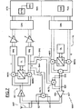
- the WAP device comprises first multiplication means, or multiplier, MLT1 whose two inputs E1 and E2 are connected downstream of the stage of the invention. PPA power amplification.
- the multiplier MLT1 itself multiplies the input signal and outputs this high input signal squared.
- the output of the multiplier MLT1 is connected to one of the branches, here the branch Q, of the receive channel RX, between the corresponding mixer MXRQ and the low-pass filter FPB.
- This connection is made via a switch SW1, formed for example of transistors controllable on their control electrode.
- This switch SW1 is controlled by a control signal emitted by the MAC layer.
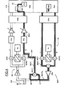
- a digital baseband symbol of the UWB-OFDM type is composed of 128 sub-carriers (corresponding conventionally and known to the data, the driver, etc.).
- the transmitted data is generated by calculating the IFFT inverse Fourier transform of 128 baseband digital samples in the frequency domain and completing the result with a number of zero-valued samples.
- the digital portion TXN of the transmission channel comprises a DC encoder, for example a convolutional encoder, receiving data from source coding means and delivering a bit stream to means of puncturing (Puncturing means according to an English name). - usually used) PM that deliver a punched bit stream.
- a DC encoder for example a convolutional encoder
- ILM interleaving means are connected to the output of the puncturing means PM and are followed by Mapping means (Mapping means according to a commonly used English name) which perform a conversion of bits into symbols, according to a schema of FIG. modulation depending on the type of modulation used, for example modulation of the BPSK type or more generally QAM modulation.
- Mapping means Mapping means according to a commonly used English name
- FIG. modulation depending on the type of modulation used, for example modulation of the BPSK type or more generally QAM modulation.
- the successive symbols delivered by the correspondence means MPM are digital symbols in baseband MB-OFDM (OFDM multiband).
- Each symbol is a group containing 128 modulation coefficients respectively associated with 128 sub-carriers to be modulated considering the respective coefficients.
- a group of 128 samples is delivered on the branch I while another corresponding group of 128 samples is delivered on the branch Q.
- the means belonging to the digital stage baseband can be made for example by software in a microprocessor. Another possibility may be to realize at least some of these means, for example the IFFTM means, using specific integrated circuits.
- the time domain symbols delivered by the OFDM IFFTM modulator are then processed in the analog transmit channel after being converted into a digital analog conversion stage CNA.
- the generation means GEN capable of generating the sampling signal can be realized in the present case by means of correspondence MPMA capable of delivering in the domain frequency a reference modulation coefficient associated with a selected subcarrier (a chosen frequency).
- the MPMA means can be made by identical means to the MPM correspondence means.
- These MPMA means may be, in the detection phase, connected to the input of the IFFTM means by a switch also activated by a control signal generated by the MAC control layer.
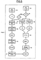
- a sinusoidal (or cosine) sampling signal referenced SEH i, is delivered on the transmission channel TX ( figure 4 ).
- the switch SW1 is closed (step 50) and the sampling signal SEH i , having the frequency f i , is generated (step 51).
- the frequency f i of the sampling signal is selected in the baseband frequency range, which in this case ranges from 0 to 264 MHz.
- the transposed sampling signal SEHT i is amplified in the power amplification stage PPA (step 53) and the amplified transposed signal SEHTA i is then squared in the first multiplier MLT1.
- the squared signal SEC1 i has frequency components lying around twice the frequency F of the oscillator as well as frequency components having the frequency f i of the baseband sampling signal and the frequency 2f i .
- Frequency components lying around twice the frequency of the local oscillator signal are components that are not troublesome since they are outside the frequency band of the useful signal and will therefore be filtered.
- the frequency components having the frequencies f i and 2f i which result from imperfections of the transmission channel, are, as a function of the value of the frequency f i , in the base band and can therefore interfere with the wanted signals received on the receive channel.
- the squared signal SEC1 i is then filtered (step 55) in the low-pass filter FPB of the reception path so as to eliminate the radio frequency components.
- the filtered signal SECF i is then, after amplification, converted into the digital domain and transformed in the frequency domain by means of FFTM direct Fourier transform (step 56).
- the initial frequency range (baseband) is then scanned by changing the sampling frequency of the generated sampling signal (step 59) and the sequence of the steps just described is repeated.
- baseband the sampling frequency of the generated sampling signal
- the level of the frequency component CF i is representative of the local oscillator leak. In practice, this can be corrected by injecting into the mixer a dc offset voltage for example equal to the opposite of the voltage level measured in the quadratic detector DTC.
- the level of the frequency component C2F i is in turn more representative of an error known to those skilled in the art under the name Anglosaxonne EVM and representative of a deviation from an ideal constellation. This results from a mismatch between the branches I and Q and can also be corrected in a known manner.
- the invention makes it possible to detect imperfections in the transmission channel, regardless of the radio frequency level of the transmitted signal, but particularly for low level signals such as UWB signals for which a detection in the field Radio frequency was difficult to achieve in an integrated manner throughout the radio frequency band of the useful signal.
- the voltages V1 and V2 designate the two inputs of the cell and the differential output formed by the collectors of the transistors M 3 and M 5 on the one hand and M 4 and M 6 on the other hand, delivers the current I out corresponding to the SEC1 signal i .
- the first stage of the Gilbert cell is formed of two other MOS transistors M 1 and M 2 biased by a current source Ib.
- FIG. 7 a second embodiment of a device according to the invention.
- This second embodiment differs from that described with reference to the figure 4 in that a second multiplier MLT2, of structure similar to that of the first multiplier MLT1, is provided, but whose two inputs E10 and E20 are this time connected upstream of the power amplifier PPA.
- the output of the second multiplier MLT2 is also connected upstream of the low-pass filter FPB via a switch SW2 also controllable by the MAC layer.
- a deactivation signal ACT of the power amplifier stage PPA can also be emitted.
- This embodiment is particularly advantageous because it makes it possible to measure more precisely the level of the frequency component having the frequency 2f i . Indeed, the level of this component is lower than the level of the frequency component having the frequency f i . Under these conditions, by deactivating the power amplifier by means of the signal ACT, it is possible to deliver a sampling signal SEH i having a much higher level, which allows, as illustrated on FIG. figure 8 to obtain a more precise measurement of the frequency component C2F i .
- this second phase of detection which is also illustrated on the figure 9 , also makes it possible to measure the level of the frequency component CF i having the frequency f i .
- this second detection phase is analogous to the first detection phase PHD1 1 with the difference that the transposed sampling signal SEHT i is directly squared (step 83) to provide the signal squared SEC2 i .
- the first detection phase PHD1 (step 91) as well as the second detection phase PHD2 (step 92) are generally used when the WAP device is turned on (step 90).
- the two detection phases PHD1 and PHD2 can then also advantageously be carried out during periods of inactivity in transmitting and receiving the device. These periods of inactivity are known to the MAC layer.
Landscapes
- Engineering & Computer Science (AREA)
- Computer Networks & Wireless Communication (AREA)
- Signal Processing (AREA)
- Physics & Mathematics (AREA)
- Nonlinear Science (AREA)
- Power Engineering (AREA)
- Transmitters (AREA)
Claims (18)
- Verfahren zur Erfassung von Störstellen des Sendekanals einer Hochfrequenzvorrichtung vom Typ mit Direktumwandlung, die eine Sendefrequenz-Umsetzungsstufe aufweist, welche ein Signal im Basisband, dessen Frequenz sich in einem Anfangsfrequenzbereich befindet, in ein Hochfrequenzsignal umsetzen kann, wobei das Verfahren mindestens eine erste Erfassungsphase (PHD1) enthält, in der ein Kalibriersignal (SEHi) im Basisband erzeugt wird (51), das eine im Anfangsbereich gewählte Kalibrierfrequenz (f) hat, ein umgesetztes Kalibriersignal (SEHTAi), das vom Kalibriersignal im Basisband stammt und hinter der Sendefrequenz-Umsetzungsstufe entnommen wird, mit sich selbst multipliziert wird, um ein quadriertes umgesetztes Signal zu erhalten, das quadrierte umgesetzte Signal (SEC1i) gefiltert wird, um daraus die Hochfrequenzkomponenten zu entfernen, und mindestens der Pegel der Frequenzkomponente (CFi) des gefilterten Signals (SECFi) gemessen wird, die die Kalibrierfrequenz (fi) hat, dadurch gekennzeichnet, dass, da der Sendekanal eine Leistungsverstärkungsstufe (PPA) aufweist, die hinter der Sendefrequenz-Umsetzungsstufe angeordnet ist, das umgesetzte Kalibriersignal (SEHTAi) hinter der Leistungsverstärkungsstufe entnommen wird, und dass das Verfahren außerdem eine zweite Erfassungsphase (PHD2) aufweist, die zu einem anderen Zeitpunkt als die erste Erfassungsphase (PHD1) durchgeführt wird, während der die Leistungsverstärkungsstufe (PPA) deaktiviert wird, ein Kalibriersignal im Basisband erzeugt wird (81), das eine im Anfangsbereich ausgewählte Kalibrierfrequenz hat, das umgesetzte Kalibriersignal vor der Leistungsverstärkungsstufe entnommen wird, das umgesetzte Kalibriersignal mit sich selbst multipliziert wird, das quadrierte umgesetzte Signal (SEC2i) gefiltert wird, um daraus die Hochfrequenzkomponenten zu entfernen, und mindestens der Pegel der Frequenzkomponente (C2Fi) des gefilterten Signals gemessen wird, die die doppelte Kalibrierfrequenz hat.
- Verfahren nach Anspruch 1, bei dem die erste Erfassungsphase (PHD1) außerdem eine Messung des Pegels der Frequenzkomponente (C2Fi) des gefilterten Signals aufweist, die die doppelte Kalibrierfrequenz hat.
- Verfahren nach einem der vorhergehenden Ansprüche, bei dem die Messung des Pegels einer Frequenzkomponente des gefilterten Signals eine Transformation des gefilterten Signals im Frequenzbereich (FFTM) und eine Pegelmessung der Tastproben aufweist, die der Frequenzkomponente entsprechen.
- Verfahren nach einem der vorhergehenden Ansprüche, bei dem in jeder Erfassungsphase mehrere Kalibriersignale (SEHi) erzeugt werden, die unterschiedliche Kalibrierfrequenzen haben, welche im Anfangsfrequenzbereich ausgewählt werden, und die Pegel der entsprechenden Frequenzkomponenten gemessen werden.
- Verfahren nach einem der vorhergehenden Ansprüche, bei dem jedes Kalibriersignal (SEHi) ein Signal vom Sinustyp ist.
- Verfahren nach einem der vorhergehenden Ansprüche, bei dem die Vorrichtung ebenfalls einen Empfangskanal aufweist, der ein Tiefpassfilter (FPB) aufweist, das hinter einer Empfangsfrequenz-Umsetzungsstufe angeordnet ist, und das quadrierte umgesetzte Signal im Tiefpassfilter des Empfangskanals gefiltert wird.
- Verfahren nach einem der vorhergehenden Ansprüche, bei dem jede Erfassungsphase beim Unterspannungsetzen der Vorrichtung (90) durchgeführt wird.
- Verfahren nach einem der vorhergehenden Ansprüche, bei dem jede Erfassungsphase während Sende- und Empfangs-Inaktivitätsperioden der Vorrichtung durchgeführt wird, insbesondere bei Temperaturänderungen (100).
- Hochfrequenzvorrichtung vom Typ mit Direktumwandlung, die eine Sendefrequenz-Umsetzungsstufe aufweist, die ein Signal im Basisband, dessen Frequenz sich in einem Anfangsfrequenzbereich befindet, in ein Hochfrequenzsignal umsetzen kann, dadurch gekennzeichnet, dass sie mindestens erste aktivierbare Erfassungseinrichtungen, die erste Erzeugungseinrichtungen (GEN) aufweisen, welche ein Kalibriersignal (SEHi) im Basisband erzeugen können, das eine im Anfangsbereich ausgewählte Kalibrierfrequenz hat, erste Multiplikationseinrichtungen (MLT1), deren beide Eingänge hinter der Sendefrequenz-Umsetzungsstufe (MXT1, MXTQ) verbunden sind, um ein quadriertes umgesetztes Signal zu liefern, das von dem Kalibriersignal im Basisband stammt, erste Filtereinrichtungen (FPB), die das quadrierte umgesetzte Signal filtern können, um daraus die Hochfrequenzkomponenten zu entfernen, und erste Messeinrichtungen (FFTM, DTC) enthält, die mindestens den Pegel der Frequenzkomponente des gefilterten Signals, die die Kalibrierfrequenz hat, messen können, dadurch gekennzeichnet, dass der Sendekanal eine Leistungsverstärkungsstufe (PPA) aufweist, die hinter der Sendefrequenz-Umsetzungsstufe angeordnet ist, und die zwei Eingänge (E1, E2) der ersten Multiplikationseinrichtungen hinter der Leistungsverstärkungsstufe (PPA) verbunden sind, und dass die Vorrichtung außerdem zweite aktivierbare Erfassungseinrichtungen, die zweite Erzeugungseinrichtungen (GEN) aufweisen, welche ein Kalibriersignal im Basisband erzeugen können, das eine im Anfangsbereich ausgewählte Kalibrierfrequenz hat, zweite Multiplikationseinrichtungen (MLT2), deren zwei Eingänge hinter der Sendefrequenz-Umsetzungsstufe und vor der Leistungsverstärkungsstufe verbunden sind, um ein quadriertes umgesetztes Signal zu liefern, das von dem Kalibriersignal im Basisband stammt, zweite Filtereinrichtungen (FPB), die das quadrierte umgesetzte Signal filtern können, um daraus die Hochfrequenzkomponenten zu entfernen, und zweite Messeinrichtungen (FFTM, DTC) aufweist, die mindestens den Pegel der Frequenzkomponente des gefilterten Signals, die die doppelte Kalibrierfrequenz hat, messen können, und die Vorrichtung außerdem Steuereinrichtungen aufweist, die die Leistungsverstärkungsstufe (PPA) und die ersten Erfassungseinrichtungen deaktivieren können, um die zweiten Erfassungseinrichtungen zu aktivieren.
- Vorrichtung nach Anspruch 9, bei der die ersten Messeinrichtungen (FFTM, DTC) außerdem den Pegel der Frequenzkomponente des gefilterten Signals messen können, die die doppelte Kalibrierfrequenz hat.
- Vorrichtung nach Anspruch 9 oder 10, bei der die ersten und zweiten Erzeugungseinrichtungen gemeinsame Einrichtungen (GEN) sind, die ersten und zweiten Filtereinrichtungen gemeinsame Einrichtungen (FPB) sind, und die ersten und zweiten Messeinrichtungen gemeinsame Einrichtungen (FFTM, DTC) sind.
- Vorrichtung nach einem der Ansprüche 9 bis 11, bei der die ersten Multiplikationseinrichtungen (MLT1) und ggf. die zweiten Multiplikationseinrichtungen (MLT2) eine Gilbert-Zelle aufweisen, deren Transistoren im linearen Betrieb arbeiten.
- Vorrichtung nach einem der Ansprüche 9 bis 12, bei der die ersten und ggf. die zweiten Messeinrichtungen Einrichtungen (FFTM), die eine Transformation des gefilterten Signals im Frequenzbereich durchführen können, und Pegelmesseinrichtungen (DTC) der Tastproben aufweisen, die der Frequenzkomponente entsprechen.
- Vorrichtung nach einem der Ansprüche 9 bis 13, bei der die ersten und ggf. die zweiten Erzeugungseinrichtungen (GEN) mehrere Kalibriersignale erzeugen können, die unterschiedliche Kalibrierfrequenzen haben, die im Anfangsfrequenzbereich ausgewählt werden, und die zugeordneten Messeinrichtungen die Pegel der entsprechenden Frequenzkomponenten messen können.
- Vorrichtung nach einem der Ansprüche 9 bis 14, bei der jedes Kalibriersignal ein Signal vom Sinustyp ist.
- Vorrichtung nach einem der Ansprüche 9 bis 15, die ebenfalls einen Empfangskanal enthält, der ein Tiefpassfilter (FPB) aufweist, das hinter einer Empfangsfrequenz-Umsetzungsstufe angeordnet ist und die ersten und ggf. die zweiten Filtereinrichtungen bildet.
- Vorrichtung nach einem der Ansprüche 9 bis 16, bei der die Steuereinrichtungen (MAC) die ersten Erfassungseinrichtungen und ggf. die zweiten Erfassungseinrichtungen beim Unterspannungsetzen der Vorrichtung aktivieren können.
- Vorrichtung nach einem der Ansprüche 9 bis 17, die außerdem einen Temperaturmessfühler aufweist, und bei der die Steuereinrichtungen (MAC) die ersten Erfassungseinrichtungen und ggf. die zweiten Erfassungseinrichtungen während Sende- und Empfangs-Inaktivitätsperioden der Vorrichtung, insbesondere bei Temperaturänderungen, aktivieren können, die vom Temperaturmessfühler erfasst werden.
Priority Applications (2)
| Application Number | Priority Date | Filing Date | Title |
|---|---|---|---|
| DE602006009627T DE602006009627D1 (de) | 2006-04-26 | 2006-04-26 | Verfahren zur Detektion von Verzerrung in einem Sendepfad eines Direktkonversionshochfrequenzgerätes und Vorrichtung hierzu |
| EP06008615A EP1850488B1 (de) | 2006-04-26 | 2006-04-26 | Verfahren zur Detektion von Verzerrung in einem Sendepfad eines Direktkonversionshochfrequenzgerätes und Vorrichtung hierzu |
Applications Claiming Priority (1)
| Application Number | Priority Date | Filing Date | Title |
|---|---|---|---|
| EP06008615A EP1850488B1 (de) | 2006-04-26 | 2006-04-26 | Verfahren zur Detektion von Verzerrung in einem Sendepfad eines Direktkonversionshochfrequenzgerätes und Vorrichtung hierzu |
Publications (2)
| Publication Number | Publication Date |
|---|---|
| EP1850488A1 EP1850488A1 (de) | 2007-10-31 |
| EP1850488B1 true EP1850488B1 (de) | 2009-10-07 |
Family
ID=36972908
Family Applications (1)
| Application Number | Title | Priority Date | Filing Date |
|---|---|---|---|
| EP06008615A Expired - Lifetime EP1850488B1 (de) | 2006-04-26 | 2006-04-26 | Verfahren zur Detektion von Verzerrung in einem Sendepfad eines Direktkonversionshochfrequenzgerätes und Vorrichtung hierzu |
Country Status (2)
| Country | Link |
|---|---|
| EP (1) | EP1850488B1 (de) |
| DE (1) | DE602006009627D1 (de) |
Families Citing this family (2)
| Publication number | Priority date | Publication date | Assignee | Title |
|---|---|---|---|---|
| CN111614407B (zh) * | 2020-03-30 | 2022-04-01 | 西南电子技术研究所(中国电子科技集团公司第十研究所) | 飞行器测控系统基带零值自动监测方法 |
| CN114070430B (zh) * | 2020-07-29 | 2022-09-16 | 大唐移动通信设备有限公司 | 一种天线校准的触发方法和装置 |
Family Cites Families (4)
| Publication number | Priority date | Publication date | Assignee | Title |
|---|---|---|---|---|
| US6298096B1 (en) * | 1998-11-19 | 2001-10-02 | Titan Corporation | Method and apparatus for determination of predistortion parameters for a quadrature modulator |
| WO2003043206A2 (de) * | 2001-11-13 | 2003-05-22 | Infineon Technologies Ag | Sendeanordnung mit automatischem abgleich des quadraturmodulators |
| US7305024B2 (en) * | 2003-08-29 | 2007-12-04 | Texas Instruments Incorporated | Method of fixing frequency complex up-conversion phase and gain impairments |
| KR100602642B1 (ko) * | 2004-01-30 | 2006-07-19 | 삼성전자주식회사 | 무선 기지국 시스템에서의 위상 에러 보정장치 및 그 방법 |
-
2006
- 2006-04-26 DE DE602006009627T patent/DE602006009627D1/de not_active Expired - Lifetime
- 2006-04-26 EP EP06008615A patent/EP1850488B1/de not_active Expired - Lifetime
Also Published As
| Publication number | Publication date |
|---|---|
| EP1850488A1 (de) | 2007-10-31 |
| DE602006009627D1 (de) | 2009-11-19 |
Similar Documents
| Publication | Publication Date | Title |
|---|---|---|
| EP0709980B1 (de) | Frequenzsynchronisierung für OFDM-System | |
| JP5287521B2 (ja) | 通信装置 | |
| EP1446928B1 (de) | Adaptive vorverzerrung eines phasen- oder frequenz-modulierten und amplituden-modulierten funkfrequenzsignalgenerators | |
| EP1924003A2 (de) | Vorrichtungen und Verfahren zur Kompensation des Signalungleichgewichts in einem Empfangsgerät | |
| FR2746563A1 (fr) | Procede pour corriger des non-linearites d'un amplificateur, et emetteur radio mettant en oeuvre un tel procede | |
| EP1447952A1 (de) | Verfahren und Einrichtung zur Analyse eines OFDM-Signals | |
| EP1306978B1 (de) | Direktmischempfänger für einem Kommunikationssystem mit nicht konstanter Hüllkurve | |
| US20050026577A1 (en) | Method and apparatus for I/Q mismatch calibration in a receiver | |
| FR2897215A1 (fr) | Dispositif et procede d'annulation des interferences | |
| WO2007101885A1 (fr) | Dispositif de recepion et/ou d'emission de signaux radiofrequences a reduction du bruit | |
| EP1850488B1 (de) | Verfahren zur Detektion von Verzerrung in einem Sendepfad eines Direktkonversionshochfrequenzgerätes und Vorrichtung hierzu | |
| EP2854354B1 (de) | Verfahren zur Bestimmung von Störstellen eines Sende- und eines Empfangswegs eines Geräts und dazugehörige Vorrichtung | |
| EP1417750A1 (de) | Mischerschaltung mit spiegelfrequenzunterdrückung , und deren verwendung in einem direktkonversionsempfänger | |
| FR2669165A1 (fr) | Appareil et procede permettant de faire varier un signal dans l'emetteur d'un emetteur-recepteur. | |
| EP2255466A2 (de) | Breitband-mehrkanalfunkfrequenzempfänger | |
| US7746960B2 (en) | Apparatus and method for compensating for I/Q mismatch in TDD system | |
| EP2533428A1 (de) | Drahtloses Multistandardsender | |
| EP3780529A1 (de) | Vorrichtung und verfahren für die signalisierung von kommunikationen über ein fragmentiertes spektrum | |
| FR2859055A1 (fr) | Procede et dispositif de traitement des defauts d'appariement entre deux voies en quadrature d'une chaine d'une reception adaptee par exemple a la reception d'un signal module selon une modulation du type ofdm | |
| FR2914515A1 (fr) | Calibration dans un module d'emission radio frequence | |
| Arslan | RF impairments | |
| EP1925139B1 (de) | Charakterisierung von radiospektren für kommunikationsvorrichtungen | |
| EP2060006B1 (de) | Verfahren und ausrüstung zur signalübertragung mittels filterung in einem spiegelband | |
| EP3840233A1 (de) | Schaltkreis zur hüllkurvenerfassung und empfänger, der diesen schaltkreis enthält | |
| WO2019179651A1 (fr) | Module de generation d'options de reception de signaux radio |
Legal Events
| Date | Code | Title | Description |
|---|---|---|---|
| PUAI | Public reference made under article 153(3) epc to a published international application that has entered the european phase |
Free format text: ORIGINAL CODE: 0009012 |
|
| AK | Designated contracting states |
Kind code of ref document: A1 Designated state(s): AT BE BG CH CY CZ DE DK EE ES FI FR GB GR HU IE IS IT LI LT LU LV MC NL PL PT RO SE SI SK TR |
|
| AX | Request for extension of the european patent |
Extension state: AL BA HR MK YU |
|
| 17P | Request for examination filed |
Effective date: 20080424 |
|
| AKX | Designation fees paid |
Designated state(s): DE FR GB IT |
|
| 17Q | First examination report despatched |
Effective date: 20080627 |
|
| GRAP | Despatch of communication of intention to grant a patent |
Free format text: ORIGINAL CODE: EPIDOSNIGR1 |
|
| GRAS | Grant fee paid |
Free format text: ORIGINAL CODE: EPIDOSNIGR3 |
|
| GRAA | (expected) grant |
Free format text: ORIGINAL CODE: 0009210 |
|
| AK | Designated contracting states |
Kind code of ref document: B1 Designated state(s): DE FR GB IT |
|
| REG | Reference to a national code |
Ref country code: GB Ref legal event code: FG4D Free format text: NOT ENGLISH |
|
| REF | Corresponds to: |
Ref document number: 602006009627 Country of ref document: DE Date of ref document: 20091119 Kind code of ref document: P |
|
| PLBE | No opposition filed within time limit |
Free format text: ORIGINAL CODE: 0009261 |
|
| STAA | Information on the status of an ep patent application or granted ep patent |
Free format text: STATUS: NO OPPOSITION FILED WITHIN TIME LIMIT |
|
| 26N | No opposition filed |
Effective date: 20100708 |
|
| REG | Reference to a national code |
Ref country code: FR Ref legal event code: ST Effective date: 20101230 |
|
| PG25 | Lapsed in a contracting state [announced via postgrant information from national office to epo] |
Ref country code: IT Free format text: LAPSE BECAUSE OF FAILURE TO SUBMIT A TRANSLATION OF THE DESCRIPTION OR TO PAY THE FEE WITHIN THE PRESCRIBED TIME-LIMIT Effective date: 20091007 |
|
| PG25 | Lapsed in a contracting state [announced via postgrant information from national office to epo] |
Ref country code: FR Free format text: LAPSE BECAUSE OF NON-PAYMENT OF DUE FEES Effective date: 20100430 |
|
| PGFP | Annual fee paid to national office [announced via postgrant information from national office to epo] |
Ref country code: GB Payment date: 20200323 Year of fee payment: 15 |
|
| PGFP | Annual fee paid to national office [announced via postgrant information from national office to epo] |
Ref country code: DE Payment date: 20200319 Year of fee payment: 15 |
|
| REG | Reference to a national code |
Ref country code: DE Ref legal event code: R119 Ref document number: 602006009627 Country of ref document: DE |
|
| GBPC | Gb: european patent ceased through non-payment of renewal fee |
Effective date: 20210426 |
|
| PG25 | Lapsed in a contracting state [announced via postgrant information from national office to epo] |
Ref country code: GB Free format text: LAPSE BECAUSE OF NON-PAYMENT OF DUE FEES Effective date: 20210426 Ref country code: DE Free format text: LAPSE BECAUSE OF NON-PAYMENT OF DUE FEES Effective date: 20211103 |