EP1583306A2 - Mehrträgerempfänger mit Einschätzung der Zeitvarianz des Kanals - Google Patents
Mehrträgerempfänger mit Einschätzung der Zeitvarianz des Kanals Download PDFInfo
- Publication number
- EP1583306A2 EP1583306A2 EP05101840A EP05101840A EP1583306A2 EP 1583306 A2 EP1583306 A2 EP 1583306A2 EP 05101840 A EP05101840 A EP 05101840A EP 05101840 A EP05101840 A EP 05101840A EP 1583306 A2 EP1583306 A2 EP 1583306A2
- Authority
- EP
- European Patent Office
- Prior art keywords
- circuit
- pilot
- transmission channel
- frequency response
- complex coefficient
- Prior art date
- Legal status (The legal status is an assumption and is not a legal conclusion. Google has not performed a legal analysis and makes no representation as to the accuracy of the status listed.)
- Granted
Links
Images


Classifications
-
- H—ELECTRICITY
- H04—ELECTRIC COMMUNICATION TECHNIQUE
- H04L—TRANSMISSION OF DIGITAL INFORMATION, e.g. TELEGRAPHIC COMMUNICATION
- H04L25/00—Baseband systems
- H04L25/02—Details ; arrangements for supplying electrical power along data transmission lines
- H04L25/0202—Channel estimation
- H04L25/022—Channel estimation of frequency response
-
- H—ELECTRICITY
- H04—ELECTRIC COMMUNICATION TECHNIQUE
- H04L—TRANSMISSION OF DIGITAL INFORMATION, e.g. TELEGRAPHIC COMMUNICATION
- H04L25/00—Baseband systems
- H04L25/02—Details ; arrangements for supplying electrical power along data transmission lines
- H04L25/0202—Channel estimation
-
- H—ELECTRICITY
- H04—ELECTRIC COMMUNICATION TECHNIQUE
- H04L—TRANSMISSION OF DIGITAL INFORMATION, e.g. TELEGRAPHIC COMMUNICATION
- H04L25/00—Baseband systems
- H04L25/02—Details ; arrangements for supplying electrical power along data transmission lines
- H04L25/0202—Channel estimation
- H04L25/0224—Channel estimation using sounding signals
-
- H—ELECTRICITY
- H04—ELECTRIC COMMUNICATION TECHNIQUE
- H04L—TRANSMISSION OF DIGITAL INFORMATION, e.g. TELEGRAPHIC COMMUNICATION
- H04L27/00—Modulated-carrier systems
- H04L27/26—Systems using multi-frequency codes
- H04L27/2601—Multicarrier modulation systems
- H04L27/2647—Arrangements specific to the receiver only
Definitions
- the present invention relates to a demodulator Coded Orthogonal Frequency Division Multiplex (COFDM) by orthogonal frequency division coded).
- COFDM Coded Orthogonal Frequency Division Multiplex
- Figure 1 is intended to illustrate the principle of COFDM modulation.
- Data packets to be sent are put under the form of N complex coefficients associated with N frequencies (or carriers).
- the number N of the frequencies is equal to example at 1705 for the so-called “2K” mode and at 6817 for the so-called “2K” mode.
- “8K” in digital terrestrial television transmission.
- Each complex coefficient corresponds to a vector that is illustrated in Figure 1 as starting from a frequency axis at a point indicating the frequency associated with the coefficient.
- IFFT transform Fourier Fast Reverse
- the useful life is of the order of 224 ⁇ s in 2K mode and 896 ⁇ s in 8K mode, for a bandwidth of 8 MHz.
- a receiver makes the symbol reverse treatment, that is to say mainly a transformed Fourier Fast (FFT) to reconstruct the coefficients starting complexes.
- FFT transformed Fourier Fast
- the receiver actually receives the signal from the transmitter as well as a multitude of attenuated signals and delayed from different echoes.
- the channel of transmission borrowed by the signal to be demodulated, is then said multipath.
- Such a channel has a frequency response which is not flat, but has depressions and bumps due echoes and reflections between transmitter and receiver.
- the channel is called fixed type when it has a frequency response substantially constant in time.
- the canal is said variable type in time when he has an answer Frequency that evolves over time.
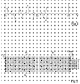
- Figure 2 shows schematically the place of drivers in the symbols.
- the symbols are grouped into frames of 68 symbols, in a conventional way in radio transmission of digital television (ETSI EN 300 744, V1.4.1).
- each line represents a symbol and each box represents the position of a carrier.
- the carriers are defined as going from a 0 position to a Kmax position, Kmax being equal to 1704 in 2K mode and 6816 in 8K mode. Indeed, only a part of the possible frequencies is used, in particular as a result of the risk of loss along the canal.
- Continuous and distributed pilots are used to know the answer frequency and impulse channel.
- the signal received complex, temporal, after being put in baseband is provided to a Fourier transformer fast providing the symbol in the frequency domain.
- the pilots are taken from this symbol.
- An estimate of the Frequency response of the channel is determined from the continuous and distributed pilots taken from four symbols successive.
- the estimate of the frequency response is used to correct vectors associated with carriers located between the pilots.
- Impulse response of the channel obtained from the inverse Fourier transform estimation of the frequency response, in particular used to finely position a window on which is performed the fast Fourier transform.
- COFDM demodulator Many operating parameters of the COFDM demodulator are generally optimized during operation of COFDM to improve the performance of the demodulator.
- a method for adjusting the parameters of operation of the demodulator is to analyze the data received after full decoding and to determine their error rate BER ("Bit Error Rate").
- the parameters of operation of the demodulator described above can then be modified by trial and error until the rate error is acceptable.
- Another criterion for measuring the quality of the demodulation corresponds to the signal-to-noise ratio SNR ("Signal Noise Ratio "in English) that can be determined during Extraction of continuous or distributed pilots.
- the operating parameters of the demodulator can be optimized, some depend on the fixed or variable in the time of the channel. For example, depending on the nature of channel, a particular process may be favored for determine the frequency response of the channel thus allowing to obtain an accurate estimate of the response more efficiently frequency of the channel.
- a particular process may be favored for determine the frequency response of the channel thus allowing to obtain an accurate estimate of the response more efficiently frequency of the channel.
- the complex signal is usually corrected frequentially and temporally by algorithms time constants that can be adjusted in depending on the type of the channel.
- the method of optimizing the parameters of operation of the demodulator using the BER error rate is relatively imprecise and slow with regard to operating parameters that can be optimized according to the type of the transmission channel. Indeed, it is necessary to wait for the complete decoding of the data, which can be very long. A modification of the operating parameters of the demodulator to from such a criterion is therefore achieved well after a channel evolution, and therefore usually too late to avoid a loss of data.
- the BER error rate does not indicate not in what way should the parameters of operation of the demodulator to improve performance. Indeed, a correct adjustment of the parameters of operation of the demodulator will be found only by a subsequent decrease of the error rate.
- the present invention relates to a method and a circuit, for COFDM demodulator, providing an indicator allowing to quickly and accurately adjust the parameters of operation of the demodulator can be optimized according to fixed type or variable in time of the transmission channel.
- this invention relates to a method and a circuit providing a representative indicator of how should be adjusted the operating parameters of the demodulator can be optimized according to the fixed or variable type in the channel time transmission
- the present invention provides a COFDM demodulator comprising a transform circuit of Fast Fourier receiving a signal by a transmission channel, the received signal corresponding to a sequence of symbols conveying each several carriers some of which are pilots, each carrier of a symbol being modulated in phase and / or in amplitude by a current complex coefficient, said fast Fourier transform providing for each carrier the associated common complex coefficient; a circuit of determining an estimate of the frequency response of the transmission channel providing, for each pilot, a complex coefficient estimated from the complex coefficient current associated with the pilot; and a quantization circuit of the temporal variation of the frequency response of the transmission from the estimated complex numbers and current associated with at least one driver.
- the circuit for determining the estimate of the response frequency includes a circuit to provide, for each pilot of a symbol, a differential complex coefficient obtained from the difference between the complex coefficients current and estimated associated with the pilot.
- the quantization circuit of the temporal variation of the frequency response of the transmission channel includes a circuit to provide a first representative value of the module of the estimated complex coefficient associated with the pilot; a circuit for providing a second representative value of the module the differential complex coefficient associated with the pilot; and one circuit to provide an instant indicator of the variation time of the frequency response of the transmission channel for the pilot, corresponding to the ratio between the second value and the first value.
- the quantization circuit of the temporal variation of the frequency response of the transmission channel includes a circuit to determine the sum of the instantaneous indicators for all the drivers of a symbol.
- the quantization circuit of the temporal variation of the frequency response of the transmission channel includes a circuit to determine an average indicator equal to the average time of the sum of the instantaneous indicators.
- the demodulator comprises a correction circuit receiving the average indicator and modifying an operating parameter of the demodulator according to the average indicator.
- the present invention also provides a method of demodulation type COFDM comprising a step of fast Fourier transform of a signal received from a transmission channel, the received signal corresponding to a sequence symbols each carrying several carriers, some of which are drivers, each carrier of a symbol being modulated in phase and / or amplitude by a common complex coefficient; a step of determining an estimate of the response frequency of the transmission channel from the coefficients common complexities associated with pilots; and a step of quantification of the temporal variation of the response frequency of the transmission channel consisting in providing, for each pilot, a complex coefficient associated with the pilot at from the estimated complex coefficient associated with at least one pilot and the current complex coefficient associated with the pilot.
- the step of quantifying the temporal variation of the Frequency response of the transmission channel includes the steps of providing a first representative value the module of the estimated complex coefficient associated with the pilot; at provide a second representative value of the module of a differential complex coefficient obtained from the difference between the current and estimated complex coefficients associated with the pilot; and provide an instant indicator of the temporal variation of the frequency response of the transmission for the pilot, corresponding to the ratio between second value and the first value.
- the step of quantifying the temporal variation of the Frequency response of the transmission channel includes the determination of the sum of the instant indicators for all the drivers of a symbol.
- the step of quantifying the temporal variation of the Frequency response of the transmission channel includes the determination of the temporal average of the sum of instant indicators.
- the present invention aims to provide, almost instantaneously, a representative indicator of the fixed or variable in the time of the transmission channel. This allows to obtain a good quality demodulation since the adjustments to the operating parameters of the demodulator that depend on the type of the transmission channel can then be made very quickly.
- Figure 3 shows an example of a demodulator according to the present invention.
- the received signal includes in particular continuous pilots, distributed pilots, and carriers of data.
- an input E of the demodulator receives a IF signal of intermediate frequency allowing a sampling, for example at 36 MHz.
- the IF signal corresponds the signal received after various changes or transpositions of frequency.
- Input E is coupled to an analog-to-digital converter 10 (ADC) which digitizes the IF input signal.
- ADC analog-to-digital converter 10
- the analog-to-digital converter 10 attacks a module 11 of suppression of impulse interference.
- Module 11 provides a signal corresponding to the signal provided by the analog-to-digital converter 10 in which the Impulse interferences have been removed.
- Module 11 attacks a module 12 of frequency change.
- Module 12 provides a substantially baseband signal, the spectrum of the signal at the output of the module 12 being centered on a frequency substantially equal to zero.
- the module 12 is coupled to a module 14 allowing on the one hand a fine adjustment of the central frequency of the signal spectrum and, on the other hand, to provide temporal samples at times appropriate to the treatment ulterior.
- the spectrum of the signal is centered on a frequency equal to 0 and the number and the position temporal samples are suitable for transformation by Fourier transform that takes place in the next module.
- the module 14 is controlled by links 15 and 15 'connecting the module 14 to a module 16 of continuous pilot processing and distributed.
- the output of the module 14 attacks a module 20 of Fast Fourier Transform (FFT) which provides the frequencies corresponding to a symbol.
- FFT Fast Fourier Transform
- the module 20 is driven by a module 22 which provides, via a link 24, a signal of adjustment of the analysis window of the transform of Fourier.
- module 20 The output of module 20 is coupled to module 16 which performs the extraction and processing of continuous pilots and distributed.
- the module 16 provides on the links 15 and 15 'the signals intended to correct the center frequency of the spectrum and the sampling frequency of the signal.
- the output of the module 20 attacks a module 30 in which the signal is corrected using an estimate of the Frequency response of the channel.
- the estimate of the answer frequency of the channel is achieved in module 16 using pilots. This estimate is provided by Module 16 on a link 55, a branch 55a of which is coupled to the module 30.
- the signal comprises the carriers corrected data conveying.
- the estimation of the frequency response of the channel, provided by module 16, feeds, via the link 55 and a branch 55b of the link 55, a module 26 inverse Fourier transform (IFFT), to determine the impulse response of the channel.
- Module 26 provides the answer impulse channel to module 22, to dynamically adjust the positioning of the FFT analysis window.
- the processing of the carriers carrying the data is assured in a circuit 40 of treatment and supply of data.
- the circuit 40 has a conventional structure and can comprise, as shown in FIG. 3, a module 42 deinterleaving symbols, a module 44 said to "demapping", a bit deinterleaving module 46, and a error correction module 48 (FEC).
- the output of module 48 constitutes the output S of the circuit 40 and the demodulator and provides data corresponding to the data sent.
- FIG. 4 represents an embodiment example more detailed circuit 50 which corresponds to the part of the module 16 on the determination of the estimate of the answer frequency of the channel.
- the circuit 50 is used in the integrated circuit STV0360E, marketed by the applicant.
- the circuit 50 is duplicated for each pilot, continuous and distributed, contained in a symbol, and for a pilot considered, the circuit 50 is duplicated for the real part and for the part imaginary complex coefficient associated with the pilot.
- the operation of the various components of the circuit 50 is synchronized by a clock signal not shown.
- the circuit 50 receives as input a PILOT signal corresponding to the real part or the imaginary part of the complex coefficient associated with a pilot extracted by another part of the module 16 not shown.
- the circuit 50 includes a circuit 60, also called static estimator, which determines for example, the time average of the PILOT signal.
- the PILOT signal is a coded digital signal on eight signed bits.
- the circuit 60 comprises a multiplication module 62 receiving the PILOT signal and the contents of a memory 64 in which is stored an MP gain.
- the multiplication module 62 provides the PILOT signal multiplied by the MP gain at a first input of an adder 66.
- the output signal of the adder 66 is stored in a flip-flop (L) 68.
- a module of multiplication 70 multiplies the contents of the latch 68 by a 1-MP gain stored in a memory 72.
- the module of multiplication 70 attacks a second entry of the adder 66.
- the flip-flop 68 provides an Emean signal corresponding to the time average of the PILOT signal.
- MP and 1-MP wins play the role of time constants for the determination of the signal Emean.
- MP is equal to 4/16.
- the circuit 60 can be disabled by setting MP to 1.
- the circuit 50 comprises a subtractor 74 receiving the PILOT signal and the Emean signal and providing a signal Eprediction corresponding to the difference between the PILOT signal and the Emean signal, and so the difference between the last value of the PILOT signal supplied to the circuit 50 and the value average of the PILOT signal.
- the circuit 50 comprises a conventional circuit 76 of signal correction Eprediction, also called estimator dynamic.
- the circuit 76 is for example of the predictor type or interpolator.
- the circuit 76 receives the Emean signal and the signal Eprediction and provides an Eestimate signal that corresponds to a Eprediction signal estimate and an Ecanal-estimate signal which is the sum of the Emean signal and the signal Eestimate.
- the Ecanal-estimation signal therefore corresponds to a estimation of the PILOT signal.
- FIG. 5 represents an exemplary embodiment of the module 110 for determining the fixed or time-varying type of the transmission channel.
- the module 110 determines a representative indicator of the fixed or variable type in the time of the channel. Any variation in the indicator reflects a temporal evolution of the characteristics of the channel.
- the module 110 receives Emean signals R and Emean I which correspond to the Emean signal obtained respectively from the real part and the imaginary part of the associated complex coefficient. to the pilot considered, and signals Eprediction R and Eprediction, which correspond to the signal Eprediction obtained respectively from the real part and the imaginary part of the complex coefficient associated with the pilot considered.
- the signals Emean R and Eprediction R are provided by the same circuit 50 and the signals Emean I and Eprediction I are provided by the same circuit 50.
- the signals Emean R and Emean I drive a circuit 114 for determining the module of the complex number Em of real part Emean R and imaginary part Emean I.
- the signals Eprediction R and Eprediction I attack a circuit 114 for determining the module of the complex number Ep of the real part Eprediction R and the imaginary part Eprediction I.
- the module 110 comprises a division module 116 connected to circuits 112, 114 and providing a DYNinst signal corresponding to the ratio of the modules of Ep and Em.
- the signal DYNinst is a representative instant indicator a temporal variation of the frequency response of the channel for the pilot in question. Since we realize a division at module level 116, it is desirable to provide that the circuit 112 sets the module of the complex number Em to a minimum non-zero constant, when the module is less than a determined threshold.
- the output of the module 116 drives a first input of an adder 118 providing a signal stored in a flip-flop 120.
- a second input of the adder 118 is connected to the output of the flip-flop 120.
- the signal provided by the flip-flop 120 is equal to the sum of the instantaneous indicators associated with the continuous and distributed pilots of a symbol.
- the flip-flop 120 drives a multiplication module 122 adapted to multiply the signal supplied by the flip-flop 120 by a gain CST stored in a memory 124.
- An adder 126 receives at a first input the signal supplied by the multiplication module 122 and provides a signal stored in a flip-flop 128.
- the flip-flop 128 provides a signal DYNmean, corresponding to an averaged indicator which is transmitted to a multiplication module 130 multiplying the signal DYNmean by a gain 1-CST stored in a memory 132, the result of the multiplication being supplied to a second input of the adder 126.
- the DYNmean signal therefore corresponds to the time average of the sum of the instantaneous indicators.
- the CST and 1-CST gains correspond to the time constants used to determine the time average of the sum of the instantaneous indicators. For example, the gain CST is equal to 1/16.
- the DYNmean signal being coded on a limited number of bits, it may be necessary to multiply the DYNmean signal by a scale factor, which may depend on the type of demodulation used (demodulation "2K” or "8K”), especially for obtain an easily interpretable numerical value.
- the DYNinst instant flag associated with a pilot is high, the more the frequency response of the channel varies in time compared to the pilot considered. Conversely, more the DYNinst instantaneous indicator associated with a driver is weak, the more the frequency response of the channel is constant in the time compared to the pilot considered.
- the values of the instant indicators and averaged can be supplied to different components of the demodulator to modify operating parameters of the demodulator. For example, depending on the values of the instant indicators and / or of the averaged indicator, the values of MP gains and coefficients used in the circuit 76 can be modified to favor an estimate of the frequency response of the channel for continuous or distributed pilots of the average detection circuit 60 or the circuit 76 of correction of the module 16. In another example, the gains of the amplifiers provided upstream of the analog-to-digital converter 10 can be modified according to the values of the instantaneous indicators and / or the averaged indicator. According to one another example, the time constants of the algorithms set by the module 14 can be adjusted according to the values of the instantaneous dynamism indicator and / or the averaged indicator.
- the module 110 determination of the fixed or variable type in the time of the transmission channel receives the signal Eestimate in place of the Eprediction signal.
- the Eestimate signal is then used at the place the signal Eprediction in the rest of the module 110 that is identical to what has been described above.
- the Eestimate signal which corresponds to an estimate of Eprediction signal has the same informational content as the Eprediction signal.
- the input E of the circuit can directly receive a signal centered on approximately 4.5 MHz.
- the analog-to-digital converter can be external to demodulator.
- the present invention has mainly been described in the context of the wireless transmission of television digital, defined by ETSI EN 300 744, V1.4.1.
- the present invention is not limited to this standard nor to this area and can be applied in and to any device with a COFDM demodulator, television receiver or no.
- the demodulator according to the present invention can be used in a mobile phone.
Landscapes
- Engineering & Computer Science (AREA)
- Computer Networks & Wireless Communication (AREA)
- Signal Processing (AREA)
- Power Engineering (AREA)
- Circuits Of Receivers In General (AREA)
- Radio Transmission System (AREA)
Applications Claiming Priority (2)
| Application Number | Priority Date | Filing Date | Title |
|---|---|---|---|
| FR0450484 | 2004-03-10 | ||
| FR0450484 | 2004-03-10 |
Publications (3)
| Publication Number | Publication Date |
|---|---|
| EP1583306A2 true EP1583306A2 (de) | 2005-10-05 |
| EP1583306A3 EP1583306A3 (de) | 2012-06-13 |
| EP1583306B1 EP1583306B1 (de) | 2014-05-07 |
Family
ID=34878490
Family Applications (1)
| Application Number | Title | Priority Date | Filing Date |
|---|---|---|---|
| EP05101840.6A Ceased EP1583306B1 (de) | 2004-03-10 | 2005-03-09 | Mehrträgerempfänger mit Einschätzung der Zeitvarianz des Kanals |
Country Status (2)
| Country | Link |
|---|---|
| US (1) | US7778357B2 (de) |
| EP (1) | EP1583306B1 (de) |
Families Citing this family (16)
| Publication number | Priority date | Publication date | Assignee | Title |
|---|---|---|---|---|
| EP1566935B1 (de) * | 2004-02-19 | 2012-07-25 | St Microelectronics S.A. | Vorrichtung und Verfahren zur Unterdrückung von Impulsinterferenzen in einem Signal |
| US8830983B2 (en) | 2005-12-20 | 2014-09-09 | Lg Electronics Inc. | Method of generating code sequence and method of transmitting signal using the same |
| CN102571138B (zh) | 2005-12-20 | 2015-02-11 | Lg电子株式会社 | 产生码序列的方法及使用其来发送信号的方法 |
| KR100872043B1 (ko) * | 2005-12-29 | 2008-12-05 | 삼성전자주식회사 | 광대역 무선접속 통신시스템에서 파일럿 패턴 결정 장치 및방법 |
| FR2897999A1 (fr) * | 2006-02-27 | 2007-08-31 | St Microelectronics Sa | Procede et dispositif d'estimation de la fonction de transfert du canal de transmission pour demodulateur cofdm |
| FR2897998A1 (fr) * | 2006-02-27 | 2007-08-31 | St Microelectronics Sa | Procede et dispositif d'estimation de la fonction de transfert du canal de transmission pour demodulateur cofdm |
| US8279909B2 (en) * | 2006-09-26 | 2012-10-02 | Lg Electronics Inc. | Method for transmitting information using sequence |
| KR101341514B1 (ko) | 2006-09-26 | 2013-12-16 | 엘지전자 주식회사 | 시퀀스를 이용하여 정보를 송신하는 방법 |
| US20080159448A1 (en) * | 2006-12-29 | 2008-07-03 | Texas Instruments, Incorporated | System and method for crosstalk cancellation |
| EP2395722A1 (de) * | 2010-06-11 | 2011-12-14 | Intel Mobile Communications Technology Dresden GmbH | LTE-Basisbandempfänger und Betriebsverfahren dafür |
| EP2884682B1 (de) * | 2012-08-08 | 2019-01-30 | Mitsubishi Electric Corporation | Empfänger und verfahren zur bestimmung einer frequenzantwort eines übertragungspfades durch einen empfänger |
| TWI575901B (zh) * | 2015-06-17 | 2017-03-21 | 晨星半導體股份有限公司 | 通道效應消除裝置及通道效應消除方法 |
| EP3125453A1 (de) | 2015-07-30 | 2017-02-01 | Fraunhofer-Gesellschaft zur Förderung der angewandten Forschung e.V. | Drahtloses übertragungsverfahren für einfache empfänger |
| US10205570B2 (en) * | 2015-11-30 | 2019-02-12 | Lg Electronics Inc. | Method and apparatus for configuring pilot sequence in WLAN system |
| FR3049132B1 (fr) * | 2016-03-18 | 2018-03-23 | Continental Automotive France | Procede pour limiter le bruit radio, notamment dans la bande fm, par interpolation polynomiale |
| TWI627846B (zh) * | 2016-03-30 | 2018-06-21 | 晨星半導體股份有限公司 | 等化增強模組、解調變系統以及等化增強方法 |
Citations (2)
| Publication number | Priority date | Publication date | Assignee | Title |
|---|---|---|---|---|
| US6452917B1 (en) | 1999-04-08 | 2002-09-17 | Qualcomm Incorporated | Channel estimation in a CDMA wireless communication system |
| WO2003088538A1 (en) | 2002-04-15 | 2003-10-23 | Matsushita Electric Industrial Co., Ltd. | Receiver and its receiving method |
Family Cites Families (7)
| Publication number | Priority date | Publication date | Assignee | Title |
|---|---|---|---|---|
| US6850481B2 (en) * | 2000-09-01 | 2005-02-01 | Nortel Networks Limited | Channels estimation for multiple input—multiple output, orthogonal frequency division multiplexing (OFDM) system |
| JP3776716B2 (ja) * | 2000-11-17 | 2006-05-17 | 株式会社東芝 | 直交周波数分割多重伝送信号受信装置 |
| EP1364506A2 (de) * | 2001-02-22 | 2003-11-26 | Koninklijke Philips Electronics N.V. | Mehrträger-übertragungssystem mit kanalantwortabschätzung mit verringerter komplexität |
| ES2278661T3 (es) * | 2001-07-10 | 2007-08-16 | Sony Deutschland Gmbh | Simbolos de referencia para la estimacion de canales con transmision multiportadora. |
| US7173990B2 (en) * | 2001-12-27 | 2007-02-06 | Dsp Group Inc. | Joint equalization, soft-demapping and phase error correction in wireless system with receive diversity |
| US7406065B2 (en) * | 2002-03-14 | 2008-07-29 | Qualcomm, Incorporated | Method and apparatus for reducing inter-channel interference in a wireless communication system |
| TW200401522A (en) * | 2002-05-17 | 2004-01-16 | Matsushita Electric Industrial Co Ltd | Receiving device and receiving method and transmission path characteristic measurement device |
-
2005
- 2005-03-09 EP EP05101840.6A patent/EP1583306B1/de not_active Ceased
- 2005-03-10 US US11/076,698 patent/US7778357B2/en active Active
Patent Citations (2)
| Publication number | Priority date | Publication date | Assignee | Title |
|---|---|---|---|---|
| US6452917B1 (en) | 1999-04-08 | 2002-09-17 | Qualcomm Incorporated | Channel estimation in a CDMA wireless communication system |
| WO2003088538A1 (en) | 2002-04-15 | 2003-10-23 | Matsushita Electric Industrial Co., Ltd. | Receiver and its receiving method |
Also Published As
| Publication number | Publication date |
|---|---|
| EP1583306B1 (de) | 2014-05-07 |
| US7778357B2 (en) | 2010-08-17 |
| US20050201475A1 (en) | 2005-09-15 |
| EP1583306A3 (de) | 2012-06-13 |
Similar Documents
| Publication | Publication Date | Title |
|---|---|---|
| EP1583306B1 (de) | Mehrträgerempfänger mit Einschätzung der Zeitvarianz des Kanals | |
| EP1642433A1 (de) | Verfahren zur schätzung eines trägerleckens, schätzer und modulationssystem mit automatischer steuerung eines trägers unter verwendung des systems | |
| FR2773423A1 (fr) | Procede et systeme de linearisation numerique d'un amplificateur | |
| EP3188426B1 (de) | Adaptives verfahren zur anwendung von entstörungsmassnahmen in einem mehrweg-empfänger | |
| CA2164433A1 (fr) | Paquet de signalisation pour systeme de communication avec reference modulee suivant une loi fonction du temps | |
| FR2904168A1 (fr) | Systeme d'estimation de la qualite de reception d'une transmission numerique. | |
| FR2721778A1 (fr) | Procédé d'estimation d'une erreur de phase résiduelle sur les échantillons d'un signal numérique démodulé, et procédé de correction correspondant. | |
| EP0549445B1 (de) | Verfahren zur Übertragung von Referenzsignalen in einem Mehrträgerdatenübertragungssystem | |
| EP1391095B1 (de) | Verfahren zur schätzung der übertragungsfunktion eines mehrträger-signalübertragungskanals und eines entsprechenden empfängers | |
| EP3900199B1 (de) | Umgebungsrückstreuungskommunikationssystem, zugehörige vorrichtung und verfahren | |
| FR2835136A1 (fr) | Demodulateur cofdm a positionnement optimal de fenetre d'analyse fft | |
| FR2742613A1 (fr) | Procede d'evaluation d'un facteur de qualite representatif d'un canal de transmission d'un signal numerique, et recepteur correspondant | |
| EP0762702A1 (de) | Verfahren und Einrichtung zur Demodulation eines Mehrträgersignals, die eine Schätzung der Kanalimpulsantwort und eine Schätzung der weissen Frequenzströmung in Betracht ziehen | |
| FR2877786A1 (fr) | Procede de reception d'un signal multiporteuse mettant en oeuvre au moins deux estimations d'un canal de propagation et dispositif de reception correspondant | |
| EP2148481A1 (de) | Verfahren und Vorrichtung zur Behandlung der Gleichstromverschiebung in einer Funkempfangskette mit mehreren variablen Verstärkern | |
| EP1032169B1 (de) | System zur Schätzung der komplexen Verstärkung eines Übertragungskanals | |
| FR2821502A1 (fr) | Procede et dispositif d'estimation d'un canal de propagation a partir de ses statistiques | |
| EP1566935B1 (de) | Vorrichtung und Verfahren zur Unterdrückung von Impulsinterferenzen in einem Signal | |
| FR2983667A1 (fr) | Procede de reduction d'interferences | |
| EP1826974B1 (de) | Verfahren und Gerät zur Schätzung der Kanalübertragungsfunktion für einen COFDM Demodulator | |
| WO2020188113A1 (fr) | Procédé d'estimation d'un rapport signal sur bruit | |
| EP1826973A1 (de) | Verfahren und Gerät zur Schätzung der Übertragungsfunktions des Kanals für einen COFDM-Demodulator | |
| FR3165538A1 (fr) | Procédé de traitement d’un signal reçu par un récepteur, le signal reçu étant issu de deux signaux à modulation de phase continue | |
| FR2805690A1 (fr) | Procede d'estimation d'un ecart de frequence radio, et recepteur de radiocommunication mettant en oeuvre le procede | |
| FR3152934A1 (fr) | Procédé de calcul de coefficients de compensation d'une chaine de réception analogique, dispositif et programme correspondant |
Legal Events
| Date | Code | Title | Description |
|---|---|---|---|
| PUAI | Public reference made under article 153(3) epc to a published international application that has entered the european phase |
Free format text: ORIGINAL CODE: 0009012 |
|
| AK | Designated contracting states |
Kind code of ref document: A2 Designated state(s): AT BE BG CH CY CZ DE DK EE ES FI FR GB GR HU IE IS IT LI LT LU MC NL PL PT RO SE SI SK TR |
|
| AX | Request for extension of the european patent |
Extension state: AL BA HR LV MK YU |
|
| PUAL | Search report despatched |
Free format text: ORIGINAL CODE: 0009013 |
|
| AK | Designated contracting states |
Kind code of ref document: A3 Designated state(s): AT BE BG CH CY CZ DE DK EE ES FI FR GB GR HU IE IS IT LI LT LU MC NL PL PT RO SE SI SK TR |
|
| AX | Request for extension of the european patent |
Extension state: AL BA HR LV MK YU |
|
| RIC1 | Information provided on ipc code assigned before grant |
Ipc: H04L 25/02 20060101AFI20120508BHEP Ipc: H04L 27/26 20060101ALI20120508BHEP |
|
| 17P | Request for examination filed |
Effective date: 20120725 |
|
| 17Q | First examination report despatched |
Effective date: 20121211 |
|
| AKX | Designation fees paid |
Designated state(s): DE FR |
|
| GRAP | Despatch of communication of intention to grant a patent |
Free format text: ORIGINAL CODE: EPIDOSNIGR1 |
|
| INTG | Intention to grant announced |
Effective date: 20131004 |
|
| GRAS | Grant fee paid |
Free format text: ORIGINAL CODE: EPIDOSNIGR3 |
|
| GRAA | (expected) grant |
Free format text: ORIGINAL CODE: 0009210 |
|
| AK | Designated contracting states |
Kind code of ref document: B1 Designated state(s): DE FR |
|
| REG | Reference to a national code |
Ref country code: DE Ref legal event code: R096 Ref document number: 602005043516 Country of ref document: DE Effective date: 20140618 |
|
| REG | Reference to a national code |
Ref country code: DE Ref legal event code: R097 Ref document number: 602005043516 Country of ref document: DE |
|
| PLBE | No opposition filed within time limit |
Free format text: ORIGINAL CODE: 0009261 |
|
| STAA | Information on the status of an ep patent application or granted ep patent |
Free format text: STATUS: NO OPPOSITION FILED WITHIN TIME LIMIT |
|
| 26N | No opposition filed |
Effective date: 20150210 |
|
| REG | Reference to a national code |
Ref country code: DE Ref legal event code: R097 Ref document number: 602005043516 Country of ref document: DE Effective date: 20150210 |
|
| REG | Reference to a national code |
Ref country code: FR Ref legal event code: PLFP Year of fee payment: 12 |
|
| REG | Reference to a national code |
Ref country code: FR Ref legal event code: PLFP Year of fee payment: 13 |
|
| REG | Reference to a national code |
Ref country code: FR Ref legal event code: PLFP Year of fee payment: 14 |
|
| PGFP | Annual fee paid to national office [announced via postgrant information from national office to epo] |
Ref country code: DE Payment date: 20200218 Year of fee payment: 16 |
|
| PGFP | Annual fee paid to national office [announced via postgrant information from national office to epo] |
Ref country code: FR Payment date: 20200220 Year of fee payment: 16 |
|
| REG | Reference to a national code |
Ref country code: DE Ref legal event code: R119 Ref document number: 602005043516 Country of ref document: DE |
|
| PG25 | Lapsed in a contracting state [announced via postgrant information from national office to epo] |
Ref country code: DE Free format text: LAPSE BECAUSE OF NON-PAYMENT OF DUE FEES Effective date: 20211001 Ref country code: FR Free format text: LAPSE BECAUSE OF NON-PAYMENT OF DUE FEES Effective date: 20210331 |