EP1850471B1 - Système et procédé d'estimation de la vitesse d'un moteur à excitation transitoire - Google Patents
Système et procédé d'estimation de la vitesse d'un moteur à excitation transitoire Download PDFInfo
- Publication number
- EP1850471B1 EP1850471B1 EP07006396.1A EP07006396A EP1850471B1 EP 1850471 B1 EP1850471 B1 EP 1850471B1 EP 07006396 A EP07006396 A EP 07006396A EP 1850471 B1 EP1850471 B1 EP 1850471B1
- Authority
- EP
- European Patent Office
- Prior art keywords
- motor
- transient
- speed
- signal
- switching
- Prior art date
- Legal status (The legal status is an assumption and is not a legal conclusion. Google has not performed a legal analysis and makes no representation as to the accuracy of the status listed.)
- Active
Links
Images


Classifications
-
- H—ELECTRICITY
- H02—GENERATION; CONVERSION OR DISTRIBUTION OF ELECTRIC POWER
- H02P—CONTROL OR REGULATION OF ELECTRIC MOTORS, ELECTRIC GENERATORS OR DYNAMO-ELECTRIC CONVERTERS; CONTROLLING TRANSFORMERS, REACTORS OR CHOKE COILS
- H02P6/00—Arrangements for controlling synchronous motors or other dynamo-electric motors using electronic commutation dependent on the rotor position; Electronic commutators therefor
- H02P6/14—Electronic commutators
- H02P6/16—Circuit arrangements for detecting position
- H02P6/18—Circuit arrangements for detecting position without separate position detecting elements
- H02P6/185—Circuit arrangements for detecting position without separate position detecting elements using inductance sensing, e.g. pulse excitation
-
- H—ELECTRICITY
- H02—GENERATION; CONVERSION OR DISTRIBUTION OF ELECTRIC POWER
- H02P—CONTROL OR REGULATION OF ELECTRIC MOTORS, ELECTRIC GENERATORS OR DYNAMO-ELECTRIC CONVERTERS; CONTROLLING TRANSFORMERS, REACTORS OR CHOKE COILS
- H02P23/00—Arrangements or methods for the control of AC motors characterised by a control method other than vector control
- H02P23/20—Controlling the acceleration or deceleration
-
- H—ELECTRICITY
- H02—GENERATION; CONVERSION OR DISTRIBUTION OF ELECTRIC POWER
- H02P—CONTROL OR REGULATION OF ELECTRIC MOTORS, ELECTRIC GENERATORS OR DYNAMO-ELECTRIC CONVERTERS; CONTROLLING TRANSFORMERS, REACTORS OR CHOKE COILS
- H02P6/00—Arrangements for controlling synchronous motors or other dynamo-electric motors using electronic commutation dependent on the rotor position; Electronic commutators therefor
- H02P6/14—Electronic commutators
- H02P6/16—Circuit arrangements for detecting position
- H02P6/18—Circuit arrangements for detecting position without separate position detecting elements
- H02P6/182—Circuit arrangements for detecting position without separate position detecting elements using back-emf in windings
Definitions
- the present invention relates generally to motor controls and more particularly to transient-based speed estimation for closed-loop motor control with transient excitation.
- induction motor systems often include soft-starters to energize the stator windings during starting and stopping, with the soft startup controls being bypassed once the motor reaches the normal operating speed.
- soft-starters to energize the stator windings during starting and stopping, with the soft startup controls being bypassed once the motor reaches the normal operating speed.
- To accurately control the motor speed during starting and stopping it is necessary to measure or estimate the actual rotational speed of the rotor.
- Many motor control systems employ some form of tachometer or other sensor device mechanically coupled to the motor shaft to produce a feedback signal representing the motor speed, which can then be used in feedback control of the motor during starting, stopping, and steady-state operation.
- WOLBANK ET AL "High Dynamic Sensorless Control of Induction Machines at Zero Speed Using Transient Excitation Technique", POWER ELECTRONICS SPECIALISTS CONFERENCE, 2005. PESC '05. IEEE 36th, IEEE, PISCATAWAY, NJ, USA, 1 January 2005, pages 2456-2461 describes a method for speed sensorless control of a standard induction machine. It is based upon the exploitation of non-fundamental effects of the motor, which are due to inherent saliencies caused by, e.g. saturation. These effects become detectable if the high frequency or transient electrical response of the machine is evaluated. The sensorless flux position estimation is achieved by injection of an additional transient excitation of the machine.
- the corresponding transient current change is influenced by the resulting phase reactances.
- phase reactances are in turn are modulated with the flux magnitude and position.
- the method applied is named INFORM in literature ("Indirect Flux detection by On-line Reactance Measurement"). It utilizes the voltage pulses imposed by the inverter and evaluates the corresponding change of the machine line currents resulting from these pulses. Furthermore, the duration of these pulses depends on the machine parameters and design. The influence of the back EMF, as well as the stator resistance are eliminated.
- the obtained raw signal consists of a mean value corresponding to the mean transient reactance, and of modulations caused by the movement of the machine flux and other saliencies.
- US 6 879 124 B1 discloses a phase-delay free, simple and robust method for detecting zero-crossing points (ZCPs) of phase back EMF in sensorless BLDC motors, which is independent of motor speed and parameters.
- ZCP detecting circuit and a corresponding logic processing method identify the true ZCPs belonging to the silent phase back EMFs.
- ZCP level signals of each phase voltage are first obtained.
- some ZCPs are generated by phase back EMF, which are true ZCPs and other ZCPs are caused by commutations, which are considered false ZCPs.
- the present invention utilizes fixed-width narrow pulses corresponding to the rising and falling edges of the ZCP level signals in order to eliminate influences of the motor parameters and the motor operating status.
- SCHROEDL M "Sensorless control of AC machines at low speed and standstill based on the INFORM method", CONFERENCE RECORD OF THE 1996 IEEE INDUSTRY APPLICATIONS CONFERENCE - 31st IAS ANNUAL MEETING, IEE SERVICE CENTER, US, vol. 1, 6 October 1996, 270-277 presents the INFORM method ("Indirect Flux detection by On-line Reactance Measurement") based on real-time inductance measurements for sensorless control of AC drives. All types of AC machines have magnetic properties, such as saturation effects in induction motors, which are not exactly independent of the angular position of the rotor or the flux, respectively.
- This magnetic anisotropy is detected by measuring the change of the complex stator current space phasor (subsequently abbreviated SP) due to a stator voltage SP during a short time interval and repeating this measurement in different SP directions.
- the complex ratio (defined at standstill in order to eliminate the influence of the EMF) is called "complex INFORM reactance" and contains the desired information about the flux (or rotor) angular position.
- US 5,548,197 discloses a method for determining the speed of an electric motor by observing the current zero crossing times of stator currents.
- the method uses a motor controller which provides stator winding currents at a frequency of X hertz and indicates zero crossing times when each current is zero.
- the controller also provides a sampling period.
- a plurality of error signals over the sampling period is generated, where each error signal is indicating the time interval between consecutive current zero crossings.
- the variation of the error signals with time is transformed and expressed as an error signal frequency spectrum.
- This error signal spectrum is then used to determine a rotor component having a signal frequency within a region of interest.
- the analysis includes the steps of performing a fast Fourier transform on the error signal spectrum to produce an FFT spectrum, and further examining the FFT spectrum within the frequency region of interest to determine the frequency of the rotor component accordingly.
- the present invention relates to AC motor control systems, startup controllers, and motor control methodologies in which the motor speed is estimated according to measured motor transients, and the motor transients are excited or re-excited so as to maintain the ability to continue sensorless speed estimation throughout the motor speed range.
- the measured transient signal is effectively amplified or re-energized for robust speed estimation essentially throughout the motor speed range by introduction of transients into the AC motor and thus reduces the susceptibility of the speed estimate to power supply disturbances.
- the transient excitation may be employed in conjunction with any number of measurable transient signals that relate to the motor speed, whereby the techniques of the present invention may find particular utility in controlling AC induction motors using virtually any form of transient-based speed estimation for closed-loop type motor control during starting, stopping and steady-state regulated operation.
- AC motor switching systems and motor speed control systems are provided for operating AC induction motors.
- the switching system comprises switching devices that selectively couple motor leads to an AC power source according to switch control signals.
- the motor speed control system includes a motor controller which provides an output to control the motor speed during starting and stopping according to a desired speed profile and according to a rotor speed estimate, and a switch control system provides the switch control signals during starting and stopping according to the motor controller output.
- the motor speed control system also includes a transient excitation system which operates to selectively modify at least one switch control signal to excite a motor transient, and a transient-based speed estimation system receiving feedback from the switching system and providing the rotor speed estimate at least partially according to the feedback signal or value.
- the transient-based speed estimation system measures one or more transient speed-related signals associated with the motor transient, and determines the rotor speed estimate based at least in part on the transient speed-related signal.
- the speed estimation system may measure any type of speed-related signal or signals, including but not limited to phase error, phase lag, peak current, voltage integral, motor winding voltage, switching device voltage, and voltage zero crossing signals.
- Any form of transient excitation may be used, wherein certain embodiments involve modification of the switching control signal pulse streams.
- the transient excitation system selectively removes individual pulses or pairs of pulses from the switching control signal pulse stream to excite the motor transient or selectively modifies spacings between select pulses in the switching control signal to excite the motor transient.
- the pulse stream modifications may be performed according to a modulation waveform, for example, a sine wave, a square wave, a sawtooth wave, etc., or the modification may be based at least partially on the rotor speed estimate.
- the system may also provide a rotor flux initialization system that selectively initializes the rotor flux in the motor prior to activating the transient excitation system.
- aspects of the invention relate to methods for controlling motor speed during starting and stopping, which comprise providing switch control signals to a switching system for selectively coupling motor leads to an AC power source to control the motor speed, selectively modifying one or more of the switch control signals to excite a motor transient, measuring a transient speed-related signal associated with the motor transient, and providing the rotor speed estimate at least partially according to the transient speed-related signal.
- the selective modification of the switch control signals comprises selectively removing individual pulses from the switching control signal to excite the motor transient, or modifying spacings between select pulses in the switching control signal to excite the motor transient.
- the methods may further include selectively initializing rotor flux in the motor prior to selectively modifying the switch control signals.
- the transient excitation may be done at any suitable time to allow acceptable measurement of the motor transient for speed estimation, for example, by periodically modifying the switch control signal to excite a motor transient or according to an amplitude of the measured transient speed-related signal.
- the embodiments illustrated below facilitate closed-loop control of motor speed during starting and stopping using a transient-based speed estimate derived from speed-related motor transient signals without the need for external tachometers or other speed sensors, and can be implemented in any type of motor control apparatus to provide sensorless closed-loop speed control that is generally immune to power supply disturbances for implementing linear ramp or other desired speed control profile or operating mode, including but not limited to current limiting mode, soft start mode, current limit with kickstart mode, soft start with kickstart mode, etc., for both no load and loaded operation.
- an exemplary motor control system 100 is provided with a motor speed control system 120 having a transient-based speed estimation system 120a and a transient excitation system 120b in accordance with one or more aspects of the invention.
- the motor speed control system 120 also comprises a switch control circuit or system 124, and a motor controller 125 providing a controller output 125a to the switch control system 124 for speed control according to a speed profile 128, such as a linear ramp in one example.
- the exemplary motor speed controller 120 includes an optional rotor flux initialization system 126.
- the various components of the motor speed control system 120 can be implemented in any suitable hardware, software, or combinations thereof.
- the motor control system 100 selectively provides power to a polyphase induction motor 104 from a three phase AC power source 106 by controlled operation of a switching system 110 with three pairs of SCR switching devices 110a, 110b, 110c coupled between power supply lines A, B, and C of the AC power source 106 and leads R, S, and T of the motor 104, respectively.
- SCR type switches 110a-110c any type of electrical switching devices may be used in the system 110 and for the bypass switches 112.
- the individual switching devices 110 are operated according to a corresponding switch control signal 122 to selectively couple a corresponding motor lead to the AC power source such that portions of the power supply voltages are applied to the motor windings to generate/create motor phase currents I R , I S , and I T .
- the phase couplings in the illustrated system 100 also include optional bypass switches 112a, 112b, and 112c to selectively bypass the switch pairs 110a, 110b, and 110c after startup by connecting the motor leads R, S, and T directly to the AC power source lines A, B, and C according to a bypass control signal 116 from a bypass control component 114 when the speed estimate ⁇ 'r reaches a threshold value 114a, although the bypass features of the illustrated control system 100 are not strict requirements of the present invention.
- the switching system 110 is operated by the motor speed control system 120 for controlling the motor speed during starting, wherein the control system 120 comprises inter alia a transient-based speed estimation system 120a for providing a rotor (motor) speed estimate ⁇ 'r according to one or more feedback signals or values 118 (e.g., measured voltages, currents, etc.) from the switching system 110.
- the measured motor feedback signals 118 include transient information that can be correlated to motor speed, whereby the speed estimation system 120a is operable to extract one or more types of speed-related transient signals from the feedback 118, in order to derive or otherwise provide the speed estimate ⁇ 'r as illustrated and described in greater detail below.
- the exemplary motor speed controller 120 includes a transient excitation system 120b operatively coupled with the switch control system 124 to selectively modify one or more of the switch control signals 122 so as to excite or re-excite the motor transient for improved measurability of the transient speed-related feedback signal(s) from the feedback 118 by the speed estimation system 120a.
- This transient excitation feature of the invention can thus be advantageously employed to help ensure that the transient-based estimation system 120a can reliably obtain measurable speed-related signal information from the feedback 118 throughout the entire speed range of the motor 104, even in the presence of power source disturbances.
- the motor speed control system 120 and the various components thereof, including the transient-based speed estimation and excitation systems 120a and 120b, respectively, can be implemented as any suitable hardware, software, and/or combinations thereof.
- the exemplary control system 120 also provides a switch control system or circuit 124 with circuitry and/or other suitable hardware or software to provide a plurality of switch control signals 122a, 122b, 122c to control operation of the switching devices 110a, 110b, and 110c, respectively, during starting and stopping of the motor 104 according to one or more control output signals 125a from the motor controller 125.
- the motor controller may be implemented as any suitable controller or regulator 125 by which the motor 104 is controlled according to feedback 118 and an estimated motor speed signal w'r from the speed estimation system 120a.
- the motor controller 125 can be operated in a number of different modes or control schemes, including controlling torque, speed, position, etc., wherein the exemplary motor controller 125 operates in the illustrated examples to control the speed of the induction motor 104 during starting and stopping according to a user defined speed profile 128, although the particular motor control scheme or application is not a strict requirement of the present invention.
- the switch control system 124 is operative during motor starting and stopping (and optionally thereafter) to provide appropriate switching signals 122 to operate the motor 104 in accordance with the motor control output(s) 125a, wherein the switch controls 124 may provide pulse width modulation (PWM) or other forms of switch timing control.
- PWM pulse width modulation
- the switch control signals 122 may be selectively modified by the transient excitation system 120b to selectively excite or re-excite one or more motor transients as set forth in greater detail below.
- the speed estimation system 120a operates in generally continuous fashion to provide the speed estimate w'r to the motor controller 125 for comparison to the desired speed profile 128 at any given point during starting and stopping.
- the speed estimation system 120a measures at least one transient speed-related signal in the feedback 118, where the transient speed-related signal is associated with a motor transient.
- the system 120a determines the rotor speed estimate ⁇ 'r at least in part according to the transient speed-related signal.
- the motor control aspects of the present invention are hereinafter illustrated in the context of speed estimation based on one or more speed-related transient phase error signals determined according to the firing and zero-crossing points in the motor phase voltage signals, although the invention is not limited to use of any particular speed-related signal for speed estimation.
- the transient-based speed estimation may be done using any suitable speed-related signal, including but not limited to a phase error signal, a phase lag signal, a peak current signal, a voltage integral signal, a motor winding voltage signal, a switching device voltage, and a voltage zero crossing signal.
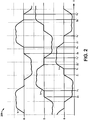
- a plot 200 in Fig. 2 illustrates three motor phase current curves I S , I R , and I T in the motor control system 100 of Fig. 1
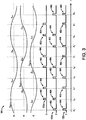
- Fig. 3 shows a plot 300 illustrating three line-to-neutral power source voltage curves V AN , V BN , and V CN , and corresponding switch control signals 122a, 122b, and 122c, respectively, in the system 100 Fig. 1 .
- the exemplary switch control system 124 provides the switching signals 122 as a series or stream of pulses, and in this example, as a series or pulse pairs including a first (leading) pulse 402 and a second (trailing) pulse 404 in each pulse pair, with the first pulse 402 beginning at the firing point (F R , F S , F T , F R ' , F S ', and F T ').
- the pulse pairs are repeated as a series of pulse pairs with the firing angle (the angle between the beginning of the positive portion of the corresponding supply phase voltage waveform and the firing time F) varying in closed-loop fashion according to the output 125a ( Fig. 1 ) from the motor controller 125.
- the transient-based speed estimation system 120a measures the feedback phase current signals 118 (I S , I R , and I T in Fig. 2 ) or the switching device voltages and determines the motor speed ⁇ 'r using the zero-crossing points. In this case, an error signal set is generated and analyzed in the time domain, and a speed-related signal frequency is then produced in the speed estimation system 120a. In the graph 200 of Fig.
- the positive motor current zero-crossings (the times when the corresponding SCR switching devices 110 are turned off) for the phases R, S, and T are indicated as Z R , Z S , and Z T , respectively, and the corresponding zero-crossings associated with the opposite (e.g., negative) current direction are denoted as Z R ', Z S ', and Z T '.
- the firing points for the positive and negative half-cycles are indicated as F R , F S , and F T and F R ', F S ', and F T ', respectively, representing the controlled time at which the SCRs are initially turned on ( e.g., via the leading pulses 402) according to the switching signals 122 from the switch control system 124.
- phase-angle type transient speed-related signals can be derived from measurement of the times Z R , Z S , Z T , Z R ', Z S ', Z T ', F R , F S , F T , F R ', F S ', and F T '.
- a 60 degree detection technique can be used, in which the time differences between two adjacent zero-crossings of the three-phase motor currents is obtained and 1/6 of the supply period T is subtracted to obtain a phase error value.
- phase interval error signals in time units can be developed as (1) Z S '- Z T - T/6, (2) Z R - Z S ' - T/6, (3) Z T ' - Z R - T/6, etc.
- the frequency of the phase error values has been found to be indicative of the rotor speed ⁇ 'r (e.g. , the phase error signal frequency can be correlated to the slip frequency) and the speed estimation system 120a provides the estimate ⁇ 'r accordingly.
- a 180 degree detection may be used, by measuring and computing data points (1) Z R ' - Z R - T/2, (2) Z S ' - Z S - T/2, (3) Z T '- Z T - T/2, etc., wherein the concept of the 180 degree detection may be extended to 360 degree detection, 540 degree detection, 720 degree detection, etc., with higher degrees being preferred in high speed ranges to increase the signal magnitude.
- phase lag signals can be generated for deriving the estimated rotor speed w'r, wherein the speed estimation system 120a measures the time delay between the supply voltage zero-crossings Z V and the shutoff Z on each individual phase ( e.g ., Z R - Z VR , Z S -Z VS , Z T - Z VT , etc.).
- these individual delay values are subtracted from the average delay, and the resulting points create a signal having an AC component indicative of the rotor speed w'r, wherein the average or the DC offset of the signal changes with the firing angle and with changes in the motor load.
- Another transient speed-related signal that can be used by the speed estimation system 120a is a current amplitude signal, wherein the three-phase motor currents I R , I S , and I T of the feedback 118 are sampled at a sampling frequency, and the maximum absolute current value is determined.
- the resulting signal has a large DC component that varies with the firing angle, and which can be removed by taking the difference between the present signal and a past signal, wherein the interval employed between the past and present sample has an impact on the frequency spectrum of the revised current amplitude signal.
- any delay can be used for this DC component removal to obtain a signal with a discernable frequency component indicative of the rotor speed w'r.
- multiples of one sixth the supply period are believed to yield a clear signal under ideal power supply conditions.
- Yet another possible speed-related transient signal can be found in the integral of the motor terminal voltages, such as the integral of the line-to-neutral motor voltages.
- the absolute value of the integral at the end of each SCR conduction period is sampled and used for speed calculation.
- the voltage integral signal includes a DC offset similar to that obtained in the raw current amplitude technique described above, and which may be removed in similar fashion by subtraction from a previous value.
- motor winding voltage can be measured from the feedback 118 during the time when the SCR is off ( e.g ., during the "notch" period). In one implementation, this winding voltage is sampled once during each notch period, preferably at some non-zero time following the zero-crossing when the SCR switching device 110 turns off so as to avoid perturbations caused by operation of snubber circuits or other switching disturbances.
- the absolute value of the motor winding voltages sampled at each notch period of all three phases can be used to determine a speed related signal, from which the rotor speed w'r can be derived, with suitable DC offset removal performed in a manner similar to that described above in connection with the current amplitude signal approach.
- Another speed-related transient signal can be found by measuring the voltage across the switching devices 110 (e.g ., the voltage across the SCRs 110 in one implementation of the switching system 110) during the "notch" period when the device is turned off.
- the amplitudes of these voltage signals vary with a frequency corresponding to the rotor speed ⁇ 'r.
- the notch voltage may be sampled once during each notch period, preferably some non-zero time after the SCR is turned off to avoid measurements during any snubber-related oscillation in the measured voltage signal.
- the absolute values of the notch voltages can be sampled at each notch period of all three phases in one implementation so as to form a signal set to determine the slip speed in the speed estimation system 120a, with any DC component being removed by suitable techniques such as that described above for the current amplitude signal approach.
- the rotor speed w'r can then be easily derived from the slip speed in the speed estimation system 120a.
- Another speed-related transient signal can be derived from the measurements of the phase-to-phase voltage zero crossing times.
- a 180 degree detection technique can be used in which the time differences between two adjacent zero-crossings on each phase is obtained and one half the average supply period T is subtracted to obtain a speed-related signal.
- a speed-related signal can be developed as: (1) Z VA ' - Z VA - T/2, (2) Z VB - Z VB ' - T/2, (3) Z VC ' - Z VC - T/2.
- the frequency of this speed related signal is indicative of rotor speed ⁇ 'r and the speed estimation system 120a provides the estimate w'r accordingly.
- any suitable technique may be used to selectively modify one or more of the switch control signals 122 using the transient excitation system 120b so as to selectively excite/re-excite a motor transient by which the transient-based speed estimation system 120a can derive a rotor speed estimate w'r in reliable fashion across the speed range of interest, even in the presence of power source noise or disturbances.
- any suitable technique may be used to selectively modify one or more of the switch control signals 122 using the transient excitation system 120b so as to selectively excite/re-excite a motor transient by which the transient-based speed estimation system 120a can derive a rotor speed estimate w'r in reliable fashion across the speed range of interest, even in the presence of power source noise or disturbances.
- the motor currents I R , I S , and I T are created by the selective connection of the power source phases A, B, and C to the motor leads R, S, and T by the switching signals 122a, 122b, and 122c from the switch control system 124, where the signals 122 or the generation thereof can be modified using the transient excitation system 120b operatively coupled with the switch control system 124.
- the switch control system 124 provides the switching signals 122 as a series or stream of pulses 402, 404, ( e.g ., Fig.
- pulse pairs provided as pulse pairs with the leading pulse 402 beginning at the firing point (F R , F S , F T , F R ', F S ', and F T '), followed by a trailing pulse 404 to prevent inadvertent (early) SCR shutoff before the actual current zero-crossing.
- the pulse pairs are repeated as a series of pulse pairs with the firing angle being determined according to the closed-loop motor controller output 125a ( Fig. 1 ) from the motor controller 125.
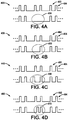
- a first embodiment is shown in a plot 400 in Fig. 4A , in which the transient excitation system 120b operates to selectively inhibit the provision of certain pulses by the switch control system 124, thereby selectively removing individual pulses from the switching control signal 122 to thereby excite the motor transient.
- the excitation system 120b causes removal of a pulse pair in the circled time period 410. This pulse pair removal causes a transient excitation in the motor 104, resulting in excitation or re-excitation of the speed-related motor transient signals, such as those described above or other motor transient that results in a measurable or discernable speed-related signal in the feedback 118.
- Fig. 4A A first embodiment is shown in a plot 400 in Fig. 4A , in which the transient excitation system 120b operates to selectively inhibit the provision of certain pulses by the switch control system 124, thereby selectively removing individual pulses from the switching control signal 122 to thereby excite the motor transient.
- the excitation system 120b causes
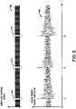
- an exemplary stream of paired firing pulses 122a is shown for a single motor phase R, along with an exemplary phase error signal curve 500 derived from the feedback 118 of the driven motor 104, wherein the selective excitation of the motor transient is done periodically at times T 0 , T 1 , T 2 , etc., by selectively removing a pulse pair 402,404 at portions 410, wherein an excitation period of about 1 Hz is used in this example for a supply frequency of 50 Hz.
- the periodic removal of a firing pulse pair 402,404 causes a noticeable increase in the amplitude of the phase error signal, whereby the invention provides for measurable transient signal strength regardless of power supply disturbance and motor speed, thereby facilitating robust, accurate sensorless speed estimation during the critical motor starting and stopping periods and thereafter as needed.
- the transient excitation need not be periodic.
- the transient excitation system 120b selectively modifies the switch control signal(s) 122 to excite a motor transient at least partially according to an amplitude of the measured transient speed-related signal.
- the system 120b may determine that the transient speed-related signal amplitude has fallen below a predetermined threshold value, and the excitation system 120b accordingly reacts be re-exciting the transient. In this fashion, the excitation may be carried out via the system 120b on an as-needed basis.
- transient excitation example is illustrated in plot 420 of Fig. 4B , wherein the transient excitation system 120b selectively removes one of the two pulses forming a select pulse pair at time 430.
- the system 120b causes removal of the leading pulse 402, although other implementations could involve removal of the trailing pulse 404.
- Other examples are shown in plots 440 and 460 of Figs. 4C and 4D , in which the temporal spacing between the leading and trailing pulses 402 and 404, respectively, is modified ( e.g ., increased or decreased) by the transient excitation system 120b at time periods 450 and 470, respectively.
- the spacings of the leading and trailing pulses 402, 404 of consecutive pulse pairs may be modified (e.g ., increased and decreased) to excite the motor transient.
- this modification may be made according to a modulation waveform, such as a sine wave, a square wave, a triangular sawtooth wave, or other modulation waveform.
- the increase or decrease is done by a relatively small amount of time for the leading pulses 402 to provide an essentially continuous change to the firing angle in one or more of the phases R, S, and/or T.
- the slight modification of consecutive pulses or pulse pairs may mitigate large changes to the firing angle while still causing re-excitation of a measurable speed-related motor transient for speed estimation by the system 120a.
- This selective modification can be done according to a modulation waveform, or alternatively, as a function of the speed signal w'r.
- a gain term may be provided for multiplication with the speed estimate ⁇ 'r to determine the firing angle modification along with a phase shift, wherein the phase shift can also be a function of the frequency of the speed estimate w'r.
- the motor control system 100 of Fig. 1 also includes an optional rotor flux initialization system or component 126, which may be any suitable hardware and/or software operative to selectively initialize rotor flux in the motor 104 during starting prior to activating the transient excitation system 120b.
- the rotor flux initialization system 126 may be adapted to cause the switch control system 124 to selectively activate select ones of the switching devices 110 such that supply voltage is applied to only two of the motor phases R, S, and T for several power cycles to selectively initialize rotor flux to a preset level TH1 126a in the motor 104.
- the initial rotor flux initialization may advantageously improve the initial speed estimation in the low speed range at startup, wherein the inventors have appreciated that certain motor transients may be difficult to measure due to low initial rotor flux values in the motor 104 absent such flux initialization.
- FIG. 6 shows an exemplary startup method 600.
- exemplary method 600 and other methods of the invention are illustrated and described below in the form of a series of acts or events, it will be appreciated that the various methods of the invention are not limited by the illustrated ordering of such acts or events except as specifically set forth herein. In this regard, except as specifically provided hereinafter, some acts or events may occur in different order and/or concurrently with other acts or events apart from those illustrated and described herein, and not all illustrated steps may be required to implement a process or method in accordance with the present invention.
- the illustrated method 600 and other methods of the invention may be implemented in any suitable hardware, software, or combinations thereof, in order to provide improved sensorless motor speed estimation in the control of AC electric motors, although the invention is not limited to the specific applications and implementations illustrated and described herein.
- the method 600 of Fig. 6 begins at 602, with switching signals (e.g ., switch control signals 122 in the system 100 above) being started at 604.
- the switching signals can be provided at 604 and thereafter during startup and/or throughout the motor operation in any suitable fashion, such as by providing a plurality of switch control signals 122 to a switching system 110 for selectively coupling the motor leads R, S, T to an AC power source 106 to control the motor speed according to a desired startup speed profile 128 and according to a rotor speed estimate w'r in the above exemplary system 100.
- Any form of switching signals may be applied, including but not limited to a series or stream of pulses or pairs or other groupings of multiple pulses as exemplified in the above described embodiments or others.
- the method 600 further includes selectively modifying at least one of the switch control signals 122 at 610 to excite transient in a speed related signal, which can be any suitable signal for example, such as a phase error signal, a phase lag signal, a peak current signal, a voltage integral signal, a motor winding voltage signal, a switching device voltage, and a voltage zero crossing signal.
- the selective modification at 610 may take any suitable form that operates to excite a motor transient associated with a speed-related signal.
- pulse-based switch control signals as depicted and described above, several possible examples provide for selectively removing individual pulses from the switching control signal, selectively modifying spacings between select pulses in the switching control signal, selectively removing select pulse pairs from the switching control signal, selectively removing one pulse from select pulse pairs of the switching control signal, selectively modifying spacings between pulses of select pulse pairs in the switching control signal, and/or modifying spacings between pulses of consecutive pulse pairs in the switching control signal to excite the motor transient.
- a speed-related signal associated with the motor transient is measured, and a rotor speed estimate is provided at 614 based at least partially on the measured transient speed-related signal.
- the switches are then controlled at 616 according to the desired speed profile 128 and according to the rotor speed estimate ⁇ 'r.
- a determination is optionally made at 620 as to whether the rotor speed has reached steady state, and if not (NO at 620), the process continues at 610-616 as described above. Otherwise (YES at 620), the motor startup is completed at 622, wherein alternative embodiments may continue the switch control signal provision during steady state operation with continuing speed estimation and transient excitation.
- FIG. 7 Another exemplary motor speed control method 700 is illustrated in Fig. 7 , beginning at 702.
- voltage is applied to a pair of motor windings at 703 to initialize rotor flux in the motor 106 prior to beginning the switching signals at 704 and selectively modifying the switching signal application at 710 for motor transient excitation.
- the method 700 then proceeds generally as in the example of Fig. 6 , with the speed-related signal or signals being measured at 712 and the rotor speed being estimated in accordance therewith at 714.
- the switches are controlled according to the desired speed profile 128 and the estimated rotor speed ⁇ 'r.
- the method 700 further includes determining at 720 whether the rotor speed has reached steady state. If not (NO at 720), the method 700 returns to 710-716 as described above, and otherwise (YES at 620) the motor startup is completed at 722.
- Switching signals are started at 804, such as when the bypass control system 114 in Fig. 1 deactivates the bypass signal 116 to begin controlled motor stopping according to a desired speed profile 128 using the switching system 110 under control of the switching signals 122.
- the switching signals 122 can be provided at 804 and thereafter during stopping in any suitable fashion, for selectively coupling the motor leads R, S, T to the AC power source 106 to control the motor speed according to the desired stopping speed profile 128 and according to the transient-based rotor speed estimate w'r in the system 100.
- any form of switching signals 122 may be applied, including but not limited to a series or stream of pulses or pairs or other groupings of multiple pulses.
- the method 800 further includes selectively modifying at least one of the switch control signals 122 at 810 to excite transient in a speed related signal as described previously for Fig. 6 .
- a speed-related signal associated with the motor transient is measured at 812, and a rotor speed estimate is provided at 814 based at least partially on the measured transient speed-related signal.
- the switches are then controlled at 816 according to the desired speed profile 128 and the rotor speed estimate w'r, and a determination can optionally be made at 820 as to whether the rotor speed has reached zero. If not (NO at 820), the process continues at 810-816 as described above, and if so (YES at 820), the motor stopping is completed at 822.
- the invention discloses AC motor control systems and speed controllers, including a transient-based speed estimation system that provides a rotor speed estimate based on a measured speed-related motor transient signal, and a transient excitation system which selectively modifies at least one switch control signal to excite the measured motor transient.
- the measured speed-related transient may include a phase error signal, a phase lag signal, a peak current signal, a voltage integral signal, a motor winding voltage signal, a switching device voltage, and a voltage zero crossing signal
- the switching signal modification can comprise removal of select pulse(s) from a switching control pulse stream or selective modification of spacings between pulses to re-excite the motor transient.
Landscapes
- Engineering & Computer Science (AREA)
- Power Engineering (AREA)
- Control Of Ac Motors In General (AREA)
- Motor And Converter Starters (AREA)
Claims (10)
- Système de contrôle d'un moteur à courant alternatif CA (100) pour commander un moteur CA asynchrone (104), le système de contrôle moteur comprenant :un système de commutation (110) incluant une pluralité de dispositifs de commutation (110a, 110b, 110c) couplés entre une source d'alimentation CA (106) et un moteur asynchrone (104), les dispositifs de commutation individuels permettant de coupler sélectivement un conducteur correspondant du moteur à la source d'alimentation CA conformément à un signal de contrôle de commutation correspondant (122), le système de commutation fournissant en outre au moins un signal de rétroaction (118) ; etun système de contrôle de vitesse du moteur (120) couplé fonctionnellement au système de commutation et fournissant le signal de contrôle de commutation au système de commutation, le système de contrôle de vitesse du moteur comprenant en outre :un contrôleur moteur (125) fournissant une sortie de contrôleur moteur (125a) pour contrôler la vitesse du moteur durant le démarrage ou la mise à l'arrêt conformément à un profil de vitesse désiré (128) et conformément à une estimation de vitesse du rotor ;un système de contrôle de commutation (124) fournissant une pluralité de signaux de contrôle de commutation (122a, 122b, 122c) pour contrôler l'actionnement des dispositifs de commutation du système de commutation durant le démarrage ou la mise à l'arrêt du moteur conformément à la sortie du contrôleur ;un système d'excitation de réponse transitoire (120b) couplé fonctionnellement au système de contrôle de commutation pour modifier sélectivement au moins un signal de contrôle de commutation afin d'exciter une réponse transitoire du moteur qui provoque au moins un signal transitoire mesurable ou détectable relatif à la vitesse associé à la réponse transitoire du moteur, et qui est fourni dans ledit au moins un signal de rétroaction ; etun système d'estimation de vitesse sur base de réponse transitoire (120a) couplé fonctionnellement au système de commutation, le système d'estimation de vitesse sur base de réponse transitoire effectuant en outrela réception dudit au moins un signal de rétroaction (118) en provenance du système de commutation ; etla mesure dudit au moins un signal transitoire relatif à la vitesse dans ledit au moins un signal de rétroaction, et la génération d'un signal d'erreur de phase sur base de la mesure ;la détermination de l'estimation de vitesse du rotor à partir du signal d'erreur de phase ; etla fourniture de l'estimation de vitesse du rotor au contrôleur moteur.
- Système de contrôle moteur selon la revendication 1, dans lequel le système d'estimation de vitesse sur base de réponse transitoire détermine au moins partiellement l'estimation de vitesse du rotor conformément au signal transitoire relatif à la vitesse, et dans lequel le signal transitoire relatif à la vitesse est un signal parmi un signal de retard de phase, un signal de courant de pointe, un signal d'intégrale de tension, un signal de tension du bobinage moteur, un signal de dispositif de commutation, et un signal de franchissement de tension nulle.
- Système de contrôle moteur selon la revendication 1 ou 2, dans lequel ledit au moins un signal de contrôle de commutation comprend une série d'impulsions pour contrôler un dispositif correspondant parmi les dispositifs de commutation, et dans lequel le système d'excitation de réponse transitoire élimine sélectivement des impulsions individuelles du signal de contrôle de commutation pour exciter la réponse transitoire du moteur.
- Système de contrôle moteur selon la revendication 1 ou 2, dans lequel ledit au moins un signal de contrôle de commutation comprend une série d'impulsions pour contrôler un dispositif correspondant parmi les dispositifs de commutation, et dans lequel le système d'excitation de réponse transitoire modifie sélectivement les espacements entre des impulsions sélectionnées dans le signal de contrôle de commutation pour exciter la réponse transitoire du moteur.
- Système de contrôle moteur selon la revendication 1 ou 2, dans lequel ledit au moins un signal de contrôle de commutation comprend une série de paires d'impulsions pour contrôler un dispositif correspondant parmi les dispositifs de commutation, et dans lequel le système d'excitation de réponse transitoire élimine sélectivement des paires d'impulsions sélectionnées du signal de contrôle de commutation pour exciter la réponse transitoire du moteur.
- Système de contrôle moteur selon la revendication 1 ou 2, dans lequel ledit au moins un signal de contrôle de commutation comprend une série de paires d'impulsions pour contrôler un dispositif correspondant parmi les dispositifs de commutation, et dans lequel le système d'excitation de réponse transitoire élimine sélectivement une impulsion parmi des paires d'impulsions sélectionnées du signal de contrôle de commutation pour exciter la réponse transitoire du moteur.
- Système de contrôle moteur selon la revendication 1, dans lequel ledit au moins un signal de contrôle de commutation comprend une série de paires d'impulsions pour contrôler un dispositif correspondant parmi les dispositifs de commutation, et dans lequel le système d'excitation de réponse transitoire modifie sélectivement les espacements entre les impulsions de paires d'impulsions sélectionnées dans le signal de contrôle de commutation pour exciter la réponse transitoire du moteur.
- Système de contrôle moteur selon la revendication 1 ou 2, dans lequel ledit au moins un signal de contrôle de commutation comprend une série de paires d'impulsions pour contrôler un dispositif correspondant parmi les dispositifs de commutation, et dans lequel le système d'excitation de réponse transitoire modifie sélectivement les espacements entre des impulsions de paires d'impulsions consécutives dans le signal de contrôle de commutation pour exciter la réponse transitoire du moteur.
- Système de contrôle moteur selon la revendication 1 ou 2, comprenant en outre un système d'initialisation de flux de rotor couplé fonctionnellement au système de contrôle de commutation pour initialiser sélectivement un flux de rotor dans le moteur lors du démarrage avant l'activation du système d'excitation de réponse transitoire.
- Procédé de contrôle de la vitesse d'un moteur CA (104) durant le démarrage ou la mise à l'arrêt, le procédé comprenant :la fourniture d'une pluralité de signaux de contrôle de commutation (122a, 122b, 122c) à un système de commutation (110) pour un couplage sélectif de conducteurs du moteur à une source d'alimentation CA (106) afin de contrôler la vitesse du moteur durant le démarrage ou la mise à l'arrêt conformément à un profil de vitesse désiré (128).et conformément à une estimation de vitesse du rotor ;la modification sélective d'au moins un des signaux de contrôle de commutation pour exciter une réponse transitoire du moteur, qui résulte en au moins un signal transitoire mesurable ou détectable relatif à la vitesse associé à la réponse transitoire du moteur, et qui est fourni dans ledit au moins un signal de rétroaction ;la réception par un système de contrôle de vitesse du moteur (120) dudit au moins un signal de rétroaction en provenance du système de commutation ; etla mesure dudit au moins un signal transitoire relatif à la vitesse dans ledit au moins un signal de rétroaction, et la génération d'un signal d'erreur de phase sur base de la mesure ; etla détermination de l'estimation de vitesse du rotor à partir du signal d'erreur de phase ; etla fourniture de l'estimation de vitesse du rotor au contrôleur moteur.
Applications Claiming Priority (1)
| Application Number | Priority Date | Filing Date | Title |
|---|---|---|---|
| US11/379,887 US7227326B1 (en) | 2006-04-24 | 2006-04-24 | System and method for transient-based motor speed estimation with transient excitation |
Publications (3)
| Publication Number | Publication Date |
|---|---|
| EP1850471A2 EP1850471A2 (fr) | 2007-10-31 |
| EP1850471A3 EP1850471A3 (fr) | 2015-08-12 |
| EP1850471B1 true EP1850471B1 (fr) | 2017-06-21 |
Family
ID=38090156
Family Applications (1)
| Application Number | Title | Priority Date | Filing Date |
|---|---|---|---|
| EP07006396.1A Active EP1850471B1 (fr) | 2006-04-24 | 2007-03-28 | Système et procédé d'estimation de la vitesse d'un moteur à excitation transitoire |
Country Status (3)
| Country | Link |
|---|---|
| US (2) | US7227326B1 (fr) |
| EP (1) | EP1850471B1 (fr) |
| CN (1) | CN101064493B (fr) |
Families Citing this family (26)
| Publication number | Priority date | Publication date | Assignee | Title |
|---|---|---|---|---|
| US7345449B2 (en) * | 2005-08-29 | 2008-03-18 | Benshaw, Inc. | Method of rotating a polyphase motor at less than rated speed |
| US7800339B2 (en) * | 2006-11-20 | 2010-09-21 | Honeywell International Inc. | Drive control assembly for controlling a motor |
| US8138709B2 (en) * | 2007-08-31 | 2012-03-20 | Rockwell Automation Technologies, Inc. | Control method and system |
| US8203304B2 (en) * | 2007-08-31 | 2012-06-19 | Rockwell Automation Technologies, Inc. | Control method and system with feedback indicative of load flux |
| IL195102A0 (en) * | 2008-11-04 | 2009-08-03 | Vainer Zvi | Method and device for an induction motor start |
| US8084984B2 (en) * | 2008-12-22 | 2011-12-27 | Eaton Corporation | System and method for monitoring and controlling stator winding temperature in a de-energized AC motor |
| US20110214660A1 (en) * | 2010-03-08 | 2011-09-08 | Gillespie Timothy Andrew | System for monitoring a cooling fan of an appliance |
| US8519662B2 (en) | 2010-05-26 | 2013-08-27 | Rockwell Technologies, Inc. | Method and apparatus for controlling motor torque |
| US8566056B2 (en) * | 2010-06-16 | 2013-10-22 | Eaton Corporation | System and method of speed detection in an AC induction machine |
| US8638059B2 (en) | 2010-08-11 | 2014-01-28 | Dayton-Phoenix Group, Inc. | Control for multi-phase induction motor |
| US8570003B2 (en) | 2011-04-13 | 2013-10-29 | Rockwell Automation Technologies, Inc. | Double fed induction generator converter and method for suppressing transient in deactivation of crowbar circuit for grid fault ridethrough |
| JP5838038B2 (ja) | 2011-04-22 | 2015-12-24 | サンデンホールディングス株式会社 | モータ制御装置 |
| US8587240B2 (en) * | 2011-07-20 | 2013-11-19 | Eaton Corporation | Operationally dependent filtering for soft starter current measurements |
| US9791487B2 (en) * | 2012-03-29 | 2017-10-17 | Egalax_Empia Technology Inc. | Method and device for measuring signals |
| US9502881B2 (en) * | 2012-08-30 | 2016-11-22 | Siemens Aktiengesellschaft | Switchgear for controlling the energy supply of an electric motor connected thereto |
| WO2014075743A1 (fr) * | 2012-11-19 | 2014-05-22 | Siemens Aktiengesellschaft | Appareil de commutation pour la commande de l'alimentation en énergie d'un moteur électrique disposé en aval |
| US20150048690A1 (en) * | 2013-08-15 | 2015-02-19 | Solcon Industries Ltd. | Medium voltage power controller |
| US9160257B2 (en) * | 2013-12-23 | 2015-10-13 | Eaton Corporation | Soft starter system and method of operating same |
| TWI526904B (zh) * | 2013-12-31 | 2016-03-21 | Egalax Empia Technology Inc | Capacitive touch device and its chord wave measurement method |
| TW201547177A (zh) * | 2014-04-25 | 2015-12-16 | Kmt Waterjet Systems Inc | 用於感應馬達之控制系統 |
| US9431949B2 (en) | 2014-04-29 | 2016-08-30 | General Electric Company | Induction motor speed estimation |
| US10056851B2 (en) | 2014-05-30 | 2018-08-21 | Eaton Corporation | System and method for induction motor speed estimation using a soft starter system |
| US9806642B2 (en) * | 2014-11-06 | 2017-10-31 | Rockwell Automation Technologies, Inc. | Modular multiple single-pole electromagnetic switching system and method |
| US9800188B2 (en) * | 2015-09-15 | 2017-10-24 | Regal Beloit America, Inc. | Hybrid drive circuit for variable speed induction motor |
| US11722090B2 (en) | 2021-04-21 | 2023-08-08 | Emerson Electric Co. | Control circuits for compressor motors including multiple capacitors |
| EP4350970A1 (fr) * | 2022-10-07 | 2024-04-10 | dormakaba Deutschland GmbH | Procédé de détermination d'au moins une propriété d'un mouvement de rotation d'une machine triphasée en fonctionnement d'un générateur et entraînement électromécanique |
Family Cites Families (29)
| Publication number | Priority date | Publication date | Assignee | Title |
|---|---|---|---|---|
| US3585486A (en) * | 1969-06-20 | 1971-06-15 | Westinghouse Electric Corp | An electrical converter system employing a control converter for controlling the operation of a power converter |
| US3852654A (en) * | 1972-04-11 | 1974-12-03 | Westinghouse Electric Corp | Cycloconverter system including means to derive a control signal representing fundamental converter output |
| US3965430A (en) * | 1973-12-26 | 1976-06-22 | Burroughs Corporation | Electronic peak sensing digitizer for optical tachometers |
| US4348625A (en) * | 1979-12-21 | 1982-09-07 | Marmon Company | Variable speed motor system |
| US4376970A (en) * | 1980-12-22 | 1983-03-15 | Kearney & Trecker Corporation | High speed digital position monitoring system |
| GB2189910A (en) * | 1986-04-30 | 1987-11-04 | Philips Electronic Associated | Motor speed control system |
| US4864284A (en) * | 1987-12-08 | 1989-09-05 | Caterpillar Inc. | Apparatus for sensing a failed position and velocity sensor |
| JPH04121091A (ja) * | 1990-09-07 | 1992-04-22 | Fanuc Ltd | インダクションモータの駆動方式 |
| US5225749A (en) * | 1990-09-26 | 1993-07-06 | Mitsubishi Denki Kabushiki Kaisha | System for controlling the rotational speed of a rotary member |
| US5245256A (en) * | 1991-02-15 | 1993-09-14 | Seagate Technology, Inc. | Closed loop control of a brushless DC motor at nominal speed |
| US5187419A (en) * | 1991-05-06 | 1993-02-16 | Allen-Bradley Company, Inc. | Electric motor control apparatus and method |
| CA2078903C (fr) * | 1991-12-13 | 1998-08-18 | Gordon Brent Barrus | Mecanisme d'entrainement de ruban d'imprimante |
| KR0153456B1 (ko) * | 1992-08-17 | 1998-12-15 | 강진구 | 단상유도 전동기의 제어방법 |
| US5548197A (en) | 1994-09-28 | 1996-08-20 | Allen-Bradley Company, Inc. | Method and apparatus for determining motor speed using zero crossing times |
| US5631999A (en) * | 1995-09-06 | 1997-05-20 | Seagate Technology Inc. | Adaptive compensation for hard disc drive spindle motor manufacturing tolerances |
| US5744723A (en) * | 1996-05-10 | 1998-04-28 | Csi Technology, Inc. | Method for determining rotational speed from machine vibration data |
| JP3116831B2 (ja) * | 1996-08-08 | 2000-12-11 | 富士電機株式会社 | 誘導電動機の可変速制御装置 |
| DE19843133C2 (de) | 1998-09-21 | 2001-03-15 | Siemens Ag | Verfahren zum Messen der Drehzahl einer Induktionsmaschine und zugehörige Einrichtung |
| JP4475368B2 (ja) * | 2000-03-10 | 2010-06-09 | 富士電機システムズ株式会社 | 速度センサレスベクトル制御装置 |
| US6541928B2 (en) * | 2000-12-29 | 2003-04-01 | Stmicroelectronics, Inc. | Adaptive system and method for spinning a polyphase disk drive motor from a stationary position |
| JP4411796B2 (ja) * | 2001-04-27 | 2010-02-10 | 富士電機システムズ株式会社 | 速度センサを持たない誘導モータドライブの制御システム、オブザーバ及び制御方法 |
| US6864659B2 (en) * | 2001-07-12 | 2005-03-08 | Varidigm Corporation | Variable speed controller for air moving applications using an AC induction motor |
| US6713978B2 (en) * | 2001-07-18 | 2004-03-30 | Texas A&M University System | Method and system for determining induction motor speed |
| US6640196B1 (en) | 2001-08-16 | 2003-10-28 | Reliance Electric Technologies, Llc | System and method for motor fault detection by space vector angular fluctuation |
| US6979970B2 (en) * | 2003-06-30 | 2005-12-27 | Matsushita Electric Industrial Co., Ltd. | Sensorless motor driving device and its driving method |
| US6879124B1 (en) * | 2004-01-07 | 2005-04-12 | Quan Jiang | Method to detect the true zero-crossing points of the phase back EMF for sensorless control of brushless DC motors |
| ATE349102T1 (de) * | 2004-09-09 | 2007-01-15 | Abb Oy | Steuerung ohne geschwindigkeitsfühler einer induktionsmaschine unter verwendung eines pbm- wechselrichters mit lc ausgangsfilter |
| US7164254B2 (en) | 2005-02-28 | 2007-01-16 | Rockwell Automation Technologies, Inc. | Modulation methods and apparatus for reducing common mode voltages |
| US7106025B1 (en) | 2005-02-28 | 2006-09-12 | Rockwell Automation Technologies, Inc. | Cancellation of dead time effects for reducing common mode voltages |
-
2006
- 2006-04-24 US US11/379,887 patent/US7227326B1/en active Active
-
2007
- 2007-03-28 EP EP07006396.1A patent/EP1850471B1/fr active Active
- 2007-04-23 CN CN2007101026117A patent/CN101064493B/zh active Active
- 2007-04-28 US US11/741,728 patent/US7538507B2/en active Active
Non-Patent Citations (1)
| Title |
|---|
| None * |
Also Published As
| Publication number | Publication date |
|---|---|
| US20070247099A1 (en) | 2007-10-25 |
| EP1850471A2 (fr) | 2007-10-31 |
| US7538507B2 (en) | 2009-05-26 |
| EP1850471A3 (fr) | 2015-08-12 |
| US7227326B1 (en) | 2007-06-05 |
| CN101064493B (zh) | 2010-06-02 |
| CN101064493A (zh) | 2007-10-31 |
Similar Documents
| Publication | Publication Date | Title |
|---|---|---|
| EP1850471B1 (fr) | Système et procédé d'estimation de la vitesse d'un moteur à excitation transitoire | |
| Schmidt et al. | Initial rotor angle detection of a nonsalient pole permanent magnet synchronous machine | |
| US9784772B2 (en) | Sensorless rotor angle detection circuit and method for a permanent magnet synchronous machine | |
| US6441572B2 (en) | Detection of rotor angle in a permanent magnet synchronous motor at zero speed | |
| US5448149A (en) | Indirect rotor position sensor for a sinusoidal synchronous reluctance machine | |
| EP3540933B1 (fr) | Procédé d'entraînement d'un moteur sans capteur | |
| MadhusudhanaRao et al. | Speed control of BLDC motor using DSP | |
| EP3261245B1 (fr) | Procédé et circuit électronique pour détection de blocage | |
| US11463033B2 (en) | Apparatus, system, and method for controlling motor | |
| US7224138B2 (en) | Method, system, and program product for feedback control of a target system utilizing imposition of a periodic modulating signal onto a command signal | |
| JP2003180094A (ja) | Pmモータの磁極位置推定方式 | |
| EP1684411A2 (fr) | Commande d'un moteur | |
| KR101448677B1 (ko) | Bldc 모터의 회전자 위치 추정 장치 및 방법 | |
| CN108258950A (zh) | 永磁无刷直流电机驱动起动的控制方法 | |
| Darba et al. | Sensorless commutation and speed control of Brushless DC-machine drives based on the back-EMF symmetric threshold-tracking | |
| EP1806835B1 (fr) | Appareil d excitation de moteur | |
| US20160156294A1 (en) | Motor driving module | |
| Li et al. | A new sensorless control method for brushless permanent magnet DC motors | |
| Raţă et al. | Induction motor speed estimator using rotor slot harmonics | |
| US11705841B2 (en) | Estimation device and AC motor drive device | |
| Hurst et al. | Sensorless speed measurement using current harmonic spectral estimation in induction machine drives | |
| JP4127000B2 (ja) | モータ制御装置 | |
| RU2656846C1 (ru) | Способ подхвата преобразователя частоты | |
| Boughaba et al. | Robust sensorless control of BLDC motor using second derivative function of the sum of terminal voltages | |
| KR20080079142A (ko) | 홀센서가 없는 오디디용 브러시리스 직류전동기의 기동방법 |
Legal Events
| Date | Code | Title | Description |
|---|---|---|---|
| PUAI | Public reference made under article 153(3) epc to a published international application that has entered the european phase |
Free format text: ORIGINAL CODE: 0009012 |
|
| AK | Designated contracting states |
Kind code of ref document: A2 Designated state(s): AT BE BG CH CY CZ DE DK EE ES FI FR GB GR HU IE IS IT LI LT LU LV MC MT NL PL PT RO SE SI SK TR |
|
| AX | Request for extension of the european patent |
Extension state: AL BA HR MK YU |
|
| PUAL | Search report despatched |
Free format text: ORIGINAL CODE: 0009013 |
|
| AK | Designated contracting states |
Kind code of ref document: A3 Designated state(s): AT BE BG CH CY CZ DE DK EE ES FI FR GB GR HU IE IS IT LI LT LU LV MC MT NL PL PT RO SE SI SK TR |
|
| AX | Request for extension of the european patent |
Extension state: AL BA HR MK RS |
|
| RIC1 | Information provided on ipc code assigned before grant |
Ipc: H02P 6/18 20060101ALI20150706BHEP Ipc: H02P 23/00 20060101AFI20150706BHEP |
|
| 17P | Request for examination filed |
Effective date: 20160127 |
|
| RBV | Designated contracting states (corrected) |
Designated state(s): AT BE BG CH CY CZ DE DK EE ES FI FR GB GR HU IE IS IT LI LT LU LV MC MT NL PL PT RO SE SI SK TR |
|
| AKX | Designation fees paid |
Designated state(s): DE FR GB |
|
| AXX | Extension fees paid |
Extension state: HR Extension state: RS Extension state: MK Extension state: BA Extension state: AL |
|
| GRAP | Despatch of communication of intention to grant a patent |
Free format text: ORIGINAL CODE: EPIDOSNIGR1 |
|
| RIC1 | Information provided on ipc code assigned before grant |
Ipc: H02P 23/00 20160101AFI20170303BHEP Ipc: H02P 6/18 20160101ALI20170303BHEP |
|
| INTG | Intention to grant announced |
Effective date: 20170322 |
|
| RIN1 | Information on inventor provided before grant (corrected) |
Inventor name: MESSERSMITH, DAVID M. Inventor name: LU, HAIHUI Inventor name: NONDAHL, THOMAS A. |
|
| GRAS | Grant fee paid |
Free format text: ORIGINAL CODE: EPIDOSNIGR3 |
|
| GRAA | (expected) grant |
Free format text: ORIGINAL CODE: 0009210 |
|
| AK | Designated contracting states |
Kind code of ref document: B1 Designated state(s): DE FR GB |
|
| REG | Reference to a national code |
Ref country code: GB Ref legal event code: FG4D |
|
| REG | Reference to a national code |
Ref country code: DE Ref legal event code: R096 Ref document number: 602007051373 Country of ref document: DE |
|
| REG | Reference to a national code |
Ref country code: DE Ref legal event code: R097 Ref document number: 602007051373 Country of ref document: DE |
|
| REG | Reference to a national code |
Ref country code: FR Ref legal event code: PLFP Year of fee payment: 12 |
|
| PLBE | No opposition filed within time limit |
Free format text: ORIGINAL CODE: 0009261 |
|
| STAA | Information on the status of an ep patent application or granted ep patent |
Free format text: STATUS: NO OPPOSITION FILED WITHIN TIME LIMIT |
|
| 26N | No opposition filed |
Effective date: 20180322 |
|
| PGFP | Annual fee paid to national office [announced via postgrant information from national office to epo] |
Ref country code: FR Payment date: 20230222 Year of fee payment: 17 |
|
| PGFP | Annual fee paid to national office [announced via postgrant information from national office to epo] |
Ref country code: GB Payment date: 20230221 Year of fee payment: 17 Ref country code: DE Payment date: 20230221 Year of fee payment: 17 |
|
| P01 | Opt-out of the competence of the unified patent court (upc) registered |
Effective date: 20230404 |