EP1850452A1 - Core, rotor, motor, and compressor - Google Patents
Core, rotor, motor, and compressor Download PDFInfo
- Publication number
- EP1850452A1 EP1850452A1 EP06712383A EP06712383A EP1850452A1 EP 1850452 A1 EP1850452 A1 EP 1850452A1 EP 06712383 A EP06712383 A EP 06712383A EP 06712383 A EP06712383 A EP 06712383A EP 1850452 A1 EP1850452 A1 EP 1850452A1
- Authority
- EP
- European Patent Office
- Prior art keywords
- predetermined direction
- magnet
- rotor
- core
- magnets
- Prior art date
- Legal status (The legal status is an assumption and is not a legal conclusion. Google has not performed a legal analysis and makes no representation as to the accuracy of the status listed.)
- Withdrawn
Links
- 239000000696 magnetic material Substances 0.000 claims abstract description 40
- 230000000994 depressogenic effect Effects 0.000 claims description 13
- 230000008878 coupling Effects 0.000 claims description 11
- 238000010168 coupling process Methods 0.000 claims description 11
- 238000005859 coupling reaction Methods 0.000 claims description 11
- 230000000149 penetrating effect Effects 0.000 claims 2
- 230000004907 flux Effects 0.000 abstract description 79
- 230000009467 reduction Effects 0.000 description 6
- 230000000694 effects Effects 0.000 description 5
- 229910000831 Steel Inorganic materials 0.000 description 3
- 239000010959 steel Substances 0.000 description 3
- 230000006835 compression Effects 0.000 description 2
- 238000007906 compression Methods 0.000 description 2
- 239000000470 constituent Substances 0.000 description 2
- 239000003507 refrigerant Substances 0.000 description 2
- 239000000853 adhesive Substances 0.000 description 1
- 230000015572 biosynthetic process Effects 0.000 description 1
- 230000007423 decrease Effects 0.000 description 1
- 239000000428 dust Substances 0.000 description 1
- 230000010354 integration Effects 0.000 description 1
- 238000000034 method Methods 0.000 description 1
- 230000004048 modification Effects 0.000 description 1
- 238000012986 modification Methods 0.000 description 1
- 230000002093 peripheral effect Effects 0.000 description 1
- 229910052761 rare earth metal Inorganic materials 0.000 description 1
- 150000002910 rare earth metals Chemical class 0.000 description 1
- 125000006850 spacer group Chemical group 0.000 description 1
- 238000004804 winding Methods 0.000 description 1
Images










Classifications
-
- H—ELECTRICITY
- H02—GENERATION; CONVERSION OR DISTRIBUTION OF ELECTRIC POWER
- H02K—DYNAMO-ELECTRIC MACHINES
- H02K1/00—Details of the magnetic circuit
- H02K1/06—Details of the magnetic circuit characterised by the shape, form or construction
- H02K1/22—Rotating parts of the magnetic circuit
- H02K1/27—Rotor cores with permanent magnets
- H02K1/2706—Inner rotors
- H02K1/272—Inner rotors the magnetisation axis of the magnets being perpendicular to the rotor axis
- H02K1/274—Inner rotors the magnetisation axis of the magnets being perpendicular to the rotor axis the rotor consisting of two or more circumferentially positioned magnets
- H02K1/2753—Inner rotors the magnetisation axis of the magnets being perpendicular to the rotor axis the rotor consisting of two or more circumferentially positioned magnets the rotor consisting of magnets or groups of magnets arranged with alternating polarity
- H02K1/276—Magnets embedded in the magnetic core, e.g. interior permanent magnets [IPM]
-
- H—ELECTRICITY
- H02—GENERATION; CONVERSION OR DISTRIBUTION OF ELECTRIC POWER
- H02K—DYNAMO-ELECTRIC MACHINES
- H02K1/00—Details of the magnetic circuit
- H02K1/06—Details of the magnetic circuit characterised by the shape, form or construction
- H02K1/22—Rotating parts of the magnetic circuit
- H02K1/27—Rotor cores with permanent magnets
Definitions
- the present invention relates to a core, a rotor, a motor and a compressor, and, more specifically, to relative positions of a magnet and a core holding the magnet buried therein.
- Permanent magnet motors are classified for example into a rotating armature type with a permanent magnet arranged on the side of a stator, and a rotating field type with a permanent magnet arranged on the side of a rotor.
- a motor of the rotating field type linkage of magnetic flux generated by a permanent magnet (hereinafter referred to as a "magnet") of a rotor with a coil on the side of a stator is generated to thereby rotate the rotor.
- a particular structure of a rotor of the rotating field motor is such that a magnet is buried in a core that extends in a direction of a rotation axis, and a pole face of the magnet extends in the direction of the rotation axis.
- an end of a magnet defined in a direction of a rotation axis is depressed or flat with respect to an end of a core defined in the same direction. This causes magnetic flux generated by the magnet to be short-circuited from one pole face to another pole face of the same magnet by passing through the end of the magnet.
- Figs. 31 and 32 show a short circuit of magnetic flux generated in a conventional rotor by magnetic lines of force.
- an end of a magnet is depressed with respect to an end of a core.
- an end of a magnet is flat with respect to an end of a core.
- the present invention has been made in view of the above-discussed circumstances.
- the present invention is intended to prevent a short circuit of magnetic flux in a rotor.
- the rotor comprises: a core (11) extending in a predetermined direction (91); and a magnet (21) buried in the core and having pole faces (211, 212) extending in the predetermined direction.
- the core has a first part (111; 112) formed by a magnetic material and facing one of the pole faces (211; 212). At least one of ends (21a; 21a) of the magnet defined in the predetermined direction protrudes forward in the predetermined direction with respect to an end (111a; 112a) of the first part, the end of the first part being on the same side with the at least one of the ends of the magnet.
- both of the ends (21a; 21b) of the magnet protrude forward with respect to the ends (112a, 112b) of the first part (112), the ends of the first part being on the same sides with corresponding ones of the ends of the magnet.
- a length (Lm) of the magnet in the predetermined direction (91) satisfies a ratio (Lm / Lo) not more than 1.075 to a length (Lo) of the first part in the predetermined direction.
- the ends (111a, 111b; 112a, 112b) of the first part (111; 112) have recesses (111c, 11d; 112c, 112d) for exposing the ends (21a, 21b) of the magnet (21).
- the core (11) further has a second part (112; 111) formed by a magnetic material and facing another one of the pole faces (212; 211). At least one of the ends (21a; 21a) of the magnet protrudes forward in the predetermined direction (91) with respect to an end (112a; 111a) of the second part, the end of the second part being on the same side with the at least one of the ends of the magnet.
- the ends (112a, 112b; 111a, 111b) of the second part (112; 111) have recesses (111c 111d; 112c, 112d) for exposing the ends (21a, 21b) of the magnet (21).
- the magnet (21) in any one of the first through fifth aspects of the rotor, includes a plurality of magnets arranged in a loop.
- the core (11) further has a third part (113) formed by a magnetic material and arranged between adjacent ones of the magnets (21). At least one of ends (113a; 113b) of the third part defined in the predetermined direction (91) protrudes forward in the predetermined direction with respect to the ends (21a; 21b) of the adjacent ones of the magnets (21), the ends of the adjacent ones of the magnets being on the same side with at least one of ends of the third part.
- the magnet (21) in any one of the first through fifth aspects of the rotor, includes a plurality of magnets arranged in a loop.
- the core (11) further has a third part (113) formed by a magnetic material and arranged between adjacent ones of the magnets (21). At least one of ends (113a; 113b) of the third part defined in the predetermined direction (91) is depressed in the predetermined direction with respect to the ends (21a; 21b) of the adjacent ones of the magnets (21), the ends of the adjacent ones of the magnets being on the same side with at least one of the ends of the third part.
- the rotor comprises any two or more of the rotors (1e, 1f; 1d, 1d; 1g, 1h) as recited in the first through seventh aspects coupled together in the predetermined direction (91).
- the magnet (21, 25; 21, 21; 21, 25) protrudes forward with respect to the part (111, 112, 121, 122; 111, 112, 111, 112; 111, 112, 121, 122) of the core on the side of at least one of ends of the rotors defined in the predetermined direction, the at least one of the ends having no coupling to another end.
- the rotor comprises any two or more of the rotors (1e, 1f) as recited in the first through seventh aspects coupled together in the predetermined direction (91).
- the part (111, 112, 121, 122) of the core has a recess (111d, 112d, 121d, 122d) for exposing the end (21a, 25a) of the magnet (21, 25) on the side of at least one of ends of the rotors coupling to each other, the at least one of the ends being defined in the predetermined direction.
- the two or more of the rotors (1d, 1d) are coupled through a non-magnetic material (3).
- the rotor comprises: a core (11) having a hole (41) and a cavity (42), the core extending in a predetermined direction (91); and at least two magnets (21, 25) having pole faces (211, 212; 251, 252).
- the hole penetrates the core through the cavity in the predetermined direction from one end (11a) to another end (11b) of the core.
- the cavity has a cross-sectional area to the predetermined direction that is greater than that of the hole to the predetermined direction.
- a first one of the magnets (21; 25) is inserted into the hole, the pole faces (211, 212; 251, 252) of the first one of the magnets extending in the predetermined direction.
- a second one of the magnets (25; 21) is inserted into the hole on the side opposite to the first one of the magnets with respect to the cavity, the pole faces (251, 252; 211, 212) of the second one of the magnets extending in the predetermined direction.
- An end (21b, 25b) of at least one of the magnets respect to the predetermined direction protrudes into the cavity.
- At least one of the magnets (21; 25) has an end (21a, 25a) in the predetermined direction (91) that protrudes forward with respect to the end (11a, 11b) of the core (11).
- the two or more of the rotors (1g, 1h) include a first rotor (1g) and a second rotor (1h).
- a normal direction (21d) to the pole face (212) of the magnet (21) of the first rotor is tilted from a normal direction (25d) to the pole face (251) of the magnet (25) of the second rotor.
- a fourteenth aspect of a rotor of the present invention in the thirteenth aspect of the rotor, in a first projection formed by protruding the magnet (21) of the first rotor (1g) onto a predetermined plane perpendicular to the predetermined direction (91) and in a second projection formed by protruding the magnet (25) of the second rotor (1h) onto the predetermined plane perpendicular to the predetermined direction, an outer edge (212e) of the first projection and an inner edge (251e) of the second projection do not intersect with each other, while an inner edge (211e) of the first projection and an outer edge (252e) of the second projection do not intersect with each other.
- the first rotor (1g) and the second rotor (1h) both have holes (214, 254) into which the magnets (21, 25) are buried.
- the first rotor and the second rotor are coupled to each other through a magnetic plate (7).
- the magnetic plate has a through hole (71).
- the through hole penetrates the magnetic plate in the predetermined direction in an area (222s), the area including projections (214s, 254s) formed by protruding the hole of the first rotor and the hole of the second rotor onto the magnetic to the predetermined direction (91), the area extending from one to the other of the projections.
- a thickness (t) of the magnetic plate is greater at least than either the thickness of the magnet of the first rotor or the thickness of the magnet of the second rotor.
- a seventeenth aspect of a rotor of the present invention in the fifteenth or sixteenth aspect of the rotor, at least either the magnet (21) of the first rotor (1g) or the magnet (25) of the second rotor (1h) protrudes into the through hole (71).
- the rotor has a cavity (45), and first and second holes (43, 44).
- the rotor comprises: a core (11) extending in a predetermined direction (91); and first and second magnets (21; 25) having pole faces (211, 212; 251, 252).
- the first hole extends in the predetermined direction from an end (11a) of the core defined in the predetermined direction to communicate with the cavity.
- the second hole extends in the predetermined direction from another end of the core defined in the predetermined direction to communicate with the cavity.
- the cross section of the cavity taken to the predetermined direction includes both first and second projections (214s, 254s) formed by protruding the first and second holes defined in the predetermined direction.
- the cross section has an area greater than those of both the first and second holes defined in the predetermined direction.
- the first magnet is inserted into the first hole, the pole faces of the first magnet extending in the predetermined direction.
- the second magnet is inserted into the second hole, the pole faces of the second magnet extending in the predetermined direction.
- an outer edge (214s2) of the first projection (214s) and an inner edge (254s1) of the second projection (254s) do not intersect with each other, while an inner edge (214s1) of the first projection and an outer edge (254s2) of the second projection do not intersect with each other.
- the core (11) has a first gap (41; 41) and a second gap (43; 411) both extending in the predetermined direction (91).
- the first gap extends in a first direction (95; 95) perpendicular to the predetermined direction, the first gap holding the magnet (21; 21) buried therein.
- the second gap is defined at an end (41a; 41b) of the first gap in the first direction, the second gap extending in a second direction (93; 95) perpendicular to the predetermined direction.
- a width of the second gap (Wa1; Wa2) defined in a direction (94; 96) perpendicular to both of the predetermined direction and the second direction is greater than a distance (M; M) between the pole faces (211, 212; 211, 212) of the magnet.
- the motor comprises: the rotor (1a to 1d, 2a to 2c) as recited in any one of the first through twentieth aspects, the rotor rotating about a rotation axis (92) extending in the predetermined direction (91); and a stator (51) arranged coaxially with the rotor and facing the rotor.
- a height (d) of the magnet (21) from the end (111b) of the core (111) taken along the rotation axis (92) is smaller than a distance (M) between the pole faces (212, 212) of the same magnet (21), the end of the core being on the side opposite to the stator (51) with respect to the magnet.
- a distance (M) between the pole faces (211, 212) of the same magnet (21) is greater than a distance (A) between a side surface of the rotor (1a) and a surface of the stator (51) facing the side surface.
- a compressor according to the present invention comprises the motor (5) as recited in any one of the first through third aspects.
- the core has first and second parts (111, 112) formed by magnetic materials, the first and second parts both extending in a predetermined direction (91).
- the first and second parts face each other through a gap (41) extending in the predetermined direction.
- At least one of ends (111a; 112a) of the first part (111; 112) defined in the predetermined direction protrudes forward in the predetermined direction with respect to an end (112a; 111a) of the second part, the end of the second part being on the same side with the at least one of the ends of the first part.
- an end of the gap (41) defined in the predetermined direction (91) extends toward the second part (112; 111).
- the core has first and second parts (111, 112) formed by magnetic materials, the first and second parts both extending in a predetermined direction (91).
- the first and second parts face each other through a gap (41) extending in the predetermined direction.
- An end of the gap (41) defined in the predetermined direction (91) extends toward the first and second parts.
- the core further comprises: two or more of the first parts (112); and a plurality of third parts (113) formed by magnetic materials, the third parts extending in the predetermined direction.
- the first parts (112) and the plurality of third parts are alternately arranged in a loop around the second part (111). At least one of ends (113a;113b) of the third part in the predetermined direction protrudes forward in the predetermined direction with respect to the end (112a;112b) of the second part, the end of the second part being on the same side with the at least one of the ends of the third part.
- the core further comprises: two or more of the first parts (112); and a plurality of third parts (113) formed by magnetic materials, the third parts extending in the predetermined direction.
- the first parts (112) and the plurality of third parts are alternately arranged in a loop around the second part (111). At least one of ends (113a;113b) of the third part in the predetermined direction is depressed in the predetermined direction with respect to the end (111a; 111b) of the first part, the end of first second part being on the same side with the at least one of the ends of the third part.
- the core extends in a predetermined direction (91), and comprises a hole (41) and a cavity (42).
- the hole penetrates the core through the cavity in the predetermined direction from one end (11a) to another end (11b) of the core.
- the cavity has a cross-sectional area to the predetermined direction that is greater than that of the hole in the plane perpendicular to the predetermined direction.
- the core extends in a predetermined direction (91).
- the core comprises a cavity (45); a first hole (43) extending in the predetermined direction from one end (11a) of the core to protrude into the cavity; and a second hole (44) extending in the predetermined direction from another end (11b) of the core to protrude into the cavity.
- the cross section of the cavity to the predetermined direction includes both first and second projections (43s, 44s) formed by protruding the first and second holes defined in the predetermined direction.
- the cross section having an area greater than those of both the first and second holes defined in the predetermined direction.
- an outer edge (43s2) of the first projection (43s) and an inner edge (44s1) of the second projection (44s) do not intersect with each other, while an inner edge (43s1) of the first projection and an outer edge (44s2) of the second projection do not intersect with each other.
- magnetic resistance at the protruding end of the magnet is increased.
- magnetic flux is unlikely to be short-circuited from one pole face to another pole face of the same magnet by passing through the end of this magnet.
- the amount of magnetic flux flowing into the stator increases.
- a part of the end of the first part is aligned in the predetermined direction with the end of the magnet.
- the fourth aspect of the rotor of the present invention especially when the magnet protrudes forward with respect to both the first and second parts on the side of at least one end of the core, magnetic resistance at the protruding end of the magnet is increased. Thus magnetic flux is unlikely to be short-circuited from one pole face to another pole face of the same magnet by passing through the end of this magnet.
- a part of the end of the second part is aligned in the predetermined direction with the end of the magnet.
- magnetic saturation in the third part is prevented to thereby prevent the reduction of reluctance torque.
- magnetic flux is unlikely to be short-circuited at the depression from one pole face to another pole face of the same magnet.
- the eighth aspect of the rotor of the present invention magnetic resistance at the protruding end of the magnet is increased.
- magnetic flux is unlikely to be short-circuited from one pole face to another pole face of the same magnet by passing through the end of this magnet.
- the rotor is made by independently forming a plurality of rotors.
- step skew can be defined between a magnet of one rotor and a magnet of another rotor.
- the rotor is made by independently forming a plurality of rotors.
- step skew can be defined between a magnet of one rotor and a magnet of another rotor.
- the core has the recess for exposing the end of the magnet on the side where the rotors are coupled.
- a non-magnetic material is present at the end of the magnet.
- magnetic flux is unlikely to be short-circuited from one pole face to another pole face of the same protruding magnet by passing between the magnets, even when the magnets of the rotors are not in contact with each other at the time of coupling between the rotors.
- the eleventh aspect of the rotor of the present invention even when the magnets inserted into the holes are not in contact with each other, an end of at least one of the magnets protrudes into the cavity. Thus magnetic flux is unlikely to be short-circuited from one pole face to another pole face of this magnet by passing between the magnets.
- At least one of the magnets has an end that protrudes forward with respect to the end of the core.
- magnetic resistance at the protruding end is increased, by which magnetic flux is unlikely to be short-circuited from one pole face to another pole face of the same magnet by passing through the end of this magnet.
- step skew of the magnets of the first and second rotors is defined to thereby reduce torque ripple.
- no magnetic material is held between the pole face of the magnet of the first rotor and the pole face of the magnet of the second rotor. This prevents a short circuit of magnetic flux from one pole face to another pole face that are opposite in polarity and belong to the different magnets.
- step skew is defined between the magnet of the first rotor and the magnet of the second rotor.
- the through hole provides a gap equal to or greater than the respective depths of these magnets in the circumferential direction of the magnetic plate. Thus magnetic flux is unlikely to be short-circuited at the through hole in the circumferential direction of the magnetic plate.
- the magnetic material at this position is spaced apart by the presence of the through hole in the predetermined direction by the thickness of the magnetic plate. Further, the thickness of the magnetic plate is greater than either the thickness of the magnet of the first rotor or that of the magnet of the second rotor. As a result, a short circuit of magnetic flux does not occur between these pole faces by using the through hole as a flux path.
- the seventeenth aspect of the rotor of the present invention even when the magnet of the first rotor and the magnet of the second rotor are not in contact with each other, magnetic flux is unlikely to be short-circuited from one pole face to another pole face of the same protruding magnet by passing through the end of this magnet.
- step skew can be defined between the first and second magnets. Further, as a result of the presence of the cavity, magnetic flux is unlikely to be short-circuited from one pole face to another pole face of the same magnet by passing through the end of this magnet, even when the first and second magnets are not in contact with each other.
- no magnetic material is held between the pole face of the first magnet and that of the second magnet. This prevents a short circuit of magnetic flux from one pole face to another pole face that are opposite in polarity and belong to the different magnets.
- magnetic flux is unlikely to be short-circuited from one pole face to another pole face of the same magnet by passing through the second gap at the end of the magnet close to the second gap.
- the drive efficiency and drive output of the motor are improved.
- magnetic flux is unlikely to be short-circuited from the pole face on the side opposite to the stator to the pole face on the side of the stator by passing through the end of the magnet.
- magnetic flux is unlikely to be short-circuited from the pole face on the side of the stator to the pole face on the side opposite to the stator by passing through the end of the magnet. Namely, magnetic flux flows into the stator in large quantities
- the compressor of the present invention realizes effective compression for example of a refrigerant.
- an end of the magnet defined in the predetermined direction is located between the ends of the first and second parts in the predetermined direction.
- a recess for exposing an end of this magnet is formed at the end of the second part.
- a part of the end of the second part is aligned in the predetermined direction with the end of the magnet.
- the core of the present invention in a rotor formed by inserting a magnet into the gap, recesses for exposing an end of this magnet are formed at the ends of the first and second parts.
- recesses for exposing an end of this magnet are formed at the ends of the first and second parts.
- the reduction of reluctance torque is prevented when the end of the third part in the predetermined direction protrudes forward in the predetermined direction with respect to an end of the magnet.
- the sixth aspect of the core of the present invention in a rotor formed by inserting magnets into the hole from both ends of the core, at least one of the magnets protrudes into the cavity.
- step skew can be defined between these magnets. Further, as a result of the presence of the cavity, magnetic flux is unlikely to be short-circuited from one pole face to another pole face of the same magnet by passing through the end of this magnet, even when the magnets are not in contact with each other.
- the eighth aspect of the core of the present invention when first and second magnets are respectively inserted into the first and second holes, no magnetic material is held between the pole face of the first magnet and the pole face of the second magnet. This prevents a short circuit of magnetic flux from one pole face to another pole face that are opposite in polarity and belong to the different magnets.
- Fig. 1 is a perspective view conceptually showing a rotor 1a according to a first embodiment.
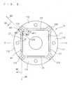
- Fig. 2 is a top view of the rotor 1a viewed in a predetermined direction 91.
- Fig. 3 shows a cross section of the rotor 1a at a position C-C.
- the rotor 1a comprises a core 11 extending in the predetermined direction 91, and a plurality of magnets 21.
- the core has parts 111 to 113 formed by magnetic materials and extending in the predetermined direction 91, wherein the parts 112 and 113 are respectively provided more one.
- magnetic steel sheets are stacked and bolts are put through all holes 8 shown in Fig. 1. Then at least one side of each bolt is fastened by a nut or a rivet pin. In Fig. 3, the holes 8 are indicated by dashed lines.
- the parts 112 and 113 are alternately arranged in a loop around the part 111.
- the parts 112 face the part 111 through gaps 41.
- the magnets 21 are buried in the gaps 41, and arranged in the form of a loop in the core 11.
- the magnets 21 each have pole faces 211 and 212 extending in the predetermined direction 91.
- the magnets 21 each have exposed ends 21a and 21b defined in the predetermined direction 91.
- the parts 111 to 113 are described as follows in terms of the relations with the magnets 21. That is, the part 111 is arranged to face the pole faces 211; and the parts 112 are arranged to face the pole faces 212. The parts 113 are arranged between adj acent ones of the magnets 21.
- the rotor 1a is applied for example to a motor with a stator, and rotates about a rotation axis 92 extending in the predetermined direction 91.
- a stator (not shown) is arranged coaxially with the rotor 1a and faces the rotor 1a. More specifically, the stator is arranged to face the outer peripheral surface of the rotor 1a.
- the part 111 is arranged to face the pole faces 211 on the side opposite to the stator with respect to the magnets 21.
- the parts 112 and 113 are alternately arranged in the form of a loop on the same side with the stator with respect to the magnets 21.
- each of the magnets 21 at least either the end 21a or 21b of the magnet 21 protrudes forward in the predetermined direction 91 with respect to an end 111a or an end 111b of the part 111 that are respectively on the same sides with the ends 21a and 21b.
- both the ends 21a and 21b of the magnet are particularly shown to protrude forward in the predetermined direction 91 with respect to the part 111.
- magnetic resistance at the protruding ends 21a and 21b of the magnet 21 is increased.
- magnetic flux is unlikely to be short-circuited from either one of the pole faces 211 and 212 of the same magnet 21 to the other thereof by passing through the ends 21a and 21b of this magnet 21.
- Fig. 4 shows magnetic flux flowing in the rotor 1a discussed above by magnetic lines of force.
- the magnetic flux generated in the magnet 21 flows from the part 111, passing through the magnet 21 and the part 112, and then flows into a stator 51 without causing a short circuit even in the end 21a of the magnet 21.
- each of the magnets 21 at least either the end 21a or 21b of the magnet 21 may protrude forward in the predetermined direction 91 with respect to an end 112a or an end 112b of the part 112 that are respectively on the same sides with the ends 21a and 21b.
- both the ends 21a and 21b of the magnet 21 are particularly shown to protrude forward in the predetermined direction 91 with respect to the part 112. This aspect produces the same effect as that discussed above.
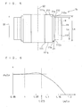
- Fig. 6 shows variations in a magnetic flux quantum relative to a ratio Lm/Lo where Lm is a length of the magnet 21 in the predetermined direction 91 and Lo is the length of the part 112 in the predetermined direction 91.
- Lm is a length of the magnet 21 in the predetermined direction 91
- Lo is the length of the part 112 in the predetermined direction 91.
- a quantum ⁇ a/Lm is applied that indicates a quantum of magnetic flux ⁇ a flowing into a stator per unit length of the magnet 21.
- the ratios Lm/Lo lower than 1, equal to 1 and higher than 1 respectively indicate the cases where both the ends 21a and 21b of the magnet 21 are depressed, flat and protrude forward with respect to the ends 112a and 112 of the part 112 that are respectively on the same sides with the ends 21a and 21b.
- the quantum ⁇ a/Lm increases with the increase of the ratio Lm/Lo from 0.95. The reason therefor is considered that a short circuit of magnetic flux is prevented in the ends 21a and 21b of the magnet 21.
- the quantum ⁇ a/Lm decreases with the increase of the ratio Lm/Lo from around 1.05. The reason therefor is considered that a considerable degree of protrusion of the magnet 21 results in a short circuit of magnetic flux.
- the quantum ⁇ a/Lm is the same as or higher than this reference value when the ratio Lm/Lo is not smaller than 1 and not higher than 1.075. That is, the amount of magnetic flux flowing into a stator increases.
- a rotor 1c shown in Fig. 7 produces the same effect as that discussed above. Namely, in the stator 1c, the end 21a of the magnet 21 protrudes forward in the predetermined direction 91 with respect to the end 111a of the part 111 that is on the same side with the end 21a. The end 21b of the magnet 21 protrudes forward in the predetermined direction 91 with respect to the end 112b of the part 112 that is on the same side with the end 21b.
- Fig.8 conceptually shows a cross section of a rotor 1d according to a second embodiment.
- the rotor 1d at least either the end 21a or 21b of the magnet 21 protrudes forward in the predetermined direction 91 with respect to both the end 111a and 111b of the part 111 and the end 112a and 112b of the part 112 that are on the same side with the end 21a or 21b.
- both the ends 21a and 21b of the magnet are particularly shown to protrude forward with respect to the parts 111 and 112.
- magnetic resistance at the protruding end 21a or 21b of the magnet 21 is increased to a greater degree.
- magnetic flux is unlikely to be short-circuited from either one of the pole faces 211 and 212 of the same magnet 21 to the other thereof by passing through the ends 21a and 21b of this magnet 21.
- Fig. 9 shows magnetic flux flowing in the rotor 1d by magnetic lines of force.
- the magnetic flux generated in the magnet 21 flows from the part 111, passing through the magnet 21 and the part 112, and then flows into the stator 51 without causing a short circuit even in the end 21a of the magnet 21.
- At least one of the ends 113a and 113b of the part 113 in the predetermined direction 91 desirably protrudes forward in the predetermined direction 91 with respect to the ends 21a or 21b of the magnets 21 adjacent to each other with this part 113 held therebetween, where these ends 21a and 21b are respectively on the same sides with the ends 113a and 113b.
- This aspect is shown for example in Fig. 1.
- the end 113b is on the side opposite to the 113a of the part 113:
- magnetic saturation in the part 113 is prevented to thereby prevent the reduction of reluctance torque.
- At least either the end 113a or 113b of the part 113 is also desirably depressed in the predetermined direction 91 with respect to the ends 21a or 21b of the magnets 21 adjacent to each other with this part 113 held therebetween, where these ends 21a and 21b are respectively on the same sides with the ends 113a and 113b.
- the reason therefor is that magnetic flux is unlikely to be short-circuited from one of the pole faces 211 and 212 of the same magnet 21 to the other thereof.
- This example is desirable especially in a situation where the part 113 has a gap 43 communicating to the gap 41, and the width of this gap 43 is smaller than a distance between the pole faces 211 and 212 of the same magnet 21 as shown in Fig. 2. This is because, although a short circuit is likely to occur in this case from either one of the pole faces 211 and 212 of the same magnet 21 to the other thereof through this gap, a short circuit of magnetic flux is less likely at the depression of the part 113 formed by defining the part 113 at a lower level than the magnet 21.
- a distance Wa1 between the parts 112 and 113 that is interpreted as the width of the gap 43 is desirably greater than a distance M between the pole faces 121 and 122 of the magnet 21 (Fig. 2).
- the first gap 41 extends in a direction 95 perpendicular to the predetermined direction 91, and holds the magnet 21 buried therein.
- the second gap 43 is defined at an end 41a of the first gap 41 in the direction 95, and extends in a direction 93 perpendicular to the predetermined direction 91.
- the width Wa1 of the second gap 43 in a direction 94 perpendicular to both of the predetermined direction 91 and the direction 93 is greater than the distance M between the pole faces 211 and 212 of the magnet 21.
- a distance Wa2 between the parts 111 and 112 considered as the width of a gap 411 as part of the gap 41 defined between the end 41a and the end 42b is desirably greater than the distance M between the pole faces 121 and 122 of the magnet 21 (Fig. 2).
- the first gap 41 extends in the direction 95 perpendicular to the predetermined direction 91, and holds the magnet 21 buried therein.
- the second gap 411 is defined at the end 41b of the first gap 41, and extends in the direction 95.
- the width Wa2 of the second gap 411 in the direction 96 perpendicular to both of the predetermined direction 91 and the direction 95 is greater than the distance M between the pole faces 211 and 212 of the magnet 21.
- the end 111a of the part 111 I desirably has a recess for exposing the ends 21a and 21b of the magnet. This is also applicable to the case where the magnet 21 protrudes forward with respect to the part 112.
- the aspects discussed below with reference to Figs. 10 and 11 are especially desirable.
- the ends 111a and 111b of the part 111 are respectively flat in the predetermined direction 91 with respect to the ends 112a and 112b of the part 112.
- the ends 111a and 111b respectively have recesses 111c and 111d for exposing the ends 21a and 21b of the magnet 21.
- the ends 111a and 111b of the part 111 are respectively flat in the predetermined direction with respect to the ends 112a and 112b of the part 112. These ends 111a, 111b, 112a and 112b respectively have recesses 111c, 111d, 112c and 112d for exposing the ends 21a and 21b of the magnet 21.
- pressure can be uniformly applied in the predetermined direction 91 from both ends of the core 11 to the core 11.
- the rotor is made easily.
- At least one of the ends 111a, 111b, 112a and 112b is desirably flat in the predetermined direction 91 with respect to the end 21a or 21b of the magnet 21, especially for the reason that the core 11 and the magnet 21 are easily stator.
- the ends 111a and 112a are flat in the predetermined direction 91 with respect to the end 21 a
- the ends 111b and 112b are flat in the predetermined direction 91 with respect to the end 21b.
- the magnet 21 may include two or a plurality of devided magnets. Further, magnets adjacent to each other in the predetermined direction 91 are not necessarily in contact with each other. These magnets are however desirably in contact, since magnetic flux is not short-circuited from one pole face to another pole face of the same magnet by passing between the two adjacent magnets.
- the magnet 21 of the rotor shown in Fig. 8 is replaced by two devided magnets 2101 and 2102.
- the same reference numerals are applied to the constituent parts of Fig. 12 that correspond to those parts shown in Fig. 8.
- the magnet 2101 has one end 2101a in the predetermined direction 91 that protrudes forward in the predetermined direction 91 with respect to both the ends 111a and 112a of the parts 111 and 112.
- the magnet 2102 has one end 2102a in the predetermined direction 91 that protrudes forward in a direction opposite to the predetermined direction 91 with respect to both the ends 111b and 112b of the parts 111 and 112.
- Means for fixing the magnets 2101 and 2102 to predetermined positions in the predetermined direction 91 are desirably provided inside the gap 41 (Fig. 2).
- Such means may include for example press fitting of the magnets 2101 and 2102 into the gap 41, fixation of the magnets 2101 and 2102 by providing protrusions in part of the gap 41 for receiving the other ends 2101b and 2102b of the magnets 2101 and 2102, and fixation of the magnets 2101 and 2102 by an adhesive agent.
- Fig. 13 conceptually shows a rotor 2a according to a third embodiment.
- the rotor 2a is formed by coupling rotors 1e and 1f in the predetermined direction 91.
- the ends 111b and 112b of the parts 111 and 112 have the recesses 111d and 112d for exposing the end 21b of the magnet 21.
- the ends 111b and 112b are flat in the predetermined direction 91 with respect to each other.
- the rotor 1f has a core with parts 121 and 122, and a magnet 25, and has the same structure as that of the rotor 1e.
- the parts 121 and 122 respectively correspond to the parts 111 and 112 of the rotor 1e
- the magnet 25 corresponds to the magnet 21 of the rotor 1e.
- the magnet 25 protrudes forward in the predetermined direction 91 with respect to the parts 121 and 122.
- Ends 121b and 122b of the parts 121 and 122 have recesses 121d and 122d for exposing an end 25b of the magnet 25.
- the ends 121b and 122b are flat in the predetermined direction 91 with respect to each other.
- the ends 111b and 112b of the parts 111 and 112 of the rotor 1e are respectively coupled to the ends 121b and 122b of the parts 121 and 122 of the rotor 1f, thereby defining a cavity 42 by the recesses 111d, 112d, 121d and 122d.
- the rotor 2a it can be made by independently forming the plurality of rotors 1e and 1f. Thus the rotor 2a with large dimensions in the predetermined direction 91 can be made easily. Further, a skew can be defined between the magnets 21 and 25.
- the core has the recesses 111d, 112d, 121d and 122d for exposing the ends 21b and 25b of the magnets 21 and 25 on the side where the rotors 1e and 1f are coupled.
- magnetic flux is unlikely to be short-circuited from one pole face to another pole face of the same magnets 21 and 25 by passing between the magnets 21 and 25, even when the magnets 21 and 25 are not in contact to each other with coupling between the rotors 1e and 1f. This results from large magnetic resistance at the cavity 42.
- the rotor 2a is not necessarily required to have all of the recesses 111d, 112d, 121d and 122d.
- both the rotors 1e and 1f may have none of the recesses 111d, 112d, 121d and 122d.
- the rotor 2a is made by independently forming the plurality of rotors 1e and 1f. Still further, as a result of increased magnetic resistance at the protruding ends 21a and 25a of the magnets 21 and 25, magnetic flux is unlikely to be short-circuited from one pole face to another pole face of the same magnets 21 and 25 by passing through the ends 21a and 25a of the magnets 21 and 25.
- a plurality of rotors may be coupled through a non-magnetic material.
- a rotor 2b shown in Fig. 14 especially includes two rotors 1d discussed in the second embodiment.
- a non-magnetic material is present at the ends 21b of the magnets 21 which results in large magnetic resistance.
- magnetic flux is unlikely to be short-circuited from one pole face to another pole face of the same magnets 21 by passing between the magnets 21, even when the magnets 21 of the rotors 1d are not in contact with each other at the time of coupling between the two rotors 1d.
- Two or more of the above-discussed rotors 1a through 1d may also be coupled through a non-magnetic material, in which case the same effect as that discussed above is produced.
- both ends of each of the rotors 2a and 2b in the predetermined direction 91 also desirably have recesses for exposing the ends 21a and 25a of the magnets 21 and 25.
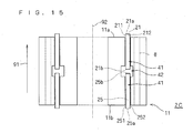
- the rotor 2a with the cavity 42 discussed in the third embodiment is not necessarily formed for example by the coupling between the rotors 1e and 1f. Such an alternative is shown as a rotor 2c in Fig. 15.
- the rotor 2c has a core 11, and magnets 21 and 25.
- the core 11 extends in a predetermined direction 91, and has a hole 41 and a cavity 42.
- the magnet 21 has pole faces 211 and 212, and the magnet 25 has poles faces 251 and 252.
- the hole 41 penetrates the core 11 through the cavity 42 in the predetermined direction 91 from one of the ends 11a and 11b of the core 11 to the other thereof.
- the cavity 42 has a cross-sectional area to the predetermined direction 91 that is greater than that of the hole 41 in the plane perpendicular to the predetermined direction 91.
- the magnets 21 and 25 are inserted into the hole 41. At this time, the pole faces 211 and 212 of the magnet 21 extend in the predetermined direction 91, and an end 21b of the magnet 21 protrudes into the cavity 42. The pole faces 251 and 252 of the magnet 25 extend in the predetermined direction 91, and an end 25b of the magnet 25 protrudes into the cavity 42.
- the magnets 21 and 25 are inserted into the hole 41 for example from the ends 11a and 11b of the core 11, respectively.
- magnets 21 and 25 protrude into the cavity 42 in the rotor 2c
- only one of the magnets 21 and 25 may protrude into the cavity 42, for example.
- magnetic flux is unlikely to be short-circuited at the end 21b of the magnet 21 when the magnet 21 protrudes into the cavity 42. This is also applicable to the case where the magnet 25 protrudes.
- the magnet 21 or 25 may protruded forward with respect to the end 11a or 11b of the core 11.
- magnetic resistance is increased at the end 21a of the magnet 21 when the magnet 21 protrudes forward.
- magnetic flux is unlikely to be short-circuited from either one of the pole faces 211 and 212 of the magnet 21 to the other thereof by passing through the end 21a of the magnet 21.
- This is also applicable to the case where the magnet-25 protrudes.
- Fig. 15 especially both the magnets 21 and 25 are shown to protrude forward in the predetermined direction 91.
- both ends of the rotor 2c in the predetermined direction 91 also desirably have recesses for exposing the ends 21a and 25a of the magnets 21 and 25.
- Fig. 16 conceptually shows a cross section of a rotor 2d according to a fifth embodiment.
- the rotor 2d has rotors 1g and 1h coupled to each other in the predetermined direction 91.
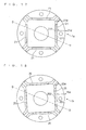
- the cross sections of the rotors 1d and 1h to the predetermined direction 91 are respectively shown in Figs. 17 and 18.
- the cross section shown in Fig. 16 is taken along dashed-dotted lines D-D indicated in Figs. 17 and 18.
- the rotor 1h has a core with parts 121 and 122, and a magnet 25, and has the same structure as that of the rotor 1g. Namely, the parts 121 and 122 respectively correspond to the parts 111 and 112, the magnet 25 corresponds to the magnet 21, and ends 25a and 25b of the magnet 25 in the predetermined direction 91 respectively correspond to the ends 21 and 21b.
- the rotor 1g is coupled to the rotor 1h in the predetermined direction 91. At this time, a normal direction 21d to the pole face 212 of the magnet 21 is tilted from a normal direction 25d to the pole face 252 of the magnet 25.
- Fig. 19 shows exemplary relative positions of the rotors 1g and 1h when viewed in the predetermined direction 91.
- the shapes of the rotors 1g and 1h shown in Fig. 19 are formed by protruding the rotors 1g and 1h in the predetermined direction 91 onto a plane that is perpendicular to the predetermined direction 91. Only one side of the rotor 2d with respect to a dashed-dotted line E-E passing through the rotation axis 92 is shown.
- the rotors 1g is indicated by solid lines and the rotor 1h is indicated by broken lines.
- the normal direction 25d of the rotor 1h is tilted in a counterclockwise direction about the rotation axis 92 from the normal direction 21d at a predetermined angle ⁇ .
- a hole 254 into which the magnet 25 is buried is therefore defined by rotating a hole 214 into which the magnet 21 is buried at the predetermined angle ⁇ counterclockwise about the rotation axis 92.
- these relative positions of the holes 214 and 215 are described by the expression that "step skew of holes is defined".
- the position of the magnet 25 is defined by rotating the position of the magnet 21 at the predetermined angle ⁇ counterclockwise about the rotation axis 92 when viewed in the predetermined direction 91.
- steps skew of magnets is defined.
- an outer edge 212e of the magnet 21 on the plane of projection (projected pole face 212) and an inner edge 251e of the magnet 25 on the plane of projection (projected pole face 251) do not intersect with each other. It is also desirable that an inner edge 211e of the magnet 21 on the plane of projection (projected pole face 211) and an outer edge 252e of the magnet 25 on the plane of projection (projected pole face 252) do not intersect with each other. This is because no magnetic material is held between the pole faces 211 or 212, and the pole faces 252 or 251 respectively, which prevents a short circuit of magnetic flux from one pole face to another pole face that are opposite in polarity and belong to the different magnets 21 and 25.
- the end 21a of the magnet 21 protrudes forward in the predetermined direction 91 and on the side opposite to the rotor 1h with respect to both the parts 111 and 112.
- the end 25a of the magnet 25 protrudes forward in a direction opposite to the predetermined direction 91 and on the side opposite to the rotor 1h with respect to both the ends 121 and 122.
- step skew of the magnets 21 and 25 is defined to thereby reduce torque ripple. Further, the respective ends of the magnets 21 and 25 parallel to the predetermined direction 91 protrude forward: This produces the same effect as that discussed in the first embodiment.
- Fig. 20 conceptually shows a cross section of a rotor 2e according to a sixth embodiment.
- the rotor 2e is formed by the rotors 1g and 1h coupled to each other through a magnetic plate 7.
- the cross sections of the rotor 1 g, the magnetic plate 7 and the rotor 1h to the predetermined direction 91 are respectively shown in Figs. 21, 22 and 23.
- the cross section shown in Fig. 20 is taken along dashed-dotted lines F-F indicated in Figs. 21 to 23.
- the same reference numerals are applied to the constituent parts of Fig. 20, 21 and 23 that correspond to those parts discussed in the fifth embodiment.
- the rotors 1g and 1h have holes 214 and 254 into which the magnets 21, and 25 are respectively buried (Figs. 21 and 23).
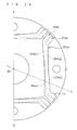
- Fig. 24 is an enlarged view of the cross section of Fig. 22, showing only one side of the magnetic plate 7 with respect to a dashed-dotted line G-G passing through the rotation axis 92.
- the magnetic plate 7 has a through hole 71.
- the through hole 71 penetrates the magnetic plate 7 in the predetermined direction 91 in an area 222s that includes projections 214s and 254s formed by projecting the holes 214 and 254 respectively onto the magnetic plate 7 to the predetermined direction 91, and extends from either the projection 214s or 254s to either the projection 254s or 214s.
- the through hole 71 provides a gap equal to or greater than the respective depths of the magnets 21 and 25 in the circumferential direction of the magnetic plate 7. Thus magnetic flux is unlikely to be short-circuited at the through hole 71 in the circumferential direction of the magnetic plate 7.
- the shape of the through hole 71 may be such that the cross section thereof to the predetermined direction 91 is the same for example with the cross sections of the holes 21 and 25 in the plane perpendicular to the predetermined direction 91.
- the through hole 71 may penetrate either through the hole 21 or through the hole 25 to thereby communicatively couple the holes 21 and 25.
- the through hole 71 may have a smooth side surface.
- the through hole 71 may have a stepwise structure extending from either the hole 21 or 25 to either the hole 25 or 21.
- an outer edge 214s2 of the projection 214s and an inner edge 254s1 of the projection 254s do not intersect with each other. It is further desirable that an inner edge 214s1 of the figure 214s and an outer edge 254s2 of the figure 254s do not intersect with each other. This is because no magnetic material is held between the pole faces 211 or 212, and the pole faces 252 or 251 respectively, which prevents a short circuit of magnetic flux from one pole face to another pole face that are opposite in polarity and belong to the different magnets 21 and 25.
- a thickness t1 of the magnetic plate 7 in the predetermined direction 91 is greater at least than either the thickness of the magnet 21 or that of the magnet 25.
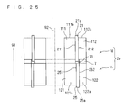
- At least either the magnet 21 or 25 may protrude into the through hole 71 as shown in Fig. 25.
- magnetic flux is unlikely to be short-circuited from either the pole face 211 or 212 (from either the pole face 251 or 252) to either the pole face 212 or 211 (to either the pole face 252 or 251) of the same protruding magnet 21 (25) by passing the ends of the magnet 21 (25), even when the magnets 21 and 25 are not in contact with each other.
- the rotor 2e discussed in the sixth embodiment is not necessarily formed by coupling the rotors 1g and 1h through the magnetic plate 7. This case is shown as a rotor 2f in Fig. 26.
- the rotor 2f has a core 11, and magnets 21 and 25.
- the core 11 extends in a predetermined direction 91, and has holes 43, 44 and a cavity 45.
- the magnet 21 has pole faces 211 and 212, and the magnet 25 has poles faces 251 and 252.
- the rotor 2f is seen as integration of the rotors 1g, 1h and the magnetic plate 7. More specifically, the holes 43 and 44 are respectively regarded as the holes 214 and 254 (Figs. 21 and 23), and the cavity 45 is regarded as the through hole 71 (Fig. 20).
- the cavity 45 is defined between ends 11a and 11b of the core 11 in the predetermined direction 91.
- the hole 43 extends from the end 11a in the predetermined direction 91 to protrude into the cavity 45.
- the hole 44 extends from the end 11b in the predetermined direction 91 to protrude into the cavity 45.
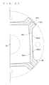
- Fig. 27 shows a cross section of the cavity 45 perpendicular to the predetermined direction 91.
- the cross section of the cavity 45 includes both projections 43s and 44s formed by projecting the holes 43 and 44 in the predetermined direction 91.
- the cross-sectional area of the cavity 45 to the predetermined direction 91 is greater than those of both the holes 43 and 44 to the predetermined direction 91.
- the magnets 21 and 25 are respectively inserted into the holes 43 and 44.
- the magnets 21 and 25 are inserted into the holes 43 and 44 from the ends 11a and 11b of the core 11 respectively.
- the pole faces 211 and 212 of the magnet 21, and the pole faces 251 and 252 of the magnet 25 extend in the predetermined direction 91.
- step skew of the holes 43 and 44 is defined to thereby define step skew of the magnets 21 and 25 respectively inserted into the holes 43 and 44. Further, as a result of the presence of the cavity 45, magnetic flux is unlikely to be short-circuited from either one of the pole faces 211, 212, 251 and 252 of the same magnet 21 and 25 to the other thereof by passing through the ends of the magnets 21 and 25, even when the two magnets 21 and 25 are not in contact with each other.
- an outer edge 43s2 of the projection 43s and an inner edge 44s1 of the projection 44s do not intersect with each other. It is further desirable that an inner edge 43s1 of the projection 43s and an outer edge 44s2 of the projection 44s do not intersect with each other. This is because no magnetic material is held between the pole faces 211 or 212, and the pole faces 252 or 251 respectively, which prevents a short circuit of magnetic flux from one pole face to another pole face that are opposite in polarity and belong to the different magnets 21 and 25.
- a thickness t2 of the cavity 45 in the predetermined direction 91 is set to be greater at least than either the thickness of the magnet 21 or the magnet 25.
- At least either the magnet 21 or 25 may protrude into the cavity 45.
- Fig. 28 shows a cross section of a motor 5 equipped especially with the rotor 1a. Like the cross section shown in Fig. 2, the cross section of Fig. 28 is taken along the cutting plane C-C indicated in Fig. 1.
- the rotor 1a is rotatably arranged about the rotation axis 92 extending in the predetermined direction 91.
- the stator 51 is coaxially with and faces the rotor 1a.
- the stator 51 has a coil (not shown) with which magnetic flux flowing from the rotor 1a links.
- an intended alternating current obtained for example by PWM control by an inverter is applied to this coil.
- Such an alternating current may be a sinusoidal current with intended amplitude and cycle. It is desirable that this coil is of a concentrated winding type. This is because a coil end length is reduced, which contributes to downsizing of the motor as a whole. This is also because magnetic flux can be efficiently linked with the coil of the stator 51 even in a reverse magnetic field without causing magnetic flux leakage at the end of the magnet 21.
- the above-discussed rotor 1a is employed as a rotor in the motor 5.
- the drive efficiency and drive output of the motor 5 are improved.
- This is also applicable to the case where any of the rotors 1b through 1d, and 2a through 2c is employed as a rotor in the motor 5.
- a height d of the magnet 21 from the end 111b of the part 111 of the core 11 taken along the rotation axis 92 is desirably smaller than a distance M between the pole faces 211 and 212 of the same magnet 21 for the reason given next. That is, magnetic flux is unlikely to be short-circuited from the pole face 211 to the pole face 212 by passing through the end 21b of the magnet 21. This is because, when magnetic flux generated at the protruding portion of the magnet 21 flows into the part 111, the magnetic flux passes through a non-magnetic part such as air a shorter distance as compared to the case where the magnetic flux flows into the end 21b of the magnet 21. As a result, magnetic resistance is reduced. This is also applicable to the side of the end 21a of the magnet 21.
- the distance M is greater than a distance A between the rotors 1a through 1d and 2a through 2c, and the surface of the stator 51 facing these rotors for the reason given next. That is, a short circuit is unlikely to occur from the pole face 212 to the pole face 211 by passing through the ends 21a and 21b of the magnet 21. Namely, magnetic flux flows into the stator 51 in large quantities. This is because the flow of magnetic flux into the stator 51 results in smaller magnetic resistance.
- the motor discussed in the present embodiment can be mounted for example on a compressor, in which case effective compression for example of a refrigerant is realized.
- the core 11 may be a stack of magnetic steel sheets. Further, application for example of dust core is desirable in terms of reduction of eddy current.
- the core 11 may have means for determining the position of the magnet 21 with respect to the core 11, or means for fixing the magnet 21 at the position thereby determined.
- the core 11 may be held for example by end plates from both sides of the core 11 in the predetermined direction 91 to thereby fix the magnet 21.
- the core 11 may be held for example by end plates from both sides of the core 11 in the predetermined direction 91 to thereby fix the magnet 21.
- the magnet 21 protrudes forward with respect to the ends 11a and 11b of the core 11 as in the rotor 1d shown in Fig. 8
- an example shown for example in Fig. 29 is applicable to fix the magnet 21.
- the rotor 1d is held from both sides in the predetermined direction 91 by end plates 7a and 7b.
- the end plates 7a and 7b are depressed on the side of the part 111 in the predetermined direction 91 by heights La and Lb that respectively correspond to the protruding parts of the ends 11a and 11b of the magnet 21.
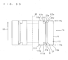
- the core 11 may have a protrusion 6 for realizing positioning and fixation of the magnet 21 as shown in Fig. 30.
- the protrusion 6 is arranged such that the positions of the ends 21a and 21b of the magnet 21 are determined, for example. It is desirable that the degree of the protrusion 6 is controlled such that magnetic flux is not short-circuited through the protrusion 6.
- a magnet is desirably a rare-earth permanent magnet that provides a large energy product. It is especially desirable to employ a sintered magnet of Md-Fe-B system in terms of increase of the amount of magnetic flux.
Landscapes
- Engineering & Computer Science (AREA)
- Power Engineering (AREA)
- Permanent Field Magnets Of Synchronous Machinery (AREA)
Abstract
Description
- The present invention relates to a core, a rotor, a motor and a compressor, and, more specifically, to relative positions of a magnet and a core holding the magnet buried therein.
- Permanent magnet motors are classified for example into a rotating armature type with a permanent magnet arranged on the side of a stator, and a rotating field type with a permanent magnet arranged on the side of a rotor. In a motor of the rotating field type, linkage of magnetic flux generated by a permanent magnet (hereinafter referred to as a "magnet") of a rotor with a coil on the side of a stator is generated to thereby rotate the rotor.
- A particular structure of a rotor of the rotating field motor is such that a magnet is buried in a core that extends in a direction of a rotation axis, and a pole face of the magnet extends in the direction of the rotation axis.
- Techniques relevant to the present invention are introduced in the following publications.
-
- Patent Publication 1:
Japanese Patent Application Laid-Open No. 11-234931 (1999 - Patent Publication 2:
Japanese Patent Application Laid-Open No. 2000-209799 - Patent Publication 3:
Japanese Patent Application Laid-Open No. 2001-37119 - In a rotor disclosed in
patent publications 1 to 3 listed above, an end of a magnet defined in a direction of a rotation axis is depressed or flat with respect to an end of a core defined in the same direction. This causes magnetic flux generated by the magnet to be short-circuited from one pole face to another pole face of the same magnet by passing through the end of the magnet. - Figs. 31 and 32 show a short circuit of magnetic flux generated in a conventional rotor by magnetic lines of force. In Fig. 30, an end of a magnet is depressed with respect to an end of a core. In Fig. 31, an end of a magnet is flat with respect to an end of a core.
- When a short circuit of magnetic flux is generated in a rotor, magnetic flux passing from the rotor to a stator is reduced to cause reduction of drive efficiency or drive output of a motor.
- The present invention has been made in view of the above-discussed circumstances. The present invention is intended to prevent a short circuit of magnetic flux in a rotor.
- According to a first aspect of a rotor of the present invention, the rotor comprises: a core (11) extending in a predetermined direction (91); and a magnet (21) buried in the core and having pole faces (211, 212) extending in the predetermined direction. The core has a first part (111; 112) formed by a magnetic material and facing one of the pole faces (211; 212). At least one of ends (21a; 21a) of the magnet defined in the predetermined direction protrudes forward in the predetermined direction with respect to an end (111a; 112a) of the first part, the end of the first part being on the same side with the at least one of the ends of the magnet.
- According to a second aspect of a rotor of the present invention, in the first aspect of the rotor, both of the ends (21a; 21b) of the magnet protrude forward with respect to the ends (112a, 112b) of the first part (112), the ends of the first part being on the same sides with corresponding ones of the ends of the magnet. A length (Lm) of the magnet in the predetermined direction (91) satisfies a ratio (Lm / Lo) not more than 1.075 to a length (Lo) of the first part in the predetermined direction.
- According to a third aspect of a rotor of the present invention, in the first or second aspect of the rotor, the ends (111a, 111b; 112a, 112b) of the first part (111; 112) have recesses (111c, 11d; 112c, 112d) for exposing the ends (21a, 21b) of the magnet (21).
- According to a fourth aspect of a rotor of the present invention, in any one of the first through third aspects of the rotor, the core (11) further has a second part (112; 111) formed by a magnetic material and facing another one of the pole faces (212; 211). At least one of the ends (21a; 21a) of the magnet protrudes forward in the predetermined direction (91) with respect to an end (112a; 111a) of the second part, the end of the second part being on the same side with the at least one of the ends of the magnet.
- According to a fifth aspect of a rotor of the present invention, in the fourth aspect of the rotor, the ends (112a, 112b; 111a, 111b) of the second part (112; 111) have recesses (
111c 111d; 112c, 112d) for exposing the ends (21a, 21b) of the magnet (21). - According to a sixth aspect of a rotor of the present invention, in any one of the first through fifth aspects of the rotor, the magnet (21) includes a plurality of magnets arranged in a loop. The core (11) further has a third part (113) formed by a magnetic material and arranged between adjacent ones of the magnets (21). At least one of ends (113a; 113b) of the third part defined in the predetermined direction (91) protrudes forward in the predetermined direction with respect to the ends (21a; 21b) of the adjacent ones of the magnets (21), the ends of the adjacent ones of the magnets being on the same side with at least one of ends of the third part.
- According to a seventh aspect of a rotor of the present invention, in any one of the first through fifth aspects of the rotor, the magnet (21) includes a plurality of magnets arranged in a loop. The core (11) further has a third part (113) formed by a magnetic material and arranged between adjacent ones of the magnets (21). At least one of ends (113a; 113b) of the third part defined in the predetermined direction (91) is depressed in the predetermined direction with respect to the ends (21a; 21b) of the adjacent ones of the magnets (21), the ends of the adjacent ones of the magnets being on the same side with at least one of the ends of the third part.
- According to an eighth aspect of a rotor of the present invention, the rotor comprises any two or more of the rotors (1e, 1f; 1d, 1d; 1g, 1h) as recited in the first through seventh aspects coupled together in the predetermined direction (91). The magnet (21, 25; 21, 21; 21, 25) protrudes forward with respect to the part (111, 112, 121, 122; 111, 112, 111, 112; 111, 112, 121, 122) of the core on the side of at least one of ends of the rotors defined in the predetermined direction, the at least one of the ends having no coupling to another end.
- According to a ninth aspect of a rotor of the present invention, the rotor comprises any two or more of the rotors (1e, 1f) as recited in the first through seventh aspects coupled together in the predetermined direction (91). The part (111, 112, 121, 122) of the core has a recess (111d, 112d, 121d, 122d) for exposing the end (21a, 25a) of the magnet (21, 25) on the side of at least one of ends of the rotors coupling to each other, the at least one of the ends being defined in the predetermined direction.
- According to a tenth aspect of a rotor of the present invention, in the eighth or ninth aspect of the rotor, the two or more of the rotors (1d, 1d) are coupled through a non-magnetic material (3).
- According to an eleventh aspect of a rotor of the present invention, the rotor comprises: a core (11) having a hole (41) and a cavity (42), the core extending in a predetermined direction (91); and at least two magnets (21, 25) having pole faces (211, 212; 251, 252). The hole penetrates the core through the cavity in the predetermined direction from one end (11a) to another end (11b) of the core. The cavity has a cross-sectional area to the predetermined direction that is greater than that of the hole to the predetermined direction. A first one of the magnets (21; 25) is inserted into the hole, the pole faces (211, 212; 251, 252) of the first one of the magnets extending in the predetermined direction. A second one of the magnets (25; 21) is inserted into the hole on the side opposite to the first one of the magnets with respect to the cavity, the pole faces (251, 252; 211, 212) of the second one of the magnets extending in the predetermined direction. An end (21b, 25b) of at least one of the magnets respect to the predetermined direction protrudes into the cavity.
- According to a twelfth aspect of a rotor of the present invention, in the eleventh aspect of the rotor, at least one of the magnets (21; 25) has an end (21a, 25a) in the predetermined direction (91) that protrudes forward with respect to the end (11a, 11b) of the core (11).
- According to a thirteenth aspect of a rotor of the present invention, in the eighth aspect of the rotor, the two or more of the rotors (1g, 1h) include a first rotor (1g) and a second rotor (1h). A normal direction (21d) to the pole face (212) of the magnet (21) of the first rotor is tilted from a normal direction (25d) to the pole face (251) of the magnet (25) of the second rotor.
- According to a fourteenth aspect of a rotor of the present invention, in the thirteenth aspect of the rotor, in a first projection formed by protruding the magnet (21) of the first rotor (1g) onto a predetermined plane perpendicular to the predetermined direction (91) and in a second projection formed by protruding the magnet (25) of the second rotor (1h) onto the predetermined plane perpendicular to the predetermined direction, an outer edge (212e) of the first projection and an inner edge (251e) of the second projection do not intersect with each other, while an inner edge (211e) of the first projection and an outer edge (252e) of the second projection do not intersect with each other.
- According to a fifteenth aspect of a rotor of the present invention, in the thirteenth or fourteenth aspect of the rotor, the first rotor (1g) and the second rotor (1h) both have holes (214, 254) into which the magnets (21, 25) are buried. The first rotor and the second rotor are coupled to each other through a magnetic plate (7). The magnetic plate has a through hole (71). The through hole penetrates the magnetic plate in the predetermined direction in an area (222s), the area including projections (214s, 254s) formed by protruding the hole of the first rotor and the hole of the second rotor onto the magnetic to the predetermined direction (91), the area extending from one to the other of the projections.
- According to a sixteenth aspect of a rotor of the present invention, in the fifteenth aspect of the rotor, a thickness (t) of the magnetic plate is greater at least than either the thickness of the magnet of the first rotor or the thickness of the magnet of the second rotor.
- According to a seventeenth aspect of a rotor of the present invention, in the fifteenth or sixteenth aspect of the rotor, at least either the magnet (21) of the first rotor (1g) or the magnet (25) of the second rotor (1h) protrudes into the through hole (71).
- According to an eighteenth aspect of a rotor of the present invention, the rotor has a cavity (45), and first and second holes (43, 44). The rotor comprises: a core (11) extending in a predetermined direction (91); and first and second magnets (21; 25) having pole faces (211, 212; 251, 252). The first hole extends in the predetermined direction from an end (11a) of the core defined in the predetermined direction to communicate with the cavity. The second hole extends in the predetermined direction from another end of the core defined in the predetermined direction to communicate with the cavity. The cross section of the cavity taken to the predetermined direction includes both first and second projections (214s, 254s) formed by protruding the first and second holes defined in the predetermined direction. The cross section has an area greater than those of both the first and second holes defined in the predetermined direction. The first magnet is inserted into the first hole, the pole faces of the first magnet extending in the predetermined direction. The second magnet is inserted into the second hole, the pole faces of the second magnet extending in the predetermined direction.
- According to a nineteenth aspect of a rotor of the present invention, in the eighteenth aspect of the rotor, an outer edge (214s2) of the first projection (214s) and an inner edge (254s1) of the second projection (254s) do not intersect with each other, while an inner edge (214s1) of the first projection and an outer edge (254s2) of the second projection do not intersect with each other.
- According to a twentieth aspect of a rotor of the present invention, in any one of the first through nineteenth aspects of the rotor, the core (11) has a first gap (41; 41) and a second gap (43; 411) both extending in the predetermined direction (91). The first gap extends in a first direction (95; 95) perpendicular to the predetermined direction, the first gap holding the magnet (21; 21) buried therein. The second gap is defined at an end (41a; 41b) of the first gap in the first direction, the second gap extending in a second direction (93; 95) perpendicular to the predetermined direction. A width of the second gap (Wa1; Wa2) defined in a direction (94; 96) perpendicular to both of the predetermined direction and the second direction is greater than a distance (M; M) between the pole faces (211, 212; 211, 212) of the magnet.
- According to a first aspect of a motor of the present invention, the motor comprises: the rotor (1a to 1d, 2a to 2c) as recited in any one of the first through twentieth aspects, the rotor rotating about a rotation axis (92) extending in the predetermined direction (91); and a stator (51) arranged coaxially with the rotor and facing the rotor.
- According to a second aspect of a motor of the present invention, in the first aspect of the motor, a height (d) of the magnet (21) from the end (111b) of the core (111) taken along the rotation axis (92) is smaller than a distance (M) between the pole faces (212, 212) of the same magnet (21), the end of the core being on the side opposite to the stator (51) with respect to the magnet.
- According to a third aspect of a motor of the present invention, in the first or second aspect of the motor, a distance (M) between the pole faces (211, 212) of the same magnet (21) is greater than a distance (A) between a side surface of the rotor (1a) and a surface of the stator (51) facing the side surface.
- A compressor according to the present invention comprises the motor (5) as recited in any one of the first through third aspects.
- According to a first aspect of a core of the present invention, the core has first and second parts (111, 112) formed by magnetic materials, the first and second parts both extending in a predetermined direction (91). The first and second parts face each other through a gap (41) extending in the predetermined direction. At least one of ends (111a; 112a) of the first part (111; 112) defined in the predetermined direction protrudes forward in the predetermined direction with respect to an end (112a; 111a) of the second part, the end of the second part being on the same side with the at least one of the ends of the first part.
- According to a second aspect of a core of the present invention, in the first aspect of the core, an end of the gap (41) defined in the predetermined direction (91) extends toward the second part (112; 111).
- According to a third aspect of a core of the present invention, the core has first and second parts (111, 112) formed by magnetic materials, the first and second parts both extending in a predetermined direction (91). The first and second parts face each other through a gap (41) extending in the predetermined direction. An end of the gap (41) defined in the predetermined direction (91) extends toward the first and second parts.
- According to a fourth aspect of a core of the present invention, in any one of the first through third aspects of the core, the core further comprises: two or more of the first parts (112); and a plurality of third parts (113) formed by magnetic materials, the third parts extending in the predetermined direction. The first parts (112) and the plurality of third parts are alternately arranged in a loop around the second part (111). At least one of ends (113a;113b) of the third part in the predetermined direction protrudes forward in the predetermined direction with respect to the end (112a;112b) of the second part, the end of the second part being on the same side with the at least one of the ends of the third part.
- According to a fifth aspect of a core of the present invention, in any one of the first through third aspects of the core, the core further comprises: two or more of the first parts (112); and a plurality of third parts (113) formed by magnetic materials, the third parts extending in the predetermined direction. The first parts (112) and the plurality of third parts are alternately arranged in a loop around the second part (111). At least one of ends (113a;113b) of the third part in the predetermined direction is depressed in the predetermined direction with respect to the end (111a; 111b) of the first part, the end of first second part being on the same side with the at least one of the ends of the third part.
- According to a sixth aspect of a core of the present invention, the core extends in a predetermined direction (91), and comprises a hole (41) and a cavity (42). The hole penetrates the core through the cavity in the predetermined direction from one end (11a) to another end (11b) of the core. The cavity has a cross-sectional area to the predetermined direction that is greater than that of the hole in the plane perpendicular to the predetermined direction.
- According to a seventh aspect of a core of the present invention, the core extends in a predetermined direction (91). The core comprises a cavity (45); a first hole (43) extending in the predetermined direction from one end (11a) of the core to protrude into the cavity; and a second hole (44) extending in the predetermined direction from another end (11b) of the core to protrude into the cavity. The cross section of the cavity to the predetermined direction includes both first and second projections (43s, 44s) formed by protruding the first and second holes defined in the predetermined direction. The cross section having an area greater than those of both the first and second holes defined in the predetermined direction.
- According to an eighth aspect of a core of the present invention, in the seventh aspect of the core, an outer edge (43s2) of the first projection (43s) and an inner edge (44s1) of the second projection (44s) do not intersect with each other, while an inner edge (43s1) of the first projection and an outer edge (44s2) of the second projection do not intersect with each other.
- According to the first aspect of the rotor of the present invention, magnetic resistance at the protruding end of the magnet is increased. Thus magnetic flux is unlikely to be short-circuited from one pole face to another pole face of the same magnet by passing through the end of this magnet.
- According to the second aspect of the rotor of the present invention, when a stator is arranged to face the pole face of the magnet when viewed from the first part, the amount of magnetic flux flowing into the stator increases.
- According to the third aspect of the rotor of the present invention, a part of the end of the first part is aligned in the predetermined direction with the end of the magnet. Thus the magnet can be easily fixed to the core, by which the rotor can be made easily.
- According to the fourth aspect of the rotor of the present invention, especially when the magnet protrudes forward with respect to both the first and second parts on the side of at least one end of the core, magnetic resistance at the protruding end of the magnet is increased. Thus magnetic flux is unlikely to be short-circuited from one pole face to another pole face of the same magnet by passing through the end of this magnet.
- According to the fifth aspect of the rotor of the present invention, a part of the end of the second part is aligned in the predetermined direction with the end of the magnet. Thus the magnet can be easily fixed to the core, by which the rotor can be made easily.
- According to the sixth aspect of the rotor of the present invention, magnetic saturation in the third part is prevented to thereby prevent the reduction of reluctance torque.
- According to the seventh aspect of the rotor of the present invention, magnetic flux is unlikely to be short-circuited at the depression from one pole face to another pole face of the same magnet.
- According to the eighth aspect of the rotor of the present invention, magnetic resistance at the protruding end of the magnet is increased. Thus magnetic flux is unlikely to be short-circuited from one pole face to another pole face of the same magnet by passing through the end of this magnet. Further, the rotor is made by independently forming a plurality of rotors. Thus the rotor with large dimensions in the predetermined direction can be made easily. Further, step skew can be defined between a magnet of one rotor and a magnet of another rotor.
- According to the ninth aspect of the rotor of the present invention, the rotor is made by independently forming a plurality of rotors. Thus the rotor with large dimensions in the predetermined direction can be made easily. Further, step skew can be defined between a magnet of one rotor and a magnet of another rotor. Still further, the core has the recess for exposing the end of the magnet on the side where the rotors are coupled. Thus, magnetic flux is unlikely to be short-circuited from one pole face to another pole face of the same magnet by passing between one magnet and another magnet, even when these magnets are not in contact with each other at the time of coupling between the rotors. This results from large magnetic resistance at the recess.
- According to the tenth aspect of the rotor of the present invention, a non-magnetic material is present at the end of the magnet. Thus, magnetic flux is unlikely to be short-circuited from one pole face to another pole face of the same protruding magnet by passing between the magnets, even when the magnets of the rotors are not in contact with each other at the time of coupling between the rotors.
- According to the eleventh aspect of the rotor of the present invention, even when the magnets inserted into the holes are not in contact with each other, an end of at least one of the magnets protrudes into the cavity. Thus magnetic flux is unlikely to be short-circuited from one pole face to another pole face of this magnet by passing between the magnets.
- According to the twelfth aspect of the present invention, at least one of the magnets has an end that protrudes forward with respect to the end of the core. Thus magnetic resistance at the protruding end is increased, by which magnetic flux is unlikely to be short-circuited from one pole face to another pole face of the same magnet by passing through the end of this magnet.
- According to the thirteenth aspect of the present invention, step skew of the magnets of the first and second rotors is defined to thereby reduce torque ripple.
- According to the fourteenth aspect of the present invention, no magnetic material is held between the pole face of the magnet of the first rotor and the pole face of the magnet of the second rotor. This prevents a short circuit of magnetic flux from one pole face to another pole face that are opposite in polarity and belong to the different magnets.
- According to the fifteenth aspect of the rotor of the present invention, step skew is defined between the magnet of the first rotor and the magnet of the second rotor. Thus the through hole provides a gap equal to or greater than the respective depths of these magnets in the circumferential direction of the magnetic plate. Thus magnetic flux is unlikely to be short-circuited at the through hole in the circumferential direction of the magnetic plate.
- According to the sixteenth aspect of the rotor of the present invention, even when a magnetic material is held between the pole face of the magnet of the first rotor close to the magnet of the second rotor and the pole face of the magnet of the second rotor close to the magnet of the first rotor, the magnetic material at this position is spaced apart by the presence of the through hole in the predetermined direction by the thickness of the magnetic plate. Further, the thickness of the magnetic plate is greater than either the thickness of the magnet of the first rotor or that of the magnet of the second rotor. As a result, a short circuit of magnetic flux does not occur between these pole faces by using the through hole as a flux path.
- According to the seventeenth aspect of the rotor of the present invention, even when the magnet of the first rotor and the magnet of the second rotor are not in contact with each other, magnetic flux is unlikely to be short-circuited from one pole face to another pole face of the same protruding magnet by passing through the end of this magnet.
- According to the eighteenth aspect of the rotor of the present invention, step skew can be defined between the first and second magnets. Further, as a result of the presence of the cavity, magnetic flux is unlikely to be short-circuited from one pole face to another pole face of the same magnet by passing through the end of this magnet, even when the first and second magnets are not in contact with each other.
- According to the nineteenth aspect of the rotor of the present invention, no magnetic material is held between the pole face of the first magnet and that of the second magnet. This prevents a short circuit of magnetic flux from one pole face to another pole face that are opposite in polarity and belong to the different magnets.
- According to the twentieth aspect of the rotor of the present invention, magnetic flux is unlikely to be short-circuited from one pole face to another pole face of the same magnet by passing through the second gap at the end of the magnet close to the second gap.
- According to the first aspect of the motor of the present invention, the drive efficiency and drive output of the motor are improved.
- According to the second aspect of the motor of the present invention, magnetic flux is unlikely to be short-circuited from the pole face on the side opposite to the stator to the pole face on the side of the stator by passing through the end of the magnet.
- According to the third aspect of the motor of the present invention, magnetic flux is unlikely to be short-circuited from the pole face on the side of the stator to the pole face on the side opposite to the stator by passing through the end of the magnet. Namely, magnetic flux flows into the stator in large quantities
- The compressor of the present invention realizes effective compression for example of a refrigerant.
- According to the first aspect of the core of the present invention, in a rotor formed by inserting a magnet into the gap, an end of the magnet defined in the predetermined direction is located between the ends of the first and second parts in the predetermined direction. Thus magnetic flux is unlikely to be short-circuited from one pole face to another pole face of the same magnet by passing through the end of this magnet.
- According to the second aspect of the core of the present invention, in a rotor formed by inserting a magnet into the gap, a recess for exposing an end of this magnet is formed at the end of the second part. Thus a part of the end of the second part is aligned in the predetermined direction with the end of the magnet. As a result, the magnet can be easily fixed to the core.
- According to the third aspect of the core of the present invention, in a rotor formed by inserting a magnet into the gap, recesses for exposing an end of this magnet are formed at the ends of the first and second parts. Thus respective parts of the ends of the first and second parts is aligned in the predetermined direction with the end of the magnet. As a result, the magnet can be easily fixed to the core.
- According to the fourth aspect of the core of the present invention, in a rotor formed by inserting a magnet into the gap, the reduction of reluctance torque is prevented when the end of the third part in the predetermined direction protrudes forward in the predetermined direction with respect to an end of the magnet.
- According to the fifth aspect of the core of the present invention, in a rotor formed by inserting a magnet into the gap, when the end of the third part in the prescribed direction is depressed with respect to an end of the magnet, magnetic flux is unlikely to be short-circuited at the depression from one pole face to another pole face of the same magnet.
- According to the sixth aspect of the core of the present invention, in a rotor formed by inserting magnets into the hole from both ends of the core, at least one of the magnets protrudes into the cavity. Thus, even when these magnets are not in contact with each other, magnetic flux is unlikely to be short-circuited from one pole face to another pole face of this at least one magnet by passing between the two magnets.
- According to the seventh aspect of the core of the present invention, when magnets are inserted into the first and second holes, step skew can be defined between these magnets. Further, as a result of the presence of the cavity, magnetic flux is unlikely to be short-circuited from one pole face to another pole face of the same magnet by passing through the end of this magnet, even when the magnets are not in contact with each other.
- According to the eighth aspect of the core of the present invention, when first and second magnets are respectively inserted into the first and second holes, no magnetic material is held between the pole face of the first magnet and the pole face of the second magnet. This prevents a short circuit of magnetic flux from one pole face to another pole face that are opposite in polarity and belong to the different magnets.
- These and other objects, features, aspects and advantages of the present invention will become more apparent from the following detailed description of the present invention when taken in conjunction with the accompanying drawings.
-
- [Fig. 1 is a perspective view conceptually showing a
rotor 1a discussed in a first embodiment; - [Fig. 2] is a top view of the
rotor 1a viewed in apredetermined direction 91; - [Fig. 3] shows a cross section of the
rotor 1a taken along a cutting plane C-C; - [Fig. 4] shows magnetic flux flowing in the
rotor 1a by magnetic lines of force; - [Fig. 5] conceptually shows a cross section of a
rotor 1b discussed in the first embodiment; - [Fig. 6] shows variations in a magnetic flux quantum φ a/Lm relative to a ratio Lm/Lo;
- [Fig. 7] conceptually shows a cross section of a rotor 1c discussed in the first embodiment;
- [Fig. 8] conceptually shows a cross section of a
rotor 1d discussed in a second embodiment; - [Fig. 9] shows magnetic flux flowing in the
rotor 1d by magnetic lines of force; - [Fig. 10] conceptually shows a cross section of a rotor in which an end of a core has a recess;
- [Fig. 11] conceptually shows a cross section of a rotor in which an end of a core has a recess;
- [Fig. 12] conceptually shows a cross section of a rotor provided with several magnets;
- [Fig. 13] conceptually shows a cross section of a
rotor 2a discussed in a third embodiment; - [Fig. 14] conceptually shows a cross section of a
rotor 2b discussed in the third embodiment; - [Fig. 15] conceptually shows a cross section of a rotor 2c discussed in a fourth embodiment;
- [Figs. 16] conceptually shows a cross section of a
rotor 2d discussed in a fourth embodiment; - [Fig. 17] conceptually shows a cross section of the
rotor 1g to thepredetermined direction 91; - [Fig. 18] conceptually shows a cross section of the
rotor 1g to thepredetermined direction 91; - [Fig. 19] shows exemplary relative positions of
rotors predetermined direction 91; - [Fig. 20] conceptually shows a cross section of a
rotor 2e discussed in a sixth embodiment; - [Fig. 21] conceptually shows a cross section of the
rotor 1g to thepredetermined direction 91; - [Fig. 22] conceptually shows a cross section of a
magnetic plate 7 to thepredetermined direction 91; - [Fig. 23] conceptually shows a cross section of a
rotor 1h to thepredetermined direction 91; - [Fig. 24] is an enlarged view of the cross section of the
magnetic plate 7; - [Fig. 25] conceptually shows a cross section of an aspect in which a magnet protrudes into a through hole;
- [Fig. 26] conceptually shows a cross section of a
rotor 2f discussed in a seventh embodiment; - [Fig. 27] conceptually shows a cross section of a
cavity 45 to thepredetermined direction 91; - [Fig. 28] conceptually shows a cross section of a
motor 5 discussed in an eighth embodiment; - [Fig. 29] conceptually shows a cross section of an aspect in which a magnet is fixed by end plates;
- [Fig. 30] conceptually shows a cross section of a rotor provided with a protrusion;
- [Fig. 31] shows magnetic flux flowing in a conventional rotor by magnetic lines of force; and
- [Fig. 32] shows magnetic flux flowing in a conventional rotor by magnetic lines of force.
- Fig. 1 is a perspective view conceptually showing a
rotor 1a according to a first embodiment. Fig. 2 is a top view of therotor 1a viewed in apredetermined direction 91. Fig. 3 shows a cross section of therotor 1a at a position C-C. - The
rotor 1a comprises a core 11 extending in thepredetermined direction 91, and a plurality ofmagnets 21. - The core has
parts 111 to 113 formed by magnetic materials and extending in thepredetermined direction 91, wherein theparts holes 8 shown in Fig. 1. Then at least one side of each bolt is fastened by a nut or a rivet pin. In Fig. 3, theholes 8 are indicated by dashed lines. - The
parts part 111. Theparts 112 face thepart 111 throughgaps 41. - The
magnets 21 are buried in thegaps 41, and arranged in the form of a loop in thecore 11. Themagnets 21 each have pole faces 211 and 212 extending in thepredetermined direction 91. Themagnets 21 each have exposed ends 21a and 21b defined in thepredetermined direction 91. - The
parts 111 to 113 are described as follows in terms of the relations with themagnets 21. That is, thepart 111 is arranged to face the pole faces 211; and theparts 112 are arranged to face the pole faces 212. Theparts 113 are arranged between adj acent ones of themagnets 21. - The
rotor 1a is applied for example to a motor with a stator, and rotates about arotation axis 92 extending in thepredetermined direction 91. A stator (not shown) is arranged coaxially with therotor 1a and faces therotor 1a. More specifically, the stator is arranged to face the outer peripheral surface of therotor 1a. - In this case, the
part 111 is arranged to face the pole faces 211 on the side opposite to the stator with respect to themagnets 21. Theparts magnets 21. - In each of the
magnets 21, at least either theend magnet 21 protrudes forward in thepredetermined direction 91 with respect to anend 111a or anend 111b of thepart 111 that are respectively on the same sides with theends ends predetermined direction 91 with respect to thepart 111. - According to this aspect, magnetic resistance at the protruding ends 21a and 21b of the
magnet 21 is increased. Thus magnetic flux is unlikely to be short-circuited from either one of the pole faces 211 and 212 of thesame magnet 21 to the other thereof by passing through theends magnet 21. - Fig. 4 shows magnetic flux flowing in the
rotor 1a discussed above by magnetic lines of force. The magnetic flux generated in themagnet 21 flows from thepart 111, passing through themagnet 21 and thepart 112, and then flows into astator 51 without causing a short circuit even in theend 21a of themagnet 21. - In each of the
magnets 21, at least either theend magnet 21 may protrude forward in thepredetermined direction 91 with respect to anend 112a or anend 112b of thepart 112 that are respectively on the same sides with theends rotor 1b shown in Fig. 5, both theends magnet 21 are particularly shown to protrude forward in thepredetermined direction 91 with respect to thepart 112. This aspect produces the same effect as that discussed above. - Fig. 6 shows variations in a magnetic flux quantum relative to a ratio Lm/Lo where Lm is a length of the
magnet 21 in thepredetermined direction 91 and Lo is the length of thepart 112 in thepredetermined direction 91. For a magnetic flux quantum, a quantum φ a/Lm is applied that indicates a quantum of magnetic flux φ a flowing into a stator per unit length of themagnet 21. - The ratios Lm/Lo lower than 1, equal to 1 and higher than 1 respectively indicate the cases where both the
ends magnet 21 are depressed, flat and protrude forward with respect to theends part 112 that are respectively on the same sides with theends - The quantum φ a/Lm increases with the increase of the ratio Lm/Lo from 0.95. The reason therefor is considered that a short circuit of magnetic flux is prevented in the
ends magnet 21. The quantum φ a/Lm decreases with the increase of the ratio Lm/Lo from around 1.05. The reason therefor is considered that a considerable degree of protrusion of themagnet 21 results in a short circuit of magnetic flux. - Considering the quantum φ a/Lm that is obtained when the ratio Lm/Lo is 1 as a reference value, the quantum φ a/Lm is the same as or higher than this reference value when the ratio Lm/Lo is not smaller than 1 and not higher than 1.075. That is, the amount of magnetic flux flowing into a stator increases.
- The above discussions with reference to Fig. 6 are given in a situation where the
magnet 21 has a thickness of 1.5 mm to 4 mm. These discussions are also applicable when the thickness of themagnet 21 goes, out of this range. - As an example, a rotor 1c shown in Fig. 7 produces the same effect as that discussed above. Namely, in the stator 1c, the
end 21a of themagnet 21 protrudes forward in thepredetermined direction 91 with respect to theend 111a of thepart 111 that is on the same side with theend 21a. Theend 21b of themagnet 21 protrudes forward in thepredetermined direction 91 with respect to theend 112b of thepart 112 that is on the same side with theend 21b. - Fig.8 conceptually shows a cross section of a
rotor 1d according to a second embodiment. In therotor 1d, at least either theend magnet 21 protrudes forward in thepredetermined direction 91 with respect to both theend part 111 and theend part 112 that are on the same side with theend ends parts - According to this aspect, magnetic resistance at the
protruding end magnet 21 is increased to a greater degree. Thus magnetic flux is unlikely to be short-circuited from either one of the pole faces 211 and 212 of thesame magnet 21 to the other thereof by passing through theends magnet 21. - Fig. 9 shows magnetic flux flowing in the
rotor 1d by magnetic lines of force. The magnetic flux generated in themagnet 21 flows from thepart 111, passing through themagnet 21 and thepart 112, and then flows into thestator 51 without causing a short circuit even in theend 21a of themagnet 21. - In each of the embodiments described above, at least one of the
ends 113a and 113b of thepart 113 in thepredetermined direction 91 desirably protrudes forward in thepredetermined direction 91 with respect to theends magnets 21 adjacent to each other with thispart 113 held therebetween, where these ends 21a and 21b are respectively on the same sides with theends 113a and 113b. This aspect is shown for example in Fig. 1. Although not shown in Fig. 1, the end 113b is on the side opposite to the 113a of the part 113: - According to this aspect, magnetic saturation in the
part 113 is prevented to thereby prevent the reduction of reluctance torque. - At least either the
end 113a or 113b of thepart 113 is also desirably depressed in thepredetermined direction 91 with respect to theends magnets 21 adjacent to each other with thispart 113 held therebetween, where these ends 21a and 21b are respectively on the same sides with theends 113a and 113b. The reason therefor is that magnetic flux is unlikely to be short-circuited from one of the pole faces 211 and 212 of thesame magnet 21 to the other thereof. - This example is desirable especially in a situation where the
part 113 has agap 43 communicating to thegap 41, and the width of thisgap 43 is smaller than a distance between the pole faces 211 and 212 of thesame magnet 21 as shown in Fig. 2. This is because, although a short circuit is likely to occur in this case from either one of the pole faces 211 and 212 of thesame magnet 21 to the other thereof through this gap, a short circuit of magnetic flux is less likely at the depression of thepart 113 formed by defining thepart 113 at a lower level than themagnet 21. - In both of the aspects described above in which the
end 113a or 113b of thepart 113 protrudes forward or is depressed with respect to theend magnet 21, a distance Wa1 between theparts gap 43 is desirably greater than a distance M between the pole faces 121 and 122 of the magnet 21 (Fig. 2). - This is because magnetic flux is unlikely to be short-circuited at an
end 41b of themagnet 21 close to thepart 113 from one of the pole faces 211 and 212 of thesame magnet 21 to the other thereof by passing through thegap 43. - Considering the
gaps first gap 41 extends in adirection 95 perpendicular to thepredetermined direction 91, and holds themagnet 21 buried therein. Thesecond gap 43 is defined at anend 41a of thefirst gap 41 in thedirection 95, and extends in adirection 93 perpendicular to thepredetermined direction 91. The width Wa1 of thesecond gap 43 in adirection 94 perpendicular to both of thepredetermined direction 91 and thedirection 93 is greater than the distance M between the pole faces 211 and 212 of themagnet 21. - When the
end 41b of themagnet 21 buried in thegap 41 does not reach theend 41a of the first gap, a distance Wa2 between theparts gap 411 as part of thegap 41 defined between theend 41a and the end 42b is desirably greater than the distance M between the pole faces 121 and 122 of the magnet 21 (Fig. 2). - This is because magnetic flux is unlikely to be short-circuited from either the
pole face pole face same magnet 21 at theend 41b of themagnet 21 by passing through thegap 411. - Considering part of the
gap 41 into which a magnet is buried as a first gap, thegap 411 as a second gap, theend 41b of themagnet 21 as an end of thefirst gap 41, the foregoing discussions are interpreted as follows. Thefirst gap 41 extends in thedirection 95 perpendicular to thepredetermined direction 91, and holds themagnet 21 buried therein. Thesecond gap 411 is defined at theend 41b of thefirst gap 41, and extends in thedirection 95. The width Wa2 of thesecond gap 411 in thedirection 96 perpendicular to both of thepredetermined direction 91 and thedirection 95 is greater than the distance M between the pole faces 211 and 212 of themagnet 21. - These aspects are also applicable to the case where the
ends 113a and 113b of thepart 113 are flat in thepredetermined direction 91 with respect to theends magnet 21 that are respectively on the same sides with theends 113a and 113b. - In each of the
rotors 1a through 1d discussed in the present embodiment, when themagnet 21 protrudes forward with respect to thepart 111, theend 111a of the part 111 I desirably has a recess for exposing theends magnet 21 protrudes forward with respect to thepart 112. The aspects discussed below with reference to Figs. 10 and 11 are especially desirable. - With reference to Fig. 10 in which the
rotor 1a is shown, theends part 111 are respectively flat in thepredetermined direction 91 with respect to theends part 112. Theends recesses ends magnet 21. - With reference to Fig. 11, the
ends part 111 are respectively flat in the predetermined direction with respect to theends part 112. Theseends recesses ends magnet 21. - According to these aspects, pressure can be uniformly applied in the
predetermined direction 91 from both ends of the core 11 to thecore 11. Thus the rotor is made easily. - At least one of the
ends predetermined direction 91 with respect to theend magnet 21, especially for the reason that thecore 11 and themagnet 21 are easily stator. In the aspect shown in Fig. 11, theends predetermined direction 91 with respect to theend 21 a, whereas theends predetermined direction 91 with respect to theend 21b. - In each of the embodiments described above, the
magnet 21 may include two or a plurality of devided magnets. Further, magnets adjacent to each other in thepredetermined direction 91 are not necessarily in contact with each other. These magnets are however desirably in contact, since magnetic flux is not short-circuited from one pole face to another pole face of the same magnet by passing between the two adjacent magnets. - In the aspect shown in Fig. 12, the
magnet 21 of the rotor shown in Fig. 8 is replaced by twodevided magnets - The
magnet 2101 has oneend 2101a in thepredetermined direction 91 that protrudes forward in thepredetermined direction 91 with respect to both theends parts - The
magnet 2102 has oneend 2102a in thepredetermined direction 91 that protrudes forward in a direction opposite to thepredetermined direction 91 with respect to both theends parts - Other ends 2101b and 2102b of the
magnets - Means for fixing the
magnets predetermined direction 91 are desirably provided inside the gap 41 (Fig. 2). Such means may include for example press fitting of themagnets gap 41, fixation of themagnets gap 41 for receiving the other ends 2101b and 2102b of themagnets magnets - Fig. 13 conceptually shows a
rotor 2a according to a third embodiment. Therotor 2a is formed bycoupling rotors predetermined direction 91. - With reference to the
rotor 1d discussed in the second embodiment, in therotor 1e, theends parts recesses end 21b of themagnet 21. The ends 111b and 112b are flat in thepredetermined direction 91 with respect to each other. - The
rotor 1f has a core withparts magnet 25, and has the same structure as that of therotor 1e. Namely, theparts parts rotor 1e, and themagnet 25 corresponds to themagnet 21 of therotor 1e. Themagnet 25 protrudes forward in thepredetermined direction 91 with respect to theparts Ends parts recesses end 25b of themagnet 25. The ends 121b and 122b are flat in thepredetermined direction 91 with respect to each other. - The ends 111b and 112b of the
parts rotor 1e are respectively coupled to theends parts rotor 1f, thereby defining acavity 42 by therecesses - As to the
rotor 2a, it can be made by independently forming the plurality ofrotors rotor 2a with large dimensions in thepredetermined direction 91 can be made easily. Further, a skew can be defined between themagnets - Moreover, the core has the
recesses ends magnets rotors same magnets magnets magnets rotors cavity 42. - The
rotor 2a is not necessarily required to have all of therecesses - Further, both the
rotors recesses cavity 42 is not defined in therotor 2a, therotor 2a is made by independently forming the plurality ofrotors magnets same magnets ends magnets - As shown for example in Fig. 14, a plurality of rotors may be coupled through a non-magnetic material. A
rotor 2b shown in Fig. 14 especially includes tworotors 1d discussed in the second embodiment. - These two
rotors 1d are coupled to each other by connecting both ends 11b of therotors 1d in thepredetermined direction 91 through anon-magnetic material 3. At this time, a non-magnetic material is also present between the twomagnets 21. - In the
rotor 2b, a non-magnetic material is present at theends 21b of themagnets 21 which results in large magnetic resistance. Thus, magnetic flux is unlikely to be short-circuited from one pole face to another pole face of thesame magnets 21 by passing between themagnets 21, even when themagnets 21 of therotors 1d are not in contact with each other at the time of coupling between the tworotors 1d. - Two or more of the above-discussed
rotors 1a through 1d may also be coupled through a non-magnetic material, in which case the same effect as that discussed above is produced. - For the same reason as discussed in the second embodiment, in the present embodiment, both ends of each of the
rotors predetermined direction 91 also desirably have recesses for exposing theends magnets - The
rotor 2a with thecavity 42 discussed in the third embodiment is not necessarily formed for example by the coupling between therotors - The rotor 2c has a core 11, and
magnets core 11 extends in apredetermined direction 91, and has ahole 41 and acavity 42. Themagnet 21 has pole faces 211 and 212, and themagnet 25 has poles faces 251 and 252. - The
hole 41 penetrates the core 11 through thecavity 42 in thepredetermined direction 91 from one of theends - The
cavity 42 has a cross-sectional area to thepredetermined direction 91 that is greater than that of thehole 41 in the plane perpendicular to thepredetermined direction 91. - The
magnets hole 41. At this time, the pole faces 211 and 212 of themagnet 21 extend in thepredetermined direction 91, and anend 21b of themagnet 21 protrudes into thecavity 42. The pole faces 251 and 252 of themagnet 25 extend in thepredetermined direction 91, and anend 25b of themagnet 25 protrudes into thecavity 42. - The
magnets hole 41 for example from theends - In this rotor 2c, the
ends magnets cavity 42. Thus, magnetic flux is unlikely to be short-circuited from either one of the pole faces 211, 212, 251, 252 of thesame magnets magnets magnets hole 41 are not in contact with each other. - While both the
magnets cavity 42 in the rotor 2c, only one of themagnets cavity 42, for example. By way of example, magnetic flux is unlikely to be short-circuited at theend 21b of themagnet 21 when themagnet 21 protrudes into thecavity 42. This is also applicable to the case where themagnet 25 protrudes. - At least either the
magnet end core 11. As an example, magnetic resistance is increased at theend 21a of themagnet 21 when themagnet 21 protrudes forward. Thus magnetic flux is unlikely to be short-circuited from either one of the pole faces 211 and 212 of themagnet 21 to the other thereof by passing through theend 21a of themagnet 21. This is also applicable to the case where the magnet-25 protrudes. In Fig. 15, especially both themagnets predetermined direction 91. - For the same reason as discussed in the second embodiment, in the present embodiment, both ends of the rotor 2c in the
predetermined direction 91 also desirably have recesses for exposing theends magnets - Fig. 16 conceptually shows a cross section of a
rotor 2d according to a fifth embodiment. Therotor 2d hasrotors predetermined direction 91. The cross sections of therotors predetermined direction 91 are respectively shown in Figs. 17 and 18. The cross section shown in Fig. 16 is taken along dashed-dotted lines D-D indicated in Figs. 17 and 18. - With reference to the
rotor 1d shown in Fig. 8, in therotor 1g, oneend 21a of the magnet in thepredetermined direction 91 protrudes forward while theother end 21b is flat in thepredetermined direction 91 with respect to theends parts rotor 1h has a core withparts magnet 25, and has the same structure as that of therotor 1g. Namely, theparts parts magnet 25 corresponds to themagnet 21, and ends 25a and 25b of themagnet 25 in thepredetermined direction 91 respectively correspond to theends - The
rotor 1g is coupled to therotor 1h in thepredetermined direction 91. At this time, anormal direction 21d to thepole face 212 of themagnet 21 is tilted from anormal direction 25d to thepole face 252 of themagnet 25. - Fig. 19 shows exemplary relative positions of the
rotors predetermined direction 91. The shapes of therotors rotors predetermined direction 91 onto a plane that is perpendicular to thepredetermined direction 91. Only one side of therotor 2d with respect to a dashed-dotted line E-E passing through therotation axis 92 is shown. Therotors 1g is indicated by solid lines and therotor 1h is indicated by broken lines. Thenormal direction 25d of therotor 1h is tilted in a counterclockwise direction about therotation axis 92 from thenormal direction 21d at a predetermined angle θ. - A
hole 254 into which themagnet 25 is buried is therefore defined by rotating ahole 214 into which themagnet 21 is buried at the predetermined angle θ counterclockwise about therotation axis 92. In the below, these relative positions of theholes 214 and 215 are described by the expression that "step skew of holes is defined". - Thus, with reference to the
magnets holes magnet 25 is defined by rotating the position of themagnet 21 at the predetermined angle θ counterclockwise about therotation axis 92 when viewed in thepredetermined direction 91. In the below, these relative positions of themagnets - It is especially desirable that an
outer edge 212e of themagnet 21 on the plane of projection (projected pole face 212) and aninner edge 251e of themagnet 25 on the plane of projection (projected pole face 251) do not intersect with each other. It is also desirable that aninner edge 211e of themagnet 21 on the plane of projection (projected pole face 211) and anouter edge 252e of themagnet 25 on the plane of projection (projected pole face 252) do not intersect with each other. This is because no magnetic material is held between the pole faces 211 or 212, and the pole faces 252 or 251 respectively, which prevents a short circuit of magnetic flux from one pole face to another pole face that are opposite in polarity and belong to thedifferent magnets - Turning back to Fig. 16, the
end 21a of themagnet 21 protrudes forward in thepredetermined direction 91 and on the side opposite to therotor 1h with respect to both theparts end 25a of themagnet 25 protrudes forward in a direction opposite to thepredetermined direction 91 and on the side opposite to therotor 1h with respect to both theends - In the
rotor 2d, step skew of themagnets magnets predetermined direction 91 protrude forward: This produces the same effect as that discussed in the first embodiment. - Fig. 20 conceptually shows a cross section of a
rotor 2e according to a sixth embodiment. With reference to therotor 2d discussed in the fifth embodiment, therotor 2e is formed by therotors magnetic plate 7. The cross sections of therotor 1 g, themagnetic plate 7 and therotor 1h to thepredetermined direction 91 are respectively shown in Figs. 21, 22 and 23. The cross section shown in Fig. 20 is taken along dashed-dotted lines F-F indicated in Figs. 21 to 23. The same reference numerals are applied to the constituent parts of Fig. 20, 21 and 23 that correspond to those parts discussed in the fifth embodiment. - The
rotors holes magnets - Fig. 24 is an enlarged view of the cross section of Fig. 22, showing only one side of the
magnetic plate 7 with respect to a dashed-dotted line G-G passing through therotation axis 92. Themagnetic plate 7 has a throughhole 71. The throughhole 71 penetrates themagnetic plate 7 in thepredetermined direction 91 in anarea 222s that includesprojections holes magnetic plate 7 to thepredetermined direction 91, and extends from either theprojection projection - In the
rotor 2e, the throughhole 71 provides a gap equal to or greater than the respective depths of themagnets magnetic plate 7. Thus magnetic flux is unlikely to be short-circuited at the throughhole 71 in the circumferential direction of themagnetic plate 7. - By way of example, the shape of the through
hole 71 may be such that the cross section thereof to thepredetermined direction 91 is the same for example with the cross sections of theholes predetermined direction 91. In this case, the throughhole 71 may penetrate either through thehole 21 or through thehole 25 to thereby communicatively couple theholes hole 71 may have a smooth side surface. Alternatively, when themagnetic plate 7 is formed by stacking magnetic steel sheets in thepredetermined direction 91, the throughhole 71 may have a stepwise structure extending from either thehole hole - It is especially desirable that an outer edge 214s2 of the
projection 214s and an inner edge 254s1 of theprojection 254s do not intersect with each other. It is further desirable that an inner edge 214s1 of the figure 214s and an outer edge 254s2 of the figure 254s do not intersect with each other. This is because no magnetic material is held between the pole faces 211 or 212, and the pole faces 252 or 251 respectively, which prevents a short circuit of magnetic flux from one pole face to another pole face that are opposite in polarity and belong to thedifferent magnets - Even when a magnetic material is held between the pole faces 211 or 212, and the pole faces 252 or 251 respectively, in an aspect discussed next, magnetic flux is unlikely to be short-circuited from one pole face to another pole face that are opposite in polarity and belong to the
different magnets magnetic plate 7 in the predetermined direction 91 (Fig. 20) is greater at least than either the thickness of themagnet 21 or that of themagnet 25. - In one aspect of the
rotor 2e, at least either themagnet hole 71 as shown in Fig. 25. In this case, magnetic flux is unlikely to be short-circuited from either thepole face 211 or 212 (from either thepole face 251 or 252) to either thepole face 212 or 211 (to either thepole face 252 or 251) of the same protruding magnet 21 (25) by passing the ends of the magnet 21 (25), even when themagnets - The
rotor 2e discussed in the sixth embodiment is not necessarily formed by coupling therotors magnetic plate 7. This case is shown as arotor 2f in Fig. 26. - The
rotor 2f has a core 11, andmagnets core 11 extends in apredetermined direction 91, and hasholes cavity 45. Themagnet 21 has pole faces 211 and 212, and themagnet 25 has poles faces 251 and 252. - With reference to the
rotor 2e shown for example in Fig. 20, therotor 2f is seen as integration of therotors magnetic plate 7. More specifically, theholes holes 214 and 254 (Figs. 21 and 23), and thecavity 45 is regarded as the through hole 71 (Fig. 20). - The
cavity 45 is defined between ends 11a and 11b of the core 11 in thepredetermined direction 91. Thehole 43 extends from theend 11a in thepredetermined direction 91 to protrude into thecavity 45. Thehole 44 extends from theend 11b in thepredetermined direction 91 to protrude into thecavity 45. - Fig. 27 shows a cross section of the
cavity 45 perpendicular to thepredetermined direction 91. The cross section of thecavity 45 includes bothprojections holes predetermined direction 91. The cross-sectional area of thecavity 45 to thepredetermined direction 91 is greater than those of both theholes predetermined direction 91. - The
magnets holes magnets holes ends magnet 21, and the pole faces 251 and 252 of themagnet 25 extend in thepredetermined direction 91. - In the
rotor 2f, step skew of theholes magnets holes cavity 45, magnetic flux is unlikely to be short-circuited from either one of the pole faces 211, 212, 251 and 252 of thesame magnet magnets magnets - With reference to Fig. 27, it is especially desirable that an outer edge 43s2 of the
projection 43s and an inner edge 44s1 of theprojection 44s do not intersect with each other. It is further desirable that an inner edge 43s1 of theprojection 43s and an outer edge 44s2 of theprojection 44s do not intersect with each other. This is because no magnetic material is held between the pole faces 211 or 212, and the pole faces 252 or 251 respectively, which prevents a short circuit of magnetic flux from one pole face to another pole face that are opposite in polarity and belong to thedifferent magnets - Even when a magnetic material is held between the pole faces 211 or 212, and the pole faces 252 or 251 respectively, magnetic flux is unlikely to be short-circuited from one pole face to another pole face that are opposite in polarity and belong to the
different magnets cavity 45 in the predetermined direction 91 (Fig. 26) is set to be greater at least than either the thickness of themagnet 21 or themagnet 25. - In one aspect of the
rotor 2f, at least either themagnet cavity 45. - The
rotors 1a through 1d and 2a through 2c discussed in the first through fourth embodiments are applicable for example to a motor equipped with a stator. Fig. 28 shows a cross section of amotor 5 equipped especially with therotor 1a. Like the cross section shown in Fig. 2, the cross section of Fig. 28 is taken along the cutting plane C-C indicated in Fig. 1. - In the
motor 5, therotor 1a is rotatably arranged about therotation axis 92 extending in thepredetermined direction 91. Thestator 51 is coaxially with and faces therotor 1a. - The
stator 51 has a coil (not shown) with which magnetic flux flowing from therotor 1a links. In terms of core loss reduction, it is desirable that an intended alternating current obtained for example by PWM control by an inverter is applied to this coil. Such an alternating current may be a sinusoidal current with intended amplitude and cycle. It is desirable that this coil is of a concentrated winding type. This is because a coil end length is reduced, which contributes to downsizing of the motor as a whole. This is also because magnetic flux can be efficiently linked with the coil of thestator 51 even in a reverse magnetic field without causing magnetic flux leakage at the end of themagnet 21. - The above-discussed
rotor 1a is employed as a rotor in themotor 5. Thus the drive efficiency and drive output of themotor 5 are improved. This is also applicable to the case where any of therotors 1b through 1d, and 2a through 2c is employed as a rotor in themotor 5. - A height d of the
magnet 21 from theend 111b of thepart 111 of the core 11 taken along therotation axis 92 is desirably smaller than a distance M between the pole faces 211 and 212 of thesame magnet 21 for the reason given next. That is, magnetic flux is unlikely to be short-circuited from thepole face 211 to thepole face 212 by passing through theend 21b of themagnet 21. This is because, when magnetic flux generated at the protruding portion of themagnet 21 flows into thepart 111, the magnetic flux passes through a non-magnetic part such as air a shorter distance as compared to the case where the magnetic flux flows into theend 21b of themagnet 21. As a result, magnetic resistance is reduced. This is also applicable to the side of theend 21a of themagnet 21. - In any of the motors according to the present embodiment as well as in the
motor 5, it is desirable that the distance M is greater than a distance A between therotors 1a through 1d and 2a through 2c, and the surface of thestator 51 facing these rotors for the reason given next. That is, a short circuit is unlikely to occur from thepole face 212 to thepole face 211 by passing through theends magnet 21. Namely, magnetic flux flows into thestator 51 in large quantities. This is because the flow of magnetic flux into thestator 51 results in smaller magnetic resistance. - The motor discussed in the present embodiment can be mounted for example on a compressor, in which case effective compression for example of a refrigerant is realized.
- In each of the embodiments described above, the
core 11 may be a stack of magnetic steel sheets. Further, application for example of dust core is desirable in terms of reduction of eddy current. - The core 11 may have means for determining the position of the
magnet 21 with respect to thecore 11, or means for fixing themagnet 21 at the position thereby determined. - As an example, when the ends 21a and 21b of the
magnet 21 are flat with theends rotor 1d shown in Fig. 11, thecore 11 may be held for example by end plates from both sides of the core 11 in thepredetermined direction 91 to thereby fix themagnet 21. - As an example, when the ends 21a and 21b of the
magnet 21 are depressed with respect to theends rotor 1a shown in Fig. 10, spacers formed by non-magnetic materials and the like may be inserted into these depressions. In this case, thecore 11 may be held for example by end plates from both sides of the core 11 in thepredetermined direction 91 to thereby fix themagnet 21. - As an example, when the
magnet 21 protrudes forward with respect to theends rotor 1d shown in Fig. 8, an example shown for example in Fig. 29 is applicable to fix themagnet 21. In this example, therotor 1d is held from both sides in thepredetermined direction 91 byend plates end plates part 111 in thepredetermined direction 91 by heights La and Lb that respectively correspond to the protruding parts of theends magnet 21. - As an example, the
core 11 may have aprotrusion 6 for realizing positioning and fixation of themagnet 21 as shown in Fig. 30. Theprotrusion 6 is arranged such that the positions of theends magnet 21 are determined, for example. It is desirable that the degree of theprotrusion 6 is controlled such that magnetic flux is not short-circuited through theprotrusion 6. - In each of the embodiments described above, a magnet is desirably a rare-earth permanent magnet that provides a large energy product. It is especially desirable to employ a sintered magnet of Md-Fe-B system in terms of increase of the amount of magnetic flux.
- While the invention has been shown and described in detail, the foregoing description is in all aspects illustrative and not restrictive. It is therefore understood that numerous modifications and variations can be devised without departing from the scope of the invention.
Claims (37)
- A rotor comprising:a core (11) extending in a predetermined direction (91); anda magnet (21) buried in said core and having pole faces (211, 212) extending in said predetermined direction,said core having a first part (111; 112) formed by a magnetic material and facing one of said pole faces (211; 212),at least one of ends (21a; 21a) of said magnet defined in said predetermined direction protruding forward in said predetermined direction with respect to an end (111a; 112a) of said first part, said end of said first part being on the same side with said at least one of said ends of said magnet.
- The rotor according to claim 1, wherein
both of said ends (21a; 21b) of said magnet protrude forward with respect to the ends (112a, 112b) of said first part (112), said ends of said first part being on the same sides with corresponding ones of said ends of said magnet, and
a length (Lm) of said magnet in said predetermined direction (91) satisfies a ratio (Lm / Lo) not more than 1.075 to a length (Lo) of said first part in said predetermined direction. - The rotor according to claim 1, wherein said ends (111a, 111b; 112a, 112b) of said first part (111; 112) have recesses (111c, 11d; 112c, 112d) for exposing said ends (21a, 21b) of said magnet (21).
- The rotor according to claim 1, wherein
said core (11) further has a second part (112; 111) formed by a magnetic material and facing another one of said pole faces (212; 211), and
at least one of said ends (21a; 21a) of said magnet protrudes forward in said predetermined direction (91) with respect to an end (112a; 111a) of said second part, said end of said second part being on the same side with said at least one of said ends of said magnet. - The rotor according to claim 4, wherein said ends (112a, 112b; 111a, 111b) of said second part (112; 111) have recesses (111c 111d; 112c, 112d) for exposing said ends (21a, 21b) of said magnet (21).
- The rotor according to claim 4, wherein
said magnet (21) includes a plurality of magnets arranged in a loop,
said core (11) further has a third part (113) formed by a magnetic material and arranged between adjacent ones of said magnets (21), and
at least one of ends (113a; 113b) of said third part defined in said predetermined direction (91) protrudes forward in said predetermined direction with respect to the ends (21a; 21b) of said adjacent ones of said magnets, said ends of said adjacent ones of said magnets being on the same side with at least one of said ends of said third part. - The rotor according to claim 4, wherein
said magnet (21) includes a plurality of magnets arranged in a loop,
said core (11) further has a third part (113) formed by a magnetic material and arranged between adjacent ones of said magnets (21), and
at least one of ends (113a; 113b) of said third part defined in said predetermined direction (91) is depressed in said predetermined direction with respect to the ends (21a; 21b) of said adjacent ones of said magnets, said ends of said adjacent ones of said magnets being on the same side with at least one of said ends of said third part. - The rotor according to claim 1, wherein
said magnet (21) includes a plurality of magnets arranged in a loop,
said core (11) further has a third part (113) formed by a magnetic material and arranged between adj acent ones of said magnets (21), and
at least one of ends (113 a; 113b) of said third part defined in said predetermined direction (91) protrudes forward in said predetermined direction with respect to the ends (21a; 21b) of said adjacent ones of said magnets, said ends of said adjacent ones of said magnets being on the same side with at least one of said ends of said third part. - The rotor according to claim 1, wherein
said magnet (21) includes a plurality of magnets arranged in a loop,
said core (11) further has a third part (113) formed by a magnetic material and arranged between adj acent ones of said magnets (21), and
at least one of ends (113a; 113b) of said third part defined in said predetermined direction (91) is depressed in said predetermined direction with respect to the ends (21a; 21b) of said adjacent ones of said magnets (21), said ends of said adjacent ones of said magnets being on the same side with at least one of said ends of said third part. - The rotor according to claim 1, wherein
said core (11) has a first gap (41; 41) and a second gap (43; 411) both extending in said predetermined direction (91),
said first gap extends in a first direction (95; 95) perpendicular to said predetermined direction, said first gap holding said magnet (21; 21) buried therein,
said second gap is defined at an end (41a; 41b) of said first gap in said first direction, said second gap extending in a second direction (93; 95) perpendicular to said predetermined direction, and
a width of said second gap (Wa1; Wa2) defined in a direction (94; 96) perpendicular to both of said predetermined direction and said second direction is greater than a distance (M; M) between said pole faces (211, 212; 211, 212) of said magnet. - A rotor comprising any two or more of the rotors (1e, 1f; 1d, 1d; 1g, 1h) as recited in claims 1 through 10 coupled together in said predetermined direction (91),
said magnet (21, 25; 21, 21; 21, 25) protruding forward with respect to the part (111, 112, 121, 122; 111, 112, 111, 112; 111, 112, 121, 122) of said core on the side of at least one of ends of said rotors defined in said predetermined direction, said at least one of said ends having no coupling to another end. - The rotor according to claim 11, wherein said two or more of said rotors (1d, 1d) are coupled through a non-magnetic material (3).
- The rotor according to claim 11, wherein
said two or more of said rotors (1g, 1h) include a first rotor (1g) and a second rotor (1h), and
a normal direction (21d) to the pole face (212) of the magnet (21) of said first rotor is tilted from a normal direction (25d) to the pole face (251) of the magnet (25) of said second rotor. - The rotor according to claim 13, wherein
in a first projection formed by protruding said magnet (21) of said first rotor (1g) onto a predetermined plane perpendicular to said predetermined direction (91) and in a second projection formed by protruding said magnet (25) of said second rotor (1h) onto said predetermined plane perpendicular to said predetermined direction, an outer edge (212e) of said first projection and an inner edge (251e) of said second projection do not intersect with each other, while an inner edge (211e) of said first projection and an outer edge (252e) of said second projection do not intersect with each other. - The rotor according to claim 13, wherein
said first rotor (1g) and said second rotor (1h) both have holes (214, 254) into which said magnets (21, 25) are buried,
said first rotor and said second rotor are coupled to each other through a magnetic plate (7),
said magnetic plate has a through hole (71), and
said through hole penetrates said magnetic plate in said predetermined direction in an area (222s), said area including projections (214s, 254s) formed by protruding said hole of said first rotor and said hole of said second rotor onto said magnetic to said predetermined direction (91), said area extending from one to the other of said projections. - The rotor according to claim 15, wherein
a thickness (t) of said magnetic plate is greater at least than either the thickness of said magnet of said first rotor or the thickness of said magnet of said second rotor. - The rotor according to claim 15, wherein
at least either said magnet (21) of said first rotor (1g) or said magnet (25) of said second rotor (1h) protrudes into said through hole (71). - A rotor comprising any two or more of the rotors (1e, 1f) as recited in claims 1 through 10 coupled together in said predetermined direction (91),
the part (111, 112, 121, 122) of said core having a recess (111d, 112d, 121d, 122d) for exposing the end (21a, 25a) of the magnet (21, 25) on the side of at least one of ends of said rotors coupling to each other, said at least one of said ends being defined in said predetermined direction. - The rotor according to claim 18, wherein said two or more of said rotors (1d, 1d) are coupled through a non-magnetic material (3).
- The rotor according to any one of claims 2 through 9, wherein
said core (11) has a first gap (41; 41) and a second gap (43; 411) both extending in said predetermined direction (91),
said first gap extends in a first direction (95; 95) perpendicular to said predetermined direction, said first gap holding said magnet (21; 21) buried therein,
said second gap is defined at an end (41a; 41b) of said first gap in said first direction, said second gap extending in a second direction (93; 95) perpendicular to said predetermined direction, and
a width of said second gap (Wa1; Wa2) defined in a direction (94; 96) perpendicular to both of said predetermined direction and said second direction is greater than a distance (M; M) between said pole faces (211, 212; 211, 212) of said magnet. - A rotor comprising:a core (11) having a hole (41) and a cavity (42), said core extending in a predetermined direction (91); andat least two magnets (21, 25) having pole faces (211, 212; 251, 252),said hole penetrating said core through said cavity in said predetermined direction from one end (11a) to another end (11b) of said core,said cavity having a cross-sectional area to said predetermined direction that is greater than that of said hole to said predetermined direction,a first one of said magnets (21; 25) being inserted into said hole, the pole faces (211, 212; 251, 252) of said first one of said magnets extending in said predetermined direction,a second one of said magnets (25; 21) being inserted into said hole on the side opposite to said first one of said magnets with respect to said cavity, the pole faces (251, 252; 211, 212) of said second one of said magnets extending in said predetermined direction,an end (21b, 25b) of at least one of said magnets respect to said predetermined direction protruding into said cavity.
- The rotor according to claim 15, wherein
at least one of said magnets (21; 25) has an end (21a, 25a) in said predetermined direction (91) that protrudes forward with respect to said end (11a, 11b) of said core (11). - A rotor with a cavity (45), and first and second holes (43, 44), said rotor comprising:a core (11) extending in a predetermined direction (91); andfirst and second magnets (21; 25) having pole faces (211, 212; 251, 252),said first hole extending in said predetermined direction from an end (11a) of said core defined in said predetermined direction to communicate with said cavity,said second hole extending in said predetermined direction from another end of said core defined in said predetermined direction to communicate with said cavity,the cross section of said cavity taken to said predetermined direction including both first and second projections (214s, 254s) formed by protruding said first and second holes defined in said predetermined direction, said cross section having an area greater than those of both said first and second holes defined in said predetermined direction,said first magnet being inserted into said first hole, the pole faces of said first magnet extending in said predetermined direction,said second magnet being inserted into said second hole, the pole faces of said second magnet extending in said predetermined direction.
- The rotor according to claim 18, wherein
an outer edge (214s2) of said first projection (214s) and an inner edge (254s1) of said second projection (254s) do not intersect with each other, while an inner edge (214s1) of said first projection and an outer edge (254s2) of said second projection do not intersect with each other. - The rotor according to any one of claims 21 through 24, wherein
said core (11) has a first gap (41; 41) and a second gap (43; 411) both extending in said predetermined direction (91),
said first gap extends in a first direction (95; 95) perpendicular to said predetermined direction, said first gap holding said magnet (21; 21) buried therein,
said second gap is defined at an end (41a; 41b) of said first gap in said first direction, said second gap extending in a second direction (93; 95) perpendicular to said predetermined direction, and
a width of said second gap (Wa1; Wa2) defined in a direction (94; 96) perpendicular to both of said predetermined direction and said second direction is greater than a distance (M; M) between said pole faces (211, 212; 211, 212) of said magnet. - A motor, comprising:The rotor (1a to 1d, 2a to 2c) as recited in any one of claims 1 through 10 and claims 21 through 24, said rotor rotating about a rotation axis (92) extending in said predetermined direction (91); anda stator (51) arranged coaxially with said rotor and facing said rotor.
- The motor according to claim 26, wherein
a height (d) of said magnet (21) from said end (111b) of said core (111) taken along said rotation axis (92) is smaller than a distance (M) between said pole faces (212, 212) of the same magnet (21), said end of said core being on the side opposite to said stator (51) with respect to said magnet. - The motor according to claim 26, wherein
a distance (M) between said pole faces (211, 212) of the same magnet (21) is greater than a distance (A) between a side surface of said rotor (1a) and a surface of said stator (51) facing said side surface. - A compressor comprising the motor (5) as recited in claim 26.
- A core with first and second parts (111, 112) formed by magnetic materials, said first and second parts both extending in a predetermined direction (91),
said first and second parts facing each other through a gap (41) extending in said predetermined direction,
at least one of ends (111a; 112a) of said first part (111; 112) defined in said predetermined direction protruding forward in said predetermined direction with respect to an end (112a; 111a) of said second part, said end of said second part being on the same side with said at least one of said ends of said first part. - The core according to claim 30, wherein
an end of said gap (41) defined in said predetermined direction (91) extends toward said second part (112; 111). - A core with first and second parts (111, 112) formed by magnetic materials, said first and second parts both extending in a predetermined direction (91),
said first and second parts facing each other through a gap (41) extending in said predetermined direction,
an end of said gap (41) defined in said predetermined direction (91) extending toward said first and second parts. - The core according to any one of claims 30 through 32, further comprising:two or more of the first parts (112); anda plurality of third parts (113) formed by magnetic materials, said third parts extending in said predetermined direction, whereinsaid first parts (112) and said plurality of third parts are alternately arranged in a loop around said second part (111), andat least one of ends (113a;113b) of said third part in said predetermined direction protrudes forward in said predetermined direction with respect to said end (112a;112b) of said second part, said end of said second part being on the same side with said at least one of said ends of said third part.
- The core according to any one of claims 30 through 32, further comprising:two or more of the first parts (112); anda plurality of third parts' (113) formed by magnetic materials, said third parts extending in said predetermined direction, whereinsaid first parts (112) and said plurality of third parts are alternately arranged in a loop around said second part (111), andat least one of ends (113a;113b) of said third part in said predetermined direction is depressed in said predetermined direction with respect to said end (111a;111b) of said first part, said end of said first part being on the same side with said at least one of said ends of said third part.
- A core extending in a predetermined direction (91), comprising a hole (41) and a cavity (42),
said hole penetrating said core through said cavity in said predetermined direction from one end (11a) to another end (11b) of said core,
said cavity having a cross-sectional area to said predetermined direction that is greater than that of said hole in said plane perpendicular to said predetermined direction. - A core extending in a predetermined direction (91), comprising:a cavity (45);a first hole (43) extending in said predetermined direction from one end (11a) of said core to protrude into said cavity; anda second hole (44) extending in said predetermined direction from another end (11b) of said core to protrude into said cavity,the cross section of said cavity to said predetermined direction including both first and second projections (43s, 44s) formed by protruding said first and second holes defined in said predetermined direction, said cross section having an area greater than those of both said first and second holes defined in said predetermined direction.
- The core according to claim 36, wherein
an outer edge (43s2) of said first projection (43s) and an inner edge (44s1) of said second projection (44s) do not intersect with each other, while an inner edge (43s1) of said first projection and an outer edge (44s2) of said second projection do not intersect with each other.
Applications Claiming Priority (3)
| Application Number | Priority Date | Filing Date | Title |
|---|---|---|---|
| JP2005032932 | 2005-02-09 | ||
| JP2005123740A JP4010319B2 (en) | 2005-02-09 | 2005-04-21 | Core and rotor, motor and compressor |
| PCT/JP2006/301201 WO2006085440A1 (en) | 2005-02-09 | 2006-01-26 | Core, rotor, motor, and compressor |
Publications (2)
| Publication Number | Publication Date |
|---|---|
| EP1850452A1 true EP1850452A1 (en) | 2007-10-31 |
| EP1850452A4 EP1850452A4 (en) | 2016-11-02 |
Family
ID=36793018
Family Applications (1)
| Application Number | Title | Priority Date | Filing Date |
|---|---|---|---|
| EP06712383.6A Withdrawn EP1850452A4 (en) | 2005-02-09 | 2006-01-26 | CORE, ROTOR, MOTOR AND COMPRESSOR |
Country Status (6)
| Country | Link |
|---|---|
| US (1) | US7948137B2 (en) |
| EP (1) | EP1850452A4 (en) |
| JP (1) | JP4010319B2 (en) |
| KR (1) | KR100921880B1 (en) |
| AU (1) | AU2006213410B2 (en) |
| WO (1) | WO2006085440A1 (en) |
Cited By (4)
| Publication number | Priority date | Publication date | Assignee | Title |
|---|---|---|---|---|
| US8004139B2 (en) | 2006-10-10 | 2011-08-23 | Daikin Industries, Ltd. | Compressor motor and compressor |
| EP2437377A1 (en) * | 2010-10-04 | 2012-04-04 | ZF Friedrichshafen AG | Permanent magnet rotor for an electric motor |
| EP2216883A4 (en) * | 2007-11-28 | 2016-08-24 | Toshiba Kk | ROTOR OF ROTARY MACHINE |
| EP3358717A4 (en) * | 2015-09-29 | 2019-04-10 | Daikin Industries, Ltd. | ROTOR |
Families Citing this family (13)
| Publication number | Priority date | Publication date | Assignee | Title |
|---|---|---|---|---|
| DE102009029477A1 (en) * | 2009-09-15 | 2011-03-24 | Robert Bosch Gmbh | Electric machine with permanent magnets and method for calibrating an electrical machine |
| PT2325980E (en) | 2009-11-23 | 2013-08-05 | Abb Oy | Rotor disk and assembly method |
| JP5990886B2 (en) * | 2011-09-22 | 2016-09-14 | 日産自動車株式会社 | Rotor |
| JP2014165971A (en) * | 2013-02-22 | 2014-09-08 | Meidensha Corp | Rotor structure of permanent magnet motor |
| JP6464584B2 (en) * | 2014-07-10 | 2019-02-06 | 富士電機株式会社 | Permanent magnet synchronous motor rotor, permanent magnet synchronous motor and permanent magnet synchronous motor device |
| JP6482240B2 (en) * | 2014-11-05 | 2019-03-13 | 三菱重工サーマルシステムズ株式会社 | Motor rotor and motor |
| KR102528006B1 (en) * | 2015-09-01 | 2023-05-02 | 현대모비스 주식회사 | Rotator for motor and method for manufacturing thr same |
| JP6597184B2 (en) * | 2015-10-29 | 2019-10-30 | アイシン精機株式会社 | Permanent magnet type motor |
| US10541577B2 (en) * | 2016-01-13 | 2020-01-21 | Ford Global Technologies, Llc | Utilization of magnetic fields in electric machines having skewed rotor sections and separators with cutouts |
| US11862378B2 (en) | 2016-07-22 | 2024-01-02 | The Trustees Of Dartmouth College | Resonant coils with integrated capacitance |
| EP3340438B1 (en) * | 2016-12-21 | 2022-08-10 | MOLABO GmbH | Electric machine |
| US11783986B2 (en) | 2019-08-16 | 2023-10-10 | The Trustees Of Dartmouth College | Resonant coils with integrated capacitance |
| MX2024003255A (en) * | 2021-09-16 | 2024-04-02 | Mitsubishi Electric Corp | Electric motor, compressor, and air conditioner. |
Family Cites Families (33)
| Publication number | Priority date | Publication date | Assignee | Title |
|---|---|---|---|---|
| DE2608421C3 (en) * | 1976-03-01 | 1979-01-18 | Siemens Ag, 1000 Berlin Und 8000 Muenchen | Internal rotor with permanent magnet excitation for a synchronous machine |
| US4139790A (en) * | 1977-08-31 | 1979-02-13 | Reliance Electric Company | Direct axis aiding permanent magnets for a laminated synchronous motor rotor |
| US4858304A (en) * | 1982-05-26 | 1989-08-22 | Board Of Regents, The University Of Texas System | Method of constructing a rotor assembly for homopolar generator |
| JPS6464548A (en) * | 1987-09-03 | 1989-03-10 | Fanuc Ltd | Rotor construction of synchronous motor |
| JP3333538B2 (en) | 1992-02-21 | 2002-10-15 | 松下電工株式会社 | Brushless motor |
| JPH08151848A (en) * | 1994-11-30 | 1996-06-11 | Toshiyuki Okubo | Fittings adjusting member and fittings |
| JPH08251848A (en) * | 1995-01-11 | 1996-09-27 | Yaskawa Electric Corp | Permanent magnet type synchronous rotating electric machine rotor |
| JP3371314B2 (en) * | 1995-03-24 | 2003-01-27 | セイコーエプソン株式会社 | DC brushless motor and control device |
| JPH08280145A (en) | 1995-04-04 | 1996-10-22 | Matsushita Refrig Co Ltd | Permanent magnet motor |
| JPH0993843A (en) | 1995-09-21 | 1997-04-04 | Matsushita Electric Ind Co Ltd | Embedded magnet motor rotor |
| JPH0993996A (en) * | 1995-09-28 | 1997-04-04 | Yoshiaki Takahashi | Generator motor |
| JPH09233750A (en) | 1996-02-21 | 1997-09-05 | Daikin Ind Ltd | Brushless DC motor and permanent magnet holding method thereof |
| MY114070A (en) * | 1997-07-22 | 2002-07-31 | Matsushita Electric Industrial Co Ltd | A motor using a rotor including an interior permanent magnet |
| JP3719569B2 (en) * | 1997-09-29 | 2005-11-24 | 株式会社安川電機 | Rotor structure of internal magnet type motor |
| JPH11234931A (en) * | 1998-02-19 | 1999-08-27 | Hitachi Ltd | Permanent magnet type rotating electric machine |
| JP3601757B2 (en) * | 1998-08-03 | 2004-12-15 | オークマ株式会社 | Permanent magnet motor |
| JP2000209799A (en) * | 1999-01-07 | 2000-07-28 | Toshiba Corp | Permanent magnet motor and method for manufacturing the same |
| US6727627B1 (en) * | 1999-07-16 | 2004-04-27 | Matsushita Electric Industrial Co., Ltd. | Permanent magnet synchronous motor |
| JP4121673B2 (en) | 1999-07-16 | 2008-07-23 | 松下電器産業株式会社 | Permanent magnet synchronous motor |
| JP4281217B2 (en) | 2000-06-01 | 2009-06-17 | パナソニック株式会社 | Self-starting permanent magnet synchronous motor |
| JP4013448B2 (en) * | 2000-05-01 | 2007-11-28 | 株式会社デンソー | 2-rotor synchronous machine |
| GB0001121D0 (en) * | 2000-01-19 | 2000-03-08 | Rolls Royce Plc | Rotor disc |
| EP1158652B1 (en) * | 2000-05-24 | 2007-09-26 | Matsushita Electric Industrial Co., Ltd. | Motor, electric vehicle and hybrid electric vehicle |
| JP2002112480A (en) | 2000-09-28 | 2002-04-12 | Fujitsu General Ltd | Permanent magnet motor rotor |
| DE10057633A1 (en) * | 2000-11-21 | 2002-06-06 | Bosch Gmbh Robert | Anchor and method of making an anchor |
| JP3879413B2 (en) * | 2001-02-28 | 2007-02-14 | 株式会社日立製作所 | Conveying system and rotating electric machine |
| JP2002354727A (en) * | 2001-05-21 | 2002-12-06 | Hitachi Ltd | Rotor and rotating electric machine with permanent magnet embedded |
| JP4565780B2 (en) | 2001-08-31 | 2010-10-20 | 東芝キヤリア株式会社 | Manufacturing method of electric compressor |
| US6675460B2 (en) * | 2001-10-03 | 2004-01-13 | Delphi Technologies, Inc. | Method of making a powder metal rotor for a synchronous reluctance machine |
| KR100567130B1 (en) * | 2002-03-20 | 2006-03-31 | 다이킨 고교 가부시키가이샤 | Permanent magnet motor and compressor using it |
| JP3818243B2 (en) * | 2002-08-26 | 2006-09-06 | 株式会社デンソー | Linear vibrator |
| US7042127B2 (en) * | 2003-04-02 | 2006-05-09 | Nidec Sankyo Corporation | Permanent magnet embedded motor |
| JP2005341655A (en) * | 2004-05-24 | 2005-12-08 | Denso Corp | Rotor of magnet-embedded rotary electric machine |
-
2005
- 2005-04-21 JP JP2005123740A patent/JP4010319B2/en not_active Expired - Fee Related
-
2006
- 2006-01-26 US US11/815,804 patent/US7948137B2/en not_active Expired - Fee Related
- 2006-01-26 KR KR1020077020443A patent/KR100921880B1/en not_active Expired - Fee Related
- 2006-01-26 AU AU2006213410A patent/AU2006213410B2/en not_active Ceased
- 2006-01-26 WO PCT/JP2006/301201 patent/WO2006085440A1/en not_active Ceased
- 2006-01-26 EP EP06712383.6A patent/EP1850452A4/en not_active Withdrawn
Non-Patent Citations (1)
| Title |
|---|
| See references of WO2006085440A1 * |
Cited By (4)
| Publication number | Priority date | Publication date | Assignee | Title |
|---|---|---|---|---|
| US8004139B2 (en) | 2006-10-10 | 2011-08-23 | Daikin Industries, Ltd. | Compressor motor and compressor |
| EP2216883A4 (en) * | 2007-11-28 | 2016-08-24 | Toshiba Kk | ROTOR OF ROTARY MACHINE |
| EP2437377A1 (en) * | 2010-10-04 | 2012-04-04 | ZF Friedrichshafen AG | Permanent magnet rotor for an electric motor |
| EP3358717A4 (en) * | 2015-09-29 | 2019-04-10 | Daikin Industries, Ltd. | ROTOR |
Also Published As
| Publication number | Publication date |
|---|---|
| JP2006254681A (en) | 2006-09-21 |
| EP1850452A4 (en) | 2016-11-02 |
| US20090127962A1 (en) | 2009-05-21 |
| WO2006085440A1 (en) | 2006-08-17 |
| AU2006213410B2 (en) | 2009-09-17 |
| JP4010319B2 (en) | 2007-11-21 |
| KR100921880B1 (en) | 2009-10-13 |
| US7948137B2 (en) | 2011-05-24 |
| AU2006213410A1 (en) | 2006-08-17 |
| KR20070108538A (en) | 2007-11-12 |
Similar Documents
| Publication | Publication Date | Title |
|---|---|---|
| AU2006213410B2 (en) | Core, rotor, motor, and compressor | |
| EP0917272B1 (en) | Permanent magnet rotor type electric motor | |
| AU2008336853B2 (en) | Armature core, armature, rotary electric machine and compressor | |
| US7057322B2 (en) | Rotor for reluctance type rotating machine | |
| CN104011975B (en) | Motor rotor stack | |
| CN101107762B (en) | Rotor, axial gap type motor, driving method of motor, compressor | |
| JP3906882B2 (en) | Permanent magnet motor | |
| JP3906883B2 (en) | Permanent magnet motor | |
| US20070052303A1 (en) | High performance linear motor and magnet assembly therefor | |
| US20120248915A1 (en) | Permanent magnet embedded rotor for rotating electric machine and rotating electric machine | |
| JP2023089324A (en) | rotor and motor | |
| CN1734894A (en) | Axial-gap dynamo-electric machine | |
| JP2006158008A (en) | Permanent magnet embedded rotor and dynamo-electric machine | |
| JP2002136011A (en) | Permanent magnet motor | |
| JP3769943B2 (en) | Permanent magnet rotor | |
| KR20040018984A (en) | Stator core of torque motor | |
| JP5493792B2 (en) | IPM motor rotor and IPM motor | |
| JP2001095182A (en) | Permanent magnet motor | |
| JP3818341B2 (en) | Permanent magnet motor | |
| JP2000333390A (en) | Permanent magnet motor | |
| JP2013051837A (en) | Rotary electric machine | |
| JP4400283B2 (en) | Stator teeth structure of an axial gap type rotating electrical machine | |
| JPH11285185A (en) | Permanent magnet motor | |
| JP7224471B2 (en) | Rotor of rotating electrical machine, rotating electrical machine, method for manufacturing rotor of rotating electrical machine, and method for manufacturing rotating electrical machine | |
| JP2002136074A (en) | Rotor core |
Legal Events
| Date | Code | Title | Description |
|---|---|---|---|
| PUAI | Public reference made under article 153(3) epc to a published international application that has entered the european phase |
Free format text: ORIGINAL CODE: 0009012 |
|
| 17P | Request for examination filed |
Effective date: 20070816 |
|
| AK | Designated contracting states |
Kind code of ref document: A1 Designated state(s): AT BE BG CH CY CZ DE DK EE ES FI FR GB GR HU IE IS IT LI LT LU LV MC NL PL PT RO SE SI SK TR |
|
| DAX | Request for extension of the european patent (deleted) | ||
| RA4 | Supplementary search report drawn up and despatched (corrected) |
Effective date: 20160930 |
|
| RIC1 | Information provided on ipc code assigned before grant |
Ipc: H02K 1/27 20060101AFI20160926BHEP |
|
| 17Q | First examination report despatched |
Effective date: 20180508 |
|
| STAA | Information on the status of an ep patent application or granted ep patent |
Free format text: STATUS: THE APPLICATION HAS BEEN WITHDRAWN |
|
| 18W | Application withdrawn |
Effective date: 20180820 |