EP1850449A2 - Moteur électrique - Google Patents
Moteur électrique Download PDFInfo
- Publication number
- EP1850449A2 EP1850449A2 EP07008054A EP07008054A EP1850449A2 EP 1850449 A2 EP1850449 A2 EP 1850449A2 EP 07008054 A EP07008054 A EP 07008054A EP 07008054 A EP07008054 A EP 07008054A EP 1850449 A2 EP1850449 A2 EP 1850449A2
- Authority
- EP
- European Patent Office
- Prior art keywords
- stator
- claw poles
- electric motor
- shaped
- motor according
- Prior art date
- Legal status (The legal status is an assumption and is not a legal conclusion. Google has not performed a legal analysis and makes no representation as to the accuracy of the status listed.)
- Withdrawn
Links
Images

Classifications
-
- H—ELECTRICITY
- H02—GENERATION; CONVERSION OR DISTRIBUTION OF ELECTRIC POWER
- H02K—DYNAMO-ELECTRIC MACHINES
- H02K1/00—Details of the magnetic circuit
- H02K1/06—Details of the magnetic circuit characterised by the shape, form or construction
- H02K1/12—Stationary parts of the magnetic circuit
- H02K1/14—Stator cores with salient poles
- H02K1/145—Stator cores with salient poles having an annular coil, e.g. of the claw-pole type
-
- H—ELECTRICITY
- H02—GENERATION; CONVERSION OR DISTRIBUTION OF ELECTRIC POWER
- H02K—DYNAMO-ELECTRIC MACHINES
- H02K21/00—Synchronous motors having permanent magnets; Synchronous generators having permanent magnets
- H02K21/12—Synchronous motors having permanent magnets; Synchronous generators having permanent magnets with stationary armatures and rotating magnets
- H02K21/14—Synchronous motors having permanent magnets; Synchronous generators having permanent magnets with stationary armatures and rotating magnets with magnets rotating within the armatures
- H02K21/145—Synchronous motors having permanent magnets; Synchronous generators having permanent magnets with stationary armatures and rotating magnets with magnets rotating within the armatures having an annular armature coil
Definitions
- the invention relates to an electric motor (10) having a permanent magnet rotor (50) rotatably mounted about a central axis, a wound stator (40) having a cylindrical stator winding (41), claw poles (42) perpendicular to disk - shaped stator laminations (420) and the central axis are arranged around and a cylindrical jacket-shaped return ring (43), wherein the length of the claw poles in the axis-parallel direction is significantly greater than half the inner diameter of the stator (40).
- claw-pole stators The most common way of making claw-pole stators is to bend the pre-cut claws in the center of the disc at right angles from a disc. In this way, the maximum length of the claws in the axial direction is limited to about half the inner diameter of the stator. As a result, the achievable performance of such engines are limited and it may be necessary to arrange several stators in a row.
- the stator is composed of four components.
- the claw poles are punched out of strip-shaped sheets and then bent into a ring and connected the ends together. Two of these bent claw pole plates are then mounted together with two other stator sheet metal parts. This method is relatively expensive and unreliable. The many seams also increase the magnetic resistance and thereby reduce the efficiency of the engine.
- the object of the invention is therefore to represent an electric motor in which the stator is composed of as few components as possible, its assembly is simple, the construction is robust and has an optimal efficiency, with a great freedom of design and space usability and thus an economic structure is possible ,
- the magnetically conductive part of the stator (40) preferably consists of only three parts. This is only possible if the magnetically conductive part of the stator (40) consists of two disk-shaped stator laminations (420) which are each integral with a plurality of claw poles (42) and a cylindrical jacket-shaped yoke ring (43).
- recesses (422) are provided, which are arranged on the radially outer edge of the stator laminations (420) and uniformly distributed there.
- the recesses (422) are preferably V-shaped and serve as a recess for wire feedthrough for a coil start and a coil end.
- the recesses are also used for oriented insertion into an injection mold. To facilitate this insertion four evenly distributed over the circumference recesses are provided so that four different insertion options are available.
- the return ring (43) should be connected to the stator laminations (420) as far as possible without play, in order to achieve a low magnetic resistance and thus a high degree of efficiency.
- the return ring (43) is caulked with the stator laminations (420).
- This connection can be produced simply by slit the return ring (43) at several points in its axial edge area and sheet metal bridges (430) adjoining the slots (431) are deformed radially inwards. By the deformation, the return ring is drawn inwardly on the disc-shaped stator laminations (420), whereby the magnetic resistance is reduced in this area.
- the metal bridges (430) a positive connection between the return ring (43) and the disc-shaped stator laminations (420), including the claw poles (42) in the axial direction.
- the two disk-shaped stator laminations (420) with the claw poles are to be connected to one another via an electrically insulating plastic material.
- this is designed so that the claw poles with plastic processable plastic material in the form of an insulating material (46) are encapsulated for the stator winding.
- each winding wire to be connected has a projection (466) on the insulating body in the axial direction, which has a receiving slot (461) for a connecting wire and a mounting recess (462) for a contact pin (62).
- the fastening means (463) are composed of a stop (464) and a snap means (465).
- the stop determines the axial position of the printed circuit board with respect to the Isolierstoff emotions and the snap means ensure a secure hold of the printed circuit board in this position and they form a positive connection in the radial direction and can only be overcome axially under the action of force.
- the circuit board has recesses adapted to the snap means in diameter.
- the circuit board can be quickly and easily attached to the insulating body, wherein it is further provided that the contact pin (62) on the one hand has a Klemmschneidgeometrie and on the other hand is designed as a solder-free press-in contact, which is electrically connected to the circuit board (61).
- the contact pin (62) on the one hand has a Klemmschneidgeometrie and on the other hand is designed as a solder-free press-in contact, which is electrically connected to the circuit board (61).
- the contact pins are preferably pressed prior to assembly of the circuit board in this.
- the invention also includes a centrifugal pump which is driven by an electric motor of the type described above.
- the insulating body When used in a centrifugal pump, it is proposed that the insulating body is integral with a containment shell (116) delimiting a wet space (101) from a dry space (99) of the centrifugal pump. As a result, the insulating material can be saved as an additional component.
- the containment shell (116) consists of a plastic material which is transparent to laser light of a wavelength or a wavelength range, the containment shell (116) being welded to a first housing part (103) as part of a second housing part (104) and the containment shell (116) is welded as part of a second housing part (104) with a motor housing part (44).
- the first housing part (103) or the motor housing part (44) consist of a material absorbing the same laser light.
- the preferred method for producing claw poles comprises the following steps: deep-drawing a pot of magnetically conductive sheet material, axially punching claw poles out of the pot, forming the claw poles into an exact shape. It is advantageous here that a sufficient roundness of the disk-shaped stator laminations can be achieved, so that a low magnetic resistance to the return ring can be produced.
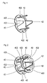
- Fig. 1 shows a disc-shaped stator plate 420 with adjoining claw poles 42.
- the claw poles are trapezoidal in shape to reduce the magnetic cogging torque.
- the disc-shaped stator plate 420 has V-shaped recesses in the region of the claw poles
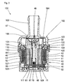
- Fig. 3 shows a sectional view through a centrifugal pump 100 according to the invention, comprising a pump housing 102, consisting of a first housing part 103 and an adjoining second housing part 104.
- a motor housing part 44 defines a drying space of a stator (40) of an electronically commutated DC motor and his control electronics is filled.
- the motor housing part 44 connects to the second housing part 102 and.
- the first and the second housing part 103, 104 define a wet space 101 of the centrifugal pump.
- the second housing part 104 is formed integrally with a containment shell 116 which divides the wet space 101 from a drying space 99.
- the wet room 101 includes an axle 49 which is fixedly installed between a cradle-side axle receptacle 48 and an intake-side axle receptacle 47. A knurling at the axis end prevents rotation of the axis 49 during pump operation.
- a fixed bearing 54 is rotatably mounted, which is pressed in a hollow shaft 51 of the rotor 50.
- the shaft 51 is integral with a pump impeller 59 which includes a plurality of approximately spirally shaped wings 591 for the fluid delivery.
- the end faces of the fixed bearing 54 can be supported axially with the interposition of thrust washers against the gap-side axle receptacle 48 and against the intake-side axle receptacle 47.
- a hollow cylindrical ferrite magnet 52 is adhered to the hollow shaft 51, using an elastic adhesive which is inserted into four or five axially parallel grooves 511 formed in the hollow shaft.
- the drying chamber 99 contains the stator 40 of the electronically commutated DC motor 10, which is designed in the form of a hollow cylindrical stator winding 41, wherein the magnetic field is guided in operation via claw poles in an alternating manner to the periphery of the can 116 and with the hollow cylindrical permanent magnet 52 in the wet space 101st interacts.
- the magnetic circuit is closed by a return ring 43, which is connected to disc-shaped stator laminations 420 with the claw poles 42.
- the claw poles 42 are provided by encapsulation with an insulating body 46 which connects the claw poles 42 mechanically but not magnetically.
- the stator 40 has four pole pairs in the present example.
- the Isolierstoff Sciences 46 is geometrically shaped so that the winding wires of the stator winding 41 are connected with clamping contact contacts having contact pins 62, said Klemmschneiduttone in Isolierstoff Sciences 46 are mechanically fastened.
- the contact pins 62 are formed as combi contacts and at its end opposite the clamping cutting contact 63 in a circuit board 61st pressed in and thus contacted with this.
- the contact pins 62 contain one or two deformable press-fit zones for this purpose.
- the circuit board 61 includes a Hall sensor 71, an integrated circuit 70 (IC) for wiring the stator winding, a PTC for the winding protection, and connector pins 64 for the power supply.
- the motor housing part 44 includes a connector housing 65 in which the connector pins 64 are arranged.
- Conductor tracks which serve for contacting components to be cooled, are dimensioned such that, for easier heat dissipation, conductor tracks 66 which are as wide as possible are provided on the printed circuit board 61.
- the different conductor tracks 66 are of different widths, depending on how much heat is generated in the component connection to be contacted.
- a longitudinal groove is formed as a cooling channel between a bottom 117 of the gap pot 116 and the pump impeller 59, which forces a continuous circulation of the fluid also in the interior of the containment shell 116.
- the printed circuit board is arranged between an end face 45 of the motor housing 44 and the bottom 117 of the can 116 and held in heat-conducting contact with the bottom 117 via the heat-conducting film 67.
- the first housing part 103 has a first flange 130 and a first adjoining ring 131.
- the second housing part 104 has a second flange 140 and a second adjoining ring 141.
- the motor housing part has a third ring 441.
- the second flange 140 and the second ring 141 together form a T-shape in cross-section.
- the first sealing region is located on the radially outer side of the first ring 131 on the first housing part 103.
- Opposite on the radially inner side of the second ring 141 and the second housing part 104 is the second sealing region 144.
- the third sealing region 145 is located on the radially outer side of the third ring 441 and the motor housing part 44.
- the second housing part 104 consists of one for laser light of one wavelength or a wavelength range permeable material.
- the first housing part 103 and the motor housing part 44 are made of a material absorbing the same laser light. This allows a laser beam without heating the transparent material to a seam lead. There the beam meets material, which absorbs the light and converts it to heat, causing the plastic to melt and intimately bond with the adjacent material.
- the welding apparatus may comprise two individual lasers, one weld being made with one laser beam at a time, or may comprise a single laser whose output beam is split by a beam splitter into two beams, each of which produces one of the welds.
- the laser beams are directed radially onto the pump housing.
- Fig. 4 shows a side view (from the right) of a tubular yoke ring 43, which is punched out of a sheet metal strip and rolled. The two ends of the sheet metal strip are connected together at an interface 437.
- the seam is formed here in the form of positive and button-like mating connecting means 438.
- the return ring has (here at its rear side) on the circumference of the yoke and arranged in its edge region slots 431, which are tapered towards its center and having at their ends radii.
- there are two slots 431 which are arranged in the same circumferential area but at opposite edges 435, 436.
- the two slots 431 are connected to each other through a connection slot 432 respectively extending from the center of the slots 431.
- the slits 431 and 432 together form an H-shape.
- the slots 431 each delimit a web 430 from the return body.
- FIGS. 4 and 6 show open slots 433 which are open to a recess 434.
- sheet metal tongues (439) are formed, which serve by radial bending (inwards) for the axial securing of the stator laminations 420.
- the metal bridges 430 are used both for axial securing of the stator laminations 420 and for reducing the diameter of the return path. By radially deforming the metal bridges 430, the connecting slot 432 is narrowed, if necessary, until the two edge regions of the connecting slot 432 touch each other.
- FIG. 5 shows a front view of the return ring 43 with the recess 434.
- FIG. 6 shows a spatial representation of the return ring 43 and FIG. 7 shows a side view (from the left).
Landscapes
- Engineering & Computer Science (AREA)
- Power Engineering (AREA)
- Iron Core Of Rotating Electric Machines (AREA)
Applications Claiming Priority (1)
| Application Number | Priority Date | Filing Date | Title |
|---|---|---|---|
| DE102006021246A DE102006021246A1 (de) | 2006-04-28 | 2006-04-28 | Elektromotor |
Publications (1)
| Publication Number | Publication Date |
|---|---|
| EP1850449A2 true EP1850449A2 (fr) | 2007-10-31 |
Family
ID=38139885
Family Applications (1)
| Application Number | Title | Priority Date | Filing Date |
|---|---|---|---|
| EP07008054A Withdrawn EP1850449A2 (fr) | 2006-04-28 | 2007-04-20 | Moteur électrique |
Country Status (2)
| Country | Link |
|---|---|
| EP (1) | EP1850449A2 (fr) |
| DE (1) | DE102006021246A1 (fr) |
Cited By (4)
| Publication number | Priority date | Publication date | Assignee | Title |
|---|---|---|---|---|
| EP3232543A1 (fr) * | 2016-04-15 | 2017-10-18 | Bühler Motor GmbH | Moteur de pompe comprenant un pot d'entrefer |
| US9976557B2 (en) | 2010-05-06 | 2018-05-22 | Bühler Motor GmbH | Pump having an integrated electronically commutated direct current motor |
| CN109338581A (zh) * | 2018-12-20 | 2019-02-15 | 北京爱尼机电有限公司 | 一种驱动针织大圆机运行的盘式电机传动装置 |
| CN110829665A (zh) * | 2018-08-14 | 2020-02-21 | 三花亚威科电器设备(芜湖)有限公司 | 定子组件、电机和泵 |
Families Citing this family (1)
| Publication number | Priority date | Publication date | Assignee | Title |
|---|---|---|---|---|
| CN103779981B (zh) * | 2014-01-24 | 2015-11-18 | 深圳市正德精密技术有限公司 | 一种直流无刷微电机 |
Family Cites Families (6)
| Publication number | Priority date | Publication date | Assignee | Title |
|---|---|---|---|---|
| DE8017528U1 (de) * | 1980-06-30 | 1981-03-26 | Siemens AG, 1000 Berlin und 8000 München | Synchronkleinmotor, insbesondere schrittmotor in klauenpolbauart |
| DE3514895A1 (de) * | 1985-04-25 | 1986-10-30 | Gerhard Berger GmbH & Co KG Fabrik elektrischer Geräte, 7630 Lahr | Schrittmotor sowie verfahren zur herstellung |
| DE19956380C1 (de) * | 1999-11-24 | 2001-01-04 | Bosch Gmbh Robert | Flüssigkeitspumpe mit einem Motorgehäuse und Verfahren zur Herstellung eines Motorgehäuses |
| JP2002354775A (ja) * | 2001-05-29 | 2002-12-06 | Minebea Co Ltd | クローポール型ステッピングモータのステータ構造 |
| DE10152497A1 (de) * | 2001-10-24 | 2003-05-15 | Pierburg Gmbh | Nassläuferpumpe |
| DE10226145A1 (de) * | 2002-06-13 | 2004-03-11 | Wilo Ag | Verfahren zur Montage eines Spalttopfmotors |
-
2006
- 2006-04-28 DE DE102006021246A patent/DE102006021246A1/de not_active Withdrawn
-
2007
- 2007-04-20 EP EP07008054A patent/EP1850449A2/fr not_active Withdrawn
Cited By (7)
| Publication number | Priority date | Publication date | Assignee | Title |
|---|---|---|---|---|
| US9976557B2 (en) | 2010-05-06 | 2018-05-22 | Bühler Motor GmbH | Pump having an integrated electronically commutated direct current motor |
| EP3232543A1 (fr) * | 2016-04-15 | 2017-10-18 | Bühler Motor GmbH | Moteur de pompe comprenant un pot d'entrefer |
| CN107299903A (zh) * | 2016-04-15 | 2017-10-27 | 标立电机有限公司 | 具有隔离罐的泵马达 |
| CN107299903B (zh) * | 2016-04-15 | 2020-07-10 | 标立电机有限公司 | 具有隔离罐的泵马达 |
| CN110829665A (zh) * | 2018-08-14 | 2020-02-21 | 三花亚威科电器设备(芜湖)有限公司 | 定子组件、电机和泵 |
| CN109338581A (zh) * | 2018-12-20 | 2019-02-15 | 北京爱尼机电有限公司 | 一种驱动针织大圆机运行的盘式电机传动装置 |
| CN109338581B (zh) * | 2018-12-20 | 2024-01-26 | 北京爱尼机电有限公司 | 一种驱动针织大圆机运行的盘式电机传动装置 |
Also Published As
| Publication number | Publication date |
|---|---|
| DE102006021246A1 (de) | 2007-10-31 |
Similar Documents
| Publication | Publication Date | Title |
|---|---|---|
| DE102006021242B4 (de) | Elektromotor | |
| DE102006021247B4 (de) | Elektromotor | |
| EP1850014B1 (fr) | Pompe centrifuge | |
| EP2182616B1 (fr) | Moteur à courant continu sans balai | |
| EP1648074B1 (fr) | Machine électrique, en particulier moteur à courant continu | |
| EP1850453A1 (fr) | Rotor à aimant permanent | |
| EP3078099B1 (fr) | Stator pour moteur à courant continu à commutation électronique | |
| EP1850010A2 (fr) | Pompe centrifuge | |
| EP3526884B1 (fr) | Procédé de mise en contact électrique d'un enroulement d'une machine électrique avec une carte de circuits imprimés | |
| EP0860930A2 (fr) | Moteur électrique pour une pompe ou un ventilateur | |
| DE10115852A1 (de) | Elektrische Umlaufvorrichtung sowie zugehöriges Herstellungsverfahren | |
| DE102011084763A1 (de) | Gehäuseteil für eine elektrische Maschine | |
| EP3593441A1 (fr) | Moteur électrique | |
| DE102009047485A1 (de) | Elektrische Maschine | |
| DE102008064131A1 (de) | Elektrische Maschine | |
| EP1850449A2 (fr) | Moteur électrique | |
| EP1372249A2 (fr) | Machine à flux transversal et plus particulièrement machine unipolaire à flux transversal | |
| DE112004001898T5 (de) | Kurzschlußteil, Kommutator und Verfahren zur Herstellung eines Kurzschlußteils | |
| EP2628237B1 (fr) | Rotor aux aimants permanents pour moteur électrique | |
| EP1524751B1 (fr) | Moteur électrique sans balai | |
| WO2005011084A1 (fr) | Dispositif, notamment machine electrique, comportant des elements constitutifs raccordes mutuellement par l'intermediaire d'un ajustement serre | |
| WO2000074204A2 (fr) | Stator d'un moteur a reluctance biphase a commutation electronique | |
| WO2020156829A1 (fr) | Pompe présentant une liaison directe du stator à la carte de circuits imprimés | |
| DE3607289A1 (de) | Anordnung einer eisenlosen wicklung in einem gleichstrommotor, insbesondere aussenlaeufermotor | |
| DE102016003044A1 (de) | Stator für eine Klauenpolmaschine |
Legal Events
| Date | Code | Title | Description |
|---|---|---|---|
| PUAI | Public reference made under article 153(3) epc to a published international application that has entered the european phase |
Free format text: ORIGINAL CODE: 0009012 |
|
| AK | Designated contracting states |
Kind code of ref document: A2 Designated state(s): AT BE BG CH CY CZ DE DK EE ES FI FR GB GR HU IE IS IT LI LT LU LV MC MT NL PL PT RO SE SI SK TR |
|
| AX | Request for extension of the european patent |
Extension state: AL BA HR MK YU |
|
| STAA | Information on the status of an ep patent application or granted ep patent |
Free format text: STATUS: THE APPLICATION HAS BEEN WITHDRAWN |
|
| 18W | Application withdrawn |
Effective date: 20071211 |