EP1850354A1 - Circulation cooling system for cryogenic cable - Google Patents
Circulation cooling system for cryogenic cable Download PDFInfo
- Publication number
- EP1850354A1 EP1850354A1 EP05719262A EP05719262A EP1850354A1 EP 1850354 A1 EP1850354 A1 EP 1850354A1 EP 05719262 A EP05719262 A EP 05719262A EP 05719262 A EP05719262 A EP 05719262A EP 1850354 A1 EP1850354 A1 EP 1850354A1
- Authority
- EP
- European Patent Office
- Prior art keywords
- refrigerant
- cable
- unit
- reserver
- heat exchange
- Prior art date
- Legal status (The legal status is an assumption and is not a legal conclusion. Google has not performed a legal analysis and makes no representation as to the accuracy of the status listed.)
- Granted
Links
Images

Classifications
-
- H—ELECTRICITY
- H01—ELECTRIC ELEMENTS
- H01B—CABLES; CONDUCTORS; INSULATORS; SELECTION OF MATERIALS FOR THEIR CONDUCTIVE, INSULATING OR DIELECTRIC PROPERTIES
- H01B12/00—Superconductive or hyperconductive conductors, cables, or transmission lines
- H01B12/16—Superconductive or hyperconductive conductors, cables, or transmission lines characterised by cooling
-
- H—ELECTRICITY
- H02—GENERATION; CONVERSION OR DISTRIBUTION OF ELECTRIC POWER
- H02G—INSTALLATION OF ELECTRIC CABLES OR LINES, OR OF COMBINED OPTICAL AND ELECTRIC CABLES OR LINES
- H02G15/00—Cable fittings
- H02G15/34—Cable fittings for cryogenic cables
Definitions
- the present invention relates to a circulation cooling system of a cryogenic cable such as a superconducting cable.
- Cryogenic cables such as a superconducting cable are cooled down by a refrigerant such as liquid nitrogen or liquid helium.
- a refrigerant such as liquid nitrogen or liquid helium.
- a circulation cooling system for such cables a system described in Japanese Patent Laying-Open No. 8-148044 is known, for example.
- a circulation circuit of the refrigerant is a closed circuit and the refrigerant can be circulated in the state where the refrigerant is not vaporized.
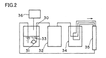
- Fig. 2 schematically shows the system.
- the system includes a reserver unit 30 that stores a refrigerant 33, a pressure-feed pump 31 that pressure-feeds refrigerant 33, a pressure control device 36 that keeps a predetermined pressure within reserver unit 30, a heat exchange unit 32 that cools down refrigerant 33 to a predetermined temperature, a valve unit 34 that splits refrigerant 33 into a cable 35 (three cables exist and each cable is not shown) and the like.
- the system repeats the cycle in which refrigerant 33 sent from reserver unit 30 is cooled down to the predetermined temperature at heat exchange unit 32 and is supplied to cable 35 and then returned to reserver unit 30.
- Patent Document 1 Japanese Patent Laying-Open No. 8-148044 (Claims and Fig. 1)
- reserver unit 30 is upstream of the circulation circuit and refrigerant 33 sent from reserver unit 30 is sent toward cable 35 after cooled down to the predetermined temperature at heat exchange unit 32. That is, since refrigerant 33 is returned to reserver unit 30 after cooling down cable 35, refrigerant 33 is raised in temperature due to heat generation at cable 35 and increases in volume due to heat expansion.
- refrigerant 33 changes in volume as well.
- refrigerant 33 needs to be sufficiently cooled down, correspondingly.
- refrigerant 33 contracts and decreases in volume.
- refrigerant 33 expands or contracts in volume due to the change in the temperature of refrigerant 33 and changes in liquid volume while the volume of each component other than reserver unit 30 such as a cooling portion of cable 35 and a piping is constant, the change in the liquid volume of the refrigerant needs to be absorbed within the capacity in reserver unit 30. Accordingly, the refrigerant storing capacity of resever unit 30 has to be designed to absorb the change in liquid volume of the refrigerant, and as a result, reserver unit 30 needs to have a large capacity. Alternatively, in order to keep the amount of the refrigerant within reserver unit 30 constant, it has been necessary to provide an adjustment mechanism of the refrigerant amount for an adjustment task.
- the reserver unit needs to have a large capacity or a refrigerant amount adjustment mechanism of a large capacity is needed, considering the expansion and contraction of volume.
- One object of the present invention is to provide a circulation cooling system of a cryogenic cable that solves the problems of the conventional circulation cooling system and is capable of making a reserver unit smaller and does not need an adjustment mechanism or an adjustment task of the amount of the refrigerant within the reserver unit.
- a circulation cooling system of a cryogenic cable according to the present invention is characterized in that the system has a refrigerant temperature adjustment mechanism to keep constant the amount of the refrigerant within a reserver unit to achieve the object.
- the circulation cooling system of a cryogenic cable has a reserver unit storing a refrigerant and a cable cooling portion cooling down a cable by the refrigerant sent from the reserver unit and the refrigerant sent from the cable cooling portion is returned to the reserver unit again for circulation.
- the system is characterized in that it has a refrigerant temperature adjustment mechanism to keep constant the amount of the refrigerant within the reserver unit.
- the refrigerant temperature adjustment mechanism may include a sensor detecting the refrigerant temperature and a heat exchange unit adjusting the cooling capacity according to the detecting result of the sensor.
- the sensor detecting the refrigerant temperature may be located close to a refrigerant exit of the cable cooling portion.
- the heat exchange unit may be located between the refrigerant exit of the cable cooling portion and a refrigerant return inlet to the reserver unit.
- adjustment of the cooling capacity of the heat exchange unit may be performed by adjustment of the power for operating the heat exchange unit or the power supply frequency.
- the circulation cooling system of a cryogenic cable has the refrigerant temperature adjustment mechanism to keep the amount of the refrigerant within the reserver unit constant, it is not necessary to add volume to the reserver unit to absorb the change in the volume of the refrigerant, leading to a smaller reserver unit. Further, a mechanism or a task to adjust the refrigerant volume within the reserver unit is unnecessary.
- the cooling capacity of the heat exchange unit can be adjusted more securely according to the change in heat generation of the cable while the change in the volume of the refrigerant due to heat generation of the cable can be prevented from directly affecting the reserver unit side. Therefore, the amount of the refrigerant within the reserver unit can be kept constant more correctly.
- the heat exchange unit consumes less energy compared to a conventional system which is always operated at full power and adjusts the temperature by heating with a heater when cooling is excessive, leading to energy conservation.
- a refrigerant temperature adjustment mechanism to keep constant the amount of a refrigerant within a reserver unit has a function to keep constant the refrigerant temperature within a system.
- a representative example of the mechanism is one including a sensor detecting the refrigerant temperature and a heat exchange unit adjusting the cooling capacity according to the detecting result of the sensor.
- the refrigerant temperature is kept constant by increasing (when the temperature is to be lowered) or decreasing (when the temperature is to be increased) the cooling capacity of the heat exchange unit according to the change in the refrigerant temperature detected by the sensor.
- the sensor detecting the refrigerant temperature may be any type if the sensor can provide sensitive and correct detection even at a cryogenic temperature. In a circulation cooling system of a cryogenic cable according to the present invention, it is usually the change in the amount of heat generation at the cable that affects the change in the refrigerant temperature most. Thus, preferably, the sensor is provided close to the exit of the cable cooling portion since the change in the amount of heat generation at the cable can be detected quickly and sensitive adjustment of the refrigerant temperature can be achieved.
- the heat exchange unit may be also any type if the unit has sufficient cooling capacity and can provide adjustment of the cooling capacity according to the change in the refrigerant temperature.
- a method of adjusting the cooling capacity is not limited particularly and a method commonly used in a conventional cooling system, i.e. the method in which a heat exchange unit having full power larger than the power corresponding to the expected maximum amount of change in the refrigerant temperature is always operated at full power and adjustment is performed by heating with a heater located at the heat exchange unit when the refrigerant temperature is lowered too much, can be employed.
- adjustment of the cooling capacity is performed by adjustment of the power for operating the heat exchange unit or the power supply frequency, since heating with a heater is unnecessary and energy required for cooling (power consumption) can be reduced.
- the adjustment of the power supply frequency is performed by an inverter, for example.
- the cooling capacity of the heat exchange unit is dependent on the frequency. For example, when 60 Hz operation is changed to 30 Hz operation, the cooling capacity will be one half
- the refrigerant is sent from the reserver unit to the cable cooling portion.
- the heat exchange unit may be provided between the reserver unit and the cable cooling portion.
- the cable cooling portion i.e. the heat generating portion is downstream of the heat exchange unit
- swift adjustment of the refrigerant temperature according to the change in the amount of heat generation at the cable hence swift adjustment according to the change in the volume of the refrigerant based on the change in the refrigerant temperature cannot be achieved. That is, even when the refrigerant temperature changes due to the change in the amount of heat generation at the cable, and as a result, the volume of the refrigerant increases or decreases, the refrigerant itself that has been increased or decreased in volume cannot be directly adjusted in temperature and it is impossible to address the change in the volume of the refrigerant swiftly. Consequently, sensitive adjustment is difficult.
- the heat exchange unit is provided between the refrigerant exit of the cable cooling portion and the refrigerant return inlet to the reserver unit. More preferably, the sensor detecting the refrigerant temperature is located close to the exit of the cable cooling portion and the heat exchange unit is provided between the refrigerant exit of the cable cooling portion and the refrigerant return inlet to the reserver unit.
- the system in Fig. 1 includes a reserver unit 1, a heat exchange unit 2, a valve unit 3, a cable cooling portion 4 and a sensor 5 detecting the refrigerant temperature (hereinafter referred to as sensor 5) as its main components.
- Reserver unit 1 is a closed container to store a refrigerant C and includes a pressure-feed pump 7 to circulate the refrigerant and a pressure control device 9.
- Refrigerant C is pressurized by pressure-feed pump 7 for circulation, and its discharge pressure is adjusted by a bypass valve 8 within the reserver unit.
- a pump is used that can provide necessary flow rate even in a case where the refrigerant pressure decreases in the circulation circuit.
- Pressure-feed pump 7 may be provided independently outside reserver unit 1. However, when the pump is provided within reserver unit 1 as in the present example, a vacuum insulated container can be shared and manufacturing cost of the system can be reduced. It is to be noted that P1 is a pressure gauge to measure the pressure within reserver unit 1, P2 is a pressure gauge to measure the pressure at the discharge portion of pressure-feed pump 7, 20 is a safety valve to protect reserver unit 1 from excessive rise in pressure and 21 is a check valve to prevent the air or the like from entering reserver unit 1.
- Pressure control device 9 supplies a gas G to keep the pressure within reserver unit 1 almost constant and keep refrigerant C in a state where the refrigerant is not vaporized.
- the pressure control device is not essential in the present invention.
- gas G to be supplied a gas having a lower boiling point or triple point than refrigerant C is used.
- refrigerant C is liquid nitrogen, for example, helium is used.
- an automatic refrigerant supply mechanism (combination of a liquid level gauge and a supplier operating according to the measurement result) to maintain the amount of the refrigerant within reserver unit 1 constant may be provided.
- this mechanism is basically unnecessary.
- Valve unit 3 has a function to split refrigerant C sent from reserver unit 1 through a piping 15 to supply to cable cooling portion 4.
- refrigerant C is divided into three branches and a flow meter 12, a flow rate adjustment valve 13 and a bypass valve 14 are provided for a respective branch.
- Refrigerant C sent through valve unit 3 is supplied to cable cooling portion 4.
- refrigerant C is supplied from one end of cable cooling portion 4 and at the other end, the three branches of refrigerant C corresponding to three phases are combined into one flow for discharge and then returned to heat exchange unit 2 side.
- respective cable is cooled down by refrigerant C while refrigerant C is increased in temperature due to heat generation of the cable.
- the amount of the increase in temperature varies depending on the change in the amount of heat generation of the cable (i.e. the change in current).
- Sensor 5 provided close to the refrigerant exit of cable cooling portion 4 detects the temperature of refrigerant C and the measurement result is fed back to a power adjustment machine 23 of heat exchange unit 2. Refrigerant C sent from sensor 5 is sent to heat exchange unit 2 through a piping 16.
- Heat exchange unit 2 cools down refrigerant C sent from sensor 5 to a predetermined temperature.
- a cold head 11 of a refrigerating machine 10 is kept in contact with a Cu block and a transport pipe of refrigerant C is wound around the Cu block for heat exchange by solid heat conduction.
- one heat exchange unit 2 is used in the present example, two or more units may be connected in series when the cooling capacity of one unit is not sufficient.
- heat exchange unit 2 is provided downstream of the exit side piping 16 of sensor 5 and upstream of a return piping to reserver unit 1 of refrigerant C. That is, the unit is located between the refrigerant exit of cable cooling portion 4 and the refrigerant return inlet to reserver unit 1.
- Refrigerating machine 10 is supplied with power for operation from a power supply 22 for the heat exchange unit. Between power supply 22 and refrigerating machine 10 is provided a power adjustment machine 23 for operating the heat exchange unit. As described above, the temperature detected by sensor 5 is fed back and power adjustment machine 23 is controlled. Thus, the cooling capacity of heat exchange unit 2 is adjusted and the temperature of the return inlet to reserver unit 1 is controlled to be constant while the change in the volume of refrigerant C due to the change in the temperature of refrigerant C is prevented.
- an inverter capable of arbitrarily changing the power supply frequency input to heat exchange unit 2 may be used.
- Refrigerant C sent from heat exchange unit 2 is returned to resever unit 1 through piping 15.
- each unit 1, 2, 3, 15 and 16 may be vacuum insulated collectively, not separately.
- the circulation cooling system of a cryogenic cable according to the present invention is used as a cooling system of a cable such as a superconducting cable that is used in a condition cooled down by a refrigerant.
- the system is particularly useful when dowinsizing or simplification of the mechanism is required.
Abstract
Description
- The present invention relates to a circulation cooling system of a cryogenic cable such as a superconducting cable.
- Cryogenic cables such as a superconducting cable are cooled down by a refrigerant such as liquid nitrogen or liquid helium. As a circulation cooling system for such cables, a system described in
Japanese Patent Laying-Open No. 8-148044 - Fig. 2 schematically shows the system. The system includes a
reserver unit 30 that stores arefrigerant 33, a pressure-feed pump 31 that pressure-feeds refrigerant 33, apressure control device 36 that keeps a predetermined pressure withinreserver unit 30, aheat exchange unit 32 that cools downrefrigerant 33 to a predetermined temperature, avalve unit 34 that splits refrigerant 33 into a cable 35 (three cables exist and each cable is not shown) and the like. - The system repeats the cycle in which
refrigerant 33 sent fromreserver unit 30 is cooled down to the predetermined temperature atheat exchange unit 32 and is supplied tocable 35 and then returned to reserverunit 30. - Patent Document 1:
Japanese Patent Laying-Open No. 8-148044 - In the above-mentioned conventional circulation cooling system, however, with respect to
cable 35,reserver unit 30 is upstream of the circulation circuit andrefrigerant 33 sent fromreserver unit 30 is sent towardcable 35 after cooled down to the predetermined temperature atheat exchange unit 32. That is, sincerefrigerant 33 is returned to reserverunit 30 after cooling downcable 35,refrigerant 33 is raised in temperature due to heat generation atcable 35 and increases in volume due to heat expansion. - Correspondingly to the change in the amount of heat generation at
cable 35, refrigerant 33 changes in volume as well. When large heat generation atcable 35 is expected, for example,refrigerant 33 needs to be sufficiently cooled down, correspondingly. In this case, conversely, refrigerant 33 contracts and decreases in volume. - Thus, since
refrigerant 33 expands or contracts in volume due to the change in the temperature ofrefrigerant 33 and changes in liquid volume while the volume of each component other thanreserver unit 30 such as a cooling portion ofcable 35 and a piping is constant, the change in the liquid volume of the refrigerant needs to be absorbed within the capacity inreserver unit 30. Accordingly, the refrigerant storing capacity of reseverunit 30 has to be designed to absorb the change in liquid volume of the refrigerant, and as a result,reserver unit 30 needs to have a large capacity. Alternatively, in order to keep the amount of the refrigerant withinreserver unit 30 constant, it has been necessary to provide an adjustment mechanism of the refrigerant amount for an adjustment task. Especially when the total amount of the refrigerant within the system is large or the system has a large temperature change, the reserver unit needs to have a large capacity or a refrigerant amount adjustment mechanism of a large capacity is needed, considering the expansion and contraction of volume. - One object of the present invention is to provide a circulation cooling system of a cryogenic cable that solves the problems of the conventional circulation cooling system and is capable of making a reserver unit smaller and does not need an adjustment mechanism or an adjustment task of the amount of the refrigerant within the reserver unit.
- A circulation cooling system of a cryogenic cable according to the present invention is characterized in that the system has a refrigerant temperature adjustment mechanism to keep constant the amount of the refrigerant within a reserver unit to achieve the object.
- Specifically, the circulation cooling system of a cryogenic cable according to the present invention has a reserver unit storing a refrigerant and a cable cooling portion cooling down a cable by the refrigerant sent from the reserver unit and the refrigerant sent from the cable cooling portion is returned to the reserver unit again for circulation. The system is characterized in that it has a refrigerant temperature adjustment mechanism to keep constant the amount of the refrigerant within the reserver unit.
- In the circulation cooling system of a cryogenic cable, the refrigerant temperature adjustment mechanism may include a sensor detecting the refrigerant temperature and a heat exchange unit adjusting the cooling capacity according to the detecting result of the sensor.
- In the circulation cooling system of a cryogenic cable, the sensor detecting the refrigerant temperature may be located close to a refrigerant exit of the cable cooling portion.
- In the circulation cooling system of a cryogenic cable, the heat exchange unit may be located between the refrigerant exit of the cable cooling portion and a refrigerant return inlet to the reserver unit.
- In the circulation cooling system of a cryogenic cable, adjustment of the cooling capacity of the heat exchange unit may be performed by adjustment of the power for operating the heat exchange unit or the power supply frequency.
- Since the circulation cooling system of a cryogenic cable according to the present invention has the refrigerant temperature adjustment mechanism to keep the amount of the refrigerant within the reserver unit constant, it is not necessary to add volume to the reserver unit to absorb the change in the volume of the refrigerant, leading to a smaller reserver unit. Further, a mechanism or a task to adjust the refrigerant volume within the reserver unit is unnecessary.
- When the sensor detecting the refrigerant temperature is located close to the exit of the cable cooling portion and the heat exchange unit is provided between the refrigerant exit of the cable cooling portion and the refrigerant return inlet to the reserver unit, the cooling capacity of the heat exchange unit can be adjusted more securely according to the change in heat generation of the cable while the change in the volume of the refrigerant due to heat generation of the cable can be prevented from directly affecting the reserver unit side. Therefore, the amount of the refrigerant within the reserver unit can be kept constant more correctly.
- Further, when adjustment of the cooling capacity of the heat exchange unit is performed by adjustment of the power for operating the heat exchange unit or the power supply frequency, the heat exchange unit consumes less energy compared to a conventional system which is always operated at full power and adjusts the temperature by heating with a heater when cooling is excessive, leading to energy conservation.
-
- Fig. 1 schematically shows an example of a circulation cooling system of a cryogenic cable of the present invention.
- Fig. 2 schematically shows an example of a conventional circulation cooling system of a cryogenic cable.
- 1, 30: reserver unit, 2, 32 : heat exchange unit, 3, 34: valve unit, 4: cable cooling portion, 5: sensor, 7, 31: pressure-feed pump, 8: bypass valve, 9, 36: pressure control device, 10: refrigerating machine, 11: cold head, 12: flow meter, 13: flow rate adjustment valve, 14: bypass valve, 15,16: piping, 18: vacuum insulated container, 20: safety valve, 21: check valve, 22: power supply, 23: power adjustment machine, C: refrigerant, G: gas, P1, P2: pressure gauge
- A refrigerant temperature adjustment mechanism to keep constant the amount of a refrigerant within a reserver unit has a function to keep constant the refrigerant temperature within a system. A representative example of the mechanism is one including a sensor detecting the refrigerant temperature and a heat exchange unit adjusting the cooling capacity according to the detecting result of the sensor. The refrigerant temperature is kept constant by increasing (when the temperature is to be lowered) or decreasing (when the temperature is to be increased) the cooling capacity of the heat exchange unit according to the change in the refrigerant temperature detected by the sensor.
- The sensor detecting the refrigerant temperature may be any type if the sensor can provide sensitive and correct detection even at a cryogenic temperature. In a circulation cooling system of a cryogenic cable according to the present invention, it is usually the change in the amount of heat generation at the cable that affects the change in the refrigerant temperature most. Thus, preferably, the sensor is provided close to the exit of the cable cooling portion since the change in the amount of heat generation at the cable can be detected quickly and sensitive adjustment of the refrigerant temperature can be achieved.
- The heat exchange unit may be also any type if the unit has sufficient cooling capacity and can provide adjustment of the cooling capacity according to the change in the refrigerant temperature. Further, a method of adjusting the cooling capacity is not limited particularly and a method commonly used in a conventional cooling system, i.e. the method in which a heat exchange unit having full power larger than the power corresponding to the expected maximum amount of change in the refrigerant temperature is always operated at full power and adjustment is performed by heating with a heater located at the heat exchange unit when the refrigerant temperature is lowered too much, can be employed. However, preferably, adjustment of the cooling capacity is performed by adjustment of the power for operating the heat exchange unit or the power supply frequency, since heating with a heater is unnecessary and energy required for cooling (power consumption) can be reduced.
- The adjustment of the power supply frequency is performed by an inverter, for example. The cooling capacity of the heat exchange unit is dependent on the frequency. For example, when 60 Hz operation is changed to 30 Hz operation, the cooling capacity will be one half
- In the circulation cooling system of a cryogenic cable according to the present invention, the refrigerant is sent from the reserver unit to the cable cooling portion. When the sensor detecting the refrigerant temperature is located close to the exit of the cable cooling portion, for example, the heat exchange unit may be provided between the reserver unit and the cable cooling portion. When heat generation at the cable is large and the temperature close to the exit of the cable cooling portion is increased, the cooling capacity of the heat exchange unit can be increased and the increase in the refrigerant temperature can be suppressed.
- However, in this case, since the cable cooling portion, i.e. the heat generating portion is downstream of the heat exchange unit, swift adjustment of the refrigerant temperature according to the change in the amount of heat generation at the cable, hence swift adjustment according to the change in the volume of the refrigerant based on the change in the refrigerant temperature cannot be achieved. That is, even when the refrigerant temperature changes due to the change in the amount of heat generation at the cable, and as a result, the volume of the refrigerant increases or decreases, the refrigerant itself that has been increased or decreased in volume cannot be directly adjusted in temperature and it is impossible to address the change in the volume of the refrigerant swiftly. Consequently, sensitive adjustment is difficult.
- Thus, preferably, the heat exchange unit is provided between the refrigerant exit of the cable cooling portion and the refrigerant return inlet to the reserver unit. More preferably, the sensor detecting the refrigerant temperature is located close to the exit of the cable cooling portion and the heat exchange unit is provided between the refrigerant exit of the cable cooling portion and the refrigerant return inlet to the reserver unit. In this manner, adjustment of the cooling capacity of the heat exchange unit directly addressing the change in heat generation at the cable can be achieved while the amount of the refrigerant within the reserver unit can be kept constant more correctly without direct influence, on the reserver unit, of the change in the volume of the refrigerant due to heat expansion or heat contraction, since the refrigerant cooled down to a predetermined temperature at the heat exchange unit is supplied to the reserver unit.
- In the following, the more preferable manner will be described more specifically referring to Fig. 1.
- The system in Fig. 1 includes a reserver unit 1, a
heat exchange unit 2, avalve unit 3, a cable cooling portion 4 and a sensor 5 detecting the refrigerant temperature (hereinafter referred to as sensor 5) as its main components. - Reserver unit 1 is a closed container to store a refrigerant C and includes a pressure-
feed pump 7 to circulate the refrigerant and a pressure control device 9. Refrigerant C is pressurized by pressure-feed pump 7 for circulation, and its discharge pressure is adjusted by a bypass valve 8 within the reserver unit. For pressure-feed pump 7, a pump is used that can provide necessary flow rate even in a case where the refrigerant pressure decreases in the circulation circuit. - Pressure-
feed pump 7 may be provided independently outside reserver unit 1. However, when the pump is provided within reserver unit 1 as in the present example, a vacuum insulated container can be shared and manufacturing cost of the system can be reduced. It is to be noted that P1 is a pressure gauge to measure the pressure within reserver unit 1, P2 is a pressure gauge to measure the pressure at the discharge portion of pressure-feed pump - Pressure control device 9 supplies a gas G to keep the pressure within reserver unit 1 almost constant and keep refrigerant C in a state where the refrigerant is not vaporized. The pressure control device, however, is not essential in the present invention. For gas G to be supplied, a gas having a lower boiling point or triple point than refrigerant C is used. When refrigerant C is liquid nitrogen, for example, helium is used.
- In the conventional circulation cooling system described above, an automatic refrigerant supply mechanism (combination of a liquid level gauge and a supplier operating according to the measurement result) to maintain the amount of the refrigerant within reserver unit 1 constant may be provided. However, in the present invention, this mechanism is basically unnecessary.
-
Valve unit 3 has a function to split refrigerant C sent from reserver unit 1 through a piping 15 to supply to cable cooling portion 4. In the present example, in order to supply refrigerant C uniformly to three-phase power cables located within cable cooling portion 4, refrigerant C is divided into three branches and aflow meter 12, a flowrate adjustment valve 13 and abypass valve 14 are provided for a respective branch. - Refrigerant C sent through
valve unit 3 is supplied to cable cooling portion 4. In the present example, refrigerant C is supplied from one end of cable cooling portion 4 and at the other end, the three branches of refrigerant C corresponding to three phases are combined into one flow for discharge and then returned toheat exchange unit 2 side. - Within cable cooling portion 4, respective cable is cooled down by refrigerant C while refrigerant C is increased in temperature due to heat generation of the cable. The amount of the increase in temperature varies depending on the change in the amount of heat generation of the cable (i.e. the change in current).
- Sensor 5 provided close to the refrigerant exit of cable cooling portion 4 detects the temperature of refrigerant C and the measurement result is fed back to a
power adjustment machine 23 ofheat exchange unit 2. Refrigerant C sent from sensor 5 is sent to heatexchange unit 2 through apiping 16. -
Heat exchange unit 2 cools down refrigerant C sent from sensor 5 to a predetermined temperature. In the present example, a cold head 11 of a refrigeratingmachine 10 is kept in contact with a Cu block and a transport pipe of refrigerant C is wound around the Cu block for heat exchange by solid heat conduction. Further, although oneheat exchange unit 2 is used in the present example, two or more units may be connected in series when the cooling capacity of one unit is not sufficient. - In the present example,
heat exchange unit 2 is provided downstream of the exit side piping 16 of sensor 5 and upstream of a return piping to reserver unit 1 of refrigerant C. That is, the unit is located between the refrigerant exit of cable cooling portion 4 and the refrigerant return inlet to reserver unit 1. - Refrigerating
machine 10 is supplied with power for operation from apower supply 22 for the heat exchange unit. Betweenpower supply 22 and refrigeratingmachine 10 is provided apower adjustment machine 23 for operating the heat exchange unit. As described above, the temperature detected by sensor 5 is fed back andpower adjustment machine 23 is controlled. Thus, the cooling capacity ofheat exchange unit 2 is adjusted and the temperature of the return inlet to reserver unit 1 is controlled to be constant while the change in the volume of refrigerant C due to the change in the temperature of refrigerant C is prevented. Forpower adjustment machine 23, an inverter capable of arbitrarily changing the power supply frequency input to heatexchange unit 2 may be used. - It is to be noted that when the amount of the refrigerant existing between the heat generating portion, i.e. cable cooling portion 4 and
heat exchange unit 2 is large, the change in the volume of the refrigerant due to heat expansion or heat contraction of the refrigerant becomes large. Accordingly, it is preferable that this amount of the refrigerant is small andheat exchange unit 2 is located close to the refrigerant exit of cable cooling portion 4, i.e. close to the exit of sensor 5. - Refrigerant C sent from
heat exchange unit 2 is returned to resever unit 1 throughpiping 15. - Reserver unit 1,
heat exchange unit 2 andvalve unit 3 are separately housed in a vacuum insulatedcontainer 18 andpipings unit - The circulation cooling system of a cryogenic cable according to the present invention is used as a cooling system of a cable such as a superconducting cable that is used in a condition cooled down by a refrigerant. The system is particularly useful when dowinsizing or simplification of the mechanism is required.
Claims (5)
- A circulation cooling system of a cryogenic cable having a reserver unit (1) storing a refrigerant and a cable cooling portion (4) cooling down a cable by the refrigerant sent from said reserver unit (1), the system returning the refrigerant sent from said cable cooling portion (4) to said reserver unit (1) again for circulation,
wherein the system has a refrigerant temperature adjustment mechanism (2, 5) to keep constant an amount of the refrigerant within said reserver unit (1). - The circulation cooling system of a cryogenic cable according to claim 1,
wherein said refrigerant temperature adjustment mechanism (2, 5) includes a sensor (5) detecting a temperature of the refrigerant and a heat exchange unit (2) adjusting a cooling capacity according to a detecting result of said sensor (5). - The circulation cooling system of a cryogenic cable according to claim 2,
wherein said sensor (5) detecting said temperature of the refrigerant is located close to a refrigerant exit of said cable cooling portion (4). - The circulation cooling system of a cryogenic cable according to claim 2,
wherein said heat exchange unit (2) is located between a refrigerant exit of said cable cooling portion (4) and a refrigerant return inlet to said reserver unit (1). - The circulation cooling system of a cryogenic cable according to claim 2,
wherein adjustment of the cooling capacity of said heat exchange unit (2) is performed by adjustment of power for operating said heat exchange unit or power supply frequency.
Applications Claiming Priority (1)
| Application Number | Priority Date | Filing Date | Title |
|---|---|---|---|
| PCT/JP2005/002543 WO2006087794A1 (en) | 2005-02-18 | 2005-02-18 | Circulation cooling system for cryogenic cable |
Publications (3)
| Publication Number | Publication Date |
|---|---|
| EP1850354A1 true EP1850354A1 (en) | 2007-10-31 |
| EP1850354A4 EP1850354A4 (en) | 2011-04-20 |
| EP1850354B1 EP1850354B1 (en) | 2012-06-20 |
Family
ID=36916210
Family Applications (1)
| Application Number | Title | Priority Date | Filing Date |
|---|---|---|---|
| EP05719262A Expired - Lifetime EP1850354B1 (en) | 2005-02-18 | 2005-02-18 | Circulation cooling system for cryogenic cable |
Country Status (7)
| Country | Link |
|---|---|
| US (1) | US7854132B2 (en) |
| EP (1) | EP1850354B1 (en) |
| KR (1) | KR101099899B1 (en) |
| CN (1) | CN1942979B (en) |
| CA (1) | CA2563873A1 (en) |
| NO (1) | NO20064718L (en) |
| WO (1) | WO2006087794A1 (en) |
Cited By (4)
| Publication number | Priority date | Publication date | Assignee | Title |
|---|---|---|---|---|
| DE102012016292A1 (en) | 2012-08-16 | 2014-02-20 | Messer Group Gmbh | Method and device for cooling objects |
| DE102018001040A1 (en) | 2018-02-08 | 2019-08-08 | Messer Group Gmbh | Method and apparatus for cooling a superconducting current carrier |
| WO2020043340A1 (en) | 2018-08-30 | 2020-03-05 | Messer Group Gmbh | Device for cooling a superconducting element |
| DE102020007043A1 (en) | 2020-11-18 | 2022-05-19 | Messer Se & Co. Kgaa | Device for transmitting electrical energy with a superconducting current carrier |
Families Citing this family (12)
| Publication number | Priority date | Publication date | Assignee | Title |
|---|---|---|---|---|
| KR100893047B1 (en) * | 2008-01-25 | 2009-04-15 | 엘에스전선 주식회사 | Superconducting cable |
| KR101027535B1 (en) * | 2010-08-25 | 2012-04-18 | 엘아이지넥스원 주식회사 | Demagnetization system for naval vessel using superconducting wire |
| KR101333040B1 (en) * | 2012-01-02 | 2013-11-26 | 한국에너지기술연구원 | Apparatus and method for measuring concentration of nonazeotrope refrigerant mixture, and absorption type, 1-stage compressing-absorbing type and 2-stage compression-absorption type heat pump having the same |
| CN102661485B (en) * | 2012-04-25 | 2014-04-02 | 江苏美时医疗技术有限公司 | Liquid nitrogen filling device and liquid nitrogen filling system |
| CN102881381A (en) * | 2012-09-27 | 2013-01-16 | 张家港韩中深冷科技有限公司 | Superconducting cable cooling system |
| KR102001250B1 (en) * | 2013-07-12 | 2019-07-19 | 한국전력공사 | Heat exchanger with multi flow path |
| CN104064279A (en) * | 2014-06-13 | 2014-09-24 | 苏州华徕光电仪器有限公司 | Cooling system for cold insulation superconducting cable |
| CN104064280A (en) * | 2014-06-13 | 2014-09-24 | 苏州华徕光电仪器有限公司 | Superconducting cable circulating cooling system |
| CN105355319B (en) * | 2015-12-03 | 2018-01-19 | 中国电力科学研究院 | A kind of cryostat for hyperconductive cable |
| US10398153B2 (en) * | 2016-06-30 | 2019-09-03 | Miguel Angel Fernandez | Liquid nitrogen dispenser for frozen treats |
| CN109297254A (en) * | 2018-09-10 | 2019-02-01 | 成都深冷液化设备股份有限公司 | Using low temperature refrigerator group as the charging cable gas circulating cooling method of cold source |
| CN109323496A (en) * | 2018-09-10 | 2019-02-12 | 成都深冷液化设备股份有限公司 | Using liquid nitrogen or liquid air as the charging cable gas circulating cooling method of cold source |
Family Cites Families (15)
| Publication number | Priority date | Publication date | Assignee | Title |
|---|---|---|---|---|
| US3646243A (en) * | 1969-10-27 | 1972-02-29 | Simplex Wire & Cable Co | Coolant circuit for resistive cryogenic electric power transmission line |
| SU508336A1 (en) | 1973-03-05 | 1976-03-30 | Предприятие П/Я Г-4158 | The method of regulating the heat regime of the mold |
| US3851274A (en) * | 1973-06-29 | 1974-11-26 | Atomic Energy Commission | Recirculating liquid-nitrogen-coolant system for solid-state lasers |
| SU1097979A1 (en) | 1982-08-02 | 1984-06-15 | Одесское специальное конструкторское бюро полиграфического машиностроения | System for thermostatting solutions |
| US5199274A (en) * | 1991-06-17 | 1993-04-06 | Matsushita Electric Industrial Co., Ltd. | Automotive air conditioning apparatus |
| US5402648A (en) * | 1993-07-01 | 1995-04-04 | Apd Cryogenics Inc. | Sealed dewar with separate circulation loop for external cooling at constant pressure |
| JP3648731B2 (en) | 1994-11-22 | 2005-05-18 | 住友電気工業株式会社 | Cryogenic cooling system for cryogenic cables |
| JP3596090B2 (en) * | 1995-06-06 | 2004-12-02 | 株式会社デンソー | Vehicle air conditioner |
| JP3818328B2 (en) | 1996-10-02 | 2006-09-06 | 住友電気工業株式会社 | Cryogenic cable cooling apparatus and cooling method |
| DK174179B1 (en) * | 2000-03-13 | 2002-08-19 | Lars Zimmermann | Circuit with capillary tube droplet and refrigerant tank |
| JP3511288B2 (en) | 2000-03-31 | 2004-03-29 | 大陽東洋酸素株式会社 | Superconducting material cooling device |
| JP2002071237A (en) * | 2000-08-25 | 2002-03-08 | Sharp Corp | Stirling cooling system and cooling compartment |
| RU17819U1 (en) | 2000-10-18 | 2001-04-27 | Федеральное государственное унитарное предприятие "Производственное объединение "Уральский оптико-механический завод" | SOLID LASER THERMOSTABILIZATION SYSTEM |
| ITTO20030792A1 (en) * | 2002-10-08 | 2004-04-09 | Danfoss As | VALVE CONTROL DEVICE AND PROCEDURE |
| US20040144110A1 (en) * | 2003-01-27 | 2004-07-29 | Reeves Hazel Dickerson | Evaporative cooling system |
-
2005
- 2005-02-18 WO PCT/JP2005/002543 patent/WO2006087794A1/en not_active Ceased
- 2005-02-18 CN CN2005800110119A patent/CN1942979B/en not_active Expired - Fee Related
- 2005-02-18 CA CA002563873A patent/CA2563873A1/en not_active Abandoned
- 2005-02-18 US US11/578,527 patent/US7854132B2/en not_active Expired - Fee Related
- 2005-02-18 EP EP05719262A patent/EP1850354B1/en not_active Expired - Lifetime
- 2005-02-18 KR KR1020067021540A patent/KR101099899B1/en not_active Expired - Fee Related
-
2006
- 2006-10-18 NO NO20064718A patent/NO20064718L/en not_active Application Discontinuation
Cited By (8)
| Publication number | Priority date | Publication date | Assignee | Title |
|---|---|---|---|---|
| DE102012016292A1 (en) | 2012-08-16 | 2014-02-20 | Messer Group Gmbh | Method and device for cooling objects |
| DE102012016292B4 (en) | 2012-08-16 | 2023-02-23 | Messer Industriegase Gmbh | Method and device for cooling objects |
| DE102018001040A1 (en) | 2018-02-08 | 2019-08-08 | Messer Group Gmbh | Method and apparatus for cooling a superconducting current carrier |
| WO2019154552A1 (en) | 2018-02-08 | 2019-08-15 | Messer Group Gmbh | Method and device for cooling a superconducting current carrier |
| WO2020043340A1 (en) | 2018-08-30 | 2020-03-05 | Messer Group Gmbh | Device for cooling a superconducting element |
| DE102020007043A1 (en) | 2020-11-18 | 2022-05-19 | Messer Se & Co. Kgaa | Device for transmitting electrical energy with a superconducting current carrier |
| WO2022106131A1 (en) | 2020-11-18 | 2022-05-27 | Messer Group Gmbh | Apparatus for transmitting electrical energy with a superconducting current carrier |
| US12488915B2 (en) | 2020-11-18 | 2025-12-02 | Messer Se & Co. Kgaa | Apparatus for transmitting electrical energy with a superconducting current carrier |
Also Published As
| Publication number | Publication date |
|---|---|
| HK1100588A1 (en) | 2007-09-21 |
| KR20070106653A (en) | 2007-11-05 |
| CA2563873A1 (en) | 2006-08-24 |
| WO2006087794A1 (en) | 2006-08-24 |
| NO20064718L (en) | 2007-09-18 |
| KR101099899B1 (en) | 2011-12-28 |
| EP1850354B1 (en) | 2012-06-20 |
| US7854132B2 (en) | 2010-12-21 |
| CN1942979A (en) | 2007-04-04 |
| CN1942979B (en) | 2010-05-05 |
| EP1850354A4 (en) | 2011-04-20 |
| US20070234745A1 (en) | 2007-10-11 |
Similar Documents
| Publication | Publication Date | Title |
|---|---|---|
| KR102053387B1 (en) | Device for cooling a consumer with a super-cooled liquid in a cooling circuit | |
| EP1850354B1 (en) | Circulation cooling system for cryogenic cable | |
| JP5665963B2 (en) | Superconducting cable cooling system | |
| AU2011365154A1 (en) | Liquefier system | |
| US10030919B2 (en) | Cooling apparatus for superconductor | |
| JP2013125868A (en) | Cooler for superconduction power supply system | |
| US10197318B2 (en) | Chilling machine | |
| KR20140056145A (en) | Cooling device for a super conductor and super conducting synchronous machine | |
| CN108857570A (en) | Oil cooling unit system and control method thereof | |
| KR101574940B1 (en) | A closed cryogen cooling system and method for cooling a superconducting magnet | |
| JP5014206B2 (en) | Superconducting member cooling method | |
| JP4046060B2 (en) | Cryogenic cooling system for cryogenic cables | |
| JP3648731B2 (en) | Cryogenic cooling system for cryogenic cables | |
| RU2352009C2 (en) | Circulation system for cooling of cryogenic cable | |
| HK1100588B (en) | Circulation cooling system for cryogenic cable | |
| JPH10112925A (en) | Cryogenic cable cooling device and cooling method | |
| JP2019095079A (en) | Cooling system for high temperature superconductive electric power equipment and its operational method | |
| US11153991B2 (en) | Method and apparatus for cooling a load and system comprising corresponding apparatus and load | |
| KR20250117378A (en) | Method and system for cooling user fluid flow | |
| JP6282186B2 (en) | Method for detecting refrigerant leakage in cooling system | |
| JPH01150756A (en) | Cryogenic cooling device |
Legal Events
| Date | Code | Title | Description |
|---|---|---|---|
| PUAI | Public reference made under article 153(3) epc to a published international application that has entered the european phase |
Free format text: ORIGINAL CODE: 0009012 |
|
| 17P | Request for examination filed |
Effective date: 20060926 |
|
| AK | Designated contracting states |
Kind code of ref document: A1 Designated state(s): DE DK FR GB IT |
|
| DAX | Request for extension of the european patent (deleted) | ||
| RBV | Designated contracting states (corrected) |
Designated state(s): DE DK FR GB IT |
|
| A4 | Supplementary search report drawn up and despatched |
Effective date: 20110323 |
|
| RIC1 | Information provided on ipc code assigned before grant |
Ipc: H01B 12/16 20060101AFI20060828BHEP Ipc: H02G 15/34 20060101ALI20110317BHEP |
|
| 17Q | First examination report despatched |
Effective date: 20110824 |
|
| GRAP | Despatch of communication of intention to grant a patent |
Free format text: ORIGINAL CODE: EPIDOSNIGR1 |
|
| GRAS | Grant fee paid |
Free format text: ORIGINAL CODE: EPIDOSNIGR3 |
|
| RIN1 | Information on inventor provided before grant (corrected) |
Inventor name: SUZAWA, CHIZURU Inventor name: MASUDA, TAKATO |
|
| GRAA | (expected) grant |
Free format text: ORIGINAL CODE: 0009210 |
|
| AK | Designated contracting states |
Kind code of ref document: B1 Designated state(s): DE DK FR GB IT |
|
| REG | Reference to a national code |
Ref country code: GB Ref legal event code: FG4D |
|
| REG | Reference to a national code |
Ref country code: DE Ref legal event code: R096 Ref document number: 602005034827 Country of ref document: DE Effective date: 20120816 |
|
| PG25 | Lapsed in a contracting state [announced via postgrant information from national office to epo] |
Ref country code: IT Free format text: LAPSE BECAUSE OF FAILURE TO SUBMIT A TRANSLATION OF THE DESCRIPTION OR TO PAY THE FEE WITHIN THE PRESCRIBED TIME-LIMIT Effective date: 20120620 |
|
| PLBE | No opposition filed within time limit |
Free format text: ORIGINAL CODE: 0009261 |
|
| STAA | Information on the status of an ep patent application or granted ep patent |
Free format text: STATUS: NO OPPOSITION FILED WITHIN TIME LIMIT |
|
| PG25 | Lapsed in a contracting state [announced via postgrant information from national office to epo] |
Ref country code: DK Free format text: LAPSE BECAUSE OF FAILURE TO SUBMIT A TRANSLATION OF THE DESCRIPTION OR TO PAY THE FEE WITHIN THE PRESCRIBED TIME-LIMIT Effective date: 20120620 |
|
| 26N | No opposition filed |
Effective date: 20130321 |
|
| REG | Reference to a national code |
Ref country code: DE Ref legal event code: R097 Ref document number: 602005034827 Country of ref document: DE Effective date: 20130321 |
|
| GBPC | Gb: european patent ceased through non-payment of renewal fee |
Effective date: 20130218 |
|
| PG25 | Lapsed in a contracting state [announced via postgrant information from national office to epo] |
Ref country code: GB Free format text: LAPSE BECAUSE OF NON-PAYMENT OF DUE FEES Effective date: 20130218 |
|
| REG | Reference to a national code |
Ref country code: FR Ref legal event code: PLFP Year of fee payment: 12 |
|
| PGFP | Annual fee paid to national office [announced via postgrant information from national office to epo] |
Ref country code: FR Payment date: 20160108 Year of fee payment: 12 |
|
| REG | Reference to a national code |
Ref country code: FR Ref legal event code: ST Effective date: 20171031 |
|
| PG25 | Lapsed in a contracting state [announced via postgrant information from national office to epo] |
Ref country code: FR Free format text: LAPSE BECAUSE OF NON-PAYMENT OF DUE FEES Effective date: 20170228 |
|
| PGFP | Annual fee paid to national office [announced via postgrant information from national office to epo] |
Ref country code: DE Payment date: 20190205 Year of fee payment: 15 |
|
| REG | Reference to a national code |
Ref country code: DE Ref legal event code: R119 Ref document number: 602005034827 Country of ref document: DE |
|
| PG25 | Lapsed in a contracting state [announced via postgrant information from national office to epo] |
Ref country code: DE Free format text: LAPSE BECAUSE OF NON-PAYMENT OF DUE FEES Effective date: 20200901 |