EP1849951A2 - Sliding door assembly - Google Patents
Sliding door assembly Download PDFInfo
- Publication number
- EP1849951A2 EP1849951A2 EP07107049A EP07107049A EP1849951A2 EP 1849951 A2 EP1849951 A2 EP 1849951A2 EP 07107049 A EP07107049 A EP 07107049A EP 07107049 A EP07107049 A EP 07107049A EP 1849951 A2 EP1849951 A2 EP 1849951A2
- Authority
- EP
- European Patent Office
- Prior art keywords
- sliding door
- door system
- locking
- sliding
- enabling
- Prior art date
- Legal status (The legal status is an assumption and is not a legal conclusion. Google has not performed a legal analysis and makes no representation as to the accuracy of the status listed.)
- Granted
Links
- 238000012806 monitoring device Methods 0.000 claims description 5
- 238000012544 monitoring process Methods 0.000 claims description 3
- 230000003287 optical effect Effects 0.000 claims description 3
- 230000007257 malfunction Effects 0.000 claims 1
- 230000003213 activating effect Effects 0.000 abstract 1
- 230000004913 activation Effects 0.000 description 13
- 230000001960 triggered effect Effects 0.000 description 5
- 238000006243 chemical reaction Methods 0.000 description 3
- 230000007547 defect Effects 0.000 description 2
- 238000001514 detection method Methods 0.000 description 2
- 230000005405 multipole Effects 0.000 description 2
- 230000005540 biological transmission Effects 0.000 description 1
- 230000009849 deactivation Effects 0.000 description 1
- 238000004146 energy storage Methods 0.000 description 1
- 231100001261 hazardous Toxicity 0.000 description 1
- 230000001681 protective effect Effects 0.000 description 1
- 230000000306 recurrent effect Effects 0.000 description 1
- 238000000926 separation method Methods 0.000 description 1
- 230000015607 signal release Effects 0.000 description 1
- 238000012795 verification Methods 0.000 description 1
Images
Classifications
-
- E—FIXED CONSTRUCTIONS
- E05—LOCKS; KEYS; WINDOW OR DOOR FITTINGS; SAFES
- E05F—DEVICES FOR MOVING WINGS INTO OPEN OR CLOSED POSITION; CHECKS FOR WINGS; WING FITTINGS NOT OTHERWISE PROVIDED FOR, CONCERNED WITH THE FUNCTIONING OF THE WING
- E05F15/00—Power-operated mechanisms for wings
- E05F15/60—Power-operated mechanisms for wings using electrical actuators
- E05F15/603—Power-operated mechanisms for wings using electrical actuators using rotary electromotors
- E05F15/632—Power-operated mechanisms for wings using electrical actuators using rotary electromotors for horizontally-sliding wings
-
- E—FIXED CONSTRUCTIONS
- E05—LOCKS; KEYS; WINDOW OR DOOR FITTINGS; SAFES
- E05F—DEVICES FOR MOVING WINGS INTO OPEN OR CLOSED POSITION; CHECKS FOR WINGS; WING FITTINGS NOT OTHERWISE PROVIDED FOR, CONCERNED WITH THE FUNCTIONING OF THE WING
- E05F15/00—Power-operated mechanisms for wings
- E05F15/70—Power-operated mechanisms for wings with automatic actuation
- E05F15/72—Power-operated mechanisms for wings with automatic actuation responsive to emergency conditions, e.g. fire
-
- E—FIXED CONSTRUCTIONS
- E05—LOCKS; KEYS; WINDOW OR DOOR FITTINGS; SAFES
- E05Y—INDEXING SCHEME ASSOCIATED WITH SUBCLASSES E05D AND E05F, RELATING TO CONSTRUCTION ELEMENTS, ELECTRIC CONTROL, POWER SUPPLY, POWER SIGNAL OR TRANSMISSION, USER INTERFACES, MOUNTING OR COUPLING, DETAILS, ACCESSORIES, AUXILIARY OPERATIONS NOT OTHERWISE PROVIDED FOR, APPLICATION THEREOF
- E05Y2201/00—Constructional elements; Accessories therefor
- E05Y2201/40—Motors; Magnets; Springs; Weights; Accessories therefor
- E05Y2201/404—Function thereof
- E05Y2201/422—Function thereof for opening
-
- E—FIXED CONSTRUCTIONS
- E05—LOCKS; KEYS; WINDOW OR DOOR FITTINGS; SAFES
- E05Y—INDEXING SCHEME ASSOCIATED WITH SUBCLASSES E05D AND E05F, RELATING TO CONSTRUCTION ELEMENTS, ELECTRIC CONTROL, POWER SUPPLY, POWER SIGNAL OR TRANSMISSION, USER INTERFACES, MOUNTING OR COUPLING, DETAILS, ACCESSORIES, AUXILIARY OPERATIONS NOT OTHERWISE PROVIDED FOR, APPLICATION THEREOF
- E05Y2201/00—Constructional elements; Accessories therefor
- E05Y2201/40—Motors; Magnets; Springs; Weights; Accessories therefor
- E05Y2201/43—Motors
- E05Y2201/434—Electromotors; Details thereof
Definitions
- the invention relates to a sliding door system according to the preamble of patent claim 1.
- an automatic sliding door system that can be used in an escape and rescue route is known with at least one sliding panel which can be driven by a drive device.
- the drive device is controlled by an electronic control device.
- the sliding leaf after activation of the control device with an emergency signal and / or failure of the mains power supply to release an escape route as soon as possible and fully opened, but at least within a predetermined maximum time also a predetermined minimum opening width, for example, 80% of the full Opening width reached.
- it can be locked in at least one operating state, for example the so-called night mode, by a locking device.
- the actuation of the locking device via a device for switching operating states of the sliding door system, here specifically via a program switch.
- Such program switches are characterized by the fact that certain switching operations, often even all switching operations, can be made only by authorized persons, for example by key operation or via a code input device.
- Automatic sliding doors for use in escape routes may only be locked if there are no emergency requirements for the escape door as an escape and rescue route. This is usually the case when there are no more persons in the building or when a different escape route has been identified for these persons.
- the invention has for its object to provide a sliding door system, which meets both the requirements of escape and rescue routes as well as ensures protection against unauthorized passage.
- the sliding door system can be securely locked in certain operating states so that protection against unauthorized access is available. Characterized in that a release device is provided, which is used to unlock the locking device and the opening of the sliding leaf, if necessary, especially in an emergency, each person who must pass through the leading through the locked sliding door escape route, make an unlocking of the sliding door system and make an opening of the sliding sash.
- Redundancy can be achieved by the multiple holding of components, in case of failure of a component whose function is taken over by another, similar component.
- Devices for self-monitoring of the enabling device and / or the control device can be provided. As a result, additional security is achieved since faults in the enabling device and / or the control device are automatically detected and reactions to these faults are triggered automatically.
- the unlocking device may have a manually operable actuating device, which may be formed, for example, as emergency button.
- the enabling device may have an electrically controllable actuating device, which may have, for example, an electrical signal input.
- an electrically controllable actuating device which may have, for example, an electrical signal input.
- the locking device is advantageous according to the working current principle operable to arrive at the fall in the supply voltage in any case in the unlocked state.
- the locking device may be arranged in a locking circuit, to which a supply voltage is applied.
- For unlocking the locking circuit can be interrupted by a switching contact, for example by a switch designed as an opener.
- One-fault safety can be achieved, for example, by virtue of the locking circuit being multipolarly interruptible by the disconnecting device, wherein at least two switching contacts designed as openers which can be actuated by the disconnecting device can be arranged in the locking circuit, so that even if one of these switching contacts fails there is the possibility of interrupting the interlocking circuit.
- the control device has at least one input for a drive signal, for example a drive voltage.
- the control device is designed so that the activation or deactivation of the drive voltage at the input causes an unlocking and opening of the sliding leaf by the drive device.
- the drive voltage is via at least one drive voltage circuit connectable to the entrance. In the An horrinsstromnik at least one actuatable by the enabling device switching contact can be arranged.
- the switching contacts of the locking circuit and the switching contact of the An horrinskymies can be actuated together by the enabling device, so that an actuation of the enabling device can cause both an activation of the locking device as well as a control Mi least one of the inputs.
- the enabling device can have at least one display device for indicating the actuation of the enabling device, which can be designed as an optical and / or acoustic display.
- the enabling device may have at least one signal output for outputting a signal indicating actuation of the enabling device, which signal may be transmitted, for example, to a higher-level monitoring device, e.g. in a building control center.
- the signal output can be designed as an interface, for example for a bus system.
- the display device and / or the signal output may also be located at another suitable position in or on the sliding door system, e.g. in the control device, arranged, in particular be integrated.
- the release relay can be designed as a time relay, ie cause a limited to a predeterminable time activation of the locking device.
- at least one further switching contact which is designed as an opener and can be actuated by the release relay and at least one further switching contact designed as a make contact and likewise actuatable by the release relay can be arranged in the locking circuit.
- the output signal which may be connectable to the release relay for a predetermined period of time may be generated by a switch device.
- the switch device can be designed as a key switch, code input device or the like. The described, temporary activation may be useful if the sliding door system is already closed and locked, but still has to be passed by authorized persons.
- a sliding door system 1 is shown in front view.
- the sliding door system 1 has two sliding sashes 2, which are displaceably guided in a stationary rail in the region of a drive device 5 and can be driven by the drive device 5.
- Side of the sliding sash 2 two fixed fields 3 are arranged, which limit a passage area 4 of the sliding door system 1.
- the sliding leaves 2 release the passage area 4, which lies between a region 11 arranged in front of the sliding door system 1 and an area 12 arranged behind the sliding door system 1.
- the various operating states of the sliding door system 1 are adjustable by means of a program switch 6, which is arranged in the vicinity of the sliding door system 1 stationary. It can be provided that this setting possibility exists only for authorized persons, for example by key operation or via a code input device in order to avoid unwanted instability of operating states of the sliding door system 1.
- At least one sensor 7 is arranged, which can be designed as a motion detector.
- the sensor 7 detects a detection area located in front of the sliding door system 1, wherein on the other side of the sliding door system 1, a further sensor can be arranged, which detects in a corresponding manner a detection area located behind the sliding door system 1.
- the arranged in front of the sliding door system 1 area 11 may be formed as a potential danger area, such as the interior of a building and arranged behind the sliding door 1 area 12 as Fluc ht Scheme so that an escape route with an escape direction 10 through the passage area 4 of the sliding door system 1 can lead ,
- the sliding door system 1 must be designed for this purpose so that the sliding sash 2 after activation of the control device (SE) with an emergency signal and / or failure of the mains power supply to release the escape route as soon as possible and fully opened, but at least within a predetermined maximum time also a predetermined minimum opening width , For example, 80% of the full opening width.
- Locking device VE are locked in their closed position.
- the locking device VE can be actuated via the program switch 6, so that it is effective in at least one operating state of the sliding door system 1 in the locked state.
- the locking device VE can be operated with the working flow principle, ie the locking device VE is energized in its locking position and in the absence of energization automatically in their unlocking Position arrived.
- the operable with the working current principle locking device VE may have as an electric actuator, an electromagnet or an electric motor, which acts upon energization of the locking element of the locking device VE, for example, a locking bolt in its locking position.
- the operable with the working current principle locking device VE may have a return device for the locking element, which acts in the absence of energization of the electric actuator, the locking element in its unlocking position and may be formed, for example, as a mechanical energy storage.
- an enabling device 8 is arranged, by means of which the locking device VE can be unlocked.
- the release device 8 can also cause an opening of the sliding sash 2 by the drive means 5.
- the enabling device 8 has a manually operable actuating device 9, which is designed, for example, as emergency button.
- the activation of the enabling device 8 can be displayed in various ways: firstly by optical and / or acoustic signal transmitters in the area of the sliding door system 1 and / or on the other hand from the sliding door system 1 remote location via a signal output, which in the enabling device 8 or elsewhere the sliding door system 1 is arranged and formed, for example, as an interface for a bus system.
- a signal indicating the actuation of the enabling device 8 can be output to a central monitoring device via the signal output.
- the control device SE has an electrical connection, which leads to a switchable output A SKV , which can be at ground potential, for example, a supply voltage U 2 .
- a locking circuit SK V is switched , in which the electrical actuator of the locking device VE is located.
- the interlock circuit SK V is closed, the electric actuator of the locking device VE is thus the one Supply voltage U 2 , whereby the actuator acts on the locking element of the locking device VE in its locking position.
- switchable output A SKV By switching the switchable output A SKV , for example, separation from the ground potential, leads by the then no longer present energization of the electrical actuator of the locking device VE to trigger the locking device VE.
- the switching of the switchable output A SKV can be triggered, for example, by pressing the program switch 6 or by a program sequence of the control device SE.
- the locking circuit SK V also designed as an opener switching contact S 3 is arranged, which is actuated via the actuating device 9 of the enabling device 8.
- the example designed as a motion sensor sensor 7 is shown only schematically in this embodiment, since only its function in An horrendsstrom Vietnamese SK A should be displayed here.
- About the Anste u-erpressivesstrom Vietnamese SK A is a drive voltage U 1 over several subcircuits SK A1 , SK A2 , SK A3 on several inputs E 1 , E 2 , E 3 of the control device SE aufschaltbar.
- the sensor 7 has a arranged in the subcircuit SK A1 , designed as a normally closed switch contact S 4 , which opens upon activation of the sensor 7 and thus interrupts the subcircuit SK A1 .
- each formed as an opener switch contacts S 1 , S 2 can be actuated, which are arranged in the An horrcicsstromnik SK A.
- the free inputs E 2 , E 3 of the control device are used for error safety, specifically the verification of the sensor 7, the enabling device 8 and the associated wiring:
- the already described switching contact S 1 in the partial circuit SK A1 is opened - and the switching contact S 2 located in the further partial circuit SK A2 , and thus the drive voltage U 1 is switched off from the input E 2 of the control device SE.
- the signals applied to the inputs E 1 , E 2 signals are compared.
- a deviation of the signals applied to the inputs E 1 , E 2 from one another means a fault, for example one of the switching contacts S 1 , S 2 .
- the control device SE can then react to this fault with a safety reaction.
- the control device SE has an electrical connection, which leads to a connection to ground potential GND a supply voltage U 3 .
- a locking circuit SK V is switched , in which the electrical actuator of the locking device VE is located.
- the supply voltage U 3 is applied to the electrical actuator of the locking device VE, as a result of which the actuator acts on the locking element of the locking device VE in its locking position.
- two formed as normally closed contacts S 9 , S 10 are arranged in the locking circuit SK V , which are actuated together via the actuator 9 of the enabling device 8.
- the multi-pole interruption of the locking circuit SK V is used to ensure the single-fault, since in an assumed defect (non-opening) of the switching contacts S 9 , S 10, an interruption of the locking circuit SK V by the other switching contact S 10 , S 9 takes place.
- the drive voltage U 4 , U 5 can be the same, but advantageously come from different voltage sources, so that always a failure of a voltage source still a control of the control device from the other voltage source is possible.
- the actuation of the release device 8 leads to a closing of the switch contacts S 11 , S 12 and thus to apply the drive voltages U 4 , U 5 to the inputs E 4 , E 5 of the control device SE.
- the activation of the release device 8 thus leads to unlocking the locking device VE and triggered via the control device SE opening the sliding sash 2 by the drive means 5.
- the release device 8 is provided for emergency situations in which the passage area 4 of the sliding door system 1 is used as an escape route, i. After actuation of the release device 8, the sliding leaves 2 remain after their opening in the open state until an authorized person resets the enabling device 8.
- the actuator 9 of the enabling device 8 a protective device, e.g. having a sealed cover, although an actuation, but not a reset of the actuator 9 allows.
- a short-term release device which can be controlled by a trigger signal A KF .
- the trigger signal A KF can be issued by a (not shown) switch means, which may be formed as a key switch, code input device or the like.
- the release relay KF can be designed as a time relay, that is, after its activation, the relay remains in the triggered by the control switching state for a predetermined time and automatically switches back to its original switching state after this time.
- the release relay KF switching contact S 6 is arranged, which interrupts the locking circuit SK V when driving the release relay KF and thus causes a cancellation of the energization of the locking device VE.
- the release relay KF two each arranged in the An horrenciesstrom Vietnameseen SK A4 , SK A5 , designed as normally open switch contacts S 7 , S 8 can be actuated, which close when driving the release relay KF the An horrenciesstrom réellemaschinee SK A4 , SK A5 and thus via the control device SE an opening of the sliding sash 2 by the drive device 5 trigger.
- the switching contacts S 6 , S 7 , S 8 reach their starting position.
- the A n-control voltage circuits SK A4 , SK A5 are interrupted, which, optionally after expiration of a predetermined, in the control device SE can be deposited open-holding time, a closure of the sliding sash 2 by the drive means 5 causes.
- the locking circuit SK V is closed, whereby the sliding sash 2 can be locked again after reaching their closed position.
Landscapes
- Business, Economics & Management (AREA)
- Emergency Management (AREA)
- Power-Operated Mechanisms For Wings (AREA)
- Lock And Its Accessories (AREA)
Abstract
Description
Die Erfindung betrifft eine Schiebetüranlage nach dem Oberbegriff des Patentanspruchs 1.The invention relates to a sliding door system according to the preamble of patent claim 1.
Aus der
Derartige Programmschalter zeichnen sich dadurch aus, dass bestimmte Schalthandlungen, oft sogar alle Schalthandlungen, nur durch hierfür autorisierte Personen vorgenommen werden können, beispielsweise durch Schlüsselbetätigung oder über eine Codeeingabeeinrichtung. Dies bedeutet, dass die in zumindest einem Betriebszustand verriegelte Schiebetüranlage von zur Bedienung des Programmschalters nicht autorisierten Personen nicht entriegelt werden kann. Dies könnte wiederum bedeuten, dass diese zur Bedienung des Programmschalters nicht autorisierten Personen in einem Gefahrenfall den Gefahrenort, beispielsweise den Gebäudeinnenraum, nicht durch die Schiebetüranlage verlassen könnten. Automatische Schiebetüren für den Einsatz in Rettungswegen dürfen nur dann verriegelt werden, sofern für diesen einen Zeitraum an die Schiebetür keine A n-forderungen als Flucht- und Rettungsweg bestehen. Dies ist üblicherweise der Fall wenn sich keine Personen mehr im Gebäude aufhalten, oder wenn für diese Personen ein anderer Fluchtweg ausgewiesen ist. Wenn wiederum andere, das Verlassen des Gebäudes ermöglichende Betriebszustände mittels des Programmschalters eingestellt sind, ist zwar das Verlassen des Gebäudes durch alle, d.h. auch durch zur Bedienung des Programmschalters nicht autorisierte Personen möglich, jedoch besteht bei Einstellung dieser Betriebszustände durch die fehlende Verriegelung kein Schutz vor unberechtigtem Durchgang.Such program switches are characterized by the fact that certain switching operations, often even all switching operations, can be made only by authorized persons, for example by key operation or via a code input device. This means that the sliding door system locked in at least one operating state can not be unlocked by persons who are not authorized to operate the program switch. This in turn could mean that these are for operating the program switch unauthorized persons in a hazardous situation could not leave the danger location, for example the building interior, through the sliding door system. Automatic sliding doors for use in escape routes may only be locked if there are no emergency requirements for the escape door as an escape and rescue route. This is usually the case when there are no more persons in the building or when a different escape route has been identified for these persons. In turn, if other, the leaving the building enabling operating conditions are set by means of the program switch, while the exit of the building by all, ie by unauthorized for operating the program switch persons is possible, but there is no protection when setting these operating conditions by the lack of locking unauthorized passage.
Der Erfindung liegt die Aufgabe zugrunde, eine Schiebetüranlage zu schaffen, welche sowohl den Anforderungen von Flucht- und Rettungswegen gerecht wird als auch einen Schutz gegen unberechtigten Durchgang gewährleistet.The invention has for its object to provide a sliding door system, which meets both the requirements of escape and rescue routes as well as ensures protection against unauthorized passage.
Die Aufgabe wird durch die Merkmale des Patentanspruchs 1 gelöst. Die Unteransprüche bilden vorteilhafte Ausgestaltungsmöglichkeiten der Erfindung.The object is solved by the features of patent claim 1. The subclaims form advantageous embodiments of the invention.
Die Schiebetüranlage ist in bestimmten Betriebszuständen sicher verriegelbar, so dass ein Schutz gegen unberechtigten Durchgang vorhanden ist. Dadurch, dass eine Freischalteinrichtung vorhanden ist, welche zur Entriegelung der Verriegelungseinrichtung sowie zur Öffnung des Schiebeflügels dient, kann bei Bedarf, insbesondere im Notfall, jede Person, die den durch die verriegelte Schiebetüranlage führenden Fluchtweg passieren muss, eine Entriegelung der Schiebetüranlage vornehmen und eine Öffnung des Schiebeflügels auslösen.The sliding door system can be securely locked in certain operating states so that protection against unauthorized access is available. Characterized in that a release device is provided, which is used to unlock the locking device and the opening of the sliding leaf, if necessary, especially in an emergency, each person who must pass through the leading through the locked sliding door escape route, make an unlocking of the sliding door system and make an opening of the sliding sash.
Durch eine redundante, insbesondere einfehlersichere Ausbildung der Freischalteinrichtung sind eine zuverlässige Entriegelung und Öffnung der Schiebetüranlage auch beim Auftreten eines Fehlers in der Freischalteinrichtung noch möglich. Redundanz lässt sich durch das mehrfache Vorhalten von Bauteilen erreichen, wobei bei Ausfall eines Bauteils dessen Funktion von einem anderen, gleichartigen Bauteil übernommen wird.By a redundant, in particular failsafe training of the release device reliable unlocking and opening the sliding door system even when an error in the enabling device are still possible. Redundancy can be achieved by the multiple holding of components, in case of failure of a component whose function is taken over by another, similar component.
Es können Einrichtungen zur Selbstüberwachung der Freischalteinrichtung und/oder der Steuerungseinrichtung vorgesehen sein. Hierdurch wird zusätzliche Sicherheit erreicht, da Störungen der Freischalteinrichtung und/oder der Steuerungseinrichtung automatisch erkannt und Reaktionen auf diese Störungen selbsttätig ausgelöst werden.Devices for self-monitoring of the enabling device and / or the control device can be provided. As a result, additional security is achieved since faults in the enabling device and / or the control device are automatically detected and reactions to these faults are triggered automatically.
Die Freischalteinrichtung kann eine manuell betätigbare Betätigungseinrichtung aufweisen, welche beispielsweise als Nottaster ausgebildet sein kann.The unlocking device may have a manually operable actuating device, which may be formed, for example, as emergency button.
Alternativ oder zusätzlich kann die Freischalteinrichtung eine elektrisch ansteue r-bare Betätigungseinrichtung aufweisen, welche beispielsweise einen elektrischen Signaleingang aufweisen kann. Hierdurch ist eine Übermittlung eines elektrischen Notfallsignals von einer externen Einrichtung, beispielsweise einem Notfallmelder oder einer zentralen Überwachungseinrichtung möglich.Alternatively or additionally, the enabling device may have an electrically controllable actuating device, which may have, for example, an electrical signal input. As a result, a transmission of an electrical emergency signal from an external device, such as an emergency or a central monitoring device is possible.
Die Verriegelungseinrichtung ist vorteilhaft nach dem Arbeitsstromprinzip betreibbar, um beim Ausfallen der Versorgungsspannung auf jeden Fall in den entriegelnden Zustand zu gelangen. Die Verriegelungseinrichtung kann in einem Verriegelungsstromkreis angeordnet sein, an welchem eine Versorgungsspannung anliegt. Zur Entriegelung kann der Verriegelungsstromkreis durch einen Schaltkontakt, beispielsweise durch einen als Öffner ausgebildeten Schalter unterbrochen werden. Einfehlersicherheit kann beispielsweise dadurch erreicht werden, dass der Verriegelungsstromkreis durch die Freischalteinrichtung mehrpolig unterbrechbar ist, wobei beispielsweise in dem Verriegelungsstromkreis mindestens zwei als Öffner ausgebildete Schaltkontakte, welche durch die Freischalteinrichtung betätigbar sind, angeordnet sein können, so dass auch beim Ausfall eines dieser Schaltkontakt immer noch die Möglichkeit zur Unterbrechung des Verriegelungsstromkreises besteht.The locking device is advantageous according to the working current principle operable to arrive at the fall in the supply voltage in any case in the unlocked state. The locking device may be arranged in a locking circuit, to which a supply voltage is applied. For unlocking the locking circuit can be interrupted by a switching contact, for example by a switch designed as an opener. One-fault safety can be achieved, for example, by virtue of the locking circuit being multipolarly interruptible by the disconnecting device, wherein at least two switching contacts designed as openers which can be actuated by the disconnecting device can be arranged in the locking circuit, so that even if one of these switching contacts fails there is the possibility of interrupting the interlocking circuit.
Die Steuerungseinrichtung weist mindestens einen Eingang für ein Ansteuersignal, beispielsweise eine Ansteuerspannung auf. Die Steuerungseinrichtung ist so ausgebildet, dass das Auf- oder Abschalten der Ansteuerspannung an dem Eingang eine Entriegelung und Öffnung des Schiebeflügels durch die Antriebseinrichtung bewirkt. Die Ansteuerspannung ist über mindestens einen Ansteuerspannungsstromkreis auf den Eingang aufschaltbar. In dem Ansteuerspannungsstromkreis kann mindestens ein durch die Freischalteinrichtung betätigbarer Schaltkontakt angeordnet sein.The control device has at least one input for a drive signal, for example a drive voltage. The control device is designed so that the activation or deactivation of the drive voltage at the input causes an unlocking and opening of the sliding leaf by the drive device. The drive voltage is via at least one drive voltage circuit connectable to the entrance. In the Ansteuerspannungsstromkreis at least one actuatable by the enabling device switching contact can be arranged.
Die Schaltkontakte des Verriegelungsstromkreises sowie der Schaltkontakt des Ansteuerspannungsstromkreises können gemeinsam durch die Freischalteinrichtung betätigbar sein, so dass eine Betätigung der Freischalteinrichtung sowohl eine Freischaltung der Verriegelungseinrichtung als auch eine Ansteuerung mi ndestens eines der Eingänge bewirkten kann.The switching contacts of the locking circuit and the switching contact of the Ansteuerspannungsstromkreises can be actuated together by the enabling device, so that an actuation of the enabling device can cause both an activation of the locking device as well as a control Mi least one of the inputs.
Da mit der Betätigung der Freischalteinrichtung eine Öffnung der vorher verriegelten Schiebeflügel verbunden ist, sollte dies angezeigt werden. Die Freischalteinrichtung kann hierzu mindestens eine Anzeigeeinrichtung zur Anzeige der Betätigung der Freischalteinrichtung aufweisen, welche als optische und/oder akustische Anzeige ausgebildet sein kann. Alternativ oder zusätzlich kann die Freischalteinrichtung mindestens einen Signalausgang zur Ausgabe eines die Betätigung der Freischalteinrichtung anzeigenden Signals aufweisen, welches beispielsweise an eine übergeordnete Überwachungseinrichtung, z.B. in einer Gebäudeleitzentrale, geleitet wird. Der Signalausgang kann als Schnittstelle ausgebildet sein, beispielsweise für ein Bussystem. Die Anzeigeeinrichtung und/oder der Signalausgang können auch an anderer geeigneter Position in oder an der Schiebetüranlage, z.B. in der Steuerungseinrichtung, angeordnet, insbesondere integriert sein.As with the operation of the release device, an opening of the previously locked sliding sash is connected, this should be displayed. For this purpose, the enabling device can have at least one display device for indicating the actuation of the enabling device, which can be designed as an optical and / or acoustic display. Alternatively or additionally, the enabling device may have at least one signal output for outputting a signal indicating actuation of the enabling device, which signal may be transmitted, for example, to a higher-level monitoring device, e.g. in a building control center. The signal output can be designed as an interface, for example for a bus system. The display device and / or the signal output may also be located at another suitable position in or on the sliding door system, e.g. in the control device, arranged, in particular be integrated.
Es kann ein durch ein Ausgangssignal ansteuerbares Freigaberelais vorhanden sein, mit welchem eine vorübergehende Freischaltung der Verriegelungseinrichtung sowie eine vorübergehende Ansteuerung mindestens eines der Eingänge bewirkbar ist. Das Freigaberelais kann als Zeitrelais ausgebildet sein, d.h. eine auf eine vorbestimmbare Zeit begrenzte Freischaltung der Verriegelungseinrichtung bewirken. Hierzu können in dem Verriegelungsstromkreis mindestens ein weiterer, als Öffner ausgebildeter und durch das Freigaberelais betätigbar Schaltkontakt sowie mindestens ein weiterer, als Schließer ausgebildeter und ebenfalls durch das Freigaberelais betätigbarer Schaltkontakt angeordnet sein. Das Ausgangssignal, welches für eine vorbestimmte Zeitperiode auf das Freigaberelais aufschaltbar sein kann, kann durch eine Schaltereinrichtung generiert werden. Die Schaltereinrichtung kann als Schlüsseltaster, Codeeingabevorrichtung oder dergleichen ausgebildet sein. Die beschriebene, vorübergehende Freischaltung kann sinnvoll sein, wenn die Schiebetüranlage schon geschlossen und verriegelt ist, jedoch noch von hierzu berechtigten Personen passiert werden muss.There may be an activatable by an output signal release relay, with which a temporary activation of the locking device and a temporary control of at least one of the inputs is effected. The release relay can be designed as a time relay, ie cause a limited to a predeterminable time activation of the locking device. For this purpose, at least one further switching contact which is designed as an opener and can be actuated by the release relay and at least one further switching contact designed as a make contact and likewise actuatable by the release relay can be arranged in the locking circuit. The output signal, which may be connectable to the release relay for a predetermined period of time may be generated by a switch device. The switch device can be designed as a key switch, code input device or the like. The described, temporary activation may be useful if the sliding door system is already closed and locked, but still has to be passed by authorized persons.
Im Nachfolgenden wird ein Ausführungsbeispiel in der Zeichnung anhand der Figuren näher erläutert. Dabei zeigen:
- Fig. 1
- eine Frontansicht einer erfindungsgemäße n Schiebetüranlage;
- Fig. 2
- eine schematische Darstellung eines Ausführungsbeispiels des Freigebeschalkreises der erfindungsgemäßen Schiebetüranlage;
- Fig. 3
- eine schematische Darstellung eines weiteren Ausführungsbeispiels des Freigebeschalkreises der erfindungsgemäßen Schiebetüranlage.
- Fig. 1
- a front view of a n sliding door system according to the invention;
- Fig. 2
- a schematic representation of an embodiment of the Freigekeschalkreises the sliding door system according to the invention;
- Fig. 3
- a schematic representation of another embodiment of the release circuit of the sliding door system according to the invention.
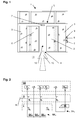
In der Fig. 1 ist eine Schiebetüranlage 1 in Frontansicht dargestellt. Die Schiebetüranlage 1 weist zwei Schiebeflügel 2 auf, welche in einer ortsfest im Bereich einer Antriebseinrichtung 5 angeordneten Laufschiene verschiebbar geführt und von der Antriebseinrichtung 5 antreibbar sind. Seitlich der Schiebeflügel 2 sind zwei Festfelder 3 angeordnet, welche einen Durchgangsbereich 4 der Schiebetüranlage 1 begrenzen. Die Schiebeflügel 2 geben im geöffneten Zustand den Durchgangsbereich 4 frei, welcher zwischen einem vor der Schiebetüranlage 1 angeordneten Bereich 11 und einem hinter der Schiebetüranlage 1 angeordneten Bereich 12 liegt.In Fig. 1 a sliding door system 1 is shown in front view. The sliding door system 1 has two sliding
Die verschiedenen Betriebszustände der Schiebetüranlage 1 sind mittels eines Programmschalters 6 einstellbar, welcher in der Nähe der Schiebetüranlage 1 ortsfest angeordnet ist. Es kann vorgesehen sein, dass diese Einstellungsmöglichkeit nur für hierzu autorisierte Personen besteht, beispielsweise durch Schlüsselbetätigung oder über eine Codeeingabeeinrichtung, um unerwünschte Einste I-lungen von Betriebszuständen der Schiebetüranlage 1 zu vermeiden.The various operating states of the sliding door system 1 are adjustable by means of a
Oberhalb des Durchgangsbereichs 4 der Schiebetüranlage 1 ist mindestens ein Sensor 7 angeordnet, welcher als Bewegungsmelder ausgebildet sein kann. Der Sensor 7 erfasst einen sich vor der Schiebetüranlage 1 befindenden Erfassungsbereich, wobei auf der anderen Seite der Schiebetüranlage 1 ein weiterer Sensor angeordnet sein kann, welcher in entsprechender Weise einen sich hinter der Schiebetüranlage 1 befindenden Erfassungsbereich erfasst.Above the
Der vor der Schiebetüranlage 1 angeordnete Bereich 11 kann als potenzieller Gefahrenbereich, beispielsweise als Innenraum eines Gebäudes ausgebildet sein und der hinter der Schiebetüranlage 1 angeordnete Bereich 12 als Fluc htbereich, so dass ein Fluchtweg mit einer Fluchtrichtung 10 durch den Durchgangsbereich 4 der Schiebetüranlage 1 führen kann. Die Schiebetüranlage 1 muss hierzu so ausgebildet sein, dass die Schiebeflügel 2 nach Ansteuerung der Steuerungseinrichtung (SE) mit einem Notfallsignal und/oder bei Ausfall der Netzstromversorgung zur Freigabe des Fluchtwegs schnellstmöglich und vollständig geöffnet werden, zumindest jedoch innerhalb einer vorgegebenen Maximalzeit eine ebenfalls vorgegebene Minimalöffnungsweite, beispielsweise 80% der vollständigen Öffnungsweite.The arranged in front of the sliding door system 1
Um in bestimmten Betriebszuständen eine sichere Verriegelung der Schiebetüranlage 1 zu erreichen, beispielsweise für den Fall, dass die Schiebetüranlage 1 nicht permanent beaufsichtigt werden kann, ist es vorgesehen, dass die Schiebeflügel 2 der Schiebetüranlage 1 über eine (in der Fig. 1 nicht dargestellte) Verriegelungseinrichtung VE in ihrer Geschlossenlage verriegelbar sind. Die Verriegelungseinrichtung VE kann über den Programmschalter 6 betätigbar sein, so dass sie in mindestens einem Betriebszustand der Schiebetüranlage 1 im verriegelten Zustand wirksam ist. Um bei Ausfall des elektrischen Energieversorgungsnetzes, an welches die Schiebetüranlage 1 angeschlossen ist, eine Entriegelung der Verriegelungseinrichtung VE sicherzustellen und den durch den Durchgang 4 der Schiebetüranlage 1 führenden Fluchtweg freizugeben, ist es vorgesehen, dass die Verriegelungseinrichtung VE mit dem Arbeitsstromprinzip betreibbar ist, d.h. dass sich die Verriegelungseinrichtung VE bei Bestromung in ihrer verriegelnden Stellung befindet und bei fehlender Bestromung selbsttätig in ihre entriegelnde Stellung gelangt. Die mit dem Arbeitsstromprinzip betreibbare Verriegelungseinrichtung VE kann als elektrischen Aktor einen Elektromagneten oder einen Elektromotor aufweisen, welcher bei Bestromung das Verriegelungselement der Verriegelungseinrichtung VE, beispielsweise einen Verriegelungsbolzen, in seine verriegelnde Stellung beaufschlagt. Ferner kann die mit dem Arbeitsstromprinzip betreibbare Verriegelungseinrichtung VE eine Rückführeinrichtung für das Verriegelungselement aufweisen, welche bei fehlender Bestromung des elektrischen Aktors das Verriegelungselement in seine entriegelnde Stellung beaufschlagt und beispielsweise als mechanischer Energiespeicher ausgebildet sein kann.In order to achieve a secure locking of the sliding door system 1 in certain operating states, for example, in the event that the sliding door system 1 can not be permanently supervised, it is provided that the sliding
In der Nähe der Schiebetüranlage 1, in diesem Ausführungsbeispiel an einem neben dem Festfeld 3 angeordneten Pfosten, ist eine Freischalteinrichtung 8 angeordnet, mittels welcher die Verriegelungseinrichtung VE entriegelbar ist. Zusätzlich kann die Freischalteinrichtung 8 auch eine Öffnung der Schiebeflügel 2 durch die Antriebseinrichtung 5 bewirken. Die Freischalteinrichtung 8 weist eine manuell betätigbare Betätigungseinrichtung 9 auf, welche beispielsweise als Nottaster ausgebildet ist. Die Betätigung der Freischalteinrichtung 8 ist auf verschiedene Arten anzeigbar: Zum Einen durch optische und/oder akustische Signalgeber im Bereich der Schiebetüranlage 1 und/oder zum Anderen an von der Schiebetüranlage 1 entfernter Stelle über einen Signalausgang, welcher in der Freischalteinrichtung 8 oder an anderer Stelle der Schiebetüranlage 1 angeordnet und beispielsweise als Schnittstelle für ein Bussystem ausgebildet ist. Über den Signalausgang kann also ein die Betätigung der Freischalteinrichtung 8 anzeigendes Signal an eine zentrale Überwachungseinrichtung ausgegeben werden.In the vicinity of the sliding door system 1, in this embodiment, on a post arranged adjacent to the fixed
In der Fig. 2 ist ein erstes Ausführungsbeispiel des Freigebeschaltkreises der erfindungsgemäßen Schiebetüranlage 1 schematisch dargestellt. Die Steuerungseinrichtung SE weist einen elektrischen Anschluss auf, welcher gegenüber einem schaltbaren Ausgang ASKV, welcher beispielsweise auf Massepotenzial liegen kann, eine Versorgungsspannung U2 führt. An diese beiden Anschlüsse ist ein Verriegelungsstromkreis SKV aufgeschaltet, in welchem der elektrische Aktor der Verriegelungseinrichtung VE liegt. Bei geschlossenem Verriegelungsstromkreis SKV liegt an dem elektrischen Aktor der Verriegelungseinrichtung VE somit die Versorgungsspannung U2 an, wodurch der Aktor das Verriegelungselement der Verriegelungseinrichtung VE in seiner verriegelnde Stellung beaufschlagt. Durch Umschaltung des schaltbaren Ausgangs ASKV, beispielsweise Abtrennung vom Massepotenzial, führt durch die dann nicht mehr vorliegende Bestromung des elektrischen Aktors der Verriegelungseinrichtung VE zu einem Auslösen der Verriegelungseinrichtung VE. Die Umschaltung des schaltbaren Ausgangs ASKV kann beispielsweise durch Betätigung des Programmschalters 6 oder durch einen Programmablauf der Steuerungseinrichtung SE ausgelöst werden. 2 , a first embodiment of the release circuit of the sliding door system 1 according to the invention is shown schematically. The control device SE has an electrical connection, which leads to a switchable output A SKV , which can be at ground potential, for example, a supply voltage U 2 . At these two terminals, a locking circuit SK V is switched , in which the electrical actuator of the locking device VE is located. When the interlock circuit SK V is closed, the electric actuator of the locking device VE is thus the one Supply voltage U 2 , whereby the actuator acts on the locking element of the locking device VE in its locking position. By switching the switchable output A SKV , for example, separation from the ground potential, leads by the then no longer present energization of the electrical actuator of the locking device VE to trigger the locking device VE. The switching of the switchable output A SKV can be triggered, for example, by pressing the
Zur Unterbrechung der Bestromung der Verriegelungseinrichtung VE ist in dem Verriegelungsstromkreis SKV außerdem ein als Öffner ausgebildeter Schaltkontakt S3 angeordnet, welcher über die Betätigungseinrichtung 9 der Freischalteinrichtung 8 betätigbar ist.To interrupt the energization of the locking device VE is in the locking circuit SK V also designed as an opener switching contact S 3 is arranged, which is actuated via the
Der beispielsweise als Bewegungsmelder ausgebildete Sensor 7 ist in diesem Ausführungsbeispiel nur schematisch dargestellt, da hier lediglich seine Funktion im Ansteuerspannungsstromkreis SKA dargestellt werden soll. Über den Anste u-erspannungsstromkreis SKA ist eine Ansteuerspannung U1 über mehrere Teilstromkreise SKA1, SKA2, SKA3 auf mehrere Eingänge E1, E2, E3 der Steuerungseinrichtung SE aufschaltbar. Der Sensor 7 weist einen in dem Teilstromkreis SKA1 angeordneten, als Öffner ausgebildeten Schaltkontakt S4 auf, welcher bei Ansteuerung des Sensors 7 öffnet und somit den Teilstromkreis SKA1 unterbricht. Beim hierdurch bewirkten Abschalten der Ansteuerspannung U1 von dem der Ansteuerung der Antriebseinrichtung 5 dienenden Eingang E1 wird durch die Steuerungseinrichtung SE eine Öffnung der Schiebeflügel 2 durch die Antriebseinrichtung 5 ausgelöst. Bei Schließen des Schaltkontakts S4, d.h. bei fehlender Anste u-erung des Sensors 7 und somit wiederkehrender Ansteuerspannung U1 am Eingang E1 wird durch die Steuerungseinrichtung SE, gegebenenfalls nach Ablauf einer vorbestimmten, in der Steuerungseinrichtung SE hinterlegbaren Offenhaltezeit, eine Schließung der Schiebeflügel 2 durch die Antriebseinrichtung 5 bewirkt.The example designed as a
Außerdem sind über die Betätigungseinrichtung 9 der Freischalteinrichtung 8, gemeinsam mit dem vorangehend beschriebenen Schaltkontakt S3, zwei weitere, jeweils als Öffner ausgebildete Schaltkontakte S1, S2 betätigbar, welche in dem Ansteuerspannungsstromkreis SKA angeordnet sind. Die über die Betätigungseinrichtung 9 der Freischalteinrichtung 8 bewirkte Öffnung des Schaltkontakts S1 der Freischalteinrichtung 8, welcher in Reihe mit dem Schaltkontakt S4 des Sensors ebenfalls in dem Teilstromkreis SKA1 liegt, bewirkt also ebenfalls die Auslösung einer Öffnung der Schiebeflügel 2 durch die Antriebseinrichtung 5.In addition, via the
Die freien Eingänge E2, E3 der Steuerungseinrichtung dienen der Fehlersicherheit, konkret der Überprüfung des Sensors 7, der Freischalteinrichtung 8 sowie der dazugehörigen Verkabelung:The free inputs E 2 , E 3 of the control device are used for error safety, specifically the verification of the
Bei Ansteuerung des Sensors 7 wird - neben dem bereits beschriebenen Schaltkontakt S4 im Teilstromkreis SKA1 - auch der in dem weiteren Teilstromkreis SKA3 befindliche, als Öffner ausgebildete Schaltkontakt S5 des Sensors 7 geöffnet und somit die Ansteuerspannung U1 von dem Eingang E3 der Steuerungseinrichtung SE abgeschaltet. Die an den Eingängen E1, E3 anliegenden Signale (Spannungen) werden miteinander verglichen. Eine Abweichung der an den Eingängen E1, E3 anliegenden Signale voneinander bedeutet eine Störung, beispielsweise eines der Schaltkontakt S4, S5 des Sensors 7. Die Steuerungseinrichtung SE kann dann mit einer Sicherheitsreaktion, beispielsweise mit einer Notöffnung der Schiebeflügel 2 und gegebenenfalls mit einer Anzeige der Störung, auf diese Störung reagieren.When driving the sensor 7 - in addition to the already described switching contact S 4 in the subcircuit SK A1 - also located in the other subcircuit SK A3 , designed as a normally closed switch contact S5 of the
Bei Betätigung der Betätigungseinrichtung 9 der Freischalteinrichtung 8 wirdneben dem bereits beschriebenen Schaltkontakt S1 im Teilstromkreis SKA1 - auch der in dem weiteren Teilstromkreis SKA2 befindliche Schaltkontakt S2 geöffnet und somit die Ansteuerspannung U1 von dem Eingang E2 der Steuerungseinrichtung SE abgeschaltet. Auch die an den Eingängen E1, E2 anliegenden Signale (Spannungen) werden miteinander verglichen. Eine Abweichung der an den Eingängen E1, E2 anliegenden Signale voneinander bedeutet eine Störung, beispielsweise eines der Schaltkontakte S1, S2. Die Steuerungseinrichtung SE kann dann mit einer Sicherheitsreaktion auch auf diese Störung reagieren.Upon actuation of the
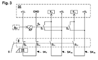
In der Fig. 3 ist ein weiteres Ausführungsbeispiel des Freigebeschaltkreises der erfindungsgemäßen Schiebetüranlage 1 schematisch dargestellt. Die Steuerungseinrichtung SE weist einen elektrischen Anschluss auf, welcher gegenüber einem Anschluss mit Massepotenzial GND eine Versorgungsspannung U3 führt. An diese beiden Anschlüsse ist ein Verriegelungsstromkreis SKV aufgeschaltet, in welchem der elektrische Aktor der Verriegelungseinrichtung VE liegt. Bei geschlossenem Verriegelungsstromkreis SKV liegt an dem elektrischen Aktor der Verriegelungseinrichtung VE somit die Versorgungsspannung U3 an, wodurch der Aktor das Verriegelungselement der Verriegelungseinrichtung VE in seiner verriegelnde Stellung beaufschlagt. Zur mehrpoligen Unterbrechung der Bestromung der Verriegelungseinrichtung VE sind in dem Verriegelungsstromkreis SKV zwei als Öffner ausgebildete Schaltkontakte S9, S10 angeordnet, welche gemeinsam über die Betätigungseinrichtung 9 der Freischalteinrichtung 8 betätigbar sind. Die mehrpolige Unterbrechung des Verriegelungsstromkreises SKV dient zur Gewährleistung der Einfehlersicherheit, da bei einem angenommenen Defekt (Nicht-Öffnen) eines der Schaltkontakte S9, S10 eine Unterbrechung des Verriegelungsstromkreises SKV durch den anderen Schaltkontakt S10, S9 erfolgt. 3 , a further embodiment of the release circuit of the sliding door system 1 according to the invention is shown schematically. The control device SE has an electrical connection, which leads to a connection to ground potential GND a supply voltage U 3 . At these two terminals, a locking circuit SK V is switched , in which the electrical actuator of the locking device VE is located. When the locking circuit SK V is closed, the supply voltage U 3 is applied to the electrical actuator of the locking device VE, as a result of which the actuator acts on the locking element of the locking device VE in its locking position. For multi-pole interruption of the energization of the locking device VE two formed as normally closed contacts S 9 , S 10 are arranged in the locking circuit SK V , which are actuated together via the
Außerdem sind über die Betätigungseinrichtung 9 der Freischalteinrichtung 8, gemeinsam mit den vorangehend beschriebenen Schaltkontakten S9, S10, zwei weitere, jeweils als Schließer ausgebildete Schaltkontakte S11, S12 betätigbar, welche jeweils in einem Ansteuerspannungsstromkreis SKA4, SKA5 angeordnet sind. Über den Ansteuerspannungsstromkreis SKA4 wird eine Ansteuerspannung U4 auf einen Eingang E4 der Steuerungseinrichtung SE aufgeschaltet, d.h. beim Anliegen der Ansteuerspannung U4 am Eingang E4 wird durch die Steuerungseinrichtung SE eine Öffnung der Schiebeflügel 2 durch die Antriebseinrichtung 5 ausgelöst. Entsprechendes gilt für den Eingang E5 der Steuerungseinrichtung SE, an welchen über den Ansteuerspannungsstromkreis SKA5 eine Ansteuerspannung U5 aufschaltbar ist, um über die Steuerungseinrichtung SE eine Öffnung der Schiebeflügel 2 durch die Antriebseinrichtung 5 auszulösen. Die Ansteuerspannung U4, U5 können gleich sein, jedoch vorteilhafterweise aus verschiedenen Spannungsquellen kommen, damit beim Ausfall einer Spannungsquelle immer noch eine Ansteuerung der Steuerungseinrichtung aus der anderen Spannungsquelle möglich ist. Die Betätigung der Freischalteinrichtung 8 führt zu einem Schließen der Schaltkontakte S11, S12 und somit zum Anlegen der Ansteuerspannungen U4, U5 an die Eingänge E4, E5 der Steuerungseinrichtung SE. Das mehrfache Vorhandensein der Eingänge E4, E5 sowie das Aufschalten der Ansteuerspannungen U4, U5 über mehrere Schaltkontakte S11, S12 dient zur Gewährleistung der Einfehlersicherheit, da beim Defekt (Nicht-Schließen) eines der Schaltkontakte S11, S12 ein Aufschalten einer Ansteuerspannung U5, U4 über den anderen Schaltkontakt S12, S11 erfolgt.In addition, via the
Die Betätigung der Freischalteinrichtung 8 führt somit zum Entriegeln der Verriegelungseinrichtung VE sowie zum über die Steuerungseinrichtung SE ausgelösten Öffnen der Schiebeflügel 2 durch die Antriebseinrichtung 5. Die Freischalteinrichtung 8 ist für Notsituationen vorgesehen, in welchen der Durchgangsbereich 4 der Schiebetüranlage 1 als Fluchtweg genutzt wird, d.h. nach Betätigung der Freischalteinrichtung 8 verbleiben die Schiebeflügel 2 nach ihrer Öffnung solange im geöffneten Zustand, bis eine autorisierte Person die Freischalteinrichtung 8 zurücksetzt. Hierfür kann die Betätigungseinrichtung 9 der Freischalteinrichtung 8 eine Schutzeinrichtung, z.B. plombierte Abdeckung aufweisen, die zwar ein Betätigen, nicht jedoch ein Zurücksetzen der Betätigungseinrichtung 9 erlaubt.The activation of the
Um jedoch auch eine vorübergehende Öffnungsmöglichkeit der verriegelten Schiebetüranlage 1, d.h. mit anschließender Schließung und Verriegelung der Schiebeflügel 2 zu ermöglichen, ist neben der Freischalteinrichtung 8 zusätzlich eine Kurzzeitfreigabeeinrichtung vorgesehen. Diese weist ein Freigaberelais KF auf, welches durch ein Auslösesignal AKF ansteuerbar ist. Das Auslösesignal AKF kann von einer (nicht dargestellten) Schaltereinrichtung abgegeben werden, welche als Schlüsseltaster, Codeeingabevorrichtung oder dergleichen ausgebildet sein kann. Das Freigaberelais KF kann als Zeitrelais ausgebildet sein, d.h. nach seiner Ansteuerung verbleibt das Relais für eine vorbestimmte Zeit in dem durch die Ansteuerung ausgelösten Schaltzustand und schaltet nach Ablauf dieser Zeit selbsttätig wieder in seinen ursprünglichen Schaltzustand um.However, in order to allow a temporary opening possibility of the locked sliding door system 1, ie with subsequent closure and locking of the sliding
In dem Verriegelungsstromkreis SKV ist ein als Öffner ausgebildeter, durch das Freigaberelais KF betätigbarer Schaltkontakt S6 angeordnet, welcher bei Ansteuerung des Freigaberelais KF den Verriegelungsstromkreis SKV unterbricht und somit eine Aufhebung der Bestromung der Verriegelungseinrichtung VE bewirkt. Ferner sind durch das Freigaberelais KF zwei jeweils in den Ansteuerspannungsstromkreisen SKA4, SKA5 angeordnete, als Schließer ausgebildete Schaltkontakte S7, S8 betätigbar, welche bei Ansteuerung des Freigaberelais KF die Ansteuerspannungsstromkreise SKA4, SKA5 jeweils schließen und somit über die Steuerungseinrichtung SE eine Öffnung der Schiebeflügel 2 durch die Antriebseinrichtung 5 auslösen. Nach Ablauf der Ansteuerung des Freigaberelais KF gelangen die Schaltkontakte S6, S7, S8 in ihre Ausgangsposition. Hierdurch werden die A n-steuerspannungsstromkreise SKA4, SKA5 unterbrochen, was, gegebenenfalls nach Ablauf einer vorbestimmten, in der Steuerungseinrichtung SE hinterlegbaren Offenhaltezeit, eine Schließung der Schiebeflügel 2 durch die Antriebseinrichtung 5 bewirkt. Ferner wird der Verriegelungsstromkreis SKV geschlossen, wodurch die Schiebeflügel 2 nach Erreichen ihrer Geschlossenlage wieder verriegelbar sind.In the locking circuit SK V designed as an opener, actuated by the release relay KF switching contact S 6 is arranged, which interrupts the locking circuit SK V when driving the release relay KF and thus causes a cancellation of the energization of the locking device VE. Furthermore, by the release relay KF two each arranged in the Ansteuerspannungsstromkreisen SK A4 , SK A5 , designed as normally open switch contacts S 7 , S 8 can be actuated, which close when driving the release relay KF the Ansteuerspannungsstromkreise SK A4 , SK A5 and thus via the control device SE an opening of the sliding
- 11
- Schiebetüranlagesliding door system
- 22
- Schiebeflügelsliding panel
- 33
- Festfeldfixed panel
- 44
- DurchgangsbereichPassage area
- 55
- Antriebseinrichtungdriving means
- 66
- Programmschalterprogram switch
- 77
- Sensorsensor
- 88th
- FreischalteinrichtungDisconnection device
- 99
- Betätigungseinrichtungactuator
- 1010
- Fluchtrichtungescape direction
- 1111
- BereichArea
- 1212
- BereichArea
- AKF A KF
- Auslösesignaltrigger signal
- E1 E 1
- Eingangentrance
- E2 E 2
- Eingangentrance
- E3 E 3
- Eingangentrance
- E4 E 4
- Eingangentrance
- E5 E 5
- Eingangentrance
- GNDGND
- Massepotenzialground potential
- KFKF
- Freigaberelaisrelease relay
- SESE
- Steuerungseinrichtungcontrol device
- SKV SK V
- VerriegelungsstromkreisLocking circuit
- SKA SK A
- AnsteuerspannungsstromkreisAnsteuerspannungsstromkreis
- SKA1 SK A1
- TeilstromkreisPart Circuit
- SKA2 SK A2
- TeilstromkreisPart Circuit
- SKA3 SK A3
- TeilstromkreisPart Circuit
- SKA4 SK A4
- AnsteuerspannungsstromkreisAnsteuerspannungsstromkreis
- SKA5 SK A5
- AnsteuerspannungsstromkreisAnsteuerspannungsstromkreis
- S1 S 1
- Schaltkontaktswitching contact
- S2 S 2
- Schaltkontaktswitching contact
- S3 S 3
- Schaltkontaktswitching contact
- S4 S 4
- Schaltkontaktswitching contact
- S5 S 5
- Schaltkontaktswitching contact
- S6 S 6
- Schaltkontaktswitching contact
- S7 S 7
- Schaltkontaktswitching contact
- S8 S 8
- Schaltkontaktswitching contact
- S9 S 9
- Schaltkontaktswitching contact
- S10 S 10
- Schaltkontaktswitching contact
- S11 P 11
- Schaltkontaktswitching contact
- S12 S 12
- Schaltkontaktswitching contact
- U1 U 1
- Ansteuerspannungdriving voltage
- U2 U 2
- Versorgungsspannungsupply voltage
- U3 U 3
- Versorgungsspannungsupply voltage
- U4 U 4
- Ansteuerspannungdriving voltage
- U5 U 5
- Ansteuerspannungdriving voltage
- VEVE
- Verriegelungseinrichtunglocking device
Claims (14)
wobei die Schiebetüranlage (1) in einem Flucht- und Rettungsweg einsetzbar ist, indem die Antriebseinrichtung (5) so ausgebildet ist, dass der Schiebeflügel (2) beim Vorliegen eines Notfallsignals zur Freigabe eines Fluchtwegs geöffnet wird, und
wobei die Schiebetüranlage (1) in zumindest einem Betriebszustand durch eine Verriegelungseinrichtung (VE) verriegelbar ist,
dadurch gekennzeichnet,
dass eine Freischalteinrichtung (8) zur Entriegelung der Verriegelungseinrichtung (VE) und zur Öffnung des Schiebeflügels (2) vorhanden ist.Sliding door system (1) with at least one sliding leaf (2) which can be driven by means of an A n-drive device (5) controlled by an electronic control device,
wherein the sliding door system (1) can be used in an escape and rescue route by the drive device (5) is designed so that the sliding sash (2) is opened in the presence of an emergency signal to release an escape route, and
wherein the sliding door system (1) can be locked in at least one operating state by a locking device (VE),
characterized,
is present that an isolating means (8) for unlocking the locking device (VE) and to the opening of the sliding leaf (2).
dadurch gekennzeichnet, dass die Freischalteinrichtung (8) redundant ausgebildet ist, indem mindestens ein Bauteil der Freischaltei nrichtung (8) mindestens zweifach vorhanden ist, so dass bei Ausfall eines dieser Bauteile dessen Funktion von einem anderen, gleichartigen Bauteil übernommen wird.Sliding door system according to claim 1,
characterized in that the enabling device (8) is designed to be redundant by at least one component of the Freischaltei device (8) is present at least twice, so that in case of failure of one of these components whose function is taken over by another, similar component.
dadurch gekennzeichnet, dass die Freischalteinrichtung (8) einfehlersicher ausgebildet ist, so dass die Funktion der Freischalteinrichtung (8) auch bei einer Störung eines Bauteils noch gewährleistet ist.Sliding door system according to claim 1,
characterized in that the disconnecting device (8) is designed so that it is safe against error, so that the function of the disconnecting device (8) is still ensured even in the case of a malfunction of a component.
dadurch gekennzeichnet, dass die Freischalteinrichtung (8) selbstüberwachend ausgebildet ist, indem eine Überwachungseinrichtung vorgesehen ist, welche die Funktionsfähigkeit der Freischalteinrichtung (8) überwacht.Sliding door system according to claim 1,
characterized in that the enabling device (8) is self-monitoring formed by a monitoring device is provided which monitors the operability of the enabling device (8).
dadurch gekennzeichnet, dass die Steuerungseinrichtung (SE) selbstüberwachend ausgebildet ist, indem eine Überwachungseinrichtung vorgesehen ist, welche die Funktionsfähigkeit der Steuerungseinrichtung (SE) überwacht.Sliding door system according to claim 1,
characterized in that the control device (SE) is self-monitoring formed by a monitoring device is provided which monitors the functioning of the control device (SE).
dadurch gekennzeichnet, dass die Freischalteinrichtung (8) eine elektrisch ansteuerbare Betätigungseinrichtung (9) aufweist.Sliding door system according to claim 1,
characterized in that the disconnecting device (8) has an electrically controllable actuating device (9).
dadurch gekennzeichnet, dass die Betätigungseinrichtung (9) mindestens einen Eingang für ein Notfallsignal aufweist.Sliding door system according to claim 6,
characterized in that the actuating device (9) has at least one input for an emergency signal.
dadurch gekennzeichnet, dass die Freischalteinrichtung (8) eine manuell betätigbare Betätigungseinrichtung (9) aufweist.Sliding door system according to claim 1,
characterized in that the unlocking device (8) has a manually operable actuating device (9).
dadurch gekennzeichnet, dass die Verriegelungseinrichtung (VE) nach dem Arbeitsstromprinzip betreibbar ist, d.h. das die Verriegelungseinrichtung (VE) durch Bestromung in den verriegelten Zustand überführbar ist.Sliding door system according to claim 1,
characterized in that the locking device (VE) according to the working current principle is operable, that is, the locking device (VE) can be converted by energization in the locked state.
dadurch gekennzeichnet, dass die Verriegelungseinrichtung (VE) in einem Verriegelungsstromkreis (SKV) angeordnet ist, an welchem eine Versorgungsspannung (U2, U3) anliegt, wobei der Verriegelungsstromkreis (SKV) durch die Freischalteinrichtung (8) unterbrechbar ist.Sliding door system according to claim 1,
characterized in that the locking device (VE) is arranged in a locking circuit (SK V ) to which a supply voltage (U 2 , U 3 ) is applied, wherein the locking circuit (SK V ) by the enabling device (8) can be interrupted.
dadurch gekennzeichnet, dass die Steuerungseinrichtung (SE) mindestens einen Eingang (E1, E4, E5) für mindestens eine Ansteue r-spannung (U1, U4, U5) aufweist, wobei die Ansteuerspannung (U1, U4, U5) über mindestens einen Ansteuerspannungsstromkreis (SKA, SKA4, SKA5) auf den Eingang (E1, E4, E5) aufschaltbar ist.Sliding door system according to claim 1,
characterized in that the control device (SE) has at least one input (E 1 , E 4 , E 5 ) for at least one r-voltage ruling (U 1 , U 4 , U 5 ), wherein the drive voltage (U 1 , U 4 , U 5 ) via at least one Ansteuerspannungsstromkreis (SK A , SK A4 , SK A5 ) on the input (E 1 , E 4 , E 5 ) can be connected.
dadurch gekennzeichnet, dass die Freischalteinrichtung (8) mindestens eine optische und/oder akustische Anzeigeeinrichtung zur A n-zeige der Betätigung der Freischalteinrichtung (8) aufweist.Sliding door system according to claim 1,
characterized in that the enabling device (8) has at least one optical and / or acoustic display device for displaying the operation of the disconnecting device (8).
dadurch gekennzeichnet, dass die Freischalteinrichtung (8) mindestens einen Signalausgang zur Ausgabe eines die Betätigung der Freischalteinrichtung (8) anzeigenden Signals aufweist.Sliding door system according to claim 1,
characterized in that the disconnecting device (8) has at least one signal output for outputting a signal indicating the actuation of the disconnecting device (8).
dadurch gekennzeichnet, dass ein durch ein Auslösesignal (AKF) ansteuerbares Freigaberelais (KF) vorhanden ist, mit welchem eine vorübergehende Freischaltung der Verriegelungseinrichtung (VE) sowie eine vorübergehende Ansteuerung mindestens eines der Eingänge (E4, E5) bewirkbar ist.Sliding door system according to claim 1,
characterized in that an activatable by a trigger signal (A KF ) release relay (KF) is present, with which a temporary release of the locking device (VE) and a temporary control of at least one of the inputs (E 4 , E 5 ) is effected.
Priority Applications (1)
| Application Number | Priority Date | Filing Date | Title |
|---|---|---|---|
| PL07107049.4T PL1849951T5 (en) | 2006-04-28 | 2007-04-26 | Sliding door assembly |
Applications Claiming Priority (1)
| Application Number | Priority Date | Filing Date | Title |
|---|---|---|---|
| DE102006020372A DE102006020372B4 (en) | 2006-04-28 | 2006-04-28 | sliding door system |
Publications (4)
| Publication Number | Publication Date |
|---|---|
| EP1849951A2 true EP1849951A2 (en) | 2007-10-31 |
| EP1849951A3 EP1849951A3 (en) | 2012-10-10 |
| EP1849951B1 EP1849951B1 (en) | 2015-03-11 |
| EP1849951B2 EP1849951B2 (en) | 2020-02-19 |
Family
ID=38171580
Family Applications (1)
| Application Number | Title | Priority Date | Filing Date |
|---|---|---|---|
| EP07107049.4A Active EP1849951B2 (en) | 2006-04-28 | 2007-04-26 | Sliding door assembly |
Country Status (4)
| Country | Link |
|---|---|
| EP (1) | EP1849951B2 (en) |
| DE (1) | DE102006020372B4 (en) |
| ES (1) | ES2532844T5 (en) |
| PL (1) | PL1849951T5 (en) |
Cited By (2)
| Publication number | Priority date | Publication date | Assignee | Title |
|---|---|---|---|---|
| EP2267261A3 (en) * | 2009-06-26 | 2014-05-07 | GEZE GmbH | Automatic door system |
| EP3067504B1 (en) | 2015-03-13 | 2019-05-08 | GU Automatic GmbH | Automatic door, such as a sliding door, a revolving door or the like |
Families Citing this family (4)
| Publication number | Priority date | Publication date | Assignee | Title |
|---|---|---|---|---|
| DE202009005032U1 (en) * | 2009-07-16 | 2010-09-23 | Gu Automatic Gmbh | Automatic escape route sliding door with at least one movable door leaf |
| DE102010002870B4 (en) * | 2010-03-15 | 2013-08-29 | Geze Gmbh | Sliding door system and method for operating a sliding door system |
| DE102015113228A1 (en) | 2015-08-11 | 2017-02-16 | Gu Automatic Gmbh | Automatic door, such as a sliding door, a revolving door or the like |
| DE102019209103A1 (en) * | 2019-06-24 | 2020-12-24 | Geze Gmbh | Device for opening and / or closing a component |
Citations (5)
| Publication number | Priority date | Publication date | Assignee | Title |
|---|---|---|---|---|
| GB1368218A (en) | 1972-06-14 | 1974-09-25 | Ver Baubeschlag Gretsch Co | Hydraulically-damped sliding doors with electro- mechanical driving means |
| AU570637B2 (en) | 1982-06-22 | 1988-03-24 | Secton Pty. Ltd. | Sliding door closer |
| DE3940762A1 (en) | 1989-12-09 | 1991-06-13 | Hein Gmbh Christian | SLIDING DOOR |
| DE4028190A1 (en) | 1990-09-05 | 1992-03-12 | Dorma Gmbh & Co Kg | Automatic door control system - uses back=up energy storage unit that is monitored to provide safe operation of doors |
| DE4344729A1 (en) | 1993-12-27 | 1995-06-29 | Siemens Ag | Control and / or regulation of a door |
Family Cites Families (8)
| Publication number | Priority date | Publication date | Assignee | Title |
|---|---|---|---|---|
| DE19507407B4 (en) | 1994-03-04 | 2006-03-02 | Geze Gmbh | Device for operating and monitoring smoke and heat exhaust openings |
| DE19531323A1 (en) | 1994-10-15 | 1996-04-18 | Geze Gmbh & Co | Diagnosing and/or monitoring of safety unit for door or window system |
| PT1065577E (en) | 1999-06-27 | 2004-08-31 | Geze Gmbh | SECURITY DEVICE FOR AT LEAST ONE DOOR OF PREFERENCE INSTALLED IN EMERGENCY OUTPUTS |
| DE10011763A1 (en) | 1999-06-27 | 2000-12-28 | Geze Gmbh | Locking device for door(s), preferably in escape and rescue routes, has local and central emergency off switches for lock arrangement with separate electrical circuits |
| DE19949453B4 (en) | 1999-09-06 | 2013-08-29 | Geze Gmbh | Automatic door or window system |
| DE19949744B4 (en) * | 1999-10-15 | 2014-05-22 | Geze Gmbh | Drive device for a door |
| DE10025082A1 (en) * | 2000-05-20 | 2001-12-06 | Geze Gmbh | Security and monitoring device |
| DE102004023927C5 (en) * | 2004-05-12 | 2010-05-06 | Dorma Gmbh + Co. Kg | Sliding door system with a drive device arranged in a fighter |
-
2006
- 2006-04-28 DE DE102006020372A patent/DE102006020372B4/en not_active Revoked
-
2007
- 2007-04-26 ES ES07107049T patent/ES2532844T5/en active Active
- 2007-04-26 EP EP07107049.4A patent/EP1849951B2/en active Active
- 2007-04-26 PL PL07107049.4T patent/PL1849951T5/en unknown
Patent Citations (5)
| Publication number | Priority date | Publication date | Assignee | Title |
|---|---|---|---|---|
| GB1368218A (en) | 1972-06-14 | 1974-09-25 | Ver Baubeschlag Gretsch Co | Hydraulically-damped sliding doors with electro- mechanical driving means |
| AU570637B2 (en) | 1982-06-22 | 1988-03-24 | Secton Pty. Ltd. | Sliding door closer |
| DE3940762A1 (en) | 1989-12-09 | 1991-06-13 | Hein Gmbh Christian | SLIDING DOOR |
| DE4028190A1 (en) | 1990-09-05 | 1992-03-12 | Dorma Gmbh & Co Kg | Automatic door control system - uses back=up energy storage unit that is monitored to provide safe operation of doors |
| DE4344729A1 (en) | 1993-12-27 | 1995-06-29 | Siemens Ag | Control and / or regulation of a door |
Cited By (2)
| Publication number | Priority date | Publication date | Assignee | Title |
|---|---|---|---|---|
| EP2267261A3 (en) * | 2009-06-26 | 2014-05-07 | GEZE GmbH | Automatic door system |
| EP3067504B1 (en) | 2015-03-13 | 2019-05-08 | GU Automatic GmbH | Automatic door, such as a sliding door, a revolving door or the like |
Also Published As
| Publication number | Publication date |
|---|---|
| DE102006020372A1 (en) | 2007-10-31 |
| ES2532844T3 (en) | 2015-04-01 |
| ES2532844T5 (en) | 2020-12-17 |
| EP1849951A3 (en) | 2012-10-10 |
| DE102006020372B4 (en) | 2009-12-24 |
| EP1849951B1 (en) | 2015-03-11 |
| PL1849951T5 (en) | 2023-05-22 |
| EP1849951B2 (en) | 2020-02-19 |
| PL1849951T3 (en) | 2015-08-31 |
Similar Documents
| Publication | Publication Date | Title |
|---|---|---|
| EP1849951B1 (en) | Sliding door assembly | |
| EP3067504B1 (en) | Automatic door, such as a sliding door, a revolving door or the like | |
| WO2010060534A1 (en) | Safety switch for creating a system release signal in dependence on the position of a movable guard door | |
| EP0947658B1 (en) | Drive for a door | |
| EP3418482B1 (en) | Electric door drive, security door and method of operating a security door | |
| EP2400104A2 (en) | Fire-retardant sliding door and method for operating same | |
| DE102019002873A1 (en) | Locking device for a vehicle door of a motor vehicle | |
| EP2725172A2 (en) | Method for operating a rescue path device and rescue path assembly | |
| DE4033840A1 (en) | Emergency exit door opening system - uses release spring acting on toggle lever mechanism for opening each locking element under electric control | |
| EP3258045B1 (en) | Door drive | |
| EP1065577A2 (en) | Safety device for at least one door, preferably for escape routes | |
| DE19929193A1 (en) | Escape and rescue route device has magnetic and/or electromechanical locking device, local and/or central controller(s), service terminal with wireless data interface communications device | |
| EP3792437A1 (en) | Method for power-assisted movement of a door and door actuator | |
| EP3130736A1 (en) | Automatic door, such as a sliding door, a revolving door or the like | |
| EP0856629A1 (en) | Device for protecting a vehicle | |
| DE10011763A1 (en) | Locking device for door(s), preferably in escape and rescue routes, has local and central emergency off switches for lock arrangement with separate electrical circuits | |
| DE9311377U1 (en) | DEVICE FOR OPERATING A RELEASE RELEASE FOR DOOR CLOSINGS | |
| EP1849950B1 (en) | Sliding door system | |
| DE102009008537B3 (en) | pushbutton | |
| EP3859111B1 (en) | Fixing system for a fire or smoke protection door and arrangement with such a system | |
| DE102004025097A1 (en) | Door outer handle for a vehicle comprises a region with sensor surfaces for opening and closing the door | |
| EP3557114B1 (en) | Safety switch | |
| DE820874C (en) | Circuit arrangement for electrical room protection systems | |
| DE19722927C1 (en) | Switching device with in-built safety function for protecting personnel from injury due to moving machinery or plant | |
| DE102014001864B3 (en) | Lock for a vehicle door |
Legal Events
| Date | Code | Title | Description |
|---|---|---|---|
| PUAI | Public reference made under article 153(3) epc to a published international application that has entered the european phase |
Free format text: ORIGINAL CODE: 0009012 |
|
| AK | Designated contracting states |
Kind code of ref document: A2 Designated state(s): AT BE BG CH CY CZ DE DK EE ES FI FR GB GR HU IE IS IT LI LT LU LV MC MT NL PL PT RO SE SI SK TR |
|
| AX | Request for extension of the european patent |
Extension state: AL BA HR MK YU |
|
| PUAL | Search report despatched |
Free format text: ORIGINAL CODE: 0009013 |
|
| AK | Designated contracting states |
Kind code of ref document: A3 Designated state(s): AT BE BG CH CY CZ DE DK EE ES FI FR GB GR HU IE IS IT LI LT LU LV MC MT NL PL PT RO SE SI SK TR |
|
| AX | Request for extension of the european patent |
Extension state: AL BA HR MK RS |
|
| RIC1 | Information provided on ipc code assigned before grant |
Ipc: E05F 15/20 20060101AFI20120903BHEP Ipc: E05F 15/14 20060101ALI20120903BHEP |
|
| 17P | Request for examination filed |
Effective date: 20130311 |
|
| AKX | Designation fees paid |
Designated state(s): AT BE BG CH CY CZ DE DK EE ES FI FR GB GR HU IE IS IT LI LT LU LV MC MT NL PL PT RO SE SI SK TR |
|
| GRAP | Despatch of communication of intention to grant a patent |
Free format text: ORIGINAL CODE: EPIDOSNIGR1 |
|
| INTG | Intention to grant announced |
Effective date: 20141002 |
|
| GRAS | Grant fee paid |
Free format text: ORIGINAL CODE: EPIDOSNIGR3 |
|
| REG | Reference to a national code |
Ref country code: DE Ref legal event code: R079 Ref document number: 502007013778 Country of ref document: DE Free format text: PREVIOUS MAIN CLASS: E05F0015200000 Ipc: E05F0015632000 |
|
| GRAA | (expected) grant |
Free format text: ORIGINAL CODE: 0009210 |
|
| AK | Designated contracting states |
Kind code of ref document: B1 Designated state(s): AT BE BG CH CY CZ DE DK EE ES FI FR GB GR HU IE IS IT LI LT LU LV MC MT NL PL PT RO SE SI SK TR |
|
| REG | Reference to a national code |
Ref country code: GB Ref legal event code: FG4D Free format text: NOT ENGLISH |
|
| RIC1 | Information provided on ipc code assigned before grant |
Ipc: E05F 15/632 20150101AFI20150203BHEP Ipc: E05F 15/70 20150101ALI20150203BHEP |
|
| REG | Reference to a national code |
Ref country code: CH Ref legal event code: EP |
|
| REG | Reference to a national code |
Ref country code: ES Ref legal event code: FG2A Ref document number: 2532844 Country of ref document: ES Kind code of ref document: T3 Effective date: 20150401 |
|
| REG | Reference to a national code |
Ref country code: IE Ref legal event code: FG4D Free format text: LANGUAGE OF EP DOCUMENT: GERMAN |
|
| REG | Reference to a national code |
Ref country code: AT Ref legal event code: REF Ref document number: 715464 Country of ref document: AT Kind code of ref document: T Effective date: 20150415 Ref country code: NL Ref legal event code: T3 |
|
| REG | Reference to a national code |
Ref country code: FR Ref legal event code: PLFP Year of fee payment: 9 |
|
| REG | Reference to a national code |
Ref country code: NL Ref legal event code: T3 |
|
| REG | Reference to a national code |
Ref country code: DE Ref legal event code: R096 Ref document number: 502007013778 Country of ref document: DE Effective date: 20150423 |
|
| REG | Reference to a national code |
Ref country code: NL Ref legal event code: T3 |
|
| REG | Reference to a national code |
Ref country code: SE Ref legal event code: TRGR |
|
| PG25 | Lapsed in a contracting state [announced via postgrant information from national office to epo] |
Ref country code: LT Free format text: LAPSE BECAUSE OF FAILURE TO SUBMIT A TRANSLATION OF THE DESCRIPTION OR TO PAY THE FEE WITHIN THE PRESCRIBED TIME-LIMIT Effective date: 20150311 |
|
| REG | Reference to a national code |
Ref country code: LT Ref legal event code: MG4D |
|
| PG25 | Lapsed in a contracting state [announced via postgrant information from national office to epo] |
Ref country code: GR Free format text: LAPSE BECAUSE OF FAILURE TO SUBMIT A TRANSLATION OF THE DESCRIPTION OR TO PAY THE FEE WITHIN THE PRESCRIBED TIME-LIMIT Effective date: 20150612 Ref country code: LV Free format text: LAPSE BECAUSE OF FAILURE TO SUBMIT A TRANSLATION OF THE DESCRIPTION OR TO PAY THE FEE WITHIN THE PRESCRIBED TIME-LIMIT Effective date: 20150311 |
|
| REG | Reference to a national code |
Ref country code: PL Ref legal event code: T3 |
|
| PG25 | Lapsed in a contracting state [announced via postgrant information from national office to epo] |
Ref country code: RO Free format text: LAPSE BECAUSE OF FAILURE TO SUBMIT A TRANSLATION OF THE DESCRIPTION OR TO PAY THE FEE WITHIN THE PRESCRIBED TIME-LIMIT Effective date: 20150311 Ref country code: PT Free format text: LAPSE BECAUSE OF FAILURE TO SUBMIT A TRANSLATION OF THE DESCRIPTION OR TO PAY THE FEE WITHIN THE PRESCRIBED TIME-LIMIT Effective date: 20150713 Ref country code: EE Free format text: LAPSE BECAUSE OF FAILURE TO SUBMIT A TRANSLATION OF THE DESCRIPTION OR TO PAY THE FEE WITHIN THE PRESCRIBED TIME-LIMIT Effective date: 20150311 Ref country code: CZ Free format text: LAPSE BECAUSE OF FAILURE TO SUBMIT A TRANSLATION OF THE DESCRIPTION OR TO PAY THE FEE WITHIN THE PRESCRIBED TIME-LIMIT Effective date: 20150311 Ref country code: SK Free format text: LAPSE BECAUSE OF FAILURE TO SUBMIT A TRANSLATION OF THE DESCRIPTION OR TO PAY THE FEE WITHIN THE PRESCRIBED TIME-LIMIT Effective date: 20150311 |
|
| PG25 | Lapsed in a contracting state [announced via postgrant information from national office to epo] |
Ref country code: MC Free format text: LAPSE BECAUSE OF FAILURE TO SUBMIT A TRANSLATION OF THE DESCRIPTION OR TO PAY THE FEE WITHIN THE PRESCRIBED TIME-LIMIT Effective date: 20150311 Ref country code: IS Free format text: LAPSE BECAUSE OF FAILURE TO SUBMIT A TRANSLATION OF THE DESCRIPTION OR TO PAY THE FEE WITHIN THE PRESCRIBED TIME-LIMIT Effective date: 20150711 |
|
| REG | Reference to a national code |
Ref country code: DE Ref legal event code: R026 Ref document number: 502007013778 Country of ref document: DE |
|
| PLBI | Opposition filed |
Free format text: ORIGINAL CODE: 0009260 |
|
| 26 | Opposition filed |
Opponent name: AGTATEC AG Effective date: 20151210 Opponent name: DORMA DEUTSCHLAND GMBH Effective date: 20151211 |
|
| PLAX | Notice of opposition and request to file observation + time limit sent |
Free format text: ORIGINAL CODE: EPIDOSNOBS2 |
|
| REG | Reference to a national code |
Ref country code: IE Ref legal event code: MM4A |
|
| PG25 | Lapsed in a contracting state [announced via postgrant information from national office to epo] |
Ref country code: DK Free format text: LAPSE BECAUSE OF FAILURE TO SUBMIT A TRANSLATION OF THE DESCRIPTION OR TO PAY THE FEE WITHIN THE PRESCRIBED TIME-LIMIT Effective date: 20150311 |
|
| PG25 | Lapsed in a contracting state [announced via postgrant information from national office to epo] |
Ref country code: SI Free format text: LAPSE BECAUSE OF FAILURE TO SUBMIT A TRANSLATION OF THE DESCRIPTION OR TO PAY THE FEE WITHIN THE PRESCRIBED TIME-LIMIT Effective date: 20150311 |
|
| REG | Reference to a national code |
Ref country code: FR Ref legal event code: PLFP Year of fee payment: 10 |
|
| PG25 | Lapsed in a contracting state [announced via postgrant information from national office to epo] |
Ref country code: IE Free format text: LAPSE BECAUSE OF NON-PAYMENT OF DUE FEES Effective date: 20150426 |
|
| PLBB | Reply of patent proprietor to notice(s) of opposition received |
Free format text: ORIGINAL CODE: EPIDOSNOBS3 |
|
| PG25 | Lapsed in a contracting state [announced via postgrant information from national office to epo] |
Ref country code: MT Free format text: LAPSE BECAUSE OF FAILURE TO SUBMIT A TRANSLATION OF THE DESCRIPTION OR TO PAY THE FEE WITHIN THE PRESCRIBED TIME-LIMIT Effective date: 20150311 |
|
| REG | Reference to a national code |
Ref country code: FR Ref legal event code: PLFP Year of fee payment: 11 |
|
| PG25 | Lapsed in a contracting state [announced via postgrant information from national office to epo] |
Ref country code: BG Free format text: LAPSE BECAUSE OF FAILURE TO SUBMIT A TRANSLATION OF THE DESCRIPTION OR TO PAY THE FEE WITHIN THE PRESCRIBED TIME-LIMIT Effective date: 20150311 Ref country code: HU Free format text: LAPSE BECAUSE OF FAILURE TO SUBMIT A TRANSLATION OF THE DESCRIPTION OR TO PAY THE FEE WITHIN THE PRESCRIBED TIME-LIMIT; INVALID AB INITIO Effective date: 20070426 |
|
| PG25 | Lapsed in a contracting state [announced via postgrant information from national office to epo] |
Ref country code: CY Free format text: LAPSE BECAUSE OF FAILURE TO SUBMIT A TRANSLATION OF THE DESCRIPTION OR TO PAY THE FEE WITHIN THE PRESCRIBED TIME-LIMIT Effective date: 20150311 |
|
| PG25 | Lapsed in a contracting state [announced via postgrant information from national office to epo] |
Ref country code: TR Free format text: LAPSE BECAUSE OF FAILURE TO SUBMIT A TRANSLATION OF THE DESCRIPTION OR TO PAY THE FEE WITHIN THE PRESCRIBED TIME-LIMIT Effective date: 20150311 |
|
| APBM | Appeal reference recorded |
Free format text: ORIGINAL CODE: EPIDOSNREFNO |
|
| APBP | Date of receipt of notice of appeal recorded |
Free format text: ORIGINAL CODE: EPIDOSNNOA2O |
|
| APAH | Appeal reference modified |
Free format text: ORIGINAL CODE: EPIDOSCREFNO |
|
| APBM | Appeal reference recorded |
Free format text: ORIGINAL CODE: EPIDOSNREFNO |
|
| APBP | Date of receipt of notice of appeal recorded |
Free format text: ORIGINAL CODE: EPIDOSNNOA2O |
|
| APBY | Invitation to file observations in appeal sent |
Free format text: ORIGINAL CODE: EPIDOSNOBA2O |
|
| REG | Reference to a national code |
Ref country code: FR Ref legal event code: PLFP Year of fee payment: 12 |
|
| APBQ | Date of receipt of statement of grounds of appeal recorded |
Free format text: ORIGINAL CODE: EPIDOSNNOA3O |
|
| PLAB | Opposition data, opponent's data or that of the opponent's representative modified |
Free format text: ORIGINAL CODE: 0009299OPPO |
|
| R26 | Opposition filed (corrected) |
Opponent name: AGTATEC AG Effective date: 20151210 |
|
| PGFP | Annual fee paid to national office [announced via postgrant information from national office to epo] |
Ref country code: LU Payment date: 20190418 Year of fee payment: 13 Ref country code: NL Payment date: 20190418 Year of fee payment: 13 |
|
| PGFP | Annual fee paid to national office [announced via postgrant information from national office to epo] |
Ref country code: ES Payment date: 20190521 Year of fee payment: 13 Ref country code: FI Payment date: 20190424 Year of fee payment: 13 |
|
| APBU | Appeal procedure closed |
Free format text: ORIGINAL CODE: EPIDOSNNOA9O |
|
| PGFP | Annual fee paid to national office [announced via postgrant information from national office to epo] |
Ref country code: SE Payment date: 20190611 Year of fee payment: 13 Ref country code: SE Payment date: 20190418 Year of fee payment: 13 |
|
| PUAH | Patent maintained in amended form |
Free format text: ORIGINAL CODE: 0009272 |
|
| STAA | Information on the status of an ep patent application or granted ep patent |
Free format text: STATUS: PATENT MAINTAINED AS AMENDED |
|
| REG | Reference to a national code |
Ref country code: CH Ref legal event code: AELC |
|
| 27A | Patent maintained in amended form |
Effective date: 20200219 |
|
| AK | Designated contracting states |
Kind code of ref document: B2 Designated state(s): AT BE BG CH CY CZ DE DK EE ES FI FR GB GR HU IE IS IT LI LT LU LV MC MT NL PL PT RO SE SI SK TR |
|
| REG | Reference to a national code |
Ref country code: DE Ref legal event code: R102 Ref document number: 502007013778 Country of ref document: DE |
|
| REG | Reference to a national code |
Ref country code: NL Ref legal event code: FP |
|
| REG | Reference to a national code |
Ref country code: SE Ref legal event code: RPEO |
|
| REG | Reference to a national code |
Ref country code: FI Ref legal event code: MAE |
|
| REG | Reference to a national code |
Ref country code: NL Ref legal event code: MM Effective date: 20200501 |
|
| REG | Reference to a national code |
Ref country code: ES Ref legal event code: DC2A Ref document number: 2532844 Country of ref document: ES Kind code of ref document: T5 Effective date: 20201217 |
|
| PG25 | Lapsed in a contracting state [announced via postgrant information from national office to epo] |
Ref country code: SE Free format text: LAPSE BECAUSE OF NON-PAYMENT OF DUE FEES Effective date: 20200427 Ref country code: FI Free format text: LAPSE BECAUSE OF NON-PAYMENT OF DUE FEES Effective date: 20200426 Ref country code: LU Free format text: LAPSE BECAUSE OF NON-PAYMENT OF DUE FEES Effective date: 20200426 |
|
| REG | Reference to a national code |
Ref country code: BE Ref legal event code: MM Effective date: 20200430 |
|
| PG25 | Lapsed in a contracting state [announced via postgrant information from national office to epo] |
Ref country code: BE Free format text: LAPSE BECAUSE OF NON-PAYMENT OF DUE FEES Effective date: 20200430 |
|
| PG25 | Lapsed in a contracting state [announced via postgrant information from national office to epo] |
Ref country code: NL Free format text: LAPSE BECAUSE OF NON-PAYMENT OF DUE FEES Effective date: 20200501 |
|
| REG | Reference to a national code |
Ref country code: ES Ref legal event code: FD2A Effective date: 20210906 |
|
| PG25 | Lapsed in a contracting state [announced via postgrant information from national office to epo] |
Ref country code: ES Free format text: LAPSE BECAUSE OF NON-PAYMENT OF DUE FEES Effective date: 20200427 |
|
| P01 | Opt-out of the competence of the unified patent court (upc) registered |
Effective date: 20230510 |
|
| PGFP | Annual fee paid to national office [announced via postgrant information from national office to epo] |
Ref country code: FR Payment date: 20230420 Year of fee payment: 17 |
|
| PGFP | Annual fee paid to national office [announced via postgrant information from national office to epo] |
Ref country code: PL Payment date: 20230414 Year of fee payment: 17 |
|
| PGFP | Annual fee paid to national office [announced via postgrant information from national office to epo] |
Ref country code: GB Payment date: 20230419 Year of fee payment: 17 |
|
| PGFP | Annual fee paid to national office [announced via postgrant information from national office to epo] |
Ref country code: DE Payment date: 20240430 Year of fee payment: 18 |
|
| PGFP | Annual fee paid to national office [announced via postgrant information from national office to epo] |
Ref country code: CH Payment date: 20240501 Year of fee payment: 18 |
|
| PGFP | Annual fee paid to national office [announced via postgrant information from national office to epo] |
Ref country code: AT Payment date: 20240419 Year of fee payment: 18 |
|
| PGFP | Annual fee paid to national office [announced via postgrant information from national office to epo] |
Ref country code: IT Payment date: 20240424 Year of fee payment: 18 |