EP1848968B1 - Rollenzählwerk für verbrauchszähler - Google Patents
Rollenzählwerk für verbrauchszähler Download PDFInfo
- Publication number
- EP1848968B1 EP1848968B1 EP06701617A EP06701617A EP1848968B1 EP 1848968 B1 EP1848968 B1 EP 1848968B1 EP 06701617 A EP06701617 A EP 06701617A EP 06701617 A EP06701617 A EP 06701617A EP 1848968 B1 EP1848968 B1 EP 1848968B1
- Authority
- EP
- European Patent Office
- Prior art keywords
- worm
- teeth
- tooth
- worm gear
- roller
- Prior art date
- Legal status (The legal status is an assumption and is not a legal conclusion. Google has not performed a legal analysis and makes no representation as to the accuracy of the status listed.)
- Expired - Lifetime
Links
Images
Classifications
-
- G—PHYSICS
- G01—MEASURING; TESTING
- G01F—MEASURING VOLUME, VOLUME FLOW, MASS FLOW OR LIQUID LEVEL; METERING BY VOLUME
- G01F15/00—Details of, or accessories for, apparatus of groups G01F1/00 - G01F13/00 insofar as such details or appliances are not adapted to particular types of such apparatus
- G01F15/06—Indicating or recording devices
- G01F15/065—Indicating or recording devices with transmission devices, e.g. mechanical
Definitions
- the invention relates to roller counters for consumption meters with high sensitivity and accuracy according to the preamble of claim 1.
- Consumption meters for example, water meters, gas meters, kilowatt-hour meters, etc. are predominantly equipped with a mechanical roller counter, which adds up the consumption.
- These roller counters consist of a plurality of number wheels, which are arranged side by side on a common axis, the so-called roll package. On the circumference, the number wheels are labeled with the numbers 0 to 9.
- Intermediate gears ensure a tenfold reduction.
- a special feature is the first number role. It is driven continuously by means of a worm gear. For this purpose, it is equipped with a large number of teeth, which mesh with the helix of a snail.
- Worm gears are characterized by a high reduction factor. Furthermore, they are tolerant to an axial displacement of the worm wheel.
- the snail has cylindrical shape and is one-, two- or three-flighted.
- the teeth of the worm wheel are made with milled wheels with an involute and therefore have about 30 teeth. Otherwise, the edge inclination must be increased or the engagement shifted outwards.
- cylindrical, wheeled wheels are preferred.
- worm gears have a relatively high friction and thus a low efficiency, depending on the embodiment efficiencies between 40 and 80%.
- roller counters used in utility meters are made of plastic, with the exception of the axles.
- plastics are used with low coefficients of friction. Due to the small size of the sprayed Plastic parts on the one hand and unavoidable inaccuracies in the production of injection molds in connection with the inevitable Abkühlschwund the plastic material and mechanical deformation during molding, the meshing surfaces of the worm gear unevenness and roughness, which further increase the friction.
- Worm gears for roller counters in utility meters are not milled but injection molded from plastic. In doing so, the mold maker must make sure that the molded parts can be demolded easily and quickly, and above all without damage. If the teeth are inclined according to the pitch of the screw, as it is from the DE-U 80 03 932 can be seen, the injection molded part must be removed from the mold. This is with broad teeth like in the DE-U 80 03 932 shown connected with some effort, but possible. In roller counters, in which the teeth of the first number roller mesh with the worm, the teeth are very narrow and can therefore be easily deformed or even damaged during turning forming. That is unsatisfactory.
- the engaging with the pin wheel switching element has a substantially cylindrical locking body, which is arranged on a plane flat end face eccentrically to its axis of rotation switching tooth with a substantially axial button and in the direction of rotation immediately behind the switching tooth a frontally open and in the lateral surface switching groove for a switching pin of the moving pin wheel, and which is radially offset with respect to the axis of the pin wheel is arranged so that it protrudes between two switching operations with its end face and its lateral surface arresting between two adjacent switching pins.
- this special gear causes a speed reduction and a reversal of the direction of rotation by 90 °.
- the intermeshing wheels and pins must be accurately positioned, which increases manufacturing costs. This is also based Special gear alone on the sliding movement and therefore has as low efficiency as worm gear.
- the present invention has for its object to provide a roller counter of the type mentioned, whose worm gear has reduced friction and at the same time has more favorable spraying properties.
- the tooth flanks of the first number role are each a bevelled and a non-tapered tooth flank opposite.
- the cone trunk formed in this way is open to the parting surface of the injection mold, so that the sprayed wheels can be ejected with less force than is currently the case.
- the surface of the tooth flanks becomes smoother, which results in lower friction.
- the greatest effect in reducing friction is achieved by the wide contact surface thanks to the parallelism between the worm threads of the worm and the supporting tooth flank of the worm wheel as the consumption counter advances.
- the measuring element of the consumption meter for example a water meter, the impeller
- the impeller may therefore start at lower flow rates and also indicate low flow rates with higher accuracy than is currently the case.
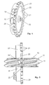
- Fig. 1 shows a perspective view of the first number roller 20 of a roller counter for consumption meter high sensitivity and accuracy.
- the number roller 20 has a central opening 25, with which it is plugged with another number of rollers on a common axis.
- a wide cylindrical surface 24 carries numerals from zero to nine.
- the number roller 20 has a circumferential toothing with narrow teeth 21, which with a screw 10 (FIG. Fig. 2 ) comb.
- the teeth 21 have a bevelled tooth flank 22 and a non-bevelled tooth flank 22 '. Details of this can be found in the Fig. 2 and 3 ,
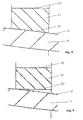
- Fig. 1 and especially the Fig. 2 and 3 can recognize the beveled tooth flank 22 of a tooth 21 and the non-tapered tooth edge 22 'of an adjacent tooth a cone that facilitates the ejection of the finished sprayed wheel 20 from its injection mold, as usual in the prior art, the separation surface of the mold with the end face 23 of the toothing coincides.
- Fig. 2 shows a schematic and partially sectional view of a worm gear consisting of a worm 10 and serving as a worm wheel number 20.
- the worm 10 has flights 11.
- a vertical section is drawn through the worm threads 11 of the worm 10 and the teeth 21 of the worm wheel 20.
- the bevelled tooth flanks 22 of the teeth 21 are oriented parallel to the flanks 12 of the worm threads 11.
- Fig. 3 shows this in an enlarged view. Thanks to the parallelism between the tooth flanks 22 of the teeth 21 and the flanks 12 the worm threads 11 results in a wide engagement surface, which slides over any roughness of the tooth and screw flanks with low friction.
Landscapes
- Physics & Mathematics (AREA)
- Fluid Mechanics (AREA)
- General Physics & Mathematics (AREA)
- Gears, Cams (AREA)
- Transmission Devices (AREA)
- Moulds For Moulding Plastics Or The Like (AREA)
- Gear Transmission (AREA)
- Road Repair (AREA)
- Treatment Of Fiber Materials (AREA)
- Treatment Of Steel In Its Molten State (AREA)
- Vending Machines For Individual Products (AREA)
- Nonmetallic Welding Materials (AREA)
- Spinning Or Twisting Of Yarns (AREA)
- Extrusion Moulding Of Plastics Or The Like (AREA)
Description
- Die Erfindung betrifft Rollenzählwerke für Verbrauchszähler mit hoher Empfindlichkeit und Genauigkeit gemäß dem Oberbegriff des Anspruchs 1.
- Verbrauchszähler, beispielsweise Wasserzähler, Gaszähler, Kilowattstundenzähler usw. sind überwiegend mit einem mechanischen Rollenzählwerk ausgerüstet, welches den Verbrauch aufsummiert. Diese Rollenzählwerke bestehen aus einer Mehrzahl von Zahlenrollen, die nebeneinander auf einer gemeinsamen Achse angeordnet sind, dem sogenannten Rollenpaket. Am Umfang sind die Zahlenrollen mit den Ziffern 0 bis 9 beschriftet. Zwischengetriebe sorgen für eine zehnfache Untersetzung. Eine Besonderheit stellt die erste Zahlenrolle dar. Sie wird mit Hilfe eines Schneckengetriebes kontinuierlich angetrieben. Zu diesem Zweck ist sie mit einer Vielzahl von Zähnen ausgerüstet, die mit dem Schneckengang einer Schnecke kämmen.
- Schneckengetriebe zeichnen sich durch einen hohen Untersetzungsfaktor aus. Des weiteren sind sie tolerant bezüglich eines Axialversatzes des Schneckenrades. Die Schnecke hat Zylinderform und ist ein-, zwei- oder dreigängig. Die Zähne des Schneckenrades sind bei gefrästen Räder mit einer Evolventenform hergestellt und müssen deshalb ca. 30 Zähne haben. Andernfalls muss die Flankenneigung erhöht oder der Eingriff nach außen verschoben werden. Zur Vermeidung der scharf ausladenden Ecken, die zuerst mit vollem Zahndruck zum Eingriff kommen und schaben, werden im klassischen Getriebebau außen zylindrisch abgedrehte Radformen bevorzugt. Allerdings besitzen Schneckengetriebe eine relativ hohe Reibung und damit einen geringen Wirkungsgrad, je nach Ausführungsform Wirkungsgrade zwischen 40 und 80 %.
- Bei den in Verbrauchszählern verwendeten Rollenzählwerken sind alle Bestandteile, ausgenommen die Achsen, aus Kunststoff gespritzt. Dabei werden Kunststoffe mit geringen Reibungskoeffizienten verwendet. Aufgrund der Kleinheit der gespritzten Kunststoffteile einerseits und unvermeidlicher Ungenauigkeiten bei der Herstellung der Spritzformen in Verbindung mit dem unvermeidlichen Abkühlschwund des Kunststoffmaterials und mechanischer Deformationen beim Ausformen, haben die kämmenden Oberflächen des Schneckengetriebes Unebenheiten und Rauhigkeiten, die die Reibung weiter erhöhen.
- Schneckengetriebe für Rollenzählwerke in Verbrauchszählern werden nicht gefräst sondern aus Kunststoff gespritzt. Dabei muss der Formenbauer darauf achten, dass die Spritzteile sich einfach und schnell und vor allem ohne Beschädigung entformen lassen. Werden die Zähne entsprechend der Steigung der Schnecke schräg angestellt, wie es aus der
DE-U 80 03 932 ersichtlich ist, muss das Spritzteil aus der Spritzform herausgedreht werden. Dies ist bei breiten Zähnen wie in derDE-U 80 03 932 dargestellt mit einigem Aufwand verbunden, jedoch möglich. In Rollenzählwerken, bei denen die Verzahnung der ersten Zahlenrolle mit der Schnecke kämmt, sind die Zähne sehr schmal und können deshalb beim drehenden Ausformen leicht deformiert oder gar beschädigt werden. Das ist unbefriedigend. - Es hat nicht an Versuchen gefehlt, die Schneckengetriebe durch andere Getriebe zu ersetzen. So zeigt beispielsweise die
DE-U 201 06 265 einen Schrittschaltantrieb für ein Rollenzählwerk, bei dem die erste Zahlenrolle bzw. ein mit dieser verbundenes koaxiales Stiftrad aus Kunststoff auf seiner freien Stirnseite zehn kreisförmig angeordnete, axiale Schaltstifte aufweist. Diese Schaltstifte stehen wechselweise mit einem kontinuierlich angetriebenen Schaltglied aus Kunststoff eines Messwerkgetriebes in Eingriff, wobei die Drehachse des Schaltgliedes im wesentlichen quer zur Achse des Rollenzählwerks verläuft. Das mit dem Stiftrad in Eingriff stehende Schaltglied weist einen im wesentlichen zylindrischen Sperrkörper auf, der auf einer plan ebenen Stirnfläche einen exzentrisch zu seiner Drehachse angeordneten Schaltzahn mit einer im wesentlichen axialen Schaltfläche und in Drehrichtung unmittelbar hinter dem Schaltzahn eine stirnseitig und in der Mantelfläche offene Schaltnut für einen Schaltstift des sich in Schaltbewegung befindlichen Stiftrades aufweist, und der in Bezug auf die Achse des Stiftrades radial versetzt so angeordnet ist, dass er zwischen zwei Schaltvorgängen mit seiner Stirnfläche und seiner Mantelfläche arretierend zwischen zwei benachbarte Schaltstifte ragt. Auch dieses Sondergetriebe bewirkt eine Drehzahluntersetzung und eine Umlenkung der Drehrichtung um 90°. Allerdings müssen die miteinander kämmenden Räder und Stifte exakt positioniert sein, was die Herstellungskosten erhöht. Auch beruht dieses Sondergetriebe allein auf der gleitenden Bewegung und hat daher einen ebenso geringen Wirkungsgrad wie Schneckengetriebe. - Der vorliegenden Erfindung liegt die Aufgabe zugrunde, ein Rollenzählwerk der eingangs genannten Art anzugeben, dessen Schneckengetriebe verringerte Reibung aufweist und gleichzeitig spritztechnisch günstigere Eigenschaften besitzt.
- Diese Aufgabe wird gelöst durch ein Rollenzählwerk mit den Merkmalen des Anspruchs 1.
- Dank der erfindungsgemäßen Ausgestaltung der Zahnflanken der ersten Zahlenrolle stehen sich jeweils eine angeschrägte und eine nicht angeschrägte Zahnflanke gegenüber. Der so gebildete Konusstumpf ist zur Trennfläche der Spritzform hin offen, so dass die gespritzten Räder mit geringerer Kraft ausgestoßen werden können als derzeit üblich. Dank der verringerten Reibung zwischen Spritzform und Spritzteil wird die Oberfläche der Zahnflanken glatter, wodurch eine geringere Reibung erreicht wird. Der größte Effekt bei der Reibungsverringerung wird jedoch durch die breite Auflagefläche dank der Parallelität zwischen den Schneckengängen der Schnecke und der tragenden Zahnflanke des Schneckenrades beim Vorwärtslauf des Verbrauchszählers erreicht.
- Dank der Optimierung des Rollenzählwerks wird das Messorgan des Verbrauchszählers, bei einem Wasserverbrauchszähler beispielsweise das Flügelrad, weniger gebremst. Das Flügelrad kann daher bei geringeren Durchflüssen anlaufen und auch geringe Durchflüsse mit höherer Genauigkeit anzeigen als derzeit üblich.
- Anhand der Zeichnung soll die Erfindung in Form eines Ausführungsbeispiels näher erläutert werden. Es zeigen
- Fig. 1
- eine erste Zahlenrolle eines Rollenzählwerks für Verbrauchszähler hoher Empfindlichkeit und Genauigkeit in perspektivischer Darstellung,
- Fig. 2
- rein schematisch und teilweise geschnitten ein Schneckengetriebe zum Antreiben der Zahlenrolle gemäß
Fig. 1 , - Fig. 3
- in stark vergrößerter Ausschnittdarstellung einen Schneckengang und einen damit kämmenden Zahn der Zahlenrolle gemäß
Fig. 1 und - Fig. 4
- eine mit
Fig. 3 vergleichbare Darstellung eines Schneckengangs und eines damit kämmenden Zahns der ersten Zahlenrolle eines Rollenzählwerks nach dem Stand der Technik. -
Fig. 1 zeigt in perspektivischer Darstellung die erste Zahlenrolle 20 eines Rollenzählwerks für Verbrauchszähler hoher Empfindlichkeit und Genauigkeit. Die Zahlenrolle 20 besitzt eine zentrale Öffnung 25, mit der sie mit weiteren Zahlenrollen auf eine gemeinsame Achse gesteckt wird. Eine breite Zylinderfläche 24 trägt Ziffern von Null bis Neun. Des weiteren besitzt die Zahlenrolle 20 eine umlaufende Verzahnung mit schmalen Zähnen 21, die mit einer Schnecke 10 (Fig. 2 ) kämmen. - Die Zähne 21 besitzen eine angeschrägte Zahnflanke 22 und eine nicht angeschrägte Zahnflanke 22'. Einzelheiten hierzu ergeben sich aus den
Fig. 2 und3 . - Wie
Fig. 1 und insbesondere dieFig. 2 und3 erkennen lassen, bilden die angeschrägte Zahnflanke 22 des einen Zahns 21 und die nicht angeschrägte Zahnflanke 22' eines benachbarten Zahns einen Konus, der das Ausstoßen des fertig gespritzten Rades 20 aus seiner Spritzform erleichtert, wenn wie beim Stand der Technik üblich die Trennfläche der Spritzform mit der Stirnfläche 23 der Verzahnung übereinstimmt. -
Fig. 2 zeigt in schematischer und teilweise geschnittener Darstellung ein Schneckengetriebe, bestehend aus einer Schnecke 10 und der als Schneckenrad dienenden Zahlenrolle 20. Die Schnecke 10 besitzt Schneckengänge 11. - Zum besseren Verständnis ist durch die Schneckengänge 11 der Schnecke 10 und die Zähne 21 des Schneckenrades 20 ein senkrechter Schnitt gezeichnet. Dadurch erkennt man, dass die angeschrägten Zahnflanken 22 der Zähne 21 parallel zu den Flanken 12 der Schneckengänge 11 orientiert sind.
Fig. 3 zeigt dies in vergrößerter Darstellung. Dank der Parallelität zwischen den Zahnflanken 22 der Zähne 21 und der Flanken 12 der Schneckengänge 11 ergibt sich eine breite Eingriffsfläche, die etwaige Rauhigkeiten der Zahn- und Schneckenflanken mit geringer Reibung übergleitet. - Angeschrägt werden jeweils die Zahnflanken, die beim Vorwärtslaufen des Verbrauchszählers mit den Schneckengängen 12 kämmen. Bei einem etwaigen Rückwärtslauf des Verbrauchszählers kämmen die nicht angeschrägten Zahnflanken 22' mit den Schneckengängen 11. Dabei entsteht höhere Reibung, die jedoch in der Praxis nicht stört, da beim Rückwärtslauf keine Anforderungen an die Messgenauigkeit gefordert sind.
-
Fig. 4 zeigt im Vergleich zurFig. 3 das Zusammenspiel zwischen der Flanke 12 des Schneckengangs 11 und einer nicht angeschrägten Zahnflanke 22' eines Zahns 21' an einer ersten Zahlenrolle nach dem Stand der Technik. Man erkennt, dass die linke Kante des Zahns 21' auf die Schneckenflanke 12 drückt. Dabei entsteht ein hoher Druck, der in einer hohen Reibung resultiert, wobei auch kleine Rauhigkeiten der aus Kunststoff gespritzten Schneckenflanke 12 relativ hohe Bremseffekte bewirken.
Claims (1)
- Rollenzählwerk für Verbrauchszähler hoher Empfindlichkeit und Genauigkeit, umfassend- ein Schneckengetriebe, gebildet durch- eine Schnecke (10)- und ein damit kämmendes Schneckenrad (20) mit Zähnen (21),- das Schneckenrad (20)- ist die erste Zahlenrolle eines Rollenzählwerks- und sitzt mit weiteren Zahlenrollen auf einer gemeinsamen Achse,- alle Räder bzw. Rollen (10, 20) sind aus Kunststoff gespritzt,gekennzeichnet durch die Merkmale:- nur die an der mit der Schnecke (10) bei Vorwärtslauf des Verbrauchszählers kämmenden Flanken (22) der Zähne (21) sind angeschrägt,- die anderen Flanken (22') sind nicht angeschrägt.
Priority Applications (2)
| Application Number | Priority Date | Filing Date | Title |
|---|---|---|---|
| PL06701617T PL1848968T3 (pl) | 2005-02-11 | 2006-01-31 | Bębenkowy mechanizm licznikowy dla liczników zużycia |
| EP06701617A EP1848968B1 (de) | 2005-02-11 | 2006-01-31 | Rollenzählwerk für verbrauchszähler |
Applications Claiming Priority (3)
| Application Number | Priority Date | Filing Date | Title |
|---|---|---|---|
| EP05002926A EP1691176A1 (de) | 2005-02-11 | 2005-02-11 | Rollenzählwerk für Verbrauchszähler |
| PCT/EP2006/000799 WO2006084602A1 (de) | 2005-02-11 | 2006-01-31 | Rollenzählwerk für verbrauchszähler |
| EP06701617A EP1848968B1 (de) | 2005-02-11 | 2006-01-31 | Rollenzählwerk für verbrauchszähler |
Publications (2)
| Publication Number | Publication Date |
|---|---|
| EP1848968A1 EP1848968A1 (de) | 2007-10-31 |
| EP1848968B1 true EP1848968B1 (de) | 2008-11-19 |
Family
ID=34933701
Family Applications (2)
| Application Number | Title | Priority Date | Filing Date |
|---|---|---|---|
| EP05002926A Withdrawn EP1691176A1 (de) | 2005-02-11 | 2005-02-11 | Rollenzählwerk für Verbrauchszähler |
| EP06701617A Expired - Lifetime EP1848968B1 (de) | 2005-02-11 | 2006-01-31 | Rollenzählwerk für verbrauchszähler |
Family Applications Before (1)
| Application Number | Title | Priority Date | Filing Date |
|---|---|---|---|
| EP05002926A Withdrawn EP1691176A1 (de) | 2005-02-11 | 2005-02-11 | Rollenzählwerk für Verbrauchszähler |
Country Status (6)
| Country | Link |
|---|---|
| EP (2) | EP1691176A1 (de) |
| AT (1) | ATE414894T1 (de) |
| DE (1) | DE502006002122D1 (de) |
| ES (1) | ES2316043T3 (de) |
| PL (1) | PL1848968T3 (de) |
| WO (1) | WO2006084602A1 (de) |
Families Citing this family (2)
| Publication number | Priority date | Publication date | Assignee | Title |
|---|---|---|---|---|
| CN101949718B (zh) * | 2010-08-11 | 2012-07-04 | 郑州水业科技发展股份有限公司 | 计数器编码字轮及水表 |
| CN106735046A (zh) * | 2015-11-24 | 2017-05-31 | 浙江大明传动科技有限公司 | 一种锌合金蜗轮的压铸工艺 |
Family Cites Families (2)
| Publication number | Priority date | Publication date | Assignee | Title |
|---|---|---|---|---|
| GB2046965B (en) * | 1979-02-15 | 1984-01-11 | Dai Ichi Seiko Co Ltd | Counter resetting arrangement |
| DE19906693C1 (de) * | 1999-02-18 | 2000-10-12 | Buhler Motor Gmbh | Stellantrieb, insbesondere für Heizungs-, Lüftungs-, oder Klimaklappen im Kfz |
-
2005
- 2005-02-11 EP EP05002926A patent/EP1691176A1/de not_active Withdrawn
-
2006
- 2006-01-31 PL PL06701617T patent/PL1848968T3/pl unknown
- 2006-01-31 DE DE502006002122T patent/DE502006002122D1/de not_active Expired - Lifetime
- 2006-01-31 AT AT06701617T patent/ATE414894T1/de not_active IP Right Cessation
- 2006-01-31 WO PCT/EP2006/000799 patent/WO2006084602A1/de not_active Ceased
- 2006-01-31 ES ES06701617T patent/ES2316043T3/es not_active Expired - Lifetime
- 2006-01-31 EP EP06701617A patent/EP1848968B1/de not_active Expired - Lifetime
Also Published As
| Publication number | Publication date |
|---|---|
| EP1691176A1 (de) | 2006-08-16 |
| EP1848968A1 (de) | 2007-10-31 |
| ATE414894T1 (de) | 2008-12-15 |
| DE502006002122D1 (de) | 2009-01-02 |
| ES2316043T3 (es) | 2009-04-01 |
| WO2006084602A1 (de) | 2006-08-17 |
| PL1848968T3 (pl) | 2009-04-30 |
Similar Documents
| Publication | Publication Date | Title |
|---|---|---|
| EP2291279B1 (de) | Schneckenelemente mit reduziertem energieeintrag beim druckaufbau | |
| DE102008016862B4 (de) | Extruder | |
| EP2852485B1 (de) | Mehrwellenextruder mit selbstreinigenden förderwellen | |
| EP2303543A1 (de) | Verfahren zur konstruktion gleichsinnig rotierender, sich berührender körper und computerprogrammprodukt um das verfahren durchzuführen | |
| EP2864104B1 (de) | Verfahren zur herstellung von kunststoffgranulat, strangpressprofilen oder formteilen | |
| DE2060959A1 (de) | Zahnradgetriebe besonderer Verzahnungsform | |
| DE102013021902B4 (de) | Schmelzepumpe zum Aufbau von Druck zwecks Durchdrücken von Kunststoffschmelze durch ein Werkzeug | |
| EP1804999B1 (de) | Extruder | |
| EP1365906B1 (de) | Schneckenpumpe und mehrschneckenextruder mit einer solchen schneckenpumpe | |
| DE4104397A1 (de) | Innenzahnradpumpe | |
| DE102007059299A1 (de) | Vorrichtung zur Verarbeitung von zu entgasenden Produkten | |
| EP1328730B1 (de) | Füllstücklose innenzahnradpumpe | |
| EP2769621B1 (de) | Anordnung von dichtschließenden Förderschnecken | |
| EP1848968A1 (de) | Rollenzählwerk für verbrauchszähler | |
| DE102008061327A1 (de) | Extruderanordnung | |
| DE2234405A1 (de) | Laeufer fuer einen schraubenkompressor | |
| DE4011248A1 (de) | Schneckenpresse | |
| DE1922121B2 (de) | Lenkgetriebe mit sich änderndem Übersetzungsverhältnis | |
| EP3978108B1 (de) | Einstückiger statischer mischer sowie verfahren zu seiner herstellung | |
| DE2935984A1 (de) | Geraeuscharmes zahnradgetriebe | |
| DE102014118507A1 (de) | Fördervorrichtung | |
| DE102005048847A1 (de) | Fördervorrichtung | |
| EP1409223B1 (de) | Extruder-zahnradpumpen-kombination zur verwendung als einspritzeinheit in spritzgussmaschinen | |
| EP4321775B1 (de) | Zahnrad mit schrägverzahnung | |
| DE3839621A1 (de) | Planetwalzenextruder |
Legal Events
| Date | Code | Title | Description |
|---|---|---|---|
| PUAI | Public reference made under article 153(3) epc to a published international application that has entered the european phase |
Free format text: ORIGINAL CODE: 0009012 |
|
| 17P | Request for examination filed |
Effective date: 20070720 |
|
| AK | Designated contracting states |
Kind code of ref document: A1 Designated state(s): AT BE BG CH CY CZ DE DK EE ES FI FR GB GR HU IE IS IT LI LT LU LV MC NL PL PT RO SE SI SK TR |
|
| RTI1 | Title (correction) |
Free format text: DRUM COUNTER FOR SUPPLY METERS |
|
| DAX | Request for extension of the european patent (deleted) | ||
| GRAP | Despatch of communication of intention to grant a patent |
Free format text: ORIGINAL CODE: EPIDOSNIGR1 |
|
| GRAS | Grant fee paid |
Free format text: ORIGINAL CODE: EPIDOSNIGR3 |
|
| GRAA | (expected) grant |
Free format text: ORIGINAL CODE: 0009210 |
|
| AK | Designated contracting states |
Kind code of ref document: B1 Designated state(s): AT BE BG CH CY CZ DE DK EE ES FI FR GB GR HU IE IS IT LI LT LU LV MC NL PL PT RO SE SI SK TR |
|
| REG | Reference to a national code |
Ref country code: GB Ref legal event code: FG4D Free format text: NOT ENGLISH |
|
| REG | Reference to a national code |
Ref country code: CH Ref legal event code: EP |
|
| REG | Reference to a national code |
Ref country code: IE Ref legal event code: FG4D Free format text: LANGUAGE OF EP DOCUMENT: GERMAN |
|
| REF | Corresponds to: |
Ref document number: 502006002122 Country of ref document: DE Date of ref document: 20090102 Kind code of ref document: P |
|
| REG | Reference to a national code |
Ref country code: ES Ref legal event code: FG2A Ref document number: 2316043 Country of ref document: ES Kind code of ref document: T3 |
|
| LTIE | Lt: invalidation of european patent or patent extension |
Effective date: 20081119 |
|
| PG25 | Lapsed in a contracting state [announced via postgrant information from national office to epo] |
Ref country code: LT Free format text: LAPSE BECAUSE OF FAILURE TO SUBMIT A TRANSLATION OF THE DESCRIPTION OR TO PAY THE FEE WITHIN THE PRESCRIBED TIME-LIMIT Effective date: 20081119 |
|
| REG | Reference to a national code |
Ref country code: PL Ref legal event code: T3 |
|
| NLV1 | Nl: lapsed or annulled due to failure to fulfill the requirements of art. 29p and 29m of the patents act | ||
| PG25 | Lapsed in a contracting state [announced via postgrant information from national office to epo] |
Ref country code: IS Free format text: LAPSE BECAUSE OF FAILURE TO SUBMIT A TRANSLATION OF THE DESCRIPTION OR TO PAY THE FEE WITHIN THE PRESCRIBED TIME-LIMIT Effective date: 20090319 Ref country code: SI Free format text: LAPSE BECAUSE OF FAILURE TO SUBMIT A TRANSLATION OF THE DESCRIPTION OR TO PAY THE FEE WITHIN THE PRESCRIBED TIME-LIMIT Effective date: 20081119 Ref country code: FI Free format text: LAPSE BECAUSE OF FAILURE TO SUBMIT A TRANSLATION OF THE DESCRIPTION OR TO PAY THE FEE WITHIN THE PRESCRIBED TIME-LIMIT Effective date: 20081119 Ref country code: LV Free format text: LAPSE BECAUSE OF FAILURE TO SUBMIT A TRANSLATION OF THE DESCRIPTION OR TO PAY THE FEE WITHIN THE PRESCRIBED TIME-LIMIT Effective date: 20081119 Ref country code: NL Free format text: LAPSE BECAUSE OF FAILURE TO SUBMIT A TRANSLATION OF THE DESCRIPTION OR TO PAY THE FEE WITHIN THE PRESCRIBED TIME-LIMIT Effective date: 20081119 |
|
| REG | Reference to a national code |
Ref country code: IE Ref legal event code: FD4D |
|
| PG25 | Lapsed in a contracting state [announced via postgrant information from national office to epo] |
Ref country code: IE Free format text: LAPSE BECAUSE OF FAILURE TO SUBMIT A TRANSLATION OF THE DESCRIPTION OR TO PAY THE FEE WITHIN THE PRESCRIBED TIME-LIMIT Effective date: 20081119 Ref country code: EE Free format text: LAPSE BECAUSE OF FAILURE TO SUBMIT A TRANSLATION OF THE DESCRIPTION OR TO PAY THE FEE WITHIN THE PRESCRIBED TIME-LIMIT Effective date: 20081119 Ref country code: BG Free format text: LAPSE BECAUSE OF FAILURE TO SUBMIT A TRANSLATION OF THE DESCRIPTION OR TO PAY THE FEE WITHIN THE PRESCRIBED TIME-LIMIT Effective date: 20090219 Ref country code: RO Free format text: LAPSE BECAUSE OF FAILURE TO SUBMIT A TRANSLATION OF THE DESCRIPTION OR TO PAY THE FEE WITHIN THE PRESCRIBED TIME-LIMIT Effective date: 20081119 Ref country code: DK Free format text: LAPSE BECAUSE OF FAILURE TO SUBMIT A TRANSLATION OF THE DESCRIPTION OR TO PAY THE FEE WITHIN THE PRESCRIBED TIME-LIMIT Effective date: 20081119 |
|
| PG25 | Lapsed in a contracting state [announced via postgrant information from national office to epo] |
Ref country code: PT Free format text: LAPSE BECAUSE OF FAILURE TO SUBMIT A TRANSLATION OF THE DESCRIPTION OR TO PAY THE FEE WITHIN THE PRESCRIBED TIME-LIMIT Effective date: 20090420 Ref country code: MC Free format text: LAPSE BECAUSE OF NON-PAYMENT OF DUE FEES Effective date: 20090131 Ref country code: SE Free format text: LAPSE BECAUSE OF FAILURE TO SUBMIT A TRANSLATION OF THE DESCRIPTION OR TO PAY THE FEE WITHIN THE PRESCRIBED TIME-LIMIT Effective date: 20090219 |
|
| PLBE | No opposition filed within time limit |
Free format text: ORIGINAL CODE: 0009261 |
|
| STAA | Information on the status of an ep patent application or granted ep patent |
Free format text: STATUS: NO OPPOSITION FILED WITHIN TIME LIMIT |
|
| 26N | No opposition filed |
Effective date: 20090820 |
|
| REG | Reference to a national code |
Ref country code: FR Ref legal event code: ST Effective date: 20091030 |
|
| PG25 | Lapsed in a contracting state [announced via postgrant information from national office to epo] |
Ref country code: BE Free format text: LAPSE BECAUSE OF NON-PAYMENT OF DUE FEES Effective date: 20090131 |
|
| PG25 | Lapsed in a contracting state [announced via postgrant information from national office to epo] |
Ref country code: FR Free format text: LAPSE BECAUSE OF NON-PAYMENT OF DUE FEES Effective date: 20090202 |
|
| PG25 | Lapsed in a contracting state [announced via postgrant information from national office to epo] |
Ref country code: AT Free format text: LAPSE BECAUSE OF NON-PAYMENT OF DUE FEES Effective date: 20090131 |
|
| REG | Reference to a national code |
Ref country code: CH Ref legal event code: PL |
|
| GBPC | Gb: european patent ceased through non-payment of renewal fee |
Effective date: 20100131 |
|
| PG25 | Lapsed in a contracting state [announced via postgrant information from national office to epo] |
Ref country code: LI Free format text: LAPSE BECAUSE OF NON-PAYMENT OF DUE FEES Effective date: 20100131 Ref country code: GR Free format text: LAPSE BECAUSE OF FAILURE TO SUBMIT A TRANSLATION OF THE DESCRIPTION OR TO PAY THE FEE WITHIN THE PRESCRIBED TIME-LIMIT Effective date: 20090220 Ref country code: CH Free format text: LAPSE BECAUSE OF NON-PAYMENT OF DUE FEES Effective date: 20100131 |
|
| PG25 | Lapsed in a contracting state [announced via postgrant information from national office to epo] |
Ref country code: GB Free format text: LAPSE BECAUSE OF NON-PAYMENT OF DUE FEES Effective date: 20100131 |
|
| PG25 | Lapsed in a contracting state [announced via postgrant information from national office to epo] |
Ref country code: LU Free format text: LAPSE BECAUSE OF NON-PAYMENT OF DUE FEES Effective date: 20090131 |
|
| PG25 | Lapsed in a contracting state [announced via postgrant information from national office to epo] |
Ref country code: HU Free format text: LAPSE BECAUSE OF FAILURE TO SUBMIT A TRANSLATION OF THE DESCRIPTION OR TO PAY THE FEE WITHIN THE PRESCRIBED TIME-LIMIT Effective date: 20090520 |
|
| PG25 | Lapsed in a contracting state [announced via postgrant information from national office to epo] |
Ref country code: TR Free format text: LAPSE BECAUSE OF FAILURE TO SUBMIT A TRANSLATION OF THE DESCRIPTION OR TO PAY THE FEE WITHIN THE PRESCRIBED TIME-LIMIT Effective date: 20081119 |
|
| PG25 | Lapsed in a contracting state [announced via postgrant information from national office to epo] |
Ref country code: CY Free format text: LAPSE BECAUSE OF FAILURE TO SUBMIT A TRANSLATION OF THE DESCRIPTION OR TO PAY THE FEE WITHIN THE PRESCRIBED TIME-LIMIT Effective date: 20081119 |
|
| PGFP | Annual fee paid to national office [announced via postgrant information from national office to epo] |
Ref country code: IT Payment date: 20120125 Year of fee payment: 7 |
|
| PGFP | Annual fee paid to national office [announced via postgrant information from national office to epo] |
Ref country code: DE Payment date: 20130124 Year of fee payment: 8 Ref country code: ES Payment date: 20130122 Year of fee payment: 8 Ref country code: CZ Payment date: 20130121 Year of fee payment: 8 |
|
| PGFP | Annual fee paid to national office [announced via postgrant information from national office to epo] |
Ref country code: PL Payment date: 20130108 Year of fee payment: 8 Ref country code: SK Payment date: 20130122 Year of fee payment: 8 |
|
| REG | Reference to a national code |
Ref country code: DE Ref legal event code: R119 Ref document number: 502006002122 Country of ref document: DE |
|
| REG | Reference to a national code |
Ref country code: SK Ref legal event code: MM4A Ref document number: E 4970 Country of ref document: SK Effective date: 20140131 |
|
| PG25 | Lapsed in a contracting state [announced via postgrant information from national office to epo] |
Ref country code: DE Free format text: LAPSE BECAUSE OF NON-PAYMENT OF DUE FEES Effective date: 20140801 Ref country code: CZ Free format text: LAPSE BECAUSE OF NON-PAYMENT OF DUE FEES Effective date: 20140131 |
|
| REG | Reference to a national code |
Ref country code: DE Ref legal event code: R119 Ref document number: 502006002122 Country of ref document: DE Effective date: 20140801 |
|
| PG25 | Lapsed in a contracting state [announced via postgrant information from national office to epo] |
Ref country code: SK Free format text: LAPSE BECAUSE OF NON-PAYMENT OF DUE FEES Effective date: 20140131 |
|
| REG | Reference to a national code |
Ref country code: PL Ref legal event code: LAPE |
|
| PG25 | Lapsed in a contracting state [announced via postgrant information from national office to epo] |
Ref country code: PL Free format text: LAPSE BECAUSE OF NON-PAYMENT OF DUE FEES Effective date: 20140131 |
|
| REG | Reference to a national code |
Ref country code: ES Ref legal event code: FD2A Effective date: 20150901 |
|
| PG25 | Lapsed in a contracting state [announced via postgrant information from national office to epo] |
Ref country code: ES Free format text: LAPSE BECAUSE OF NON-PAYMENT OF DUE FEES Effective date: 20140201 |
|
| PG25 | Lapsed in a contracting state [announced via postgrant information from national office to epo] |
Ref country code: IT Free format text: LAPSE BECAUSE OF NON-PAYMENT OF DUE FEES Effective date: 20140131 |