EP1848874B1 - Installation kit for equipping a case as a multifunctional, portable security system, and case comprising such an installation kit - Google Patents
Installation kit for equipping a case as a multifunctional, portable security system, and case comprising such an installation kit Download PDFInfo
- Publication number
- EP1848874B1 EP1848874B1 EP06708089A EP06708089A EP1848874B1 EP 1848874 B1 EP1848874 B1 EP 1848874B1 EP 06708089 A EP06708089 A EP 06708089A EP 06708089 A EP06708089 A EP 06708089A EP 1848874 B1 EP1848874 B1 EP 1848874B1
- Authority
- EP
- European Patent Office
- Prior art keywords
- case
- security
- installation kit
- igniter
- liquid
- Prior art date
- Legal status (The legal status is an assumption and is not a legal conclusion. Google has not performed a legal analysis and makes no representation as to the accuracy of the status listed.)
- Active
Links
Images


Classifications
-
- E—FIXED CONSTRUCTIONS
- E05—LOCKS; KEYS; WINDOW OR DOOR FITTINGS; SAFES
- E05G—SAFES OR STRONG-ROOMS FOR VALUABLES; BANK PROTECTION DEVICES; SAFETY TRANSACTION PARTITIONS
- E05G1/00—Safes or strong-rooms for valuables
- E05G1/14—Safes or strong-rooms for valuables with means for masking or destroying the valuables, e.g. in case of theft
Definitions
- the invention relates to a built-in kit for equipping a suitcase as a multifunctional, portable security system according to the preamble of patent claim 1 and a suitably equipped as a multifunctional portable security system suitcase according to the preamble of claim.
- the security cases have a safe area, a protection system and an access opening which can be closed and which, when opened, makes the security case accessible.
- the protection system is intended to protect the owner or the owner of the valuables against misuse of the valuables if they are lost in the event of a theft. This is done by the valuables are automatically neutralized or devalued in such a case, in particular colored.
- the corresponding known protection systems are expensive and expensive.
- the publication font US-A1-2004 / 0154500 discloses a trigger device with two gas cartridges, wherein the first gas pressure cartridge is opened by an electrical signal to a solenoid valve and the resulting gas pushes the second gas pressure cartridge in a needle, so that the gas of this second gas pressure cartridge is conveyed via a line in an ink reservoir.
- the triggering device must be connected via an outlet valve of the ink reservoir to a distribution device for the ink, respectively, so that the ink to a valuables compartment can reach, which is formed in the bottom of the suitcase provided for this purpose.
- the publication font US-A1-2003 / 0005882 discloses a triggering device which may be screwed separately from the valuables compartment in a portable drawer above the valuables compartment.
- An electrical signal triggers a pyrotechnic actuator, which in turn triggers a propellant, creating a pressure in an ink reservoir.
- a flexible hose in the ink reservoir is to ensure that the distributor device distributes ink rather than propellant gas.
- the invention is intended to allow a high degree of flexibility in handling and to provide a security system that is inexpensive, and that allows retrofitting or equipping suitcases and similar containers of similar construction and construction and size.
- a new approach is taken, which makes it possible to offer a high level of security at a reasonable price.
- This one goes out conventional suitcases, as offered in numerous shapes, sizes and materials.
- Such suitcases can be equipped or retrofitted by means of an inventive installation kit or kit to a multi-functional, portable security system.
- the installation kit ensures a high degree of safety, which can be further increased by numerous optional measures.
- a standard suitcase which can also serve as a piece of luggage for normal luggage, the security system is inexpensive and provides additional security, since it is not apparent to outsiders that the case is a security system for transporting valuables or that there are valuables in the suitcase.
- the arrangement of a distributor plate according to the invention simplifies the manufacture and facilitates repairs, since it makes it superfluous to mount a plurality of individual sub-lines for the liquid.
- the means for their protection are reinforced or brought from an inactive, that is to say deactivated, state into an armed or activated state. If the means for protecting the valuables are activated, in an emergency, that is, if the suitcase or its contents are illegally handled or operated, the neutralization or coloring of the valuables is triggered, and the latter are neutralized or devalued by the liquid : By this is meant that the valuables are at least temporarily changed, damaged or destroyed. This neutralization may also be such that the valuables may retain or recover their value for the legitimate owner or owner.
- the installation kit includes a receiving area for storing valuables.
- the receiving area is accessible via an access opening, which can be covered with a lid or, depending on the embodiment, can be closed.
- the protection means with an igniter that can be triggered by the application of an electrical signal.
- an ink module with a liquid for coloring the valuables.
- the ink module is connected to the igniter via a pressure connection and has an exit area for dispensing the liquid.
- a gas pressure cartridge which is connected to the igniter, provides the necessary gas pressure after triggering the igniter to carry liquid from the ink module in the liquid passage of the distributor plate and from there through the outlet openings of the distributor plate in the direction of the valuables, so that they are colored.
- the cover for covering the access opening is designed so that it delays immediate access to the valuables in the receiving area. In unauthorized access without prior transfer of the security circuit in the defused state can be triggered by the security circuit neutralizing or coloring the valuables.
- the protection system may include further protection means or security features, which are arranged either in the receiving area or in the suitcase. Such protections are used to protect the case against various types of attacks or in a variety of situations.
- the protection system comprises a safety circuit which is connectable to the igniter and in an emergency situation provides the electrical signal for triggering the igniter, and a safety interface which makes it possible to reinforce the safety circuit as needed or to bring it to a disarmed state. Additionally, the protection system may include an energy source or energy storage for its supply of energy.
- the security system or the protective system of the suitcase formed by the installation kit and the case is armored by a pocket PC or a computer via an interface or set clear or defused.
- the protection system via the security interface is able to establish a further communication possibility between the security circuit and an external device, preferably a portable computer.
- the safety circuit used for this purpose is an electrical / electronic circuit. This safety circuit is part of the protection system.
- the mentioned security interface can be designed to establish a contactless connection and comprise a transmitter and a receiver, which is preferably an infrared connection and this connection enables encrypted communication. But there are also transmitter and receiver facilities possible, working with RF or other waves.
- an interface may be provided to read an RF-ID chip or barcode to allow release (opening) only.
- RF-ID chip or barcode may be located at the destination (for example, at a bank). Only after the detection of the RF-ID chip or the barcode by the security circuit is then released the security system.
- the protective system may comprise surface protection means which can be inserted or installed in the case and enclose the receiving area. These means may be electrically connectable to the security circuit to trigger neutralization or staining of the valuables via the security circuit in an attempt to damage or penetrate the case.
- surface protection protective films, nets, mesh or fabric may be used to provide protection against break-up, cut-through or puncture.
- the protection system can also include a shock sensor, which can be installed in the case as an additional protective measure.
- the impact sensor is electrically connectable to the safety circuit and triggers the neutralization or coloring of the valuables at a predetermined number or frequency of shocks and / or shocks on the safety circuit.
- a motion sensor may be provided which is deactivated by a manipulator or a transport of the suitcase by authorized persons.
- seal or seal of a mechanical or electronic nature to the case or receptacle.
- a seal or seal is not primarily intended to prevent opening of the container, but an unauthorized, but non-violent opening, for example, by a person authorized to transport the suitcase, to determine.
- the protection system may be designed so that access to the receiving area is possible with or without operation of an additional auxiliary element such as a (non-contact) key.
- Additional security can be achieved with additional modules that generate smoke when the security system is tampered with. This has a signal effect and prevents a culprit takes the suitcase.
- an airbag system is arranged in or on the suitcase.
- Such an airbag system must be designed so that it can be activated or activated in the event of unauthorized handling of the safety system. Due to the volume magnification occurring when the airbag system is actuated, unauthorized manipulations of the safety system are made more difficult and may possibly prevent a culprit from taking the suitcase with him.
- the new case together with the new kit, serves as a multifunctional, portable security system.
- the case is designed so that its outer cover part and its outer bottom part in the closed state protect the receiving area in the interior against moisture and mechanical damage and preferably also against high temperatures.
- the case is preferably a conventional, sufficiently rigid case, for example, a case, which is preferably made of a plastic material.
- the case may include all the protective measures described above with respect to the new installation kit.
- the case can establish a communication connection between the security circuit and an external device, preferably a portable computer, via the security interface.
- an external device preferably a portable computer
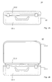
- FIG. 1A to Fig. 1C show various views of an embodiment of the invention.
- Fig. 1A is to recognize a suitcase 11, which is equipped by means of an installation kit according to the invention as a multifunctional, portable security system 10.
- the case 11 is shown in the closed state.
- the case 11 has an outer bottom part 11.1 and an outer lid part 11.2, which are pivotally connected to each other.
- a handle and two snap fasteners or snap locks are indicated.
- Fig. 1A is indicated by dashed lines located in a suitcase 11 receiving area.
- This receiving area is located substantially in the interior of the outer bottom part 11.1 and is designed to hold objects of value 13 shown schematically (see FIG Fig. 1C ).
- the receiving area is accessible via an access opening when the outer lid part 11.2 is opened, as in Fig. 1B shown.
- the receiving area is enclosed by a cassette which has a base tray 12.1 and a tray lid 12.2 for covering the access opening. It can also be provided several receiving areas.
- the receiving area can be secured by one or more security means.
- an igniter 14 with a diaphragm is provided for this purpose, which can be triggered by the application of an electrical signal, as shown in FIG Fig. 1C is shown.
- An ink module 17 containing a liquid for neutralizing the valuables 13 communicates with the igniter 14 and a distributor plate 18.
- ink module is also understood to mean a module with a liquid other than ink or with another flowable medium
- liquid should also be understood to mean another fluid medium
- coloring of the valuables 13 should also be understood to mean another change which can be caused by a flowable medium, for example etching.
- ink modules in particular, it may be provided to configure and arrange a plurality of ink modules such that liquid can be dispensed onto the valuables 13 from several directions.
- the ink module 17 has a port for establishing pressure communication with the igniter 14 and an exit region for discharging the fluid.
- the distributor plate 18 has at least one integrated liquid channel, as well as a number of outlet openings for the liquid.
- the distributor plate 18 is manufactured in one piece and can be connected to the outlet region of the ink module 17.
- the ink module 17 forms an assembly with the distributor plate 18, wherein the distributor plate 18 can be connected to the outlet region of the ink module 17 in a pressure-tight manner when attached to the ink module 17.
- a gas pressure cartridge 15 is connected to the igniter 14 so that the igniter 14 is triggered upon application of the electrical signal and a membrane of the igniter (14) severed.
- gas is discharged from the gas pressure cartridge 15 and passed through the pressure connection in the ink module 17.
- the liquid passes from the ink module into the liquid channel of the distributor plate 18 and through the outlet openings of the distributor plate 18 in the direction of the valuables 13.
- Fig. 1C is shown by arrows 19, the coloring of the valuables 13.
- Fig. 1C shows a circuit 20 with a safety interface 16, via which the circuit 20 from an external control element such as a computer 30 is controlled, as shown schematically.
- the external control element 30 essentially serves to bring the protection system from a non-armored or passive state to an armed or active state. Only when the protection system is armed or activated, the detonator 15 is triggered in an unauthorized handling of the security system and initiated the neutralization or coloring of the valuables.
- the Fig. 2A, 2B and 2C show details of another protection system in which the ink module 17 comprises three sub-modules 17.1, 17.2, 17.3. It is also possible a different number of sub-modules and / or a different spatial arrangement of the sub-modules.
- the igniter 14 and an electrical connection 14.1 for the igniter 14 are shown, via which the igniter 14 can be triggered.
- the gas pressure cartridge 15 is shown.
- the distributor plate 18 has according to Fig. 2A to 2C a connection system 18.2.
- the distributor plate 18, more precisely its space or liquid channel 18.1 for carrying out the liquid, is connected to the interior of the ink module 17 via one or more channels 18.3 of the connection system 18.2.
- the connection system 18.2 can serve as a lateral mounting element to connect the distributor plate 18 with the ink modules 17.1 - 17.3 mechanically and "hydraulically".
- FIG. 2A Detail enlarged in the style of a magnifying glass shows a vertical section through the ink module 17.1 and the distributor plate 18. It can be seen that the distributor plate 18 has a lower plate portion 18.5 and an upper plate portion 18.6 which sealingly abut each other.
- the plate parts 18.5, 18.6 limit the aforementioned fluid channel 18.1.
- the outlet openings 18.4 are arranged in the upper plate part 18.6.
- liquid channel 18.1 which may possibly also have a plurality of liquid partial channels connected in parallel, can only be filled via the connection system 18.3 and can only be emptied via the outlet openings 18.4.
- Distributor plates can be made of different materials, in particular of light metal or suitable plastics.
- Fig. 2C shows the distribution plate of the protection system from above, with the liquid channel 18.1, the connection systems 18.2, the outlet openings 18.4 and the upper plate portion 18.6. Shown are dash-lined nine areas of the upper plate portion 18.6, around which the liquid channel 18.1 with the outlet openings 18.4 zigzag-like or meandering extends.
- a bag bag
- These bags have a closure that allows to close the bag with valuables after filling. After closing, such a bag can not be opened without leaving a trace. The recipient of the bag can thus determine if the bag has been opened.
- a special fuse is provided according to the invention, which develops heat after ignition and melts the bag. As a result, the valuables can also be reached by the ink when they are in a bag.
- the invention now offers the advantage that the necessary fuse can be inserted into the distributor plate 18 or fixed on it.
- a corresponding embodiment is in Fig. 3 indicated.
- Fig. 3 is analogous to Fig. 2C a schematic plan view of another embodiment of a distributor plate 18 is shown.
- Fig. 3 shows the distribution plate 18 of the protection system from above.
- At least one, but preferably two, fuses 22 are provided on the surface of the distributor plate 18. These fuses 22 are preferably arranged meandering.
- the manifold plate has a superficially formed channel into which the fuse / fuses 22 may be inserted.
- a primer 22.1 is provided, which can be ignited via two cables 22.2.
- the two cables 22.2 can be connected to the security circuit 20.
- the safety circuit 20 ignites the primer 22.1 and thus triggers a burning of the fuse / fuses 22. These melt the bags. As a result, the valuables for the ink are reached, which is discharged from the openings 18.4 with pressure.
- the patent US 5,156,272 discloses electric heating wires which, however, are not used to melt the bag or pouch, but to initiate the marking operation by allowing the heating wires to melt the ink reservoir and thereby impregnate a sponge with the exiting ink.
- the sponge is in contact with the valuables.
- the heating wires serve a different purpose and are not - like the inventive fuses - in direct contact with the valuables or a bag enclosing them.
- the case 10 can be mounted on a shelf.
- the shelf can be equipped with an interlocking function.
- a circuit on the shelf takes over at least part of the safety functions or the monitoring of the safety functions. Removal from the shelf can be done for example via a PDA with a suitable interface.
Abstract
Description
Die Erfindung betrifft ein Einbau-Kit zum Ausstatten eines Koffers als multifunktionales, tragbares Sicherheitssystem nach dem Oberbegriff des Patentanspruchs 1 und einen entsprechend als multifunktionales, tragbares Sicherheitssystem ausgestatteten Koffer nach dem Oberbegriff des Patentanspruchs 9.The invention relates to a built-in kit for equipping a suitcase as a multifunctional, portable security system according to the preamble of patent claim 1 and a suitably equipped as a multifunctional portable security system suitcase according to the preamble of claim. 9
Es gibt verschiedenste Sicherheitskoffer zum Transport von schutzbedürftigen Gegenständen, zum Beispiel von Wertsachen wie von Münz- und Notengeld, Wertpapieren, anderen Wertgegenständen wie Edelmetallen und Edelsteinen, geheimzuhaltenden Dokumenten oder ggf. auch Giftstoffen, seltenen Stoffen oder anderweitig abzuschirmendem, zum Beispiel strahlendem Material.There are a variety of security case for transporting vulnerable items, such as valuables such as coins and notes, securities, other valuables such as precious metals and gems, secret documents or possibly also toxins, rare substances or otherwise shielded, for example, radiating material.
Die Sicherheitskoffer weisen einen Tresorbereich, ein Schutzsystem und eine Zugriffsöffnung auf, die geschlossen werden kann und die in geöffnetem Zustand den Sicherheitskoffer zugänglich macht.The security cases have a safe area, a protection system and an access opening which can be closed and which, when opened, makes the security case accessible.
Das Schutzsystem dient dazu, den Eigentümer oder Besitzer der Wertsachen vor einem Missbrauch der Wertsachen zu schützen, wenn diese bei einem Diebstahl abhanden kommen. Dies geschieht, indem die Wertsachen in einem solchen Fall automatisch neutralisiert bzw. devaluiert, insbesondere eingefärbt werden. Die entsprechenden bekannten Schutzsysteme sind teuer und aufwendig.The protection system is intended to protect the owner or the owner of the valuables against misuse of the valuables if they are lost in the event of a theft. This is done by the valuables are automatically neutralized or devalued in such a case, in particular colored. The corresponding known protection systems are expensive and expensive.
Es gibt, wie schon erwähnt, verschiedenartige Wertgegenstände zu transportieren. Je nach Art der Wertgegenstände müssen die Koffer unterschiedliche Grössen haben. Ausserdem können unterschiedlichste Sicherheitsvorschriften gelten. In der Praxis sind daher eine grosse Zahl von verschiedensten Koffern im Einsatz.As already mentioned, there are various valuables to transport. Depending on the type of valuables, the suitcases must have different sizes. In addition, various safety regulations can apply. In practice, therefore, a large number of different suitcases in use.
Wichtig ist bei derartigen Koffern, dass sie den entsprechenden Sicherheitsvorschriften entsprechen, tragbar und vor allem flexibel einsetzbar sind. Heutige Koffer erfüllen diese Kriterien nur teilweise. Ausserdem sind die Koffer heutzutage relativ teuer.It is important in such suitcases that they comply with the relevant safety regulations, are portable and above all flexible use. Today's suitcases meet these criteria only partially. In addition, the cases are relatively expensive nowadays.
Ausserdem wird immer noch ein Hauptaugenmerk auf die Sicherheit und Stabilität des eigentlichen Koffers gelegt.In addition, a main focus is still placed on the safety and stability of the actual suitcase.
Die Veröffentlichungsschrift
Auch die Veröffentlichungsschrift
Es ist Aufgabe der Erfindung,
- ein Einbau-Kit zum Ausstatten eines Koffers als multifunktionales, tragbares Sicherheitssystem zu schaffen, der eine hohe Sicherheit gewährleistet, möglichst universell verwendbar ist und einfach hergestellt und gehandhabt werden kann, und
- einen mit einem solchen Einbau-Kit ausgestatteten Koffer vorzuschlagen.
- to provide a built-in kit for equipping a suitcase as a multifunctional portable security system, which ensures a high level of security, is as universal as possible and can be easily manufactured and handled, and
- to propose a case equipped with such an installation kit.
Die Erfindung soll eine hohe Flexibilität in der Handhabbarkeit ermöglichen und ein Sicherheitssystem schaffen, das kostengünstig ist, und das ein Nachrüsten oder Ausrüsten von Koffern und ähnlichen Gebinden ähnlicher Bau- und Machart und Grösse ermöglicht.The invention is intended to allow a high degree of flexibility in handling and to provide a security system that is inexpensive, and that allows retrofitting or equipping suitcases and similar containers of similar construction and construction and size.
Die Lösung dieser Aufgabe erfolgt erfindungsgemäss
- für ein Einbau-Kit durch die kennzeichnenden Merkmale des Anspruchs 1, und
- für, einen Koffer durch die kennzeichnenden Merkmale des Anspruchs 9.
- for a built-in kit by the characterizing features of claim 1, and
- for, a suitcase by the characterizing features of claim 9.
Bevorzugte Weiterbildungen des Sicherheitssystems sind durch die abhängigen Ansprüche definiert.Preferred developments of the safety system are defined by the dependent claims.
Gemäss der Erfindung wird ein neuer Weg beschritten, der es ermöglicht, eine hohe Sicherheit bei einem vertretbaren Preis zu bieten. Dabei geht man aus von konventionellen Koffern, wie sie in zahlreichen Formen, Grössen und Materialien angeboten werden. Derartige Koffer lassen sich mittels eines erfindunggemässen Einbau-Kits bzw. Bausatzes zu einem multifunktionalen, tragbaren Sicherheitssystem ausrüsten bzw. nachrüsten. Der Einbau-Kit gewährleistet eine hohe Sicherheit, die durch zahlreiche optionale Massnahmen weiter erhöht werden kann. Durch die Verwendung eines üblichen Koffers, der auch als Gepäckstück für normales Reisegepäck dienen kann, ist das Sicherheitssystem kostengünstig und man erzielt eine zusätzliche Sicherheit, da für Aussenstehende nicht zu erkennen ist, dass es sich beim Koffer um ein Sicherheitssystem zum Transport von Wertgegenständen handelt bzw. dass sich im Koffer Wertgegenstände befinden.According to the invention, a new approach is taken, which makes it possible to offer a high level of security at a reasonable price. This one goes out conventional suitcases, as offered in numerous shapes, sizes and materials. Such suitcases can be equipped or retrofitted by means of an inventive installation kit or kit to a multi-functional, portable security system. The installation kit ensures a high degree of safety, which can be further increased by numerous optional measures. By using a standard suitcase, which can also serve as a piece of luggage for normal luggage, the security system is inexpensive and provides additional security, since it is not apparent to outsiders that the case is a security system for transporting valuables or that there are valuables in the suitcase.
Die Anordnung einer erfindungsgemässen Verteilerplatte vereinfacht die Herstellung und erleichtert Reparaturen, da sie es überflüssig macht, eine Vielzahl einzelner Teilleitungen für die Flüssigkeit zu montieren.The arrangement of a distributor plate according to the invention simplifies the manufacture and facilitates repairs, since it makes it superfluous to mount a plurality of individual sub-lines for the liquid.
Befinden sich in einem Aufnahmebereich Wertgegenstände, so werden die Mittel zu deren Schutz armiert bzw. aus einem inaktiven, dass heisst deaktivierten Zustand in einen armierten bzw. aktivierten Zustand gebracht. Sind die Mittel zum Schutz der Wertgegenstände aktiviert, so wird in einem Notfall, dass heisst, wenn der Koffer oder sein Inhalt unrechtmässig behändigt oder betätigt wird, die Neutralisation bzw. Einfärbung der Wertgegenstände ausgelöst, und die Letzteren werden durch die Flüssigkeit neutralisiert bzw. devaluiert: Darunter ist zu verstehen, dass die Wertgegenstände mindestens temporär verändert, beschädigt oder zerstört werden. Dieses Neutralisieren kann auch so erfolgen, dass die Wertgegenstände ihren Wert für den rechtmässigen Besitzer oder Eigentümer behalten oder wieder erlangen können.If there are valuables in a receiving area, the means for their protection are reinforced or brought from an inactive, that is to say deactivated, state into an armed or activated state. If the means for protecting the valuables are activated, in an emergency, that is, if the suitcase or its contents are illegally handled or operated, the neutralization or coloring of the valuables is triggered, and the latter are neutralized or devalued by the liquid : By this is meant that the valuables are at least temporarily changed, damaged or destroyed. This neutralization may also be such that the valuables may retain or recover their value for the legitimate owner or owner.
Das Einbau-Kit umfasst einen Aufnahmebereich zur Aufnahme von Wertgegenständen. Der Aufnahmebereich ist über eine Zugangsöffnung zugänglich, die mit einem Deckel abdeckbar bzw. je nach Ausführungsform verschliessbar ist. Zusätzlich ist ein Schutzsystem vorhanden, das Schutzmittel mit einem Zünder umfasst, der durch das Anlegen eines elektrischen Signals ausgelöst werden kann. Es ist weiterhin ein Tintenmodul mit einer Flüssigkeit zum Einfärben der Wertgegenstände vorgesehen. Das Tintenmodul ist über eine Druckverbindung mit dem Zünder verbunden und weist einen Austrittsbereich zum Abgeben der Flüssigkeit auf. Es ist eine Verteilerplatte vorgesehen, die einstückig hergestellt ist und mindestens einen integrierten Flüssigkeitskanal sowie eine Anzahl von Austrittsöffnungen für die Flüssigkeit aufweist. Die Verteilerplatte kann mit dem Austrittsbereich des Tintenmoduls verbunden werden. Eine Gasdruckpatrone, die mit dem Zünder verbunden ist, liefert nach dem Auslösen des Zünders den nötigen Gasdruck, um Flüssigkeit aus dem Tintenmodul in den Flüssigkeitskanal der Verteilerplatte und von dort durch die Austrittsöffnungen der Verteilerplatte in Richtung der Wertgegenstände zu befördern, damit diese eingefärbt werden.The installation kit includes a receiving area for storing valuables. The receiving area is accessible via an access opening, which can be covered with a lid or, depending on the embodiment, can be closed. In addition, there is a protection system, the protection means with an igniter that can be triggered by the application of an electrical signal. There is further provided an ink module with a liquid for coloring the valuables. The ink module is connected to the igniter via a pressure connection and has an exit area for dispensing the liquid. It is a distributor plate provided, which is made in one piece and having at least one integrated liquid channel and a number of outlet openings for the liquid. The distributor plate can be connected to the exit region of the ink module. A gas pressure cartridge, which is connected to the igniter, provides the necessary gas pressure after triggering the igniter to carry liquid from the ink module in the liquid passage of the distributor plate and from there through the outlet openings of the distributor plate in the direction of the valuables, so that they are colored.
Eine vorteilhafte Anordnung erhält man, wenn das Tintenmodul mit der Verteilerplatte eine Baugruppe bildet, wobei die Verteilerplatte beim Befestigen an dem Tintenmodul druckdicht mit dem Austrittsbereich des Tintenmoduls verbindbar ist. Die Dichtheit sollte möglichst über einen grossen Temperaturbereich aufrechterhalten werden.An advantageous arrangement is obtained when the ink module with the distributor plate forms an assembly, wherein the distributor plate when attached to the ink module pressure-tight with the outlet region of the ink module is connectable. The tightness should be maintained as possible over a wide temperature range.
Es ist günstig, wenn der Deckel zum Abdecken der Zugangsöffnung so ausgelegt ist, dass er einen unmittelbaren Zugriff auf die Wertgegenstände im Aufnahmebereich verzögert. Bei unerlaubtem Zugriff ohne vorheriges Überführen der Sicherheitsschaltung in den entschärften Zustand kann dazu durch die Sicherheitsschaltung das Neutralisieren bzw. Einfärben der Wertgegenstände ausgelöst werden.It is advantageous if the cover for covering the access opening is designed so that it delays immediate access to the valuables in the receiving area. In unauthorized access without prior transfer of the security circuit in the defused state can be triggered by the security circuit neutralizing or coloring the valuables.
Das Schutzsystem kann weitere Schutzmittel bzw. Sicherheitsmerkmale umfassen, die entweder im Aufnahmebereich oder im Koffer angeordnet sind. Solche Schutzmittel dienen dazu, den Koffer gegen verschiedenste Arten von Angriffen oder in den verschiedensten Situationen zu schützen.The protection system may include further protection means or security features, which are arranged either in the receiving area or in the suitcase. Such protections are used to protect the case against various types of attacks or in a variety of situations.
Das Schutzsystem umfasst eine Sicherheitsschaltung, die mit dem Zünder verbindbar ist und in einer Notsituation das elektrische Signal zum Auslösen des Zünders bereitstellt, sowie eine Sicherheitsschnittstelle, die es ermöglicht, die Sicherheitsschaltung je nach Bedarf zu armieren oder in einen entschärften Zustand zu bringen. Zusätzlich kann das Schutzsystem eine Energiequelle oder einen Energiespeicher zu seiner Versorgung mit Energie aufweisen.The protection system comprises a safety circuit which is connectable to the igniter and in an emergency situation provides the electrical signal for triggering the igniter, and a safety interface which makes it possible to reinforce the safety circuit as needed or to bring it to a disarmed state. Additionally, the protection system may include an energy source or energy storage for its supply of energy.
In einer besonders bevorzugten Ausführungsform wird das vom Einbau-Kit und dem Koffer gebildete Sicherheitssystem bzw. das Schutzsystem des Koffers durch einen Pocket-PC oder einen Computer über eine Schnittstelle armiert bzw. scharf gestellt oder entschärft. Vorteilhafterweise ist das Schutzsystem über die Sicherheitsschnittstelle in der Lage, eine weitere Kommunikationsmöglichkeit zwischen der Sicherheitsschaltung und einem externen Gerät, vorzugsweise einem tragbaren Computer, aufzubauen.In a particularly preferred embodiment, the security system or the protective system of the suitcase formed by the installation kit and the case is armored by a pocket PC or a computer via an interface or set clear or defused. Advantageously, the protection system via the security interface is able to establish a further communication possibility between the security circuit and an external device, preferably a portable computer.
Vorzugsweise handelt es sich bei der hierzu benutzten Sicherheitsschaltung um eine elektrische/elektronische Schaltung. Diese Sicherheitsschaltung ist ein Teil des Schutzsystems.Preferably, the safety circuit used for this purpose is an electrical / electronic circuit. This safety circuit is part of the protection system.
Die erwähnte Sicherheitsschnittstelle kann zum Aufbau einer kontaktlosen Verbindung ausgelegt sein und einen Sender sowie einen Empfänger umfassen, wobei es sich vorzugsweise um eine Infrarot-Verbindung handelt und diese Verbindung eine verschlüsselte Kommunikation ermöglicht. Es sind aber auch Sender- und Empfängereinrichtungen möglich, die mit RF oder anderen Wellen arbeiten.The mentioned security interface can be designed to establish a contactless connection and comprise a transmitter and a receiver, which is preferably an infrared connection and this connection enables encrypted communication. But there are also transmitter and receiver facilities possible, working with RF or other waves.
Im Weiteren kann eine Schnittstelle vorgesehen sein, um einen RF-ID Chip oder einen Barcode zu lesen, um erst dann eine Freigabe (das Öffnen) zu erlauben. Ein solcher RF-ID Chip oder Barcode kann am Zielort (zum Beispiel bei einer Bank) angeordnet sein. Erst nach dem Erkennen des RF-ID Chips oder des Barcodes durch die Sicherheitsschaltung erfolgt dann eine Freigabe des Sicherheitssystems.Furthermore, an interface may be provided to read an RF-ID chip or barcode to allow release (opening) only. Such RF-ID chip or barcode may be located at the destination (for example, at a bank). Only after the detection of the RF-ID chip or the barcode by the security circuit is then released the security system.
Als zusätzliche Schutzmassnahme kann das Schutzsystem Mittel zum Oberflächenschutz umfassen, die in den Koffer einlegbar oder einbaubar sind und den Aufnahmebereich umschliessen. Diese Mittel können elektrisch mit der Sicherheitsschaltung verbindbar sein, um bei einem Versuch, den Koffer zu beschädigen oder zu durchdringen, über die Sicherheitsschaltung das Neutralisieren bzw. Einfärben der Wertgegenstände auszulösen. Als Mittel zum Oberflächenschutz können Schutzfolien, Netze, Gitter oder Gewebe verwendet werden, um einen Schutz gegen Aufbrechen, Durchschneiden oder Durchbohren zu gewähren.As an additional protective measure, the protective system may comprise surface protection means which can be inserted or installed in the case and enclose the receiving area. These means may be electrically connectable to the security circuit to trigger neutralization or staining of the valuables via the security circuit in an attempt to damage or penetrate the case. As a means of surface protection, protective films, nets, mesh or fabric may be used to provide protection against break-up, cut-through or puncture.
Das Schutzsystem kann als zusätzliche Schutzmassnahme auch einen Schlagsensor umfassen, der in den Koffer einbaubar ist. Der Schlagsensor ist elektrisch mit der Sicherheitsschaltung verbindbar und löst bei einer vorgegebenen Anzahl oder Häufigkeit von Schlägen und/oder Erschütterungen über die Sicherheitsschaltung das Neutralisieren bzw. Einfärben der Wertgegenstände aus.The protection system can also include a shock sensor, which can be installed in the case as an additional protective measure. The impact sensor is electrically connectable to the safety circuit and triggers the neutralization or coloring of the valuables at a predetermined number or frequency of shocks and / or shocks on the safety circuit.
Zur weiteren Erhöhung der Sicherheit kann ein Bewegungssensor vorgesehen sein, der bei einer Manipulation oder einem Transport des Koffers durch dazu Befugte deaktiviert wird.To further increase security, a motion sensor may be provided which is deactivated by a manipulator or a transport of the suitcase by authorized persons.
Ein zusätzlicher Schutz der Wertgegenstände kann dadurch erreicht werden, dass für den Koffer oder den Aufnahmebereich eine Versiegelung oder Plombierung mechanischer oder elektronischer Art vorgesehen ist. Mit einer solchen Versiegelung oder Plombierung wird nicht in erster Linie bezweckt, ein Öffnen des Behältnisses zu verhindern, sondern ein unbefugtes, aber gewaltfreies Öffnen, beispielsweise durch eine zum Transport des Koffers befugte Person, feststellen zu können.Additional protection of the valuables can be achieved by providing a seal or seal of a mechanical or electronic nature to the case or receptacle. With such a seal or seal is not primarily intended to prevent opening of the container, but an unauthorized, but non-violent opening, for example, by a person authorized to transport the suitcase, to determine.
Das Schutzsystem kann so ausgebildet sein, dass ein Zugriff zum Aufnahmebereich mit oder ohne Betätigung eines zusätzlichen Hilfselementes wie zum Beispiel eines (berührungslosen) Schlüssels möglich ist.The protection system may be designed so that access to the receiving area is possible with or without operation of an additional auxiliary element such as a (non-contact) key.
Eine weitere Sicherheitsvorkehrung kann mit zusätzlichen Modulen erreicht werden, die bei unbefugter Manipulation des Sicherheitssystems Rauch erzeugen. Das hat eine Signalwirkung und verhindert, dass ein Täter den Koffer mitnimmt.Additional security can be achieved with additional modules that generate smoke when the security system is tampered with. This has a signal effect and prevents a culprit takes the suitcase.
Eine noch weitere Sicherheitsvorkehrung kann darin bestehen, dass im oder am Koffer ein Airbag-System angeordnet ist. Ein solches Airbag-System muss so konzipiert sein, dass es bei unbefugter Handhabung des Sicherheitssystems aktiviert wird oder aktivierbar ist. Durch die bei der Betätigung des Airbag-Systems auftretende Volumenvergrösserung werden unbefugte Manipulationen am Sicherheitssystem erschwert und eventuell verhindert, dass ein Täter den Koffer mitnimmt.Yet another safety precaution can be that an airbag system is arranged in or on the suitcase. Such an airbag system must be designed so that it can be activated or activated in the event of unauthorized handling of the safety system. Due to the volume magnification occurring when the airbag system is actuated, unauthorized manipulations of the safety system are made more difficult and may possibly prevent a culprit from taking the suitcase with him.
Der neue Koffer dient, wie schon erwähnt, zusammen mit dem neuen Kit als multifunktionales, tragbares Sicherheitssystem.As already mentioned, the new case, together with the new kit, serves as a multifunctional, portable security system.
Vorzugsweise ist der Koffer so ausgebildet, dass sein äusserer Deckelteil und sein äusserer Bodenteil in geschlossenem Zustand den Aufnahmebereich im Inneren gegen Feuchtigkeit und mechanische Beschädigung und vorzugsweise auch gegen hohe Temperaturen schützen.Preferably, the case is designed so that its outer cover part and its outer bottom part in the closed state protect the receiving area in the interior against moisture and mechanical damage and preferably also against high temperatures.
Beim Koffer handelt es sich vorzugsweise um einen konventionellen, hinreichend starren Koffer, zum Beispiel um einen Schalenkoffer, der vorzugsweise aus einem Kunststoffmaterial gefertigt ist.The case is preferably a conventional, sufficiently rigid case, for example, a case, which is preferably made of a plastic material.
Der Koffer kann alle Schutzmassnahmen umfassen, die weiter oben mit Bezug auf das neue Einbau-Kit erläutert sind.The case may include all the protective measures described above with respect to the new installation kit.
Insbesondere kann der Koffer über die Sicherheitsschnittstelle eine Kommunikationsverbindung zwischen der Sicherheitsschaltung und einem externen Gerät, vorzugsweise einem tragbaren Computer, aufbauen.In particular, the case can establish a communication connection between the security circuit and an external device, preferably a portable computer, via the security interface.
Weitere Merkmale und Einzelheiten der Erfindung werden im Folgenden an Hand von Ausführungsbeispielen und mit Bezug auf die Zeichnung ausführlich erläutert. Es zeigen:
- Fig. 1A
- einen Koffer nach der Erfindung, in einer schematischen Seitenansicht;
- Fig. 1B
- eine schematische Seitenansicht des geöffneten Koffers nach
Fig. 1A , wobei der Koffer geöffnet und der Aufnahmebereich geschlossen sind; - Fig. 1C
- eine schematische Draufsicht auf den geöffneten Koffer nach
Fig. 1A , wobei der Aufnahmebereich offen ist, und auf ein externes Gerät; - Fig. 2A
- eine schematische Seitenansicht eines Teils des Schutzsystems nach der Erfindung;
- Fig. 2B
- eine schematische Schnittansicht eines Teils des in
Fig. 2A dargestellten Schutzsystems nach der Erfindung; - Fig. 2C
- eine schematische Draufsicht eines Teils des in
Fig. 2A dargestellten Schutzsystems nach der Erfindung; und - Fig. 3
- eine schematische Draufsicht eines Teils einer weiteren Ausführungsform eines Schutzsystems nach der Erfindung.
- Fig. 1A
- a suitcase according to the invention, in a schematic side view;
- Fig. 1B
- a schematic side view of the open case after
Fig. 1A with the case open and the receiving area closed; - Fig. 1C
- a schematic plan view of the open suitcase after
Fig. 1A with the receiving area open and to an external device; - Fig. 2A
- a schematic side view of a portion of the protection system according to the invention;
- Fig. 2B
- a schematic sectional view of part of the in
Fig. 2A illustrated protection system according to the invention; - Fig. 2C
- a schematic plan view of part of the in
Fig. 2A illustrated protection system according to the invention; and - Fig. 3
- a schematic plan view of part of another embodiment of a protection system according to the invention.
Grundsätzlich gleiche bzw. gleich wirkende konstruktive Elemente sind in den Figuren mit gleichen Bezugszeichen versehen, auch wenn sie sich teilweise voneinander unterscheiden. Angaben wie oben, unten, rechts, links, vorne, hinten beziehen sich auf die Lage der so bezeichneten Elemente in den jeweiligen Figuren.Basically identical or identically acting structural elements are provided in the figures with the same reference numerals, even if they are partially differ from each other. Information such as above, below, right, left, front, back refer to the location of the so-called elements in the respective figures.
Der Koffer 11 weist einen äusseren Bodenteil 11.1 und einen äusseren Deckelteil 11.2 auf, die schwenkbar miteinander verbunden sind. Vorne am Koffer 11 sind ein Griff und zwei Schnappverschlüsse bzw. Schnappschlösser angedeutet. In
Der Aufnahmebereich ist durch ein oder mehrere Sicherheitsmittel sicherbar. Gemäss Erfindung ist hierzu ein Zünder 14 mit einer Membrane vorgesehen, der durch das Anlegen eines elektrischen Signals ausgelöst werden kann, wie dies in
Unter dem Begriff des Tintenmoduls soll auch ein Modul mit einer anderen Flüssigkeit als Tinte oder mit einem anderen fliessfähigen Medium verstanden werden, entsprechend soll unter dem Begriff einer Flüssigkeit auch ein anderes fliessfähiges Medium verstanden werden, und unter dem Begriff des Einfärbens der Wertgegenstände 13 soll auch eine andere durch fliessfähiges Medium hervorrufbare Veränderung, zum Beispiel das Ätzen, verstanden werden. Es können auch mehrere Tintenmodule vorgesehen sein, insbesondere kann vorgesehen sein, mehrere Tintenmodule so auszubilden und anzuordnen, dass Flüssigkeit aus mehreren Richtungen auf die Wertgegenstände 13 abgegeben werden kann.The term "ink module" is also understood to mean a module with a liquid other than ink or with another flowable medium Accordingly, the term "liquid" should also be understood to mean another fluid medium, and the term "coloring" of the
Das Tintenmodul 17 weist einen Anschluss zum Herstellen einer Druckverbindung mit dem Zünder 14 und einen Austrittsbereich zum Abgeben der Flüssigkeit auf. Die Verteilerplatte 18 weist mindestens einen Integrierten Flüssigkeitskanal, sowie eine Anzahl von Austrittsöffnungen für die Flüssigkeit auf. Die Verteilerplatte 18 ist einstückig hergestellt und mit dem Austrittsbereich des Tintenmoduls 17 verbindbar. Das Tintenmodul 17 bildet mit der Verteilerplatte 18 eine Baugruppe, wobei die Verteilerplatte 18 beim Befestigen an dem Tintenmodul 17 druckdicht mit dem Austrittsbereich des Tintenmoduls 17 verbindbar ist.The
Eine Gasdruckpatrone 15 wird so mit dem Zünder 14 verbunden, dass der Zünder 14 beim Anlegen des elektrischen Signals ausgelöst wird und eine Membrane des Zünders (14) durchtrennt. Dadurch wird Gas aus der Gasdruckpatrone 15 abgegeben und über die Druckverbindung in das Tintenmodul 17 geleitet. Unter diesem Druck gelangt die flüssigkeit aus dem Tintenmodul in den Flüssigkeitskanal der Verteilerplatte 18 und durch die Austrittsöffnungen der Verteilerplatte 18 in Richtung der Wertgegenstände 13. In
Die
Die gegenüber
Es sind auch Verteilerplatten in anderer Bauweise denkbar. Wesentlich ist, dass der Flüssigkeitskanal 18.1, der ggf. auch mehrere parallel geschaltete Flüssigkeitsteilkanäle aufweisen kann, nur über das Anschlusssystem 18.3 befüllbar und nur über die Austrittsöffnungen 18.4 entleerbar ist. Verteilerplatten können aus verschiedenen Werkstoffen hergestellt sein, insbesondere aus Leichtmetall oder geeigneten Kunststoffen.There are also distribution plates in another design conceivable. It is essential that the liquid channel 18.1, which may possibly also have a plurality of liquid partial channels connected in parallel, can only be filled via the connection system 18.3 and can only be emptied via the outlet openings 18.4. Distributor plates can be made of different materials, in particular of light metal or suitable plastics.
Häufig sind die Wertgegenstände in einem Beutel (Siegeltasche) verpackt. Diese Beutel haben einen Verschluss, der es ermöglicht, den Beutel nach dem Füllen mit Wertgegenständen zu schliessen. Nach dem Schliessen kann ein solcher Beutel nicht mehr geöffnet werden, ohne Spuren zu hinterlassen. Der Empfänger des Beutels kann somit feststellen, ob der Beutel geöffnet wurde. Damit ein Neutralisieren der Wertgegenstände auch funktioniert, wenn diese sich in einem Beutel befinden, wird gemäss Erfindung eine spezielle Zündschnur vorgesehen, die nach dem Zünden Wärme entwickelt und den Beutel aufschmilzt. Dadurch können die Wertgegenstände auch von der Tinte erreicht werden, wenn sie sich in einem Beutel befinden. Die Erfindung bietet nun den Vorteil, dass die notwendige Zündschnur in die Verteilerplatte 18 eingelegt oder auf ihr befestigt werden kann. Eine entsprechende Ausführungsform ist in
Das Patent
In einer weiteren Ausführungsform gemäss der vorliegenden Erfindung kann der Koffer 10 in einem Regal befestigt werden. Zu diesem Zweck kann das Regal mit einer Interlocking-Funktion ausgestattet sein. Sobald der Koffer 11 über die Interlocking-Funktion mit dem Regal verbunden wurde, übernimmt eine Schaltung am Regal mindestens einen Teil der Sicherheitsfunktionen respektive die Überwachung der Sicherheitsfunktionen. Eine Entnahme aus dem Regal kann zum Beispiel über einen PDA mit einer geeigneten Schnittstelle erfolgen.In a further embodiment according to the present invention, the
Claims (14)
- Installation kit for fitting up a case (11) as a multi-functional portable security system (10), wherein the case (11) comprises a case bottom part (11.1) and a case cap part (11.2), the installation kit comprising:- a reception area for a reception of objects (13) of value, which area is enclosed by a bottom trough (12.1) that can closed by a trough cap (12.2), wherein the bottom trough (12.1) can be arranged in the inside of the case bottom part (11.1) and is accessible via an access opening, when the case cap part is open, and- a protection system comprising:- an igniter (14) which can be actuated by the application of an electric signal and which comprises a membrane,- an ink module (17) which encases a liquid for inking the objects (13) of value, wherein the ink module (17) has a connector for establishing a pressure connection with the igniter (14) and an emersion area for dispensing the liquid,- a distribution plate (18) which is fabricated integrally and which has at least one integrated liquid channel (18.1) and a number of emersion openings (18.4) for the liquid, wherein the distribution plate (18) can be connected with the ink module (17),- a gas pressure cartridge (15) which is connectable with the igniter (14) such that the igniter (14) tears through the membrane when applying the electrical signal so as to dispense gas from the gas pressure cartridge (15) and to conduct [the gas] via the pressure connection into the ink module (17) and to thus transport the liquid into the liquid channel of the distribution plate (18) and from there through the emersion openings (18.4) of the distribution plate (18) in the direction of the objects (13) of value for inking them, characterized in that the installation kit includes the reception area and the protection system and in that in or at the distribution plate (18) there is arranged at least one match cord (22) which, when neutralizing the objects of value, develops heat by which a pouch in which the objects (13) of value are arranged can be molten open.
- Installation kit according to claim 1, characterized in that the protection system comprises:- a security circuitry (20) which is connectable with the igniter (14) and provides the electrical signal for activating the igniter (14) in an emergency situation,- a security interface (16) by which the security circuitry (20) is switchable in an inactive and an active state, and- an energy source for providing energy to the protection system.
- Installation kit according to claim 2, characterized in that the protection system comprises:- means (21) for protecting the surface, which means can be laid into or built in the case (11), wherein these means (21) encase the reception area and are electrically connectable with the security circuitry (20) so as to activate the inking of the objects (13) of value via the security circuitry (20) when an attempt is made to damage or to pervade the case (11).
- Installation kit according to claim 2 or 3, characterized in that the protection system comprises:- an impact sensor which can be built into the case (11), wherein the impact sensor is electrically connectable with the security circuitry (20) and activates the inking of the objects (13) of value via the security circuitry (20) at a predetermined number of impacts and/or vibrations.
- Installation kit according to any one of the claims 2 to 4, characterized in that a communication link can be established between the security circuitry (20) and the portable computer (30) via the security interface (16).
- Installation kit according to claim 5, characterized in that a contact-less connection can be established via the security interface (16) and in that the security interface (16) comprises a sender and a receiver, wherein the connection is preferably an infra red connection and is preferably encrypted.
- Installation kit according to any one of the preceding claims, characterized in that the ink module (17) and the distribution plate (18) together form an assembly group, wherein the distribution plate (18) is connectable with the emersion area of the ink module (17) in a pressure-tight way during the fixation at the ink module (17).
- Installation kit according to any one of the preceding claims, characterized in that the match cord (22) is provided with an igniter (22.1) which is activatable by the security circuitry (20).
- Case (11) comprising an installation kit according to any one of the claims 1 to 8 [and fitted-up] as a multi-functional portable security system (10), comprising:- an outer case bottom part (11.1) and an outer case cap part (11.2), which are connected with each other pivotably.
- Case (11) according to claim 9, characterized in that the outer case cap part (11.2) and the outer case bottom part (11.1), when in a closed state, protect the trough (12) in the inside against humidity and mechanical damage and preferably also against elevated temperatures.
- Case (11) according to claim 9 or 10, characterized in that the case (11) is a conventional rigid case such as a shell case, which is preferably made of a plastic material.
- Case (11) according to claim 9 or 10, characterized in that the case (11) comprises:- a security circuitry (20) which is connectable with the igniter (14) and provides the electrical signal for activating the igniter (14) in an emergency situation,- a security interface (16) by which the security circuitry (20) can be switched in an inactive state by, and- an energy source.
- Case (11) according to claim 12, characterized in that a communication link can be established between the security circuitry (16) and a portable computer (30) via the security interface (16).
- Case (11) according to any one of the claims 12 to 13, characterized in that the trough cap (12.2) is designed such that it retards a direct access to the objects (13) of value in the trough (12), wherein the security circuitry (20) activates the inking of the objects (13) of value in case of an unauthorized access without prior conversion of the security circuitry (20) in an inactive state.
Applications Claiming Priority (2)
| Application Number | Priority Date | Filing Date | Title |
|---|---|---|---|
| CH2432005 | 2005-02-14 | ||
| PCT/EP2006/050742 WO2006084853A1 (en) | 2005-02-14 | 2006-02-08 | Installation kit for equipping a case as a multifunctional, portable security system, and case comprising such an installation kit |
Publications (2)
| Publication Number | Publication Date |
|---|---|
| EP1848874A1 EP1848874A1 (en) | 2007-10-31 |
| EP1848874B1 true EP1848874B1 (en) | 2011-08-10 |
Family
ID=36095863
Family Applications (1)
| Application Number | Title | Priority Date | Filing Date |
|---|---|---|---|
| EP06708089A Active EP1848874B1 (en) | 2005-02-14 | 2006-02-08 | Installation kit for equipping a case as a multifunctional, portable security system, and case comprising such an installation kit |
Country Status (4)
| Country | Link |
|---|---|
| US (1) | US8464648B2 (en) |
| EP (1) | EP1848874B1 (en) |
| AT (1) | ATE519913T1 (en) |
| WO (1) | WO2006084853A1 (en) |
Families Citing this family (26)
| Publication number | Priority date | Publication date | Assignee | Title |
|---|---|---|---|---|
| US9799179B2 (en) | 2013-06-12 | 2017-10-24 | Ellenby Technologies, Inc. | Method and apparatus for mobile cash transportation |
| EP1835115B1 (en) | 2006-03-17 | 2013-05-29 | Peter Villiger | Protective method and protective system for valuables |
| FR2920464B1 (en) * | 2007-08-30 | 2011-07-29 | Axytrans | SECURE CONTAINER |
| UA107688C2 (en) * | 2009-12-08 | 2015-02-10 | 3Si Security Systems N V | Protection and tracking system for valuables |
| DE102010016967B4 (en) | 2010-05-17 | 2024-03-28 | Diebold Nixdorf Systems Gmbh | Device for invalidating notes of value with a double container and cash box therewith |
| DE102010016970A1 (en) | 2010-05-17 | 2011-11-17 | Wincor Nixdorf International Gmbh | Device for invalidating notes of value |
| WO2012028178A1 (en) | 2010-08-31 | 2012-03-08 | Peter Villiger | Novel multi-functional, portable security system in the form of a case cassette and method |
| DE102011052774A1 (en) * | 2011-08-17 | 2013-02-21 | Wincor Nixdorf International Gmbh | Cashbox with individually replaceable ink tank |
| BRPI1105321B1 (en) * | 2011-12-19 | 2020-03-10 | Tecnologia Bancária S.A. | INTRA-CASSETTE SAFETY DEVICE FOR BANKING EQUIPMENT |
| PT106146A (en) * | 2012-02-10 | 2013-08-12 | Pnp Tech S A | MODULAR SAVING SYSTEM SAFE TO MARK WITH A LIQUID DOCUMENTS OF ECONOMIC VALUE |
| DE102012102223A1 (en) * | 2012-03-16 | 2013-09-19 | Wincor Nixdorf International Gmbh | Device for invalidating bills and cashbox with such a device |
| EP2880640B1 (en) * | 2012-08-02 | 2022-05-11 | Magneto IP Holdings (Pty) Ltd | Bank note protection |
| JP2014052896A (en) * | 2012-09-07 | 2014-03-20 | Glory Ltd | Cassette, paper money handling apparatus and handling method |
| JP6087547B2 (en) * | 2012-09-07 | 2017-03-01 | グローリー株式会社 | Banknote processing apparatus and banknote processing method |
| US9406208B2 (en) | 2013-06-12 | 2016-08-02 | Ellenby Technologies, Inc. | Mobile cash transport system with tampering triggered ink deployment |
| GB201404502D0 (en) * | 2014-03-13 | 2014-04-30 | Patronus Cash Systems Ltd | Cash spoiling system |
| GB2530981A (en) * | 2014-09-19 | 2016-04-13 | Smartwater Ltd | Spray device |
| JP6539983B2 (en) * | 2014-10-29 | 2019-07-10 | 沖電気工業株式会社 | Medium handling device |
| GB2534177B (en) * | 2015-01-15 | 2016-11-30 | Spinnaker Int Ltd | Removable security device |
| JP6390464B2 (en) * | 2015-02-25 | 2018-09-19 | 沖電気工業株式会社 | Medium storage and medium handling device |
| JP6631047B2 (en) * | 2015-06-18 | 2020-01-15 | 沖電気工業株式会社 | Media storage and media handling device |
| TWM556771U (en) * | 2017-10-26 | 2018-03-11 | International Currency Tech Corporation | Safety money box with ink jet security function |
| IT201800003621U1 (en) * | 2018-10-25 | 2020-04-25 | Fontauto Srl | Drawer and security system for cash registers. |
| IT201900010851A1 (en) * | 2019-07-04 | 2021-01-04 | M I B S R L | DRAWER CONTAINING BANKNOTES FOR ATM OR BANCOMAT |
| WO2021006756A1 (en) * | 2019-07-08 | 2021-01-14 | Глеб Владимирович ЛОКШИН | Universal single-channel system for destroying and marking valuables in the case of unauthorized access |
| CN110259328A (en) * | 2019-07-31 | 2019-09-20 | 雄鹏资产管理(上海)有限公司 | A kind of safety cabinet of anti-theft and anti-robbing, safety box |
Family Cites Families (20)
| Publication number | Priority date | Publication date | Assignee | Title |
|---|---|---|---|---|
| EP0190778A1 (en) * | 1985-01-18 | 1986-08-13 | Marc Mareels | Seat assembly with vanity mirror |
| FR2595491B1 (en) * | 1986-03-05 | 1988-06-17 | Boutroy Marc | SECURITY DEVICE FOR THE TRANSPORT OF VALUABLE DOCUMENTS |
| DE3627105A1 (en) * | 1986-08-06 | 1988-02-11 | Svenska Arkivator Ab | SECURITY CONTAINER |
| FR2665283B1 (en) * | 1990-07-26 | 1992-11-13 | Fichet Bauche | DEVICE FOR DOCUMENTATION OF VALUE DOCUMENTS AND CASSETTES FOR AUTOMATIC DISTRIBUTOR OF BANKNOTES EQUIPPED WITH SUCH DEVICE. |
| ZA944849B (en) * | 1993-04-05 | 1995-03-20 | First National Bank Of Souther | A system for the secure transportation of articles |
| GB9309183D0 (en) * | 1993-05-05 | 1993-06-16 | Ici Plc | Device for bank note containers |
| US5598793A (en) * | 1993-06-17 | 1997-02-04 | Lopez, Jr.; Martin | ATM anti-theft device |
| SE508554C2 (en) * | 1996-07-10 | 1998-10-12 | Kjell Lindskog | Method and device for destruction of objects |
| WO1998003758A1 (en) * | 1996-07-22 | 1998-01-29 | Ici Belgium N.V./S.A. | Device for dispensing a liquid onto valuables |
| US5787819A (en) * | 1996-07-30 | 1998-08-04 | M.I.B. Elettronica S.R.L. | Anti-effraction device, in particular for automatic dispensers of banknotes and valuables |
| BE1010596A3 (en) * | 1996-09-02 | 1998-11-03 | Herstal Sa | Device for the protection of valuable documents. |
| SE514470C2 (en) * | 1998-12-23 | 2001-02-26 | Nybohov Dev Ab | Safety Deposit Box |
| GB2329994B (en) * | 1997-09-08 | 2001-08-08 | Safecash Technologies Pty Ltd | Security case |
| GB2353067B (en) * | 1999-07-19 | 2001-07-18 | Spinnaker Int Ltd | Security cabinet,combined security unit and ATM pick unit,and ATM including such an arrangement |
| GB0022248D0 (en) * | 2000-09-12 | 2000-10-25 | Ncr Int Inc | Media cassette |
| KR100614179B1 (en) * | 2001-01-19 | 2006-08-21 | 후지쯔 가부시끼가이샤 | Theft-prevention ink pack device, and treasure safe having the same |
| FR2827001B1 (en) * | 2001-07-03 | 2004-03-05 | Brinks France | SECURITY DEVICE FOR THE TRANSPORT AND / OR STORAGE OF PAPER VALUES |
| US6712011B2 (en) | 2001-07-05 | 2004-03-30 | M.I.B. Elettronica S.R.L. | Active-protection apparatus for spraying banknotes and valuables with a marking fluid |
| FR2827903B1 (en) | 2001-07-25 | 2004-04-23 | Alain Richard | HIGH PRESSURE MACULATING DEVICE |
| CH703080B1 (en) * | 2004-09-17 | 2011-11-15 | Peter Villiger | Security cases, security system and security complex. |
-
2006
- 2006-02-08 AT AT06708089T patent/ATE519913T1/en active
- 2006-02-08 WO PCT/EP2006/050742 patent/WO2006084853A1/en active Application Filing
- 2006-02-08 US US11/884,258 patent/US8464648B2/en active Active
- 2006-02-08 EP EP06708089A patent/EP1848874B1/en active Active
Also Published As
| Publication number | Publication date |
|---|---|
| US8464648B2 (en) | 2013-06-18 |
| EP1848874A1 (en) | 2007-10-31 |
| ATE519913T1 (en) | 2011-08-15 |
| US20090235847A1 (en) | 2009-09-24 |
| WO2006084853A1 (en) | 2006-08-17 |
Similar Documents
| Publication | Publication Date | Title |
|---|---|---|
| EP1848874B1 (en) | Installation kit for equipping a case as a multifunctional, portable security system, and case comprising such an installation kit | |
| EP1797269B1 (en) | Multi-functional, portable security system | |
| DE69814924T2 (en) | SECURITY SYSTEM | |
| EP1843000B1 (en) | Safety system with ad-hoc networking of individual components | |
| US5732638A (en) | Device for bank note containers | |
| EP0255885B1 (en) | Security container | |
| EP2572067A1 (en) | Device for invalidating value notes | |
| EP1856363B1 (en) | Process and overall system for the secure transportation of valuable objects | |
| DE69923071T2 (en) | METHOD AND DEVICE FOR MARKING OBJECTS | |
| DE102012223282B4 (en) | Intra-cassette security device for banking equipment | |
| GB1576567A (en) | Portable container for example for valuable documents | |
| DE69925026T2 (en) | A SAFE FOR VALUABLE DOCUMENTS | |
| DE202005021816U1 (en) | Safety case, safety system and safety complex | |
| DE60311858T2 (en) | FLUID HANDLING SYSTEM | |
| DE3025853A1 (en) | Theft proof box for securities - has flexible inner chamber with outside mounted explosive charge operated colouring fluid containers | |
| WO2012028178A1 (en) | Novel multi-functional, portable security system in the form of a case cassette and method | |
| DE3906808A1 (en) | Security box | |
| AU2005209766A1 (en) | Security system for storing and transporting articles | |
| DE10127691C2 (en) | Transport container with electronic transport security mechanism for cash and valuables | |
| DE10202884B4 (en) | Theft protection for banknote containers | |
| DE102014208286A1 (en) | Containers for the safekeeping of securities and securities storage systems | |
| DE102008011404A1 (en) | document cassette | |
| WO2013135283A1 (en) | Installation kit for installation in a carrier bag in order to equip said bag for storage and transport of valuable objects | |
| DE2805759B2 (en) | Valuable transport container with a device arranged in a housing to protect the transported goods against theft | |
| EP3467245A1 (en) | Safety cassette, assembly with a safety cassette and method for handling paper money |
Legal Events
| Date | Code | Title | Description |
|---|---|---|---|
| PUAI | Public reference made under article 153(3) epc to a published international application that has entered the european phase |
Free format text: ORIGINAL CODE: 0009012 |
|
| 17P | Request for examination filed |
Effective date: 20070814 |
|
| AK | Designated contracting states |
Kind code of ref document: A1 Designated state(s): AT BE BG CH CY CZ DE DK EE ES FI FR GB GR HU IE IS IT LI LT LU LV MC NL PL PT RO SE SI SK TR |
|
| DAX | Request for extension of the european patent (deleted) | ||
| 17Q | First examination report despatched |
Effective date: 20081203 |
|
| GRAP | Despatch of communication of intention to grant a patent |
Free format text: ORIGINAL CODE: EPIDOSNIGR1 |
|
| GRAS | Grant fee paid |
Free format text: ORIGINAL CODE: EPIDOSNIGR3 |
|
| GRAA | (expected) grant |
Free format text: ORIGINAL CODE: 0009210 |
|
| AK | Designated contracting states |
Kind code of ref document: B1 Designated state(s): AT BE BG CH CY CZ DE DK EE ES FI FR GB GR HU IE IS IT LI LT LU LV MC NL PL PT RO SE SI SK TR |
|
| REG | Reference to a national code |
Ref country code: GB Ref legal event code: FG4D Free format text: NOT ENGLISH |
|
| REG | Reference to a national code |
Ref country code: CH Ref legal event code: EP |
|
| REG | Reference to a national code |
Ref country code: IE Ref legal event code: FG4D Free format text: LANGUAGE OF EP DOCUMENT: GERMAN |
|
| REG | Reference to a national code |
Ref country code: DE Ref legal event code: R096 Ref document number: 502006010000 Country of ref document: DE Effective date: 20111006 |
|
| REG | Reference to a national code |
Ref country code: NL Ref legal event code: VDEP Effective date: 20110810 |
|
| LTIE | Lt: invalidation of european patent or patent extension |
Effective date: 20110810 |
|
| PG25 | Lapsed in a contracting state [announced via postgrant information from national office to epo] |
Ref country code: IS Free format text: LAPSE BECAUSE OF FAILURE TO SUBMIT A TRANSLATION OF THE DESCRIPTION OR TO PAY THE FEE WITHIN THE PRESCRIBED TIME-LIMIT Effective date: 20111210 Ref country code: LT Free format text: LAPSE BECAUSE OF FAILURE TO SUBMIT A TRANSLATION OF THE DESCRIPTION OR TO PAY THE FEE WITHIN THE PRESCRIBED TIME-LIMIT Effective date: 20110810 Ref country code: FI Free format text: LAPSE BECAUSE OF FAILURE TO SUBMIT A TRANSLATION OF THE DESCRIPTION OR TO PAY THE FEE WITHIN THE PRESCRIBED TIME-LIMIT Effective date: 20110810 Ref country code: NL Free format text: LAPSE BECAUSE OF FAILURE TO SUBMIT A TRANSLATION OF THE DESCRIPTION OR TO PAY THE FEE WITHIN THE PRESCRIBED TIME-LIMIT Effective date: 20110810 Ref country code: SE Free format text: LAPSE BECAUSE OF FAILURE TO SUBMIT A TRANSLATION OF THE DESCRIPTION OR TO PAY THE FEE WITHIN THE PRESCRIBED TIME-LIMIT Effective date: 20110810 Ref country code: PT Free format text: LAPSE BECAUSE OF FAILURE TO SUBMIT A TRANSLATION OF THE DESCRIPTION OR TO PAY THE FEE WITHIN THE PRESCRIBED TIME-LIMIT Effective date: 20111212 |
|
| PG25 | Lapsed in a contracting state [announced via postgrant information from national office to epo] |
Ref country code: PL Free format text: LAPSE BECAUSE OF FAILURE TO SUBMIT A TRANSLATION OF THE DESCRIPTION OR TO PAY THE FEE WITHIN THE PRESCRIBED TIME-LIMIT Effective date: 20110810 Ref country code: CY Free format text: LAPSE BECAUSE OF FAILURE TO SUBMIT A TRANSLATION OF THE DESCRIPTION OR TO PAY THE FEE WITHIN THE PRESCRIBED TIME-LIMIT Effective date: 20110810 Ref country code: LV Free format text: LAPSE BECAUSE OF FAILURE TO SUBMIT A TRANSLATION OF THE DESCRIPTION OR TO PAY THE FEE WITHIN THE PRESCRIBED TIME-LIMIT Effective date: 20110810 Ref country code: SI Free format text: LAPSE BECAUSE OF FAILURE TO SUBMIT A TRANSLATION OF THE DESCRIPTION OR TO PAY THE FEE WITHIN THE PRESCRIBED TIME-LIMIT Effective date: 20110810 Ref country code: GR Free format text: LAPSE BECAUSE OF FAILURE TO SUBMIT A TRANSLATION OF THE DESCRIPTION OR TO PAY THE FEE WITHIN THE PRESCRIBED TIME-LIMIT Effective date: 20111111 |
|
| REG | Reference to a national code |
Ref country code: IE Ref legal event code: FD4D |
|
| PG25 | Lapsed in a contracting state [announced via postgrant information from national office to epo] |
Ref country code: IE Free format text: LAPSE BECAUSE OF FAILURE TO SUBMIT A TRANSLATION OF THE DESCRIPTION OR TO PAY THE FEE WITHIN THE PRESCRIBED TIME-LIMIT Effective date: 20110810 Ref country code: CZ Free format text: LAPSE BECAUSE OF FAILURE TO SUBMIT A TRANSLATION OF THE DESCRIPTION OR TO PAY THE FEE WITHIN THE PRESCRIBED TIME-LIMIT Effective date: 20110810 Ref country code: SK Free format text: LAPSE BECAUSE OF FAILURE TO SUBMIT A TRANSLATION OF THE DESCRIPTION OR TO PAY THE FEE WITHIN THE PRESCRIBED TIME-LIMIT Effective date: 20110810 |
|
| PG25 | Lapsed in a contracting state [announced via postgrant information from national office to epo] |
Ref country code: RO Free format text: LAPSE BECAUSE OF FAILURE TO SUBMIT A TRANSLATION OF THE DESCRIPTION OR TO PAY THE FEE WITHIN THE PRESCRIBED TIME-LIMIT Effective date: 20110810 Ref country code: EE Free format text: LAPSE BECAUSE OF FAILURE TO SUBMIT A TRANSLATION OF THE DESCRIPTION OR TO PAY THE FEE WITHIN THE PRESCRIBED TIME-LIMIT Effective date: 20110810 |
|
| PLBE | No opposition filed within time limit |
Free format text: ORIGINAL CODE: 0009261 |
|
| STAA | Information on the status of an ep patent application or granted ep patent |
Free format text: STATUS: NO OPPOSITION FILED WITHIN TIME LIMIT |
|
| PG25 | Lapsed in a contracting state [announced via postgrant information from national office to epo] |
Ref country code: DK Free format text: LAPSE BECAUSE OF FAILURE TO SUBMIT A TRANSLATION OF THE DESCRIPTION OR TO PAY THE FEE WITHIN THE PRESCRIBED TIME-LIMIT Effective date: 20110810 |
|
| 26N | No opposition filed |
Effective date: 20120511 |
|
| BERE | Be: lapsed |
Owner name: VILLIGER, PETER Effective date: 20120228 |
|
| REG | Reference to a national code |
Ref country code: DE Ref legal event code: R097 Ref document number: 502006010000 Country of ref document: DE Effective date: 20120511 |
|
| PG25 | Lapsed in a contracting state [announced via postgrant information from national office to epo] |
Ref country code: MC Free format text: LAPSE BECAUSE OF NON-PAYMENT OF DUE FEES Effective date: 20120229 |
|
| REG | Reference to a national code |
Ref country code: CH Ref legal event code: PL |
|
| PG25 | Lapsed in a contracting state [announced via postgrant information from national office to epo] |
Ref country code: CH Free format text: LAPSE BECAUSE OF NON-PAYMENT OF DUE FEES Effective date: 20120229 Ref country code: LI Free format text: LAPSE BECAUSE OF NON-PAYMENT OF DUE FEES Effective date: 20120229 |
|
| PG25 | Lapsed in a contracting state [announced via postgrant information from national office to epo] |
Ref country code: BE Free format text: LAPSE BECAUSE OF NON-PAYMENT OF DUE FEES Effective date: 20120228 |
|
| REG | Reference to a national code |
Ref country code: AT Ref legal event code: MM01 Ref document number: 519913 Country of ref document: AT Kind code of ref document: T Effective date: 20120208 |
|
| PG25 | Lapsed in a contracting state [announced via postgrant information from national office to epo] |
Ref country code: ES Free format text: LAPSE BECAUSE OF FAILURE TO SUBMIT A TRANSLATION OF THE DESCRIPTION OR TO PAY THE FEE WITHIN THE PRESCRIBED TIME-LIMIT Effective date: 20111121 |
|
| PG25 | Lapsed in a contracting state [announced via postgrant information from national office to epo] |
Ref country code: BG Free format text: LAPSE BECAUSE OF FAILURE TO SUBMIT A TRANSLATION OF THE DESCRIPTION OR TO PAY THE FEE WITHIN THE PRESCRIBED TIME-LIMIT Effective date: 20111110 Ref country code: AT Free format text: LAPSE BECAUSE OF NON-PAYMENT OF DUE FEES Effective date: 20120208 |
|
| PG25 | Lapsed in a contracting state [announced via postgrant information from national office to epo] |
Ref country code: TR Free format text: LAPSE BECAUSE OF FAILURE TO SUBMIT A TRANSLATION OF THE DESCRIPTION OR TO PAY THE FEE WITHIN THE PRESCRIBED TIME-LIMIT Effective date: 20110810 |
|
| PG25 | Lapsed in a contracting state [announced via postgrant information from national office to epo] |
Ref country code: LU Free format text: LAPSE BECAUSE OF NON-PAYMENT OF DUE FEES Effective date: 20120208 |
|
| PG25 | Lapsed in a contracting state [announced via postgrant information from national office to epo] |
Ref country code: HU Free format text: LAPSE BECAUSE OF FAILURE TO SUBMIT A TRANSLATION OF THE DESCRIPTION OR TO PAY THE FEE WITHIN THE PRESCRIBED TIME-LIMIT Effective date: 20060208 |
|
| REG | Reference to a national code |
Ref country code: FR Ref legal event code: PLFP Year of fee payment: 10 |
|
| PGFP | Annual fee paid to national office [announced via postgrant information from national office to epo] |
Ref country code: GB Payment date: 20150529 Year of fee payment: 10 |
|
| PGFP | Annual fee paid to national office [announced via postgrant information from national office to epo] |
Ref country code: FR Payment date: 20150608 Year of fee payment: 10 |
|
| PGFP | Annual fee paid to national office [announced via postgrant information from national office to epo] |
Ref country code: IT Payment date: 20150625 Year of fee payment: 10 |
|
| GBPC | Gb: european patent ceased through non-payment of renewal fee |
Effective date: 20160208 |
|
| REG | Reference to a national code |
Ref country code: FR Ref legal event code: ST Effective date: 20161028 |
|
| PG25 | Lapsed in a contracting state [announced via postgrant information from national office to epo] |
Ref country code: IT Free format text: LAPSE BECAUSE OF NON-PAYMENT OF DUE FEES Effective date: 20160208 |
|
| PG25 | Lapsed in a contracting state [announced via postgrant information from national office to epo] |
Ref country code: GB Free format text: LAPSE BECAUSE OF NON-PAYMENT OF DUE FEES Effective date: 20160208 Ref country code: FR Free format text: LAPSE BECAUSE OF NON-PAYMENT OF DUE FEES Effective date: 20160229 |
|
| PGFP | Annual fee paid to national office [announced via postgrant information from national office to epo] |
Ref country code: DE Payment date: 20230214 Year of fee payment: 18 |