EP1848355B1 - Hindfoot nail - Google Patents
Hindfoot nail Download PDFInfo
- Publication number
- EP1848355B1 EP1848355B1 EP06735179.1A EP06735179A EP1848355B1 EP 1848355 B1 EP1848355 B1 EP 1848355B1 EP 06735179 A EP06735179 A EP 06735179A EP 1848355 B1 EP1848355 B1 EP 1848355B1
- Authority
- EP
- European Patent Office
- Prior art keywords
- fastener
- nail
- angled
- partially threaded
- longitudinal axis
- Prior art date
- Legal status (The legal status is an assumption and is not a legal conclusion. Google has not performed a legal analysis and makes no representation as to the accuracy of the status listed.)
- Expired - Lifetime
Links
Images


Classifications
-
- A—HUMAN NECESSITIES
- A61—MEDICAL OR VETERINARY SCIENCE; HYGIENE
- A61B—DIAGNOSIS; SURGERY; IDENTIFICATION
- A61B17/00—Surgical instruments, devices or methods
- A61B17/56—Surgical instruments or methods for treatment of bones or joints; Devices specially adapted therefor
- A61B17/58—Surgical instruments or methods for treatment of bones or joints; Devices specially adapted therefor for osteosynthesis, e.g. bone plates, screws or setting implements
- A61B17/68—Internal fixation devices, including fasteners and spinal fixators, even if a part thereof projects from the skin
- A61B17/72—Intramedullary devices, e.g. pins or nails
-
- A—HUMAN NECESSITIES
- A61—MEDICAL OR VETERINARY SCIENCE; HYGIENE
- A61B—DIAGNOSIS; SURGERY; IDENTIFICATION
- A61B17/00—Surgical instruments, devices or methods
- A61B17/56—Surgical instruments or methods for treatment of bones or joints; Devices specially adapted therefor
- A61B17/58—Surgical instruments or methods for treatment of bones or joints; Devices specially adapted therefor for osteosynthesis, e.g. bone plates, screws or setting implements
- A61B17/68—Internal fixation devices, including fasteners and spinal fixators, even if a part thereof projects from the skin
- A61B17/72—Intramedullary devices, e.g. pins or nails
- A61B17/7233—Intramedullary devices, e.g. pins or nails with special means of locking the nail to the bone
-
- A—HUMAN NECESSITIES
- A61—MEDICAL OR VETERINARY SCIENCE; HYGIENE
- A61B—DIAGNOSIS; SURGERY; IDENTIFICATION
- A61B17/00—Surgical instruments, devices or methods
- A61B17/56—Surgical instruments or methods for treatment of bones or joints; Devices specially adapted therefor
- A61B17/58—Surgical instruments or methods for treatment of bones or joints; Devices specially adapted therefor for osteosynthesis, e.g. bone plates, screws or setting implements
- A61B17/68—Internal fixation devices, including fasteners and spinal fixators, even if a part thereof projects from the skin
- A61B17/72—Intramedullary devices, e.g. pins or nails
- A61B17/7233—Intramedullary devices, e.g. pins or nails with special means of locking the nail to the bone
- A61B17/725—Intramedullary devices, e.g. pins or nails with special means of locking the nail to the bone with locking pins or screws of special form
-
- A—HUMAN NECESSITIES
- A61—MEDICAL OR VETERINARY SCIENCE; HYGIENE
- A61B—DIAGNOSIS; SURGERY; IDENTIFICATION
- A61B17/00—Surgical instruments, devices or methods
- A61B17/56—Surgical instruments or methods for treatment of bones or joints; Devices specially adapted therefor
- A61B17/58—Surgical instruments or methods for treatment of bones or joints; Devices specially adapted therefor for osteosynthesis, e.g. bone plates, screws or setting implements
- A61B17/68—Internal fixation devices, including fasteners and spinal fixators, even if a part thereof projects from the skin
- A61B17/72—Intramedullary devices, e.g. pins or nails
- A61B17/7291—Intramedullary devices, e.g. pins or nails for small bones, e.g. in the foot, ankle, hand or wrist
Definitions
- the invention relates to nail and fastener assemblies that provide stable fixation of the hindfoot.
- Serious ankle problems can be caused by a number of conditions, such as arthritis (e.g., osteoarthritis, rheumatoid arthritis), diabetes, trauma, accidents, or severe deformation.
- arthritis e.g., osteoarthritis, rheumatoid arthritis
- One solution is to replace the ankle joint with an implant or ankle prosthesis.
- prostheses often fail due to subsidence, wear, and loosening within a few years following implantation.
- time fusion is selected as the best option, there is minimal motion at the joint prior to surgery.
- Ankle fusion typically involves using screws and pins to hold the bone together.
- the ankle joint is fused, allowing the tibia (shinbone) to grow together or fuse with the talus bone, the bone of the ankle that articulates with the tibia and fibula, and the calcaneus, the bone that forms the ankle joint.
- a long ankle arthrodesis "nail” may be inserted through the heel and fixed into place with screws or pins. Often, one or more screws or pins are inserted into the calcaneus, the bone at the lower back part of the foot forming the heel, which provides more stability.
- fusion systems typically include one or more fasteners that engage only one foot bone in use.
- the fasteners do not cross articulating surfaces. It would be advantageous to provide a system that allows one or more fasteners to cross one or more articulating surfaces of the bones in the foot in order to provide more stability.
- fusion systems do not provide nails with reinforced distal portions. If the nail is the same diameter throughout its length, but there are fastener holes in the distal portion, the implant may be weaker at that portion due to increased stresses from the patient's weight. Thus, there is a need for a fusion system that provides greater rigidity and stability in use.
- US6,579,293 describes an assembly for use in ankle arthrodesis which includes a vertical intramedullary rod and an oblique screw which passes through the rod.
- the preamble of claim 1 is based on the disclosure of this document. Accordingly, it would be advantageous to provide a nail and fastener assembly that addresses many of the problems that have not been solved by currently-available systems.
- the present invention comprehends various embodiments of nail and fastener assemblies, which may be employed, among other things, for use in providing a stable construct for optimal fixation of the hindfoot. It also comprehends various methods for implanting the nail and fastener assemblies.
- a system that provides additional fixation to hold the fasteners, which may be screws, pins, partially threaded screws, fasteners having a surface with threads or blades of various pitches, shapes, and rotations about the fastener, helical blades, bolts, or any other structure capable of holding and/or engaging bone, in a fixed position. It is also beneficial for a system to provide the option of stabilizing various articulating surfaces of the foot.
- certain embodiments of the present invention provide fusion systems with fixation features between the nail and fastener that secure the fastener into the nail.
- Other embodiments provide a fusion system with one or more openings of the nail that receive fasteners at various angles, allowing one or more fastener to cross one or more articulating surfaces of the foot to provide for multi-planar and multi-axial implantation of the fasteners.
- Certain structures provide a fusion system with a fastener that crosses one or more of the talo-calcaneal and the calcaneo-cuboid articulating surfaces. Other embodiments combine these features or aspects of them.
- the invention includes a hindfoot nail with a threaded fastener-receiving hole and angled fastener-receiving bores, and structures according to certain embodiments of the invention.
- the invention is an implant assembly for a hindfoot, comprising a hindfoot nail having a proximal portion, a distal portion, and a central longitudinal axis, and a fastener adapted to be received by the hindfoot nail; wherein the distal portion of the hindfoot nail comprises a fastener-receiving hole that is at least partially threaded. Also disclosed are methods for at least partially fusing certain bones of the patient's hindfoot.
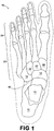
- FIGS. 1 and 2 There are twenty-six bones in the human foot 10, shown in FIGS. 1 and 2 .
- the five other tarsal bones are the navicular 16, the cuboid 18, and three cuneiforms 20, which form the middle of the foot.
- five metatarsals 22 form the lower portion of the instep of the foot.
- the metatarsals 22 radiate out to the phalanges 24, which are the toe bones.
- the talus 14 and the calcaneus 12 are the largest and are adjacent to each other. Also adjacent to the calcaneus 12 is the cuboid 18.
- the calcaneus 12 and the talus 14 define an articulating surface 40 between the two bones (the talo-calcaneal articulating surface), and the calcaneus 12 and the cuboid 18 also define an articulating surface 42 (the calcaneo-cuboid articulating surface).
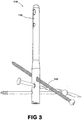
- Figures 3 and 3A each show a fusion assembly 110 according to embodiments of the invention.
- Assembly 110 features a nail 112 and fasteners 150.
- some fasteners 150 are shown as partially threaded and partially smooth or fully threaded.
- all fasteners 150 are shown having threads 152. In short, a surgeon may choose to use a combination of any type of fasteners.
- nail 112 is adapted to be implanted into a patient's tibial canal.
- the fasteners 150 are adapted to be inserted through and received by the nail 112 and secure to particular bones of the foot.
- Different nails 112 are typically provided for the left and right sides of a patient's body to account for differing angles.
- nail 112 has a distal portion 114 and a proximal portion 116.
- Nail 112 can be formed of Titanium, Titanium alloys, Surgical Steel alloys, or other desired material.
- Distal portion 114 is shown having a greater outer diameter relative to the proximal portion 116 and may be considered, if desired, also to include a frustoconical transition segment between the portion with the greater outer diameter and the smaller outer diameter. However, distal portion 114 need not necessarily have a greater outer diameter than other portions of the nail 112.
- Nail 112 can be also cannulated, if desired.
- One form of such cannulation is shown in Figs. 4 - 5 and can be accomplished by gundrilling or other appropriate techniques.
- Such cannulation enhances the ability of the nail 112 to be inserted using a closed surgical procedure, such as over a guide wire or rod.
- Cannulation in the distal portion 114 or portions of it can be of greater diameter than cannulation in the proximal portion 116 or portions of it, as desired.
- Instrument-receiving portion 120 may include any type of connecting portion, such as a threaded bore 119 (shown in Figure 5 ) that is adapted to receive and fasten to implantation instruments. Instrument-receiving portion 120 may also have an optional keyway 121 (shown in Figure 6 ) that can provide additional stabilization with respect to implantation instruments. Other options for connecting the instrument-receiving portion 120 to implantation instruments may be a ball and detent mechanism, a dovetail and slot configuration, a lock and key configuration, or any other stable locking mechanism.
- distal portion 114 of nail 112 may include one or more angled fastener holes 122, 130
- distal portion 114 may be provided with an outer diameter that is larger than the diameter at proximal portion 116.
- the greater outer diameter can in some ways be considered to provide favorable properties such as any or all of increased resistance to bending, rigidity, strength, stability, durability and enhanced reception and / or retention of fasteners.
- One feature of the present invention is that two or more fasteners are received by the nail, and one or more may be secured to it, as well as being secured to the patient's bone. See, e.g., Figure 3A .
- One structure used to accomplish the securing of the fastener to the nail can be a threaded bore and threaded fastener combination.
- the nail can have a threaded bore 128 and the fastener can have corresponding threads 152 at or near the portion received by the nail.
- the fastener is a threaded screw 150.
- Threads 152 may be provided in any number of shapes (e.g., trapezoidal teeth, triangular teeth, square teeth), pitches, and rotations (e.g., tightly wound around fastener or "loosely” wound such that there is a greater distance between each thread).
- the screw threads and the threads of the nail need not have the same shape, pitch, or rotation, although they typically will.
- the fastener is a partially threaded screw.
- the threads may be provided in any number of shapes, pitches, and rotations.
- the threads are preferably located at or near the portion where the threads are secured into nail to prevent their migration.
- the fastener has a series of cutting edges that engage a patient's bone.
- Cutting edges may be cutting blades, helical blades, spikes, or any other structure capable of holding and/or engaging bone. Cutting edges may cover all or just a portion of the fastener.
- the fastener may feature a bolt, a moly bolt, a tension spring, or any other structure capable of holding and/or engaging bone.
- the threaded bore 128 is adapted to receive and secure a corresponding structure on the fastener with respect to nail 112, as well as allow fastener to engage with bone.
- One or more openings in the nail 112 may be provided as threaded bores. It is also possible to provide a nail 112 having a combination of threaded and non-threaded bores (the non-threaded bore structure is described below). It is also possible to provide openings in the nail that are partially threaded and partially non-threaded.
- One optional feature that may be provided with assembly 110 is an insert or bushing (not shown) to prevent rotation of the fastener. See Smith & Nephew, US2005/0187550 filed November 30, 2004 and titled "Humeral Nail”.
- This feature may provide a function similar to fastener anchors that can be used to hang a picture on a wall, i.e., the insert interferes with the rotation of the fastener in the nail and can prevent it from wobbling or threading out, without interfering with the ability of the fastener to insert into the nail at a range of angles.
- the insert may be used in connection with a threaded or non-threaded bore. It may be secured with respect to nail by the threads, by a rib and locking ring configuration, by injecting a biologic or bone cement through the cannulation as each fastener is inserted, by an interference fit, or any other securing means.
- a further feature of some embodiments of the present invention is that fusion of the hindfoot can be established by connecting and stabilizing certain articulating surfaces of the foot.
- the talus 14 and the calcaneus 12 are connected to one another by a fastener that crosses the talo-calcaneal articulating surface when implanted.
- the cuboid 18 and the calcaneus 12 are connected to one another by a fastener that crosses the calcaneo-cuboid articulating surface when implanted. This may be done by specifically targeting these bones using an assembly 110 with angled holes or bores according to the present invention, as shown in Fig. 3A .
- This particular embodiment provides for multi-planar (and if desired, multi-axial) fixation.
- the nail may also be adapted to be secured to the tibia 30 for additional stability.
- the fasteners are pin-like or substantially smooth.
- the fasteners may have a portion that is threaded (or that contains cutting blades, helically shaped structures having any angle relative to the fastener axis, or other fastening structure to engage bone) that are adapted to secure to a patient's bone, and a portion that is at least partially smooth.
- These fasteners may be referred to as compression screws, an example of which is shown in Figure 3 .
- Compression screws have a portion adapted to attach to a patient's bone, as well as an at least partially smooth portion that articulates with the nail for sliding compression.
- the at least partially smooth surface is allowed to "slide" within the nail, such that when the patient applies pressure to the implant (for example, if the implant is a weight-bearing implant in the foot, the patient applies pressure when stepping down), the fastener compresses the bones together.
- the bone fragments are allowed to slide and bear on each other for better healing and fusion of the site.
- the portion that cooperates with a patient's bone is adapted to cooperate with the calcaneus, and in certain embodiments, the portion that cooperates with a patient's bone is adapted to cross one or more articulating surfaces of the foot.
- the angled fastener holes at least partially have internal threads 128.
- internal threads 128 of nail 112 cooperate with fastener threads 152 of fasteners 150 to secure the fasteners into the nail 112, as well as into the patient's bone.
- fasteners will be referred to as fasteners 150 (which are shown as threaded screws) throughout the remainder of this application, although it is understood that fasteners may take any of the above-described forms, such as compression screws, pins, partially threaded screws, and so forth. See e.g. Figure 3 .
- Fastener holes 122, 130 are provided at optimal angles that allow the surgeon to achieve fastener attachment into the calcaneus 12, the talus 14, and the cuboid 18.
- fastener holes 122, 130 are oriented so that fasteners 150 can be inserted into the nail 112 and cross one or more of the articulating surfaces 40 and 42 of the foot bones.
- At least one angled fastener hole 122 is positioned at an angle ⁇ that is between about 45° and about 135° off of the central longitudinal axis 124. (In other words, when a fastener is inserted through the hole 122, the fastener itself creates an axis 160 that forms an angle of between about 45° and about 135° with the central longitudinal axis 124, as shown in Figure 4A .)
- at least one angled fastener hole 122 is positioned at an angle between about 65° and about 115° off of the central longitudinal axis 124.
- the angled fastener hole 122 is positioned at an angle between about 80° and about 90° off of the central longitudinal axis 124, and most preferably, at about 85° off of the central longitudinal axis 124.
- Central longitudinal axis 124 also intersects a plurality of planes.
- One cross-section defined by central longitudinal axis 124 is central plane 125, which is the plane in the page of the paper. This cross-sectional view is shown in Figure 4A .
- angled fastener hole 122 may also be disposed at an angle that is rotated off of the plane 125 of the paper.
- fastener 150 may either be rotated about 0-45° into the plane 125 of the page or rotated about 0-45° out of the plane 125 of the page.
- angled fastener hole 122 is rotated about 2-30° off of plane 125. In a further embodiment, it is rotated about 5-15 ° off of plane 125, and is most preferably, about 10° off of plane 125. (This angle may be in either the medial or the lateral direction.)
- angled fastener hole 122 is adapted to receive a fastener that targets the cuboid 18 in use, or that at least partially traverses the calcaneo-cuboid articulating surface 42, as shown in Figure 3 .
- a second angled fastener hole 130 may also positioned on the distal portion 144 of nail 112. This angled fastener hole 130 may be positioned at an angle ⁇ that is between about 25° and about 135° off of the central longitudinal axis 124, such that a fastener inserted therein forms axis 162. In a particular embodiment, second angled fastener hole 130 is positioned at an angle between about 45° and about 115° off of the central longitudinal axis 124. In an even more preferred embodiment, second angled fastener hole 130 is positioned at an angle between about 50° and about 75° off of the central longitudinal axis 124, and most preferably, second angled fastener hole 130 is positioned at about 55° off of the central longitudinal axis 124.
- second angled fastener hole 130 may also be rotated at an angle off of plane 125.
- angled fastener hole 130 may be rotated about 0-45° off of plane 125, as shown in Figure 6 .
- angled fastener hole 130 is rotated about 2-30° off of plane 125. In a further embodiment, it is rotated about 5-15 ° off of plane 125, and is most preferably, about 10° off of plane 125. (Again, this angle may also be in either the medial or the lateral direction. It is preferred, although not required, that angled fastener hole 122 be about 10° in the opposite direction of angled fastener hole 130.)
- second angled fastener hole 130 is adapted to receive a fastener that targets the talus 14 in use, or that at least partially traverses the talo-calcaneal articulating surface 40, as shown in Figure 3 .
- FIG. 1 shows the nail of Figure 4 cut through a plane that extends perpendicular to plane 125 and then rotated 90° to illustrate the threaded bore of fastener hole 132.
- fastener hole 132 is disposed through distal portion 114 of nail 112 in the horizontal plane, give or take a few degrees.
- the fastener creates an axis that forms an angle of between about 80° - 100°, and preferably about 90° with the central longitudinal axis 124, as shown in Figure 3 .
- the third fastener hole 132 is a transverse fastener that targets the calcaneus 12.
- a surgeon may choose to use one or more of threaded holes 122, 130, 132, or any combination thereof. For example, a surgeon may only need to use hole 122. In other cases, for example, if more stability is needed, the surgeon will also use 130 and/or hole 132. Alternatively, a surgeon may only use hole 132, but again, may use additional holes for additional stability.
- Fasteners 150 may be provided in any number of lengths, although it is preferable that at least one fastener be provided in a length that allows it to cross one of more of articulating surfaces 40 and 42. Exemplary fastener lengths may be between 50 to 110 mm.
- openings 136, 137 are provided for rotational stability of assembly 110 and are typically not threaded or angled, although they can be angled and / or threaded as desired.
- openings 136, 137 are typically not threaded or angled, although they can be angled and / or threaded as desired.
- the surgeon may choose between static or dynamic locking by placing a fastener, pin, or small nail through either a static hole 136 or dynamic slot 137 and into the tibia 30. It is preferred that one of each opening 136, 137 be provided in order to give the surgeon the most flexibility, although this is not required.
- a surgeon first chooses the properly-sized nail 112. (Nails are typically provided in 10-50 cm lengths.) The choice is based on the length of the ankle from the bottom of the calcaneus to a suitable fixation point on the tibia. In essence, the goal is to fuse the nail 112 with the calcaneus 12 and the tibia 30 to immobilize the ankle joint. Typically, the surgeon will remove cartilage from the ankle to encourage the bones to fuse.
- the surgeon makes an incision into the non-weight bearing part of the sole of the foot (i.e., the fatty tissue part of the heel) in line with the tibial planar axis.
- the surgeon may insert a guide wire into the tibial canal to assist reaming and the placement of nail 112.
- the nail 112 is driven into the center (marrow) portion of the tibia 30, typically using one or more of the instrument-receiving portion 120 or the keyway 121 for securing the implant instrumentation.
- the surgeon uses a C-arm or other image intensifier to insert the nail 112 over a guide wire or rod in a closed surgical procedure as well as to insert the related fasteners.
- Instrumentation may also be used to hold and guide drill bits to prepare other bones for receiving fasteners. Similar instrumentation may be used to hold and place a fastener. The fastener can be rotated into place, hammered, or otherwise inserted as desired. In some instances, guide wires may be used to place the fastener as well.
- the surgeon plans to aid the fusion process by inserting a fastener that will cross the calcaneo-cuboid articulating surface 42, the surgeon will insert the fastener through the posterior aspect of the calcaneus, through the opening in the nail, and into the cuboid to target that junction.
- the surgeon would place fastener 150 into the most inferior angled fastener hole 122.
- the threads of fastener 150 cooperate with internal threads 128, as well as achieve purchase into the calcaneus 12 and cuboid 18.
- a compression screw, a pin, an at least partially threaded screw, or other embodiments may be used. In any event, this fastener will typically have a relatively "shallow" angle, being inserted at the calcaneus and at least partially crossing the calcaneo-cuboid articulating surface 42.
- the surgeon may gently tap the driving end 118 of the nail 112 to achieve compression of the ankle. If the surgeon plans to place a transverse fastener (in this case, a fastener that will cooperate with the calcaneus 12), the fastener may be inserted through third fastener hole 132 in either the medial to lateral or lateral to medial direction. Even though this fastener is not necessarily strictly horizontal, it tends to be the most horizontally-located of the fasteners.
- the surgeon plans to aid the fusion process by inserting a fastener that will cross the talo-calcaneal articulating surface 40, the surgeon will insert a fastener into the posterior of the calcaneus, through an opening of the nail, and into the talus to target that junction.
- the surgeon would place fastener 150 into the superior angled fastener hole 130.
- the threads of fastener 150 will cooperate with internal threads 128, as well as achieve purchase into the calcaneus 12 and talus 14.
- a compression screw, a pin, an at least partially threaded screw, or other embodiments may be used.
- this fastener tends to be the most steeply angled of the three (assuming that all three fasteners are used). Assuming the patient's foot is standing on a horizontal surface, this fastener will have a relatively steep "upward" angle to at least partially cross the talo-calcaneal articulating surface 40.
- the surgeon will secure the nail 112 with a fastener at the proximal portion 116 of the nail 112.
- the surgeon may choose between static or dynamic locking by placing the fastener through either a static hole 136 or a dynamic slot 137 in nail 112.
Landscapes
- Health & Medical Sciences (AREA)
- Orthopedic Medicine & Surgery (AREA)
- Surgery (AREA)
- Life Sciences & Earth Sciences (AREA)
- Heart & Thoracic Surgery (AREA)
- Nuclear Medicine, Radiotherapy & Molecular Imaging (AREA)
- Engineering & Computer Science (AREA)
- Biomedical Technology (AREA)
- Neurology (AREA)
- Medical Informatics (AREA)
- Molecular Biology (AREA)
- Animal Behavior & Ethology (AREA)
- General Health & Medical Sciences (AREA)
- Public Health (AREA)
- Veterinary Medicine (AREA)
- Prostheses (AREA)
- Surgical Instruments (AREA)
Description
- This application claims priority to
U.S. Patent Application Serial No. 11/061,699 entitled "Hindfoot Nail" filed February 18, 2005. - The invention relates to nail and fastener assemblies that provide stable fixation of the hindfoot.
- Serious ankle problems can be caused by a number of conditions, such as arthritis (e.g., osteoarthritis, rheumatoid arthritis), diabetes, trauma, accidents, or severe deformation. One solution is to replace the ankle joint with an implant or ankle prosthesis. However, prostheses often fail due to subsidence, wear, and loosening within a few years following implantation. There are also anatomical considerations that make such implants non-feasible in some cases. Poor results with prostheses have led many surgeons to abandon implant arthroplasty in more serious cases and return to ankle arthrodesis - fusing the joint to ultimately result in bone fusion. Often, by the time fusion is selected as the best option, there is minimal motion at the joint prior to surgery.
- Ankle fusion typically involves using screws and pins to hold the bone together. In a typical fusion surgery, the ankle joint is fused, allowing the tibia (shinbone) to grow together or fuse with the talus bone, the bone of the ankle that articulates with the tibia and fibula, and the calcaneus, the bone that forms the ankle joint. A long ankle arthrodesis "nail" may be inserted through the heel and fixed into place with screws or pins. Often, one or more screws or pins are inserted into the calcaneus, the bone at the lower back part of the foot forming the heel, which provides more stability.
- Many of the currently available ankle fusion systems are less than optimal. One reason is because the screws or pins used to fuse the foot bones are secured only into the foot bones themselves; they are not secured to the ankle arthrodesis nail through which they are received. In some instances, an unsecured screw or pin can dislodge itself from the patient's bone and migrate out over years of use. Thus, there is a need in the art to provide a better solution to reduce the risk of migration.
- Another reason that many of the currently available fusion systems are less than optimal is because they do not have angled fastener-receiving holes that allow for multiplanar fixation. Alternatively, if angled holes are present, they are not provided at optimal angle ranges for securing and immobilizing the ankle. In some commercially available systems, the center of the fastener-receiving hole opening(s) in the ankle arthrodesis nail is perpendicular to the longitudinal axis of the nail, such that when the fastener is inserted, it is also perpendicular to the nail. This does not allow the surgeon to achieve purchase into preferred bones of the foot, but instead, limits the surgeon to securing the fastener into the calcaneus (the heel bone). Such systems also fail to provide the option of inserting fasteners in multiple axes to provide a more stable fixation system.
- Moreover, fusion systems typically include one or more fasteners that engage only one foot bone in use. The fasteners do not cross articulating surfaces. It would be advantageous to provide a system that allows one or more fasteners to cross one or more articulating surfaces of the bones in the foot in order to provide more stability.
- Another disadvantage of some fusion systems is that they do not provide nails with reinforced distal portions. If the nail is the same diameter throughout its length, but there are fastener holes in the distal portion, the implant may be weaker at that portion due to increased stresses from the patient's weight. Thus, there is a need for a fusion system that provides greater rigidity and stability in use.
-
US6,579,293 describes an assembly for use in ankle arthrodesis which includes a vertical intramedullary rod and an oblique screw which passes through the rod. The preamble of claim 1 is based on the disclosure of this document. Accordingly, it would be advantageous to provide a nail and fastener assembly that addresses many of the problems that have not been solved by currently-available systems. - The present invention comprehends various embodiments of nail and fastener assemblies, which may be employed, among other things, for use in providing a stable construct for optimal fixation of the hindfoot. It also comprehends various methods for implanting the nail and fastener assemblies.
- Because bone quality is typically poor in patients who are candidates for this procedure, it is beneficial for a system to include a nail that provides additional fixation to hold the fasteners, which may be screws, pins, partially threaded screws, fasteners having a surface with threads or blades of various pitches, shapes, and rotations about the fastener, helical blades, bolts, or any other structure capable of holding and/or engaging bone, in a
fixed position. It is also beneficial for a system to provide the option of stabilizing various articulating surfaces of the foot. - Accordingly, certain embodiments of the present invention provide fusion systems with fixation features between the nail and fastener that secure the fastener into the nail. Other embodiments provide a fusion system with one or more openings of the nail that receive fasteners at various angles, allowing one or more fastener to cross one or more articulating surfaces of the foot to provide for multi-planar and multi-axial implantation of the fasteners. Certain structures provide a fusion system with a fastener that crosses one or more of the talo-calcaneal and the calcaneo-cuboid articulating surfaces. Other embodiments combine these features or aspects of them. The invention includes a hindfoot nail with a threaded fastener-receiving hole and angled fastener-receiving bores, and structures according to certain embodiments of the invention. The invention is an implant assembly for a hindfoot, comprising a hindfoot nail having a proximal portion, a distal portion, and a central longitudinal axis, and a fastener adapted to be received by the hindfoot nail; wherein the distal portion of the hindfoot nail comprises a fastener-receiving hole that is at least partially threaded. Also disclosed are methods for at least partially fusing certain bones of the patient's hindfoot.
- Certain devices of the present invention accomplish these results in a number of ways, some of which are discussed in detail below, with reference to the drawings.
-
-
FIG 1 shows a dorsal view of the anatomy of the foot. -
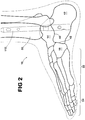
FIG. 2 shows a side view of a foot having an implanted nail according to one embodiment of the invention. -
FIG. 3 shows a perspective view of one embodiment of a nail and fastener assembly. -
FIG. 3A shows a perspective hind view of a foot having an implanted nail and fastener assembly according to another embodiment of the invention. -
FIG. 4 shows a side view of a nail according to one embodiment of the invention. -
FIG. 4A shows a cross-sectional view of the nail ofFigure 4 . -
FIG. 5 shows another cross-sectional view of the nail ofFigure 4 . -
FIG. 6 shows a cross-sectional schematic view of the threaded angled bores of the nail ofFigure 4 showing fasteners (in phantom) inserted. - There are twenty-six bones in the
human foot 10, shown inFIGS. 1 and2 . There are seven tarsal bones: the bone that forms the heel is thecalcaneus 12; thetalus 14 connects to and supports the tibia 30 (shown inFIG. 2 ) at the ankle. The five other tarsal bones are the navicular 16, thecuboid 18, and three cuneiforms 20, which form the middle of the foot. Next, fivemetatarsals 22 form the lower portion of the instep of the foot. Themetatarsals 22 radiate out to thephalanges 24, which are the toe bones. - Of the tarsal bones, the
talus 14 and thecalcaneus 12 are the largest and are adjacent to each other. Also adjacent to thecalcaneus 12 is the cuboid 18. Thecalcaneus 12 and thetalus 14 define an articulatingsurface 40 between the two bones (the talo-calcaneal articulating surface), and thecalcaneus 12 and the cuboid 18 also define an articulating surface 42 (the calcaneo-cuboid articulating surface). Some or all of these, or combinations of them, are the foot bones and articulating surfaces that can be of particular interest to certain embodiments of the present invention. -
Figures 3 and3A each show afusion assembly 110 according to embodiments of the invention.Assembly 110 features anail 112 andfasteners 150. InFigure 3 , somefasteners 150 are shown as partially threaded and partially smooth or fully threaded. InFigure 3A , allfasteners 150 are shown havingthreads 152. In short, a surgeon may choose to use a combination of any type of fasteners. - As shown in
Figure 2 ,nail 112 is adapted to be implanted into a patient's tibial canal. Thefasteners 150 are adapted to be inserted through and received by thenail 112 and secure to particular bones of the foot.Different nails 112 are typically provided for the left and right sides of a patient's body to account for differing angles. - As shown in
Figure 4 ,nail 112 has adistal portion 114 and aproximal portion 116.Nail 112, as is the case with other components of embodiments disclosed herein, can be formed of Titanium, Titanium alloys, Surgical Steel alloys, or other desired material.Distal portion 114 is shown having a greater outer diameter relative to theproximal portion 116 and may be considered, if desired, also to include a frustoconical transition segment between the portion with the greater outer diameter and the smaller outer diameter. However,distal portion 114 need not necessarily have a greater outer diameter than other portions of thenail 112. -
Nail 112 can be also cannulated, if desired. One form of such cannulation is shown inFigs. 4 - 5 and can be accomplished by gundrilling or other appropriate techniques. Such cannulation enhances the ability of thenail 112 to be inserted using a closed surgical procedure, such as over a guide wire or rod. Cannulation in thedistal portion 114 or portions of it, can be of greater diameter than cannulation in theproximal portion 116 or portions of it, as desired. - At the
distal portion 114 is adriving end 118 that has an instrument-receivingportion 120. Instrument-receivingportion 120 may include any type of connecting portion, such as a threaded bore 119 (shown inFigure 5 ) that is adapted to receive and fasten to implantation instruments. Instrument-receivingportion 120 may also have an optional keyway 121 (shown inFigure 6 ) that can provide additional stabilization with respect to implantation instruments. Other options for connecting the instrument-receivingportion 120 to implantation instruments may be a ball and detent mechanism, a dovetail and slot configuration, a lock and key configuration, or any other stable locking mechanism. - Because
distal portion 114 of nail 112 (which again may, if desired, contain some or all of the frustoconical transition shown inFigs. 4 - 5 ) may include one or more angled fastener holes 122, 130,distal portion 114 may be provided with an outer diameter that is larger than the diameter atproximal portion 116. In the particular embodiment shown inFigs. 4 - 5 , the greater outer diameter can in some ways be considered to provide favorable properties such as any or all of increased resistance to bending, rigidity, strength, stability, durability and enhanced reception and / or retention of fasteners. - One feature of the present invention is that two or more fasteners are received by the nail, and one or more may be secured to it, as well as being secured to the patient's bone. See, e.g.,
Figure 3A . One structure used to accomplish the securing of the fastener to the nail can be a threaded bore and threaded fastener combination. In this example, the nail can have a threadedbore 128 and the fastener can havecorresponding threads 152 at or near the portion received by the nail. - In the specific embodiment shown in
Figure 3A , the fastener is a threadedscrew 150.Threads 152 may be provided in any number of shapes (e.g., trapezoidal teeth, triangular teeth, square teeth), pitches, and rotations (e.g., tightly wound around fastener or "loosely" wound such that there is a greater distance between each thread). The screw threads and the threads of the nail need not have the same shape, pitch, or rotation, although they typically will. - In an alternate embodiment (not shown), the fastener is a partially threaded screw. Again, the threads may be provided in any number of shapes, pitches, and rotations. In this example, the threads are preferably located at or near the portion where the threads are secured into nail to prevent their migration.
- In a further embodiment, the fastener has a series of cutting edges that engage a patient's bone. Cutting edges may be cutting blades, helical blades, spikes, or any other structure capable of holding and/or engaging bone. Cutting edges may cover all or just a portion of the fastener. Alternatively, the fastener may feature a bolt, a moly bolt, a tension spring, or any other structure capable of holding and/or engaging bone.
- In use, the threaded
bore 128 is adapted to receive and secure a corresponding structure on the fastener with respect to nail 112, as well as allow fastener to engage with bone. One or more openings in thenail 112 may be provided as threaded bores. It is also possible to provide anail 112 having a combination of threaded and non-threaded bores (the non-threaded bore structure is described below). It is also possible to provide openings in the nail that are partially threaded and partially non-threaded. - One optional feature that may be provided with
assembly 110 is an insert or bushing (not shown) to prevent rotation of the fastener. SeeSmith & Nephew, US2005/0187550 filed November 30, 2004 and titled "Humeral Nail". This feature may provide a function similar to fastener anchors that can be used to hang a picture on a wall, i.e., the insert interferes with the rotation of the fastener in the nail and can prevent it from wobbling or threading out, without interfering with the ability of the fastener to insert into the nail at a range of angles. The insert may be used in connection with a threaded or non-threaded bore. It may be secured with respect to nail by the threads, by a rib and locking ring configuration, by injecting a biologic or bone cement through the cannulation as each fastener is inserted, by an interference fit, or any other securing means. - A further feature of some embodiments of the present invention is that fusion of the hindfoot can be established by connecting and stabilizing certain articulating surfaces of the foot. In one specific embodiment, the
talus 14 and the calcaneus 12 are connected to one another by a fastener that crosses the talo-calcaneal articulating surface when implanted. In another specific embodiment, the cuboid 18 and the calcaneus 12 are connected to one another by a fastener that crosses the calcaneo-cuboid articulating surface when implanted. This may be done by specifically targeting these bones using anassembly 110 with angled
holes or bores according to the present invention, as shown inFig. 3A . This particular embodiment provides for multi-planar (and if desired, multi-axial) fixation. The nail may also be adapted to be secured to thetibia 30 for additional stability. - One particularly beneficial aspect of providing angled fastener holes 122, 130 is that they are provided such that any fastener received therein can target specific bones. In one structure according to certain embodiments of the invention, the fasteners are pin-like or substantially smooth. In another structure, the fasteners may have a portion that is threaded (or that contains cutting blades, helically shaped structures having any angle relative to the fastener axis, or other fastening structure to engage bone) that are adapted to secure to a patient's bone, and a portion that is at least partially smooth. These fasteners may be referred to as compression screws, an example of which is shown in
Figure 3 . - Compression screws have a portion adapted to attach to a patient's bone, as well as an at least partially smooth portion that articulates with the nail for sliding compression. The at least partially smooth surface is allowed to "slide" within the nail, such that when the patient applies pressure to the implant (for example, if the implant is a weight-bearing implant in the foot, the patient applies pressure when stepping down), the fastener compresses the bones together. The bone fragments are allowed to slide and bear on each other for better healing and fusion of the site. The portion that cooperates with a patient's bone is adapted to cooperate with the calcaneus, and in certain embodiments, the portion that cooperates with a patient's bone is adapted to cross one or more articulating surfaces of the foot. The angled fastener holes at least partially have
internal threads 128. In use,internal threads 128 ofnail 112 cooperate withfastener threads 152 offasteners 150 to secure the fasteners into thenail 112, as well as into the patient's bone. For ease of reference, fasteners will be referred to as fasteners 150 (which are shown as threaded screws) throughout the remainder of this application, although it is understood that fasteners may take any of the above-described forms, such as compression screws, pins, partially threaded screws, and so forth. See e.g.Figure 3 . Fastener holes 122, 130 are provided at optimal angles that allow the surgeon to achieve fastener attachment into thecalcaneus 12, thetalus 14, and the cuboid 18. In embodiments in which the fastener is adapted to cross articulating surfaces, fastener holes 122, 130 are oriented so thatfasteners 150 can be inserted into thenail 112 and cross one or more of the articulatingsurfaces - For example, consider
nail 112 having a centrallongitudinal axis 124 as shown inFigures 4-5 . At least oneangled fastener hole 122 is positioned at an angle θ that is between about 45° and about 135° off of the centrallongitudinal axis 124. (In other words, when a fastener is inserted through thehole 122, the fastener itself creates anaxis 160 that forms an angle of between about 45° and about 135° with the centrallongitudinal axis 124, as shown inFigure 4A .) In a particular embodiment, at least oneangled fastener hole 122 is positioned at an angle between about 65° and about 115° off of the centrallongitudinal axis 124. In an even more preferred embodiment, theangled fastener hole 122 is positioned at an angle between about 80° and about 90° off of the centrallongitudinal axis 124, and most preferably, at about 85° off of the centrallongitudinal axis 124. - Central
longitudinal axis 124 also intersects a plurality of planes. One cross-section defined by centrallongitudinal axis 124 iscentral plane 125, which is the plane in the page of the paper. This cross-sectional view is shown inFigure 4A . In addition to its angled orientation with respect to centrallongitudinal axis 124,angled fastener hole 122 may also be disposed at an angle that is rotated off of theplane 125 of the paper. (In other words, when a fastener is inserted throughhole 122, the fastener forms a second plane that is not aligned withplane 125 and would either extend from or retreat intoplane 125 of the paper.) In one embodiment,fastener 150 may either be rotated about 0-45° into theplane 125 of the page or rotated about 0-45° out of theplane 125 of the page. In one embodiment,angled fastener hole 122 is rotated about 2-30° off ofplane 125. In a further embodiment, it is rotated about 5-15 ° off ofplane 125, and is most preferably, about 10° off ofplane 125. (This angle may be in either the medial or the lateral direction.) - In certain embodiments, angled
fastener hole 122 is adapted to receive a fastener that targets the cuboid 18 in use, or that at least partially traverses the calcaneo-cuboid articulating surface 42, as shown inFigure 3 . - A second
angled fastener hole 130 may also positioned on the distal portion 144 ofnail 112. Thisangled fastener hole 130 may be positioned at an angle α that is between about 25° and about 135° off of the centrallongitudinal axis 124, such that a fastener inserted therein formsaxis 162. In a particular embodiment, secondangled fastener hole 130 is positioned at an angle between about 45° and about 115° off of the centrallongitudinal axis 124. In an even more preferred embodiment, secondangled fastener hole 130 is positioned at an angle between about 50° and about 75° off of the centrallongitudinal axis 124, and most preferably, secondangled fastener hole 130 is positioned at about 55° off of the centrallongitudinal axis 124. - In addition to its angled orientation with respect to central
longitudinal axis 124, secondangled fastener hole 130 may also be rotated at an angle off ofplane 125. For example,angled fastener hole 130 may be rotated about 0-45° off ofplane 125, as shown inFigure 6 . In one embodiment,angled fastener hole 130 is rotated about 2-30° off ofplane 125. In a further embodiment, it is rotated about 5-15 ° off ofplane 125, and is most preferably, about 10° off ofplane 125. (Again, this angle may also be in either the medial or the lateral direction. It is preferred, although not required, that angledfastener hole 122 be about 10° in the opposite direction ofangled fastener hole 130.) - In certain embodiments, second
angled fastener hole 130 is adapted to receive a fastener that targets thetalus 14 in use, or that at least partially traverses the talo-calcaneal articulating surface 40, as shown inFigure 3 . - There is provided a
third fastener hole 132, which also hasinternal threads 128. Considernail 112 with ahorizontal axis 127 that is perpendicular to the centrallongitudinal axis 124 and that defines a horizontal plane perpendicular to plane 125 (i.e., extending out from the page).Figure 5 shows the nail ofFigure 4 cut through a plane that extends perpendicular to plane 125 and then rotated 90° to illustrate the threaded bore offastener hole 132. - In one embodiment,
fastener hole 132 is disposed throughdistal portion 114 ofnail 112 in the horizontal plane, give or take a few degrees. Whenfastener 150 is inserted throughfastener hole 132, the fastener creates an axis that forms an angle of between about 80° - 100°, and preferably about 90° with the centrallongitudinal axis 124, as shown inFigure 3 . In certain embodiments, thethird fastener hole 132 is a transverse fastener that targets thecalcaneus 12. - In use, a surgeon may choose to use one or more of threaded
holes hole 122. In other cases, for example, if more stability is needed, the surgeon will also use 130 and/orhole 132. Alternatively, a surgeon may only usehole 132, but again, may use additional holes for additional stability. -
Fasteners 150 may be provided in any number of lengths, although it is preferable that at least one fastener be provided in a length that allows it to cross one of more of articulatingsurfaces - There may also be one or more static locking
holes 136 or adynamic compression slots 137 at theproximal portion 116 ofnail 112. Theseopenings assembly 110 and are typically not threaded or angled, although they can be angled and / or threaded as desired. Although the present inventors believe that it would not be good surgical practice to fix the fasteners to the holes in the proximal portion ofnail 112 by threads because thenail 112 should not be overconstrained, it is understood that there could be instances when such fixation would be desired, and threaded upper holes are considered within the scope of this invention. - The surgeon may choose between static or dynamic locking by placing a fastener, pin, or small nail through either a
static hole 136 ordynamic slot 137 and into thetibia 30. It is preferred that one of eachopening - A surgeon first chooses the properly-
sized nail 112. (Nails are typically provided in 10-50 cm lengths.) The choice is based on the length of the ankle from the bottom of the calcaneus to a suitable fixation point on the tibia. In essence, the goal is to fuse thenail 112 with thecalcaneus 12 and thetibia 30 to immobilize the ankle joint. Typically, the surgeon will remove cartilage from the ankle to encourage the bones to fuse. - Although the surgery may be performed as a closed procedure (i.e., minimally invasive) and it is often preferable for it to be that way due to ease of healing, some surgeons may also wish to remove cartilage from between the bones prior to the procedure, which is often performed using open surgical techniques. In short, embodiments of the invention lend themselves to use during ether type of procedure.
- In one embodiment of the procedure, the surgeon makes an incision into the non-weight bearing part of the sole of the foot (i.e., the fatty tissue part of the heel) in line with the tibial planar axis. The surgeon may insert a guide wire into the tibial canal to assist reaming and the placement of
nail 112. Once the canal has been reamed to an appropriate diameter and depth, thenail 112 is driven into the center (marrow) portion of thetibia 30, typically using one or more of the instrument-receivingportion 120 or thekeyway 121 for securing the implant instrumentation. Preferably, the surgeon uses a C-arm or other image intensifier to insert thenail 112 over a guide wire or rod in a closed surgical procedure as well as to insert the related fasteners. - Instrumentation may also be used to hold and guide drill bits to prepare other bones for receiving fasteners. Similar instrumentation may be used to hold and place a fastener. The fastener can be rotated into place, hammered, or otherwise inserted as desired. In some instances, guide wires may be used to place the fastener as well.
- If the surgeon plans to aid the fusion process by inserting a fastener that will cross the calcaneo-
cuboid articulating surface 42, the surgeon will insert the fastener through the posterior aspect of the calcaneus, through the opening in the nail, and into the cuboid to target that junction. In the embodiment shown, the surgeon would placefastener 150 into the most inferiorangled fastener hole 122. The threads offastener 150 cooperate withinternal threads 128, as well as achieve purchase into thecalcaneus 12 andcuboid 18. Alternatively, a compression screw, a pin, an at least partially threaded screw, or other embodiments may be used. In any event, this fastener will typically have a relatively "shallow" angle, being inserted at the calcaneus and at least partially crossing the calcaneo-cuboid articulating surface 42. - Once the first fastener is inserted, the surgeon may gently tap the driving
end 118 of thenail 112 to achieve compression of the ankle. If the surgeon plans to place a transverse fastener (in this case, a fastener that will cooperate with the calcaneus 12), the fastener may be inserted throughthird fastener hole 132 in either the medial to lateral or lateral to medial direction. Even though this fastener is not necessarily strictly horizontal, it tends to be the most horizontally-located of the fasteners. - Next, if the surgeon plans to aid the fusion process by inserting a fastener that will cross the talo-
calcaneal articulating surface 40, the surgeon will insert a fastener into the posterior of the calcaneus, through an opening of the nail, and into the talus to target that junction. In the embodiment shown, the surgeon would placefastener 150 into the superiorangled fastener hole 130. The threads offastener 150 will cooperate withinternal threads 128, as well as achieve purchase into thecalcaneus 12 andtalus 14. Alternatively, a compression screw, a pin, an at least partially threaded screw, or other embodiments may be used. In any event, this fastener tends to be the most steeply angled of the three (assuming that all three fasteners are used). Assuming the patient's foot is standing on a horizontal surface, this fastener will have a relatively steep "upward" angle to at least partially cross the talo-calcaneal articulating surface 40. - This procedure has been described as if the surgeon is using three fasteners, although it should be understood that a surgeon may choose to use fewer or more fasteners and that nails according to structures of this invention may also have more than three fastener-receiving bores.
- After the nail and junction fasteners have been properly placed in the patient's foot, the surgeon will secure the
nail 112 with a fastener at theproximal portion 116 of thenail 112. The surgeon may choose between static or dynamic locking by placing the fastener through either astatic hole 136 or adynamic slot 137 innail 112.
Claims (12)
- An implant assembly (110) for a hindfoot, comprising:a nail (112), the nail comprising a proximal portion (116), a distal portion (114), and a central longitudinal axis (124), the distal portion of the nail having at least a first angled, at least partially threaded fastener-receiving hole (122) and a second angled, at least partially threaded fastener-receiving hole (130), each having an axis (160, 162) which is at an angle with respect to the central axis; wherein the nail comprises a third fastener-receiving hole (132) which is at least partially threaded and which has an axis (127) that is substantially perpendicular to the central longitudinal axis;and wherein the assembly further comprises first and second fasteners (150); characterised in thatthe first fastener is adapted to be received by the nail and achieve at least partial purchase into a patient's calcaneus (12) and cuboid (18) bones and the second fastener is adapted to be received by the nail and achieve at least partial purchase into a patient's calcaneus and talus (14) bones.
- The implant assembly according to claim 1, wherein the fasteners have corresponding structures adapted to be received in the at least partially threaded fastener-receiving holes.
- The implant assembly of claim 1, wherein the axes of the first angled at least partially threaded fastener-receiving hole and the second angled at least partially threaded fastener-receiving hole are each provided at an angle between about 45° and about 135° with respect to the central longitudinal axis.
- The implant assembly of claim 1, wherein the axis of the first angled at least partially threaded fastener- receiving hole is provided at an angle between about 80° and about 90° with respect to the central longitudinal axis.
- The implant assembly of claim 1, wherein the axis of the second angled at least partially threaded fastener- receiving hole is provided at an angle between about 50° and about 75° with respect to the central longitudinal axis.
- The implant assembly of claim 1, wherein the axes of the at least first and second angled at least partially threaded fastener-receiving holes are disposed in different planes such that the assembly is adapted to provide multi-planar fixation.
- The implant assembly of claim 1, wherein the first angled at least partially threaded fastener-receiving hole is disposed at an angle between about 65° and 115° with respect to the central longitudinal axis; wherein the second angled at least partially threaded fastener-receiving hole is disposed at an angle between about 45° and 135° with respect to the central longitudinal axis; and wherein one of the first or the second fasteners is adapted to be received in one of the first or the second angled at least partially threaded fastener-receiving holes.
- The implant assembly of claim 7, wherein the central longitudinal axis of the nail and the axis of the first angled at least partially threaded fastener-receiving hole define a first plane, and the central longitudinal axis of the nail and the axis of the second angled at least partially threaded fastener-receiving hole define a second plane, and wherein the first and second planes are angled at about 2-30° to each other.
- The implant assembly of claim 1, further comprising the third fastener-receiving hole disposed at an angle of about 80-100° with respect to the central longitudinal axis.
- The implant assembly of claim 1, wherein the distal portion and the proximal portion each have a diameter, with the distal portion diameter being larger than the proximal portion diameter.
- The implant assembly of claim 1, further comprising one or more of a static locking hole (130) and a dynamic compression slot (136) at the proximal portion of the nail.
- The implant assembly of any preceding claim, wherein the assembly is adapted for use in stabilizing a patient's hindfoot by at least partially traversing the patient's calcaneo-cuboid and talo-calcaneal articulating surfaces.
Applications Claiming Priority (2)
| Application Number | Priority Date | Filing Date | Title |
|---|---|---|---|
| US11/061,699 US7410488B2 (en) | 2005-02-18 | 2005-02-18 | Hindfoot nail |
| PCT/US2006/005396 WO2006091460A1 (en) | 2005-02-18 | 2006-02-16 | Hindfoot nail |
Publications (2)
| Publication Number | Publication Date |
|---|---|
| EP1848355A1 EP1848355A1 (en) | 2007-10-31 |
| EP1848355B1 true EP1848355B1 (en) | 2018-01-10 |
Family
ID=36579552
Family Applications (1)
| Application Number | Title | Priority Date | Filing Date |
|---|---|---|---|
| EP06735179.1A Expired - Lifetime EP1848355B1 (en) | 2005-02-18 | 2006-02-16 | Hindfoot nail |
Country Status (6)
| Country | Link |
|---|---|
| US (4) | US7410488B2 (en) |
| EP (1) | EP1848355B1 (en) |
| JP (1) | JP2008529732A (en) |
| AU (1) | AU2006216878A1 (en) |
| CA (1) | CA2598014A1 (en) |
| WO (1) | WO2006091460A1 (en) |
Cited By (2)
| Publication number | Priority date | Publication date | Assignee | Title |
|---|---|---|---|---|
| US10610368B2 (en) | 2018-05-26 | 2020-04-07 | Acumed Llc | Ankle fusion system with expandable spacer |
| WO2021185971A1 (en) | 2020-03-18 | 2021-09-23 | Orthofix S.R.L. | Improved arthrodesis device |
Families Citing this family (77)
| Publication number | Priority date | Publication date | Assignee | Title |
|---|---|---|---|---|
| US8496712B2 (en) | 1999-10-22 | 2013-07-30 | Inbone Technologies, Inc. | Systems and methods for installing ankle replacement prostheses |
| CA2495110C (en) | 2002-08-10 | 2008-11-18 | H. Simon William | Method and apparatus for repairing the mid-foot region via an intramedullary nail |
| DE20213166U1 (en) * | 2002-08-28 | 2004-01-08 | Stryker Trauma Gmbh | humeral |
| CA2601090C (en) | 2005-03-14 | 2013-08-20 | Inbone Technologies, Inc. | Ankle replacement system |
| FR2885513B1 (en) * | 2005-05-13 | 2007-08-10 | Newdeal S A S Soc Par Actions | ARTHRODESIS APPARATUS FOR ARTICULATION, OF THE GENUS ARTICULATION OF THE ANKLE, AND NAIL OF ATHRODESE FOR USE IN SUCH AN APPARATUS |
| ES2447033T3 (en) * | 2006-04-06 | 2014-03-11 | Halifax Biomedical Inc. | Intramedullary stem with vent |
| US8075634B2 (en) * | 2006-04-11 | 2011-12-13 | Eli Hurowitz | Orthopedic device |
| BRPI0711349A2 (en) * | 2006-05-09 | 2011-08-30 | Synthes Gmbh | olecranon osteotomy fixation system |
| DE602006008439D1 (en) * | 2006-05-24 | 2009-09-24 | Munoz Felipe Lopez-Oliva | Device with a locking nail for the treatment of calcaneus fractures |
| US9320551B2 (en) * | 2007-01-26 | 2016-04-26 | Biomet Manufacturing, Llc | Lockable intramedullary fixation device |
| US9308031B2 (en) | 2007-01-26 | 2016-04-12 | Biomet Manufacturing, Llc | Lockable intramedullary fixation device |
| US8303590B2 (en) * | 2007-01-26 | 2012-11-06 | Ebi, Llc | Lockable intramedullary fixation device |
| US8157802B2 (en) * | 2007-01-26 | 2012-04-17 | Ebi, Llc | Intramedullary implant with locking and compression devices |
| US20080287949A1 (en) * | 2007-05-15 | 2008-11-20 | Zimmer, Inc. | Method and apparatus for securing a bone screw to an intramedullary nail |
| EP2219537B1 (en) * | 2007-10-16 | 2016-05-04 | Biomet Manufacturing, LLC | Apparatus for orthopedic fixation |
| JP5444242B2 (en) * | 2007-11-26 | 2014-03-19 | ビーダーマン・テクノロジーズ・ゲゼルシャフト・ミット・ベシュレンクテル・ハフツング・ウント・コンパニー・コマンディートゲゼルシャフト | Sputum intramedullary nail |
| US8771283B2 (en) | 2007-12-17 | 2014-07-08 | Wright Medical Technology, Inc. | Guide assembly for intramedullary fixation and method of using the same |
| JP2011519658A (en) | 2008-05-07 | 2011-07-14 | トゥルニエ | Humeral nail |
| US9017329B2 (en) * | 2008-06-24 | 2015-04-28 | Extremity Medical, Llc | Intramedullary fixation assembly and method of use |
| US8313487B2 (en) * | 2008-06-24 | 2012-11-20 | Extremity Medical Llc | Fixation system, an intramedullary fixation assembly and method of use |
| US8343199B2 (en) | 2008-06-24 | 2013-01-01 | Extremity Medical, Llc | Intramedullary fixation screw, a fixation system, and method of fixation of the subtalar joint |
| US8303589B2 (en) | 2008-06-24 | 2012-11-06 | Extremity Medical Llc | Fixation system, an intramedullary fixation assembly and method of use |
| US9289220B2 (en) | 2008-06-24 | 2016-03-22 | Extremity Medical Llc | Intramedullary fixation assembly and method of use |
| US8328806B2 (en) | 2008-06-24 | 2012-12-11 | Extremity Medical, Llc | Fixation system, an intramedullary fixation assembly and method of use |
| US9044282B2 (en) | 2008-06-24 | 2015-06-02 | Extremity Medical Llc | Intraosseous intramedullary fixation assembly and method of use |
| US20100121325A1 (en) * | 2008-06-24 | 2010-05-13 | Jeff Tyber | Hybrid intramedullary fixation assembly and method of use |
| US8540715B2 (en) * | 2008-11-10 | 2013-09-24 | Temple University—Of the Commonwealth System of Higher Education | Locking rod fusion device |
| CH701107B1 (en) * | 2009-05-18 | 2013-11-29 | Biedermann Technologies Gmbh | Apparatus for drilling an arcuate bore. |
| US8066775B2 (en) * | 2009-06-12 | 2011-11-29 | Branovacki George | Joint implant |
| WO2011008739A2 (en) * | 2009-07-14 | 2011-01-20 | Medicinelodge, Inc. Dba Imds Co-Innovation | Joint arthrodesis and arthroplasty |
| US9066757B2 (en) * | 2009-08-10 | 2015-06-30 | Virak Orthopedic Research Llc | Orthopedic external fixator and method of use |
| CA2783553C (en) | 2009-12-11 | 2017-10-17 | Small Bone Innovations, Inc. | Ankle fusion device, instrumentation and methods |
| US20120109217A1 (en) * | 2010-05-06 | 2012-05-03 | Christophe Perineau | Anterior-to-posterior talus-calcaneus screw insertion for ankle arthrodesis nail |
| US8876821B2 (en) | 2010-11-24 | 2014-11-04 | Kyle Kinmon | Intramedullary nail, system, and method with dynamic compression |
| FR2967890B1 (en) * | 2010-11-25 | 2013-12-20 | Mario Goldzak | OSTEOSYNTHESIS NAIL |
| EP2667808B1 (en) | 2011-01-26 | 2015-08-26 | Del Palma Orthopedics, LLC | Lower extremity fusion devices |
| CA2826703C (en) * | 2011-02-14 | 2019-06-25 | DePuy Synthes Products, Inc. | Intramedullary nail having self-retaining compression slot |
| US20120245701A1 (en) * | 2011-03-24 | 2012-09-27 | Rudolf Zak | Hemi Ankle Implant |
| ES2578295T3 (en) | 2012-11-14 | 2016-07-22 | Biedermann Technologies Gmbh & Co. Kg | Heel bone nail |
| EP3016604B1 (en) * | 2013-07-02 | 2018-10-10 | Cmarr Enterprises | Curved tibiotalar fusion nail |
| US9132018B1 (en) * | 2013-08-27 | 2015-09-15 | Mohammed A. Hajianpour | Total ankle replacement |
| US20170042591A9 (en) * | 2013-12-12 | 2017-02-16 | Extremity Designs, Llc | Intramedullary anchor-screw fracture fixation |
| US10045803B2 (en) | 2014-07-03 | 2018-08-14 | Mayo Foundation For Medical Education And Research | Sacroiliac joint fusion screw and method |
| US10188573B2 (en) | 2014-11-05 | 2019-01-29 | Allen Medical Systems, Inc. | Boot stirrup |
| US20220151664A1 (en) * | 2015-04-16 | 2022-05-19 | Texas Tech University System | Ankle (Tibio-Talar) Fusion Nail |
| CA2986752A1 (en) | 2015-05-22 | 2016-12-01 | Ebm Fusion Solutions, Llc | Joint or segmental bone implant for deformity correction |
| CN106388922A (en) * | 2015-07-28 | 2017-02-15 | 深圳市众恒德科技开发有限公司 | Calcaneal intramedullary fixation system and auxiliary placement instruments |
| US10307190B2 (en) * | 2016-04-15 | 2019-06-04 | Arthrex, Inc. | Arthrodesis devices for generating and applying compression within joints |
| US10751071B2 (en) | 2016-04-25 | 2020-08-25 | Imds Llc | Joint fusion instrumentation and methods |
| US10413332B2 (en) | 2016-04-25 | 2019-09-17 | Imds Llc | Joint fusion implant and methods |
| CN105997219B (en) * | 2016-06-30 | 2018-06-22 | 王永清 | Lock multidirectional intramedullary nail with lock |
| US10136998B2 (en) | 2016-08-30 | 2018-11-27 | Wright Medical Technology, Inc. | Revision total ankle implants |
| US10299847B2 (en) * | 2016-09-22 | 2019-05-28 | Globus Medical, Inc. | Systems and methods for intramedullary nail implantation |
| US11083503B2 (en) | 2016-09-22 | 2021-08-10 | Globus Medical, Inc. | Systems and methods for intramedullary nail implantation |
| US10492803B2 (en) | 2016-09-22 | 2019-12-03 | Globus Medical, Inc. | Systems and methods for intramedullary nail implantation |
| WO2018132764A1 (en) * | 2017-01-12 | 2018-07-19 | Dt Medtech, Llc | Internal ankle fixation and stabilization systems, foot securement and jig devices, and related methods |
| CA3057600C (en) * | 2017-06-13 | 2021-12-28 | Wright Medical Technology, Inc. | Calcaneal prosthesis |
| MX2020003481A (en) | 2017-10-11 | 2020-12-07 | Howmedica Osteonics Corp | Humeral fixation plate guides. |
| EP3740145B1 (en) | 2018-01-15 | 2025-06-04 | GLW, Inc. | Hybrid intramedullary rods |
| FR3077476B1 (en) * | 2018-02-07 | 2022-10-21 | In2Bones | IMPROVED ARTHRODESIS DEVICE |
| RU2689031C1 (en) * | 2018-03-19 | 2019-05-23 | федеральное государственное бюджетное учреждение "Российский научный центр "Восстановительная травматология и ортопедия" имени академика Г.А. Илизарова" Министерства здравоохранения Российской Федерации ФГБУ "РНЦ "ВТО" им. акад. Г.А. Илизарова" Минздрава России | Arthrodesis method of anterior talocacaneal articulation in children with cerebral paralysis |
| US10912652B2 (en) | 2018-07-09 | 2021-02-09 | Arthrex, Inc. | Arthroplasty implant systems for generating and applying dynamic compression |
| EP3626184A1 (en) * | 2018-09-21 | 2020-03-25 | OrthoXel DAC | A femoral nail system |
| US11000327B2 (en) | 2018-12-14 | 2021-05-11 | Nextremity Solutions, Inc. | Bone defect repair apparatus and method |
| US10987146B2 (en) | 2019-03-05 | 2021-04-27 | Nextremity Solutions, Inc. | Bone defect repair apparatus and method |
| US11633219B2 (en) | 2019-06-26 | 2023-04-25 | Globus Medical, Inc. | Fenestrated pedicle nail |
| CN111529139A (en) * | 2020-05-14 | 2020-08-14 | 北京大学人民医院 | A modular tumor-type artificial tibiotalar joint prosthesis |
| AU2021278357B2 (en) * | 2020-05-29 | 2026-04-16 | Stryker European Operations Limited | Funnel hole for intramedullary nail |
| CN113796938B (en) * | 2020-06-11 | 2025-02-18 | 上海市浦东新区人民医院 | Intramedullary nail guiding device |
| US20230270452A1 (en) * | 2020-06-29 | 2023-08-31 | University Of Kentucky Research Foundation | Method of Fusing a Tibiotalar Joint and Fused Tibiotalar Joint |
| TR202017292A1 (en) * | 2020-10-30 | 2022-05-23 | Tst Rakor Ve Tibbi Aletler Sanayi Ve Ticaret Ltd Sirketi | ARTRODESIA NAIL |
| US11291488B1 (en) | 2021-02-24 | 2022-04-05 | Medshape, Inc. | Dynamic compression devices and processes for making and using same |
| US12527669B2 (en) | 2021-03-04 | 2026-01-20 | Wright Medical Technology, Inc. | Multiaxial modular tibia stems |
| US20220304730A1 (en) * | 2021-03-26 | 2022-09-29 | Nuvasive Specialized Orthopedics, Inc. | Intramedullary device for ankle fusion |
| US12527606B1 (en) * | 2021-08-26 | 2026-01-20 | Medshape, Inc. | System and method for bone fixation based on bone quality |
| WO2023183617A1 (en) * | 2022-03-24 | 2023-09-28 | Mcginley Engineered Solutions, Llc | Ankle arthrodesis using retrograde hindfoot nail |
| US20250241691A1 (en) * | 2022-05-20 | 2025-07-31 | Smith & Nephew, Inc. | Intramedullary tibial nail with variable angle screw openings |
Family Cites Families (186)
| Publication number | Priority date | Publication date | Assignee | Title |
|---|---|---|---|---|
| US2136471A (en) | 1937-06-30 | 1938-11-15 | Rudolph H Schneider | Bone pin |
| US2987062A (en) * | 1956-07-23 | 1961-06-06 | Arthur E Ellison | Bone splint with absorbable section |
| US2952254A (en) | 1958-11-06 | 1960-09-13 | George J Keating | Fastener |
| US3739773A (en) * | 1963-10-31 | 1973-06-19 | American Cyanamid Co | Polyglycolic acid prosthetic devices |
| US3463158A (en) | 1963-10-31 | 1969-08-26 | American Cyanamid Co | Polyglycolic acid prosthetic devices |
| US3531561A (en) | 1965-04-20 | 1970-09-29 | Ethicon Inc | Suture preparation |
| US3272204A (en) | 1965-09-22 | 1966-09-13 | Ethicon Inc | Absorbable collagen prosthetic implant with non-absorbable reinforcing strands |
| DE1949923U (en) | 1966-09-29 | 1966-11-17 | Stahl Schanz Frankfurt Am Main | DOOR FRAME. |
| US3596656A (en) | 1969-01-21 | 1971-08-03 | Bernd B Kaute | Fracture fixation device |
| BE758156R (en) * | 1970-05-13 | 1971-04-28 | Ethicon Inc | ABSORBABLE SUTURE ELEMENT AND ITS |
| US3876068A (en) * | 1973-08-08 | 1975-04-08 | American Cyanamid Co | Suture reel-label package |
| US3960151A (en) * | 1973-11-09 | 1976-06-01 | Hemotec, Inc. | Method and means for the repair of peripheral nerves |
| US3902497A (en) | 1974-03-25 | 1975-09-02 | American Cyanamid Co | Body absorbable sponge and method of making |
| US3937223A (en) * | 1974-04-19 | 1976-02-10 | American Cyanamid Company | Compacted surgical hemostatic felt |
| US3892649A (en) * | 1974-05-13 | 1975-07-01 | Us Navy | Electrodeposition of bone within a plastic matrix |
| US3918100A (en) | 1974-05-13 | 1975-11-11 | Us Navy | Sputtering of bone on prostheses |
| JPS5839533B2 (en) * | 1975-12-30 | 1983-08-30 | 住友化学工業株式会社 | Implant noseizouhouhou |
| US4186448A (en) * | 1976-04-16 | 1980-02-05 | Brekke John H | Device and method for treating and healing a newly created bone void |
| AT352867B (en) * | 1976-05-12 | 1979-10-10 | Battelle Institut E V | BONE REPLACEMENT, BONE COMPOUND OR PROSTHESIS ANCHORING MATERIAL AND PROCESS FOR ITS PRODUCTION |
| CH613858A5 (en) | 1977-04-22 | 1979-10-31 | Straumann Inst Ag | |
| US4135507A (en) * | 1977-05-20 | 1979-01-23 | Harris Leslie J | Condylocephalic nail for fixation of pertrochanteric fractures |
| US4191185A (en) * | 1977-09-06 | 1980-03-04 | Johnson & Johnson | Catheter assembly |
| FR2439003A1 (en) * | 1978-10-20 | 1980-05-16 | Anvar | NEW OSTEOSYNTHESIS PARTS, THEIR PREPARATION AND THEIR APPLICATION |
| US4281420A (en) * | 1979-02-15 | 1981-08-04 | Raab S | Bone connective prostheses adapted to maximize strength and durability of prostheses-bone cement interface; and methods of forming same |
| US4292694A (en) | 1980-06-25 | 1981-10-06 | Lord Corporation | Prosthesis anchoring means |
| IT1132843B (en) * | 1980-09-15 | 1986-07-09 | Cise Spa | PLATE FOR JOINTS OF SEPARATE BONE PORTIONS FROM FRACTURE |
| US4338926A (en) * | 1980-11-21 | 1982-07-13 | Howmedica, Inc. | Bone fracture prosthesis with controlled stiffness |
| AT369637B (en) * | 1981-01-12 | 1983-01-25 | Plansee Metallwerk | PROFILED INTRAMEDULAR LOWER LEG |
| US4503847A (en) * | 1982-01-15 | 1985-03-12 | Howmedica, Inc. | Prosthetic nail |
| US4457301A (en) * | 1982-06-18 | 1984-07-03 | Howmedica Inc. | Intramedullary fixation device |
| US4989186A (en) * | 1982-08-16 | 1991-01-29 | The United States Of America As Represented By The Secretary Of The Navy | Target tracking sonar with false target detector |
| US4523591A (en) * | 1982-10-22 | 1985-06-18 | Kaplan Donald S | Polymers for injection molding of absorbable surgical devices |
| US4550449A (en) | 1982-11-08 | 1985-11-05 | Johnson & Johnson Products Inc. | Absorbable bone fixation device |
| US4475545A (en) | 1982-12-06 | 1984-10-09 | Ender Hans G | Bone-nail |
| US4465065A (en) | 1983-01-07 | 1984-08-14 | Yechiel Gotfried | Surgical device for connection of fractured bones |
| US4976258A (en) | 1983-03-09 | 1990-12-11 | Howmedica International, Inc. | Locking nail |
| DE3329449A1 (en) * | 1983-08-16 | 1985-03-07 | Biotest-Serum-Institut Gmbh, 6000 Frankfurt | MONOCLONAL ANTIBODY DETECTING A STRUCTURE COMMON TO HUMAN INTERLEUKIN-2 (TCGF) AND LIGHT CHAIN (LAMBDA) OF HUMAN IMMUNE LOBULIN, AND HYBRIDOMA CELL LINES THAT MAKE THESE MONOCLONAL |
| FI69402C (en) * | 1983-09-20 | 1986-02-10 | Materials Consultants Oy | OSTEOSYNTESANORDNING |
| US5190546A (en) * | 1983-10-14 | 1993-03-02 | Raychem Corporation | Medical devices incorporating SIM alloy elements |
| US4612923A (en) | 1983-12-01 | 1986-09-23 | Ethicon, Inc. | Glass-filled, absorbable surgical devices |
| CH668173A5 (en) | 1984-05-14 | 1988-12-15 | Synthes Ag | DEVICE FOR FIXING TUBE BONE FRACTURES WITH A BONE MARBLE NAIL AND AT LEAST ONE CROSS-BOLT LOCKING. |
| US4644943A (en) | 1984-07-20 | 1987-02-24 | Regents Of The University Of Minnesota | Bone fixation device |
| US4863475A (en) | 1984-08-31 | 1989-09-05 | Zimmer, Inc. | Implant and method for production thereof |
| CH666176A5 (en) | 1984-11-30 | 1988-07-15 | Straumann Inst Ag | DEVICE FOR TREATING A BONE AND NAIL FOR SUCH A DEVICE. |
| DE3445738A1 (en) * | 1984-12-14 | 1986-06-19 | Draenert Klaus | IMPLANT FOR BONE REINFORCEMENT AND ANCHORING OF BONE SCREWS, IMPLANTS OR IMPLANT PARTS |
| US4622959A (en) | 1985-03-05 | 1986-11-18 | Marcus Randall E | Multi-use femoral intramedullary nail |
| US4973333A (en) | 1985-09-20 | 1990-11-27 | Richards Medical Company | Resorbable compressing screw and method |
| CH669898A5 (en) | 1986-02-07 | 1989-04-28 | Synthes Ag | Osteo-synthetic bone screw - is fitted with disc spring with deflection of less than 2 mm |
| CH670381A5 (en) * | 1986-05-05 | 1989-06-15 | Sulzer Ag | |
| US4733654A (en) * | 1986-05-29 | 1988-03-29 | Marino James F | Intramedullar nailing assembly |
| US4790302A (en) | 1986-06-17 | 1988-12-13 | Colwill John C | Method and apparatus for fixing bone fractures |
| US4776330A (en) | 1986-06-23 | 1988-10-11 | Pfizer Hospital Products Group, Inc. | Modular femoral fixation system |
| US4781183A (en) | 1986-08-27 | 1988-11-01 | American Cyanamid Company | Surgical prosthesis |
| JPS6368155A (en) * | 1986-09-11 | 1988-03-28 | グンゼ株式会社 | Bone bonding pin |
| FI80605C (en) * | 1986-11-03 | 1990-07-10 | Biocon Oy | BENKIRURGISK BIOKOMPOSITMATERIAL. |
| FI81498C (en) | 1987-01-13 | 1990-11-12 | Biocon Oy | SURGICAL MATERIAL OCH INSTRUMENT. |
| US4756307A (en) * | 1987-02-09 | 1988-07-12 | Zimmer, Inc. | Nail device |
| US4966599A (en) * | 1987-04-07 | 1990-10-30 | Pollock Richard A | Anatomical precontoured plating, instruments and methods |
| US4846162A (en) * | 1987-09-14 | 1989-07-11 | Moehring H David | Orthopedic nail and method of bone fracture fixation |
| DE3734108A1 (en) * | 1987-10-06 | 1989-04-20 | Mecron Med Prod Gmbh | INTERMEDIATE NAIL FOR TREATMENT OF BONE BREAKS |
| US5057111A (en) | 1987-11-04 | 1991-10-15 | Park Joon B | Non-stress-shielding bone fracture healing device |
| US4875474A (en) | 1988-01-29 | 1989-10-24 | Biomet, Inc. | Variable wall thickness interlocking intramedullary nail |
| US4851008A (en) * | 1988-02-01 | 1989-07-25 | Orthomet, Inc. | Bone implant prosthesis with substantially stress-free outer surface |
| US4911153A (en) * | 1988-02-04 | 1990-03-27 | Biomet, Inc. | Orthopedic surgical instrument |
| US4896661A (en) * | 1988-02-05 | 1990-01-30 | Pfizer, Inc. | Multi purpose orthopedic ratcheting forceps |
| EP0355411A1 (en) | 1988-08-10 | 1990-02-28 | Ace Medical Company | Intramedullary rod for femur stabilization |
| DE3831657A1 (en) * | 1988-09-17 | 1990-03-22 | Boehringer Ingelheim Kg | DEVICE FOR THE OSTEOSYNTHESIS AND METHOD FOR THE PRODUCTION THEREOF |
| FI85223C (en) | 1988-11-10 | 1992-03-25 | Biocon Oy | BIODEGRADERANDE SURGICAL IMPLANT OCH MEDEL. |
| US4895572A (en) * | 1988-11-25 | 1990-01-23 | Ira Chernoff | Interlocking femoral prosthesis device |
| DE3840798A1 (en) | 1988-12-01 | 1990-06-21 | Mecron Med Prod Gmbh | MARKING NAIL |
| US5066296A (en) | 1989-02-02 | 1991-11-19 | Pfizer Hopsital Products Group, Inc. | Apparatus for treating a fracture |
| US5034013A (en) * | 1989-04-24 | 1991-07-23 | Zimmer Inc. | Intramedullary nail |
| SU1692566A1 (en) | 1989-05-25 | 1991-11-23 | Г.Г. Фишер, В.П. Пишак и В.М. Василов | Intramedullar fixative for treatment of tubular bone fractures |
| JP2860663B2 (en) | 1989-06-28 | 1999-02-24 | タキロン株式会社 | Biodegradable and absorbable surgical molding |
| US5123911A (en) * | 1989-09-27 | 1992-06-23 | United States Surgical Corporation | Method for attaching a surgical needle to a suture |
| CA1317173C (en) * | 1989-11-08 | 1993-05-04 | Amnon Foux | Plate for broken bone fixation |
| US5112333A (en) * | 1990-02-07 | 1992-05-12 | Fixel Irving E | Intramedullary nail |
| CH683065A5 (en) * | 1990-03-20 | 1994-01-14 | Synthes Ag | Tibial intramedullary nail with adapted cross-section. |
| US5593425A (en) * | 1990-06-28 | 1997-01-14 | Peter M. Bonutti | Surgical devices assembled using heat bonable materials |
| DE9101035U1 (en) | 1991-01-30 | 1991-04-18 | Howmedica GmbH, 2314 Schönkirchen | Bone nail for the treatment of humeral fractures |
| US5248313A (en) | 1991-04-17 | 1993-09-28 | Greene Bruce L | Fibular intramedullary rod |
| US5127913A (en) * | 1991-04-22 | 1992-07-07 | Thomas Jr Charles B | Apparatus and method for implanting an intramedullary rod |
| US5236431A (en) | 1991-07-22 | 1993-08-17 | Synthes | Resorbable fixation device with controlled stiffness for treating bodily material in vivo and introducer therefor |
| US5275601A (en) * | 1991-09-03 | 1994-01-04 | Synthes (U.S.A) | Self-locking resorbable screws and plates for internal fixation of bone fractures and tendon-to-bone attachment |
| CH686339A5 (en) | 1991-12-10 | 1996-03-15 | Synthes Ag | Nut for the plate fixation. |
| US5250049A (en) | 1992-01-10 | 1993-10-05 | Michael Roger H | Bone and tissue connectors |
| DE4205118C1 (en) * | 1992-02-13 | 1993-07-29 | Dietmar Dr.Med. Priv. Doz. 5000 Koeln De Pennig | |
| DE4209122A1 (en) * | 1992-03-20 | 1993-09-23 | Kessler Sigurd | MARKING NAIL |
| US5263431A (en) | 1992-05-26 | 1993-11-23 | The United States Of America As Represented By The Secretary Of The Navy | Combination winch and stowage reel assembly for arrays towed by submarines |
| US5501695A (en) * | 1992-05-27 | 1996-03-26 | The Anspach Effort, Inc. | Fastener for attaching objects to bones |
| DE4318150C2 (en) * | 1993-06-01 | 1996-08-01 | Endocare Ag | Osteosynthesis tools for the treatment of subtrochanteric and pertrochanteric fractures as well as fractures of the femoral neck |
| US5433718A (en) * | 1992-08-20 | 1995-07-18 | Brinker; Mark | Antibiotic eluding intramedullary nail apparatus |
| US5292695A (en) * | 1992-11-18 | 1994-03-08 | Synthetica Technologies, Inc. | Process for reactivating particulate adsorbents |
| WO1994013219A1 (en) | 1992-12-04 | 1994-06-23 | Frigg, Robert | Modular marrow nail |
| US6270304B1 (en) | 1993-03-23 | 2001-08-07 | Yosef Freedland | Tension adjusting device |
| SE9301405D0 (en) * | 1993-04-27 | 1993-04-27 | Medevelop Ab | BEFORE IMPLANTATION IN WEAVEN PROVIDED, MAINLY ROTATION SYMETRICALLY TRAINED ANCHORING ORGANIZATION, CONDUCTING PROTESTS OR DIFFICULTLY, ANCHORING DEVICE COMPLETED FOR APPLICATION OF SUFFICIENT ANCHORING |
| US5458654A (en) | 1993-07-14 | 1995-10-17 | Ao-Forschungsinstitut Davos | Screw-fixed femoral component for hip joint prosthesis |
| IT1261494B (en) | 1993-07-30 | 1996-05-23 | Gideon Raphael Tock | ENDOMIDOLLAR NAIL AND CROSS-LINKED OSTEOSYNTHESIS, MODULAR FOR APPLICATION IN ORTHOPEDICS WITHOUT EXPOSURE TO IONIZING RAYS. |
| FR2710835B1 (en) | 1993-10-07 | 1998-03-20 | Medinov Sa | Femoral stem of hip prosthesis. |
| US5514137A (en) * | 1993-12-06 | 1996-05-07 | Coutts; Richard D. | Fixation of orthopedic devices |
| JP2711802B2 (en) * | 1994-02-10 | 1998-02-10 | ナカシマプロペラ株式会社 | Intramedullary nail |
| US5522843A (en) * | 1994-02-23 | 1996-06-04 | Orthopaedic Biosystems Limited, Inc. | Apparatus for attaching soft tissue to bone |
| US5569250A (en) | 1994-03-01 | 1996-10-29 | Sarver; David R. | Method and apparatus for securing adjacent bone portions |
| US5584836A (en) | 1994-04-07 | 1996-12-17 | Smith & Nephew Richards, Inc. | Cannulated medical suture anchor |
| US5472444A (en) | 1994-05-13 | 1995-12-05 | Acumed, Inc. | Humeral nail for fixation of proximal humeral fractures |
| US5855579A (en) * | 1994-07-15 | 1999-01-05 | Smith & Nephew, Inc. | Cannulated modular intramedullary nail |
| US5730744A (en) * | 1994-09-27 | 1998-03-24 | Justin; Daniel F. | Soft tissue screw, delivery device, and method |
| US6053918A (en) * | 1994-10-25 | 2000-04-25 | General Orthopedics | Apparatus and method for fastening an intramedullary nail to a bone |
| US5549610A (en) | 1994-10-31 | 1996-08-27 | Smith & Nephew Richards Inc. | Femoral intramedullary nail |
| JP3501542B2 (en) * | 1995-04-07 | 2004-03-02 | 富久 腰野 | Medical hard tissue replacements and artificial joints |
| US5520690A (en) * | 1995-04-13 | 1996-05-28 | Errico; Joseph P. | Anterior spinal polyaxial locking screw plate assembly |
| AUPN289395A0 (en) | 1995-05-09 | 1995-06-01 | University Of Western Australia, The | Intramedullary bone nail |
| IT1275300B (en) | 1995-06-05 | 1997-08-05 | Gruppo Ind Bioimpianti Srl | BLOCKED ENDOMIDOLLAR NAIL SUITABLE FOR FEMORE FRACTURES IN PARTICULAR |
| US5662472A (en) | 1995-08-18 | 1997-09-02 | Dentsply Gmbh | Hue and lightness identification system for dental products |
| US5766174A (en) * | 1995-09-26 | 1998-06-16 | Orthologic Corporation | Intramedullary bone fixation device |
| US5871484A (en) * | 1995-11-09 | 1999-02-16 | General Orthopedics | Apparatus and method for administering a biologically active substance to a bone |
| US5741282A (en) * | 1996-01-22 | 1998-04-21 | The Anspach Effort, Inc. | Soft tissue fastener device |
| US5725541A (en) * | 1996-01-22 | 1998-03-10 | The Anspach Effort, Inc. | Soft tissue fastener device |
| US5776194A (en) * | 1996-04-25 | 1998-07-07 | Nuvana Medical Innovations, Llc | Intermedullary rod apparatus and methods of repairing proximal humerus fractures |
| US5743914A (en) * | 1996-06-06 | 1998-04-28 | Skiba; Jeffry B. | Bone screw |
| DE19629011C2 (en) | 1996-07-18 | 2001-08-23 | Dietmar Wolter | Tools for osteosynthesis |
| US5927978A (en) * | 1996-09-06 | 1999-07-27 | Ivoclar Ag | System for placing a tooth replacement part into a patient's mouth and packaging system therefore |
| US5741266A (en) * | 1996-09-19 | 1998-04-21 | Biomet, Inc. | Pin placement guide and method of making a bone entry hole for implantation of an intramedullary nail |
| US6004323A (en) | 1997-02-04 | 1999-12-21 | The University Of Iowa Research Foundation | Surgically implantable fastening system |
| US6106528A (en) | 1997-02-11 | 2000-08-22 | Orthomatrix, Inc. | Modular intramedullary fixation system and insertion instrumentation |
| EP0865769A1 (en) | 1997-03-19 | 1998-09-23 | Osteo Ag | Modular intramedullary nail |
| US6228086B1 (en) * | 1997-03-19 | 2001-05-08 | Stryker Trauma-Selzach Ag | Modular intramedullary nail |
| US5810821A (en) | 1997-03-28 | 1998-09-22 | Biomet Inc. | Bone fixation screw system |
| US7255712B1 (en) | 1997-04-15 | 2007-08-14 | Active Implants Corporation | Bone growth promoting implant |
| US5836949A (en) | 1997-05-05 | 1998-11-17 | Campbell, Jr.; Robert M. | Bioabsorbable intermedullary implant system and methods of use |
| ATE245948T1 (en) | 1997-10-20 | 2003-08-15 | Synthes Ag | BONE FIXATION DEVICE |
| US5935127A (en) | 1997-12-17 | 1999-08-10 | Biomet, Inc. | Apparatus and method for treatment of a fracture in a long bone |
| ATE255856T1 (en) | 1998-03-05 | 2003-12-15 | Synthes Ag | INTRADURAL NAIL WITH LOCKING HOLE |
| DE19832513A1 (en) | 1998-07-20 | 2000-02-17 | Impag Gmbh Medizintechnik | Fastening arrangement |
| US6572655B1 (en) * | 1998-08-26 | 2003-06-03 | Lanny L. Johnson | Method for securing a prosthesis component to bone |
| US6248108B1 (en) * | 1998-09-30 | 2001-06-19 | Bionx Implants Oy | Bioabsorbable surgical screw and washer system |
| US6120504A (en) | 1998-12-10 | 2000-09-19 | Biomet Inc. | Intramedullary nail having dual distal bore formation |
| US6019761A (en) * | 1998-12-23 | 2000-02-01 | Gustilo; Ramon B. | Intramedullary nail and method of use |
| US6309392B1 (en) | 1998-12-30 | 2001-10-30 | Daniel Alexander | System for intramedullary fixation of long bone fractures |
| US6123708A (en) | 1999-02-03 | 2000-09-26 | Pioneer Laboratories, Inc. | Intramedullary bone fixation rod |
| US6296645B1 (en) | 1999-04-09 | 2001-10-02 | Depuy Orthopaedics, Inc. | Intramedullary nail with non-metal spacers |
| US6783529B2 (en) | 1999-04-09 | 2004-08-31 | Depuy Orthopaedics, Inc. | Non-metal inserts for bone support assembly |
| DE19922440A1 (en) * | 1999-05-06 | 2000-11-09 | Schaefer Micomed Gmbh | Pedicle screw |
| US7018380B2 (en) | 1999-06-10 | 2006-03-28 | Cole J Dean | Femoral intramedullary rod system |
| US6261291B1 (en) * | 1999-07-08 | 2001-07-17 | David J. Talaber | Orthopedic implant assembly |
| DE19945611B4 (en) | 1999-09-23 | 2005-11-24 | Aesculap Ag & Co. Kg | Proximal Humeral Nail |
| US6926719B2 (en) | 1999-10-21 | 2005-08-09 | Gary W. Sohngen | Modular intramedullary nail |
| US6673116B2 (en) | 1999-10-22 | 2004-01-06 | Mark A. Reiley | Intramedullary guidance systems and methods for installing ankle replacement prostheses |
| US6706046B2 (en) | 2000-02-01 | 2004-03-16 | Hand Innovations, Inc. | Intramedullary fixation device for metaphyseal long bone fractures and methods of using the same |
| US6235033B1 (en) | 2000-04-19 | 2001-05-22 | Synthes (Usa) | Bone fixation assembly |
| FR2810532B1 (en) | 2000-06-26 | 2003-05-30 | Stryker Spine Sa | BONE IMPLANT WITH ANNULAR LOCKING MEANS |
| DE20012877U1 (en) * | 2000-07-26 | 2001-12-06 | stryker Trauma GmbH, 24232 Schönkirchen | Locking nail |
| US6579293B1 (en) * | 2000-08-02 | 2003-06-17 | Rama E. Chandran | Intramedullary rod with interlocking oblique screw for tibio-calcaneal arthrodesis |
| AU2001296265A1 (en) * | 2000-09-15 | 2002-03-26 | Macropore, Inc. | Cranial flap fixation device |
| US6527775B1 (en) | 2000-09-22 | 2003-03-04 | Piper Medical, Inc. | Intramedullary interlocking fixation device for the distal radius |
| US6626906B1 (en) | 2000-10-23 | 2003-09-30 | Sdgi Holdings, Inc. | Multi-planar adjustable connector |
| US6605090B1 (en) | 2000-10-25 | 2003-08-12 | Sdgi Holdings, Inc. | Non-metallic implant devices and intra-operative methods for assembly and fixation |
| US6514253B1 (en) | 2000-11-22 | 2003-02-04 | Meei-Huei Yao | Apparatus for locating interlocking intramedullary nails |
| FR2822052B1 (en) * | 2001-03-15 | 2003-09-19 | Stryker Spine Sa | ANCHOR WITH LOCK FOR RACHIDIAN OSTEOSYNTHESIS SYSTEM |
| US6443954B1 (en) | 2001-04-24 | 2002-09-03 | Dale G. Bramlet | Femoral nail intramedullary system |
| US6488684B2 (en) | 2001-04-25 | 2002-12-03 | Dale G. Bramlet | Intramedullary nail |
| US7819877B2 (en) | 2001-06-27 | 2010-10-26 | BePuy Products, Inc. | Method and apparatus for endoscopic minimally invasive orthopaedic plating procedures |
| GB0115940D0 (en) * | 2001-06-29 | 2001-08-22 | Atlantech Medical Devices Ltd | A ligament fixation device |
| US6652528B2 (en) * | 2001-07-17 | 2003-11-25 | Biomet, Inc. | Intramedullary nail with modular sleeve |
| US6524314B1 (en) | 2001-08-24 | 2003-02-25 | John C. Dean | Interlocking intramedullary nail |
| US6652529B2 (en) | 2001-09-12 | 2003-11-25 | Todd V. Swanson | Method and apparatus for treating supracondylar fractures of the femur |
| US20030069581A1 (en) * | 2001-10-04 | 2003-04-10 | Stinson David T. | Universal intramedullary nails, systems and methods of use thereof |
| DE10152094C2 (en) * | 2001-10-23 | 2003-11-27 | Biedermann Motech Gmbh | Bone fixation device |
| US6572620B1 (en) * | 2001-11-16 | 2003-06-03 | Lew C. Schon | Modular, blade-rod, intramedullary fixation device |
| US6695846B2 (en) * | 2002-03-12 | 2004-02-24 | Spinal Innovations, Llc | Bone plate and screw retaining mechanism |
| DE20213166U1 (en) * | 2002-08-28 | 2004-01-08 | Stryker Trauma Gmbh | humeral |
| DE60228084D1 (en) | 2002-09-03 | 2008-09-18 | Pennig Dietmar | System for fixation of bone fractures |
| ES2307699T3 (en) | 2002-11-04 | 2008-12-01 | Zimmer Gmbh | BONE FIXING SYSTEM. |
| US7175624B2 (en) * | 2002-12-31 | 2007-02-13 | Depuy Spine, Inc. | Bone plate and screw system allowing bi-directional assembly |
| US7048739B2 (en) | 2002-12-31 | 2006-05-23 | Depuy Spine, Inc. | Bone plate and resilient screw system allowing bi-directional assembly |
| US7914561B2 (en) * | 2002-12-31 | 2011-03-29 | Depuy Spine, Inc. | Resilient bone plate and screw system allowing bi-directional assembly |
| DE20300987U1 (en) | 2003-01-23 | 2003-04-10 | stryker Trauma GmbH, 24232 Schönkirchen | Implant for osteosynthesis |
| WO2004098453A2 (en) | 2003-05-06 | 2004-11-18 | Triage Medical, Inc. | Proximal anchors for bone fixation system |
| DE20309399U1 (en) | 2003-06-18 | 2003-08-28 | stryker Trauma GmbH, 24232 Schönkirchen | Bone nail, especially proximal femoral nail |
| US6926720B2 (en) | 2003-10-15 | 2005-08-09 | Hand Innovations, Llc | Jig assembly for implantation of a fracture fixation device |
| US7655009B2 (en) | 2003-12-01 | 2010-02-02 | Smith & Nephew, Inc. | Humeral nail |
| US7588577B2 (en) * | 2004-07-15 | 2009-09-15 | Wright Medical Technology, Inc. | Guide assembly for intramedullary fixation and method of using the same |
| FR2881340B1 (en) * | 2005-02-01 | 2008-01-11 | Tornier Sas | HUMERAL NUTS |
| GB2445346B (en) | 2005-10-21 | 2011-03-09 | Acumed Llc | Orthopedic rod with locking aperture |
| DE602006008439D1 (en) | 2006-05-24 | 2009-09-24 | Munoz Felipe Lopez-Oliva | Device with a locking nail for the treatment of calcaneus fractures |
| US20080287949A1 (en) | 2007-05-15 | 2008-11-20 | Zimmer, Inc. | Method and apparatus for securing a bone screw to an intramedullary nail |
-
2005
- 2005-02-18 US US11/061,699 patent/US7410488B2/en not_active Ceased
-
2006
- 2006-02-16 JP JP2007556274A patent/JP2008529732A/en active Pending
- 2006-02-16 AU AU2006216878A patent/AU2006216878A1/en not_active Abandoned
- 2006-02-16 WO PCT/US2006/005396 patent/WO2006091460A1/en not_active Ceased
- 2006-02-16 EP EP06735179.1A patent/EP1848355B1/en not_active Expired - Lifetime
- 2006-02-16 CA CA002598014A patent/CA2598014A1/en not_active Abandoned
-
2010
- 2010-08-12 US US12/855,377 patent/USRE44501E1/en not_active Expired - Lifetime
-
2012
- 2012-05-30 US US13/483,742 patent/USRE46078E1/en not_active Expired - Lifetime
- 2012-09-13 US US13/614,006 patent/USRE46008E1/en not_active Expired - Lifetime
Cited By (3)
| Publication number | Priority date | Publication date | Assignee | Title |
|---|---|---|---|---|
| US10610368B2 (en) | 2018-05-26 | 2020-04-07 | Acumed Llc | Ankle fusion system with expandable spacer |
| US11612490B2 (en) | 2018-05-26 | 2023-03-28 | Acumed Llc | Ankle fusion system with expandable spacer |
| WO2021185971A1 (en) | 2020-03-18 | 2021-09-23 | Orthofix S.R.L. | Improved arthrodesis device |
Also Published As
| Publication number | Publication date |
|---|---|
| USRE46008E1 (en) | 2016-05-24 |
| WO2006091460A1 (en) | 2006-08-31 |
| EP1848355A1 (en) | 2007-10-31 |
| USRE44501E1 (en) | 2013-09-17 |
| USRE46078E1 (en) | 2016-07-26 |
| AU2006216878A1 (en) | 2006-08-31 |
| US7410488B2 (en) | 2008-08-12 |
| CA2598014A1 (en) | 2006-08-31 |
| JP2008529732A (en) | 2008-08-07 |
| US20060200141A1 (en) | 2006-09-07 |
Similar Documents
| Publication | Publication Date | Title |
|---|---|---|
| USRE44501E1 (en) | Hindfoot nail | |
| US20250241694A1 (en) | Bone fixation assembly, implants and methods of use | |
| US11974786B2 (en) | Intraosseous intramedullary fixation assembly and method of use | |
| US9962201B2 (en) | Joint arthrodesis and arthroplasty | |
| US9289220B2 (en) | Intramedullary fixation assembly and method of use | |
| KR101709357B1 (en) | Anchor-in-anchor system for use in bone fixation | |
| US11771480B2 (en) | Distal tibial plating system | |
| US8303589B2 (en) | Fixation system, an intramedullary fixation assembly and method of use | |
| US20100121325A1 (en) | Hybrid intramedullary fixation assembly and method of use | |
| US11925364B2 (en) | Implant, alignment guides, system and methods of use | |
| EP3820382B1 (en) | Systems comprising alignment guides and implants | |
| WO2017087957A1 (en) | Bone fixation assembly, implants and methods of use |
Legal Events
| Date | Code | Title | Description |
|---|---|---|---|
| PUAI | Public reference made under article 153(3) epc to a published international application that has entered the european phase |
Free format text: ORIGINAL CODE: 0009012 |
|
| 17P | Request for examination filed |
Effective date: 20070716 |
|
| AK | Designated contracting states |
Kind code of ref document: A1 Designated state(s): AT BE BG CH CY CZ DE DK EE ES FI FR GB GR HU IE IS IT LI LT LU LV MC NL PL PT RO SE SI SK TR |
|
| DAX | Request for extension of the european patent (deleted) | ||
| 17Q | First examination report despatched |
Effective date: 20140901 |
|
| GRAP | Despatch of communication of intention to grant a patent |
Free format text: ORIGINAL CODE: EPIDOSNIGR1 |
|
| INTG | Intention to grant announced |
Effective date: 20170315 |
|
| GRAS | Grant fee paid |
Free format text: ORIGINAL CODE: EPIDOSNIGR3 |
|
| GRAA | (expected) grant |
Free format text: ORIGINAL CODE: 0009210 |
|
| AK | Designated contracting states |
Kind code of ref document: B1 Designated state(s): AT BE BG CH CY CZ DE DK EE ES FI FR GB GR HU IE IS IT LI LT LU LV MC NL PL PT RO SE SI SK TR |
|
| REG | Reference to a national code |
Ref country code: GB Ref legal event code: FG4D |
|
| REG | Reference to a national code |
Ref country code: CH Ref legal event code: EP Ref country code: AT Ref legal event code: REF Ref document number: 961552 Country of ref document: AT Kind code of ref document: T Effective date: 20180115 |
|
| REG | Reference to a national code |
Ref country code: IE Ref legal event code: FG4D |
|
| REG | Reference to a national code |
Ref country code: DE Ref legal event code: R096 Ref document number: 602006054523 Country of ref document: DE |
|
| REG | Reference to a national code |
Ref country code: FR Ref legal event code: PLFP Year of fee payment: 13 |
|
| REG | Reference to a national code |
Ref country code: CH Ref legal event code: NV Representative=s name: MURGITROYD AND COMPANY, CH |
|
| REG | Reference to a national code |
Ref country code: NL Ref legal event code: FP |
|
| REG | Reference to a national code |
Ref country code: AT Ref legal event code: MK05 Ref document number: 961552 Country of ref document: AT Kind code of ref document: T Effective date: 20180110 |
|
| PG25 | Lapsed in a contracting state [announced via postgrant information from national office to epo] |
Ref country code: ES Free format text: LAPSE BECAUSE OF FAILURE TO SUBMIT A TRANSLATION OF THE DESCRIPTION OR TO PAY THE FEE WITHIN THE PRESCRIBED TIME-LIMIT Effective date: 20180110 Ref country code: LT Free format text: LAPSE BECAUSE OF FAILURE TO SUBMIT A TRANSLATION OF THE DESCRIPTION OR TO PAY THE FEE WITHIN THE PRESCRIBED TIME-LIMIT Effective date: 20180110 Ref country code: FI Free format text: LAPSE BECAUSE OF FAILURE TO SUBMIT A TRANSLATION OF THE DESCRIPTION OR TO PAY THE FEE WITHIN THE PRESCRIBED TIME-LIMIT Effective date: 20180110 Ref country code: CY Free format text: LAPSE BECAUSE OF FAILURE TO SUBMIT A TRANSLATION OF THE DESCRIPTION OR TO PAY THE FEE WITHIN THE PRESCRIBED TIME-LIMIT Effective date: 20180110 |
|
| PG25 | Lapsed in a contracting state [announced via postgrant information from national office to epo] |
Ref country code: IS Free format text: LAPSE BECAUSE OF FAILURE TO SUBMIT A TRANSLATION OF THE DESCRIPTION OR TO PAY THE FEE WITHIN THE PRESCRIBED TIME-LIMIT Effective date: 20180510 Ref country code: SE Free format text: LAPSE BECAUSE OF FAILURE TO SUBMIT A TRANSLATION OF THE DESCRIPTION OR TO PAY THE FEE WITHIN THE PRESCRIBED TIME-LIMIT Effective date: 20180110 Ref country code: LV Free format text: LAPSE BECAUSE OF FAILURE TO SUBMIT A TRANSLATION OF THE DESCRIPTION OR TO PAY THE FEE WITHIN THE PRESCRIBED TIME-LIMIT Effective date: 20180110 Ref country code: PL Free format text: LAPSE BECAUSE OF FAILURE TO SUBMIT A TRANSLATION OF THE DESCRIPTION OR TO PAY THE FEE WITHIN THE PRESCRIBED TIME-LIMIT Effective date: 20180110 Ref country code: GR Free format text: LAPSE BECAUSE OF FAILURE TO SUBMIT A TRANSLATION OF THE DESCRIPTION OR TO PAY THE FEE WITHIN THE PRESCRIBED TIME-LIMIT Effective date: 20180411 Ref country code: AT Free format text: LAPSE BECAUSE OF FAILURE TO SUBMIT A TRANSLATION OF THE DESCRIPTION OR TO PAY THE FEE WITHIN THE PRESCRIBED TIME-LIMIT Effective date: 20180110 Ref country code: BG Free format text: LAPSE BECAUSE OF FAILURE TO SUBMIT A TRANSLATION OF THE DESCRIPTION OR TO PAY THE FEE WITHIN THE PRESCRIBED TIME-LIMIT Effective date: 20180410 |
|
| REG | Reference to a national code |
Ref country code: DE Ref legal event code: R097 Ref document number: 602006054523 Country of ref document: DE |
|
| PG25 | Lapsed in a contracting state [announced via postgrant information from national office to epo] |
Ref country code: IT Free format text: LAPSE BECAUSE OF FAILURE TO SUBMIT A TRANSLATION OF THE DESCRIPTION OR TO PAY THE FEE WITHIN THE PRESCRIBED TIME-LIMIT Effective date: 20180110 Ref country code: MC Free format text: LAPSE BECAUSE OF FAILURE TO SUBMIT A TRANSLATION OF THE DESCRIPTION OR TO PAY THE FEE WITHIN THE PRESCRIBED TIME-LIMIT Effective date: 20180110 Ref country code: EE Free format text: LAPSE BECAUSE OF FAILURE TO SUBMIT A TRANSLATION OF THE DESCRIPTION OR TO PAY THE FEE WITHIN THE PRESCRIBED TIME-LIMIT Effective date: 20180110 Ref country code: RO Free format text: LAPSE BECAUSE OF FAILURE TO SUBMIT A TRANSLATION OF THE DESCRIPTION OR TO PAY THE FEE WITHIN THE PRESCRIBED TIME-LIMIT Effective date: 20180110 |
|
| PLBE | No opposition filed within time limit |
Free format text: ORIGINAL CODE: 0009261 |
|
| STAA | Information on the status of an ep patent application or granted ep patent |
Free format text: STATUS: NO OPPOSITION FILED WITHIN TIME LIMIT |
|
| REG | Reference to a national code |
Ref country code: IE Ref legal event code: MM4A |
|
| REG | Reference to a national code |
Ref country code: BE Ref legal event code: MM Effective date: 20180228 |
|
| PG25 | Lapsed in a contracting state [announced via postgrant information from national office to epo] |
Ref country code: DK Free format text: LAPSE BECAUSE OF FAILURE TO SUBMIT A TRANSLATION OF THE DESCRIPTION OR TO PAY THE FEE WITHIN THE PRESCRIBED TIME-LIMIT Effective date: 20180110 Ref country code: LU Free format text: LAPSE BECAUSE OF NON-PAYMENT OF DUE FEES Effective date: 20180216 Ref country code: CZ Free format text: LAPSE BECAUSE OF FAILURE TO SUBMIT A TRANSLATION OF THE DESCRIPTION OR TO PAY THE FEE WITHIN THE PRESCRIBED TIME-LIMIT Effective date: 20180110 Ref country code: SK Free format text: LAPSE BECAUSE OF FAILURE TO SUBMIT A TRANSLATION OF THE DESCRIPTION OR TO PAY THE FEE WITHIN THE PRESCRIBED TIME-LIMIT Effective date: 20180110 |
|
| 26N | No opposition filed |
Effective date: 20181011 |
|
| PG25 | Lapsed in a contracting state [announced via postgrant information from national office to epo] |
Ref country code: IE Free format text: LAPSE BECAUSE OF NON-PAYMENT OF DUE FEES Effective date: 20180216 |
|
| PG25 | Lapsed in a contracting state [announced via postgrant information from national office to epo] |
Ref country code: BE Free format text: LAPSE BECAUSE OF NON-PAYMENT OF DUE FEES Effective date: 20180228 Ref country code: SI Free format text: LAPSE BECAUSE OF FAILURE TO SUBMIT A TRANSLATION OF THE DESCRIPTION OR TO PAY THE FEE WITHIN THE PRESCRIBED TIME-LIMIT Effective date: 20180110 |
|
| PG25 | Lapsed in a contracting state [announced via postgrant information from national office to epo] |
Ref country code: TR Free format text: LAPSE BECAUSE OF FAILURE TO SUBMIT A TRANSLATION OF THE DESCRIPTION OR TO PAY THE FEE WITHIN THE PRESCRIBED TIME-LIMIT Effective date: 20180110 |
|
| PG25 | Lapsed in a contracting state [announced via postgrant information from national office to epo] |
Ref country code: PT Free format text: LAPSE BECAUSE OF FAILURE TO SUBMIT A TRANSLATION OF THE DESCRIPTION OR TO PAY THE FEE WITHIN THE PRESCRIBED TIME-LIMIT Effective date: 20180110 Ref country code: HU Free format text: LAPSE BECAUSE OF FAILURE TO SUBMIT A TRANSLATION OF THE DESCRIPTION OR TO PAY THE FEE WITHIN THE PRESCRIBED TIME-LIMIT; INVALID AB INITIO Effective date: 20060216 |
|
| PGFP | Annual fee paid to national office [announced via postgrant information from national office to epo] |
Ref country code: FR Payment date: 20210112 Year of fee payment: 16 Ref country code: CH Payment date: 20210217 Year of fee payment: 16 Ref country code: NL Payment date: 20210212 Year of fee payment: 16 |
|
| PGFP | Annual fee paid to national office [announced via postgrant information from national office to epo] |
Ref country code: GB Payment date: 20210203 Year of fee payment: 16 Ref country code: DE Payment date: 20210202 Year of fee payment: 16 |
|
| REG | Reference to a national code |
Ref country code: DE Ref legal event code: R119 Ref document number: 602006054523 Country of ref document: DE |
|
| REG | Reference to a national code |
Ref country code: NL Ref legal event code: MM Effective date: 20220301 |
|
| REG | Reference to a national code |
Ref country code: CH Ref legal event code: PL |
|
| GBPC | Gb: european patent ceased through non-payment of renewal fee |
Effective date: 20220216 |
|
| PG25 | Lapsed in a contracting state [announced via postgrant information from national office to epo] |
Ref country code: NL Free format text: LAPSE BECAUSE OF NON-PAYMENT OF DUE FEES Effective date: 20220301 Ref country code: FR Free format text: LAPSE BECAUSE OF NON-PAYMENT OF DUE FEES Effective date: 20220228 |
|
| PG25 | Lapsed in a contracting state [announced via postgrant information from national office to epo] |
Ref country code: LI Free format text: LAPSE BECAUSE OF NON-PAYMENT OF DUE FEES Effective date: 20220228 Ref country code: GB Free format text: LAPSE BECAUSE OF NON-PAYMENT OF DUE FEES Effective date: 20220216 Ref country code: DE Free format text: LAPSE BECAUSE OF NON-PAYMENT OF DUE FEES Effective date: 20220901 Ref country code: CH Free format text: LAPSE BECAUSE OF NON-PAYMENT OF DUE FEES Effective date: 20220228 |