EP1847890B1 - Interlockable watchwinder - Google Patents
Interlockable watchwinder Download PDFInfo
- Publication number
- EP1847890B1 EP1847890B1 EP07104532.2A EP07104532A EP1847890B1 EP 1847890 B1 EP1847890 B1 EP 1847890B1 EP 07104532 A EP07104532 A EP 07104532A EP 1847890 B1 EP1847890 B1 EP 1847890B1
- Authority
- EP
- European Patent Office
- Prior art keywords
- watchwinders
- housing
- set forth
- watchwinder
- channel
- Prior art date
- Legal status (The legal status is an assumption and is not a legal conclusion. Google has not performed a legal analysis and makes no representation as to the accuracy of the status listed.)
- Active
Links
Images
Classifications
-
- G—PHYSICS
- G04—HOROLOGY
- G04B—MECHANICALLY-DRIVEN CLOCKS OR WATCHES; MECHANICAL PARTS OF CLOCKS OR WATCHES IN GENERAL; TIME PIECES USING THE POSITION OF THE SUN, MOON OR STARS
- G04B5/00—Automatic winding up
-
- G—PHYSICS
- G04—HOROLOGY
- G04D—APPARATUS OR TOOLS SPECIALLY DESIGNED FOR MAKING OR MAINTAINING CLOCKS OR WATCHES
- G04D7/00—Measuring, counting, calibrating, testing or regulating apparatus
- G04D7/006—Testing apparatus for complete clockworks with regard to external influences or general good working
- G04D7/009—Testing apparatus for complete clockworks with regard to external influences or general good working with regard to the functioning of the automatic winding-up device
Definitions
- This invention relates generally to watchwinders, and more particularly, to a universal watchwinder which can be used individually or as part of a re-configurable and customizable grouping of interconnected watchwinders.
- Self-winding watches have been available for many years and are known to have mechanisms for keeping the watch wound while it is being worn by a user.
- the automatic winding mechanism of a self-winding watch typically includes a rotary pendulum or similar mechanism that is connected through gears to the mainspring which drives the watch.
- the random movements of the wearer cause the pendulum to oscillate back and forth, or to spin completely about its axis, thereby winding the mainspring of the watch movement.
- the mainspring When completely wound, the mainspring will generally have sufficient energy to run to the watch for up to 12 to 48 hours, depending on the particular type of watch.
- a typical watchwinder or so-called watch rotator, includes a motor-driven spindle, drum or other structure adapted to hold and rotate a watch about an axis during rotation about an axis perpendicular to the watch face, for example, the pendulum of the watch will hang downwardly under gravity, and the watch will rotate about the stationary pendulum, causing the mainspring to stay wound.
- Advanced watchwinders generally include some form of programmable microprocessor and electronic circuitry for controlling the drive motor These units typically have user controls which interact with the circuitry and allow the user to select and control a number of operational parameters, such as rotation time, number of rotations, delay time between the start of rotation or between rotation cycles, and rotation direction. Some also have a display which indicates the particular program parameters currently selected by the user.
- Single rotator watchwinders generally include a single watch rotating mechanism permanently mounted within a housing. While compact, unobtrusive and easy to move and store, these single rotator watchwinders are limited to use with one watch at a time.
- Multiple rotator watchwinders generally include a plurality of watch-winding mechanisms permanently mounted within a common housing. While capable of storing and winding multiple watches simultaneously, these watch-winding mechanisms are in a permanently fixed and immoveable relationship to one another within the housing. The end user lacks flexibility to change the pre-arranged configuration of rotators within the housing or to selectively remove one or more rotators from the housing for independent use. Moreover, the additional size and weight of these multiple rotator watchwinders makes them more difficult to move or store.
- these multi-rotator watchwinders are often satisfactory because they allow the collector to purchase a single unit for storing all his watches in one convenient location and for keeping those watches in a constantly wound and functional condition over an extended period of time.
- these systems are not convenient for the collector or user who has an ever-growing collection of watches (and thus constantly finds himself with a shortage of rotator capacity). They also are not convenient for the collector or user who has a need for both a single rotator watchwinder and a multiple rotator watchwinder or multiple rotator watchwinders of different size or capacity at different times For example, these systems are not convenient for the collector or user who travels frequently for extended periods of time and wishes to bring several different watches along on the trip.
- the existing multi-rotator watchwinders also are not convenient for vendors in the retail trade.
- a retailer who wishes to sell watchwinders to his customers currently is required to stock both single rotator watchwinders and multiple rotator watchwinders of different size and capacity in inventory to satisfy customers with different needs and tastes.
- the resulting inventory costs and storage space requirements can become considerable, and the retailer always is at risk of having unsold inventory in stock for long periods of time if he has misjudged consumer demands in his particular market It would be desirable for retailers to be able to stock one design that could be used to satisfy customers looking for watchwinders with a capacity of one through a large number.
- the US patent application US 2006/028922 A1 refers to a system for displaying self-winding watches especially adapted for use in a retail store environment, includes a base and a plurality of watchwinders for holding self-winding watches, disposed on the base, wherein each of the watchwinders is selectively removable from the base.
- the German Utility Model DE-20209739 U1 refers to a liaison vehicle for box shaped furniture Items.
- the US patent US-3514170 refers to a system of stackable and interlocking containers.
- the European patent application EP-1136893 A1 refers to an automatic winding device.
- the present invention relates to an interlockable watchwinder as defined by claim 1.
- Particular preferred aspects of the inventions are defined by dependent claims.
- the present invention provides a universal watchwinder construction which is useable individually or as part of a re-configurable and customizable grouping of interconnected watchwinders.
- the groupings are relatively easy to assemble and disassemble, with only a minimum variety of basic components, and have considerable flexibility in terms of size, shape and number of watchwinders in the grouping.
- the watchwinder construction of the present invention conveniently allows one or more individual watchwinders to be selectively removed from anywhere within the array of interconnected watchwinders without disturbing the rest of the array, while securely joining adjacent watchwinders within the array for use as an integrated unit.
- the watchwinders include a housing having an outer surface, and at least on connector disposed on the outer surface for detachably connecting adjacent watchwinders to one another.
- the housing has top, bottom and side surfaces, and at least one connector is disposed on each of those surfaces.
- each of the connectors are substantially identical to one another and are spaced equidistantly apart around the sides, top and bottom surfaces of the housing.
- the preferred connector is a female connector in the form of an outwardly opening horizontal channel or groove of dovetail cross-sectional shape.
- the channel is disposed on an outer portion of the housing and extends substantially across the entire horizontal dimension of the housing to a point short of a front surface concealing it from a frontal view.
- the preferred channel also is relatively wide as compared to the housing dimensions in order to improve the tortional rigidity of a a grouping of interconnected watchwinders and to simplify assembly for the end user.
- Each interlocking member is an interlocking bar or rail with oppositely disposed male portions of dovetail cross-sectional shape corresponding to the cross-sectional shape of the channels for engaging the channels in a longitudinal sliding manner.
- the invention provides an interlocking watchwinder array, including a plurality of watchwinders, each having a housing with top, bottom, and side surfaces, said top, bottom and side surfaces each having a connector disposed thereon, whereby corresponding connectors on the watchwinder housing are vertically aligned when the watchwinders are stacked on top of one another and laterally aligned when the watchwinders are placed beside each other.
- each of the connectors is a channel extending horizontally and continuously from a rear portion of the housing to a point short of the front of said housing, and each of the interlocking bars are adapted for removable sliding engagement within the horizontal channels, each bar having in cross-section a dovetail shape corresponding in shape to the cross-section of said channels.
- the invention preferably provides that one or more of the watchwinders may be selectively removed from the array (or selectively replaced back into the array) by translating it horizontally with respect to the remainder of the array.
- the invention is embodied in a new and improved watchwinder 10, which is capable of being used individually or as part of a customizable and re-configurable grouping of interlocked watchwinders.
- the watchwinder 10 includes a housing 12 of approximately cubic in form, although other shapes or forms of housing also are contemplated by the present invention.
- the front surface 14 of the housing 12 has an opening therein for receiving a watchwinder mechanism of conventional design. While one or more watchwinder mechanisms could be mounted in a single housing, one mechanism per housing is preferred for the present invention.
- the watchwinder mechanism includes a circular, hollow drum 16, adapted to rotate on its axis, mounted within the housing 12, preferably on an upright generally vertical surface, although it is also contemplated that the front face may slope at an angle less than perpendicular to the base.
- a cuff 18 removably inserted within the drum 16 is adapted to hold a self-winding wristwatch 20 on the drum so that the face of the watch is visible from the front of the watchwinder 10.
- the drum 16 rotates with the watch 20 and cuff 18 in place, the watch rotates within the plane of the watch face, thereby winding the self-winding mechanism of the watch.
- each watchwinder 10 is powered by a small electric motor and associated electronic control circuit (not shown) located within the housing 12.
- the electronic circuit may be adapted to wind the watch in a first direction, to pause, and then wind the watch in a second direction with each rotation being performed for a pre-determined number of cycles.
- Various modes of rotation, controlled by the circuit also may be selected by setting control buttons 22 on the front face 14 of the watchwinder 10. In a preferred embodiment, four settings are provided, namely off, clockwise rotation, anti-clockwise rotation, and reversing rotation - that is, clockwise followed by anti-clockwise rotation and so on repeating.
- each watchwinder 10 will be separately powered by its own battery power supply placed in a removable drawer (not shown) in the rear of the housing 12.
- a typical watchwinder 10 is illustrated and described in my co-pending US Application, Serial No. 10/845,463, filed May 12, 2004 , now Patent Application Publication No 2005/0254352 .
- At least the top 26, bottom 28, and side surfaces 30 of the housing 12 are formed as a one-piece molded plastic part.
- the front 14 of the watchwinder 10 is left open to allow the user direct access to the drum 16 and control buttons 22.
- a hinged protective glass cover or glass-front door may be provided, if desired.
- a connector 32 is provided on at least one surface of the housing 12, and preferably on the sides 30, top 26 and bottom 28 surfaces of the housing 12, to permit adjacent watchwinders of like construction to be securely and detachably interlocked with each other in a side-by-side and/or vertical relationship.
- each of the connectors 32 is a female type connector affixed to the watchwinder 10, which provides the advantage that it does not protrude outwardly beyond the perimeter of the housing 12.
- each of the connectors 32 is an outwardly opening horizontal groove or channel 34 formed on an outer portion of each wall surface.
- Each channel 34 starts on the rear edge 36 of the wall surface and extends substantially continuously across the entire horizontal dimension of the wall surface to a point short of the front 14 of the housing 12 By stopping short of the front 14 of the housing 12, the channel 34 is not visible from a front view of the watchwinder 10 and does not unduly weaken the watchwinder structure.
- Each horizontal groove or channel 34 is preferably undercut so as to have an inside cross-section which widens toward the interior of the watchwinder 10, thereby producing a groove of dovetail cross-sectional shape.
- a horizontal groove of dovetail shape is especially advantageous because it resists the separation of interconnected watchwinders 10 in a transverse direction, while permitting the watchwinders to be easily assembled and disassembled by horizontal forward and rearward sliding, in a manner to be described.
- the horizontal channels 34 are preferably of equal size and shape and spaced equidistantly apart around the sides 30, top 26 and bottom 28 surfaces of the watchwinder housing 12, providing a universal watchwinder construction which may be interlocked with like watchwinders 10 arranged in a vertical or side-by-side relationship.
- each of the channels 34 is centered on the wall of the housing 12 and is made relatively wide and shallow as compared to the surface dimensions of the housing 12,
- a wide groove 34 helps to distribute the connecting load across a broader area which increases the tortional rigidity of a grouping of interconnected watchwinders 10 while allowing adjacent watchwinders 10 to be joined with a single interlocking bar 40 (to be described) thereby simplifying assembly for the end user
- a shallow groove helps to maintain the structural integrity and sleek visual appearance of the watchwinder housing 12.
- the width of the groove 34 is approximately half or more of the width of the surface on which the groove is located.
- the groove or channel 34 on the top, bottom and side surfaces would preferably be about 7 cm in width at the opening and about 8 cm in width at the deepest part.
- the groove depth would preferably be about 5 mm.
- Adjacent watchwinders 10 of the type described above may be connected together in a secure manner with a removable interlocking bar or rail 40 of the type shown in Fig. 6 .
- each of the interlocking bars 40 is adapted for longitudinal sliding engagement with the channels 34 on adjacent watchwinders 10 to form a dovetailed joint that resists being pulled apart laterally.
- each of the interlocking bars or rails 40 is an elongate member 42 with back-to-back oppositely disposed male attachment structures 44 and 46 of dovetail cross-sectional shape on each end which is wider than a middle section 48 and adapted to slide snugly into the channels 34 of corresponding dovetail shape,
- the elongate member 42 preferably has a length equal to the length of the grooves or channels on the watchwinder housing 12.
- the side walls 50 of the male members 44 and 46 are angled with respect to the end surfaces 52 of the male members 44 and 46
- the side walls 50 of the male members 44 and 46 and the side walls 54 of the channels 34 when joined together, thus dovetail with one another to lock the watchwinders 10 together and resist movement in a plane normal to the plane of the wall of the watchwinder, while permitting relative movement in at least one direction in the plane of the watchwinder wall.
- Figs. 3-5 illustrate how an interlocking array 60 of watchwinders 10 may be built up using a collection of watchwinders 10 of the type shown in Figs 1-2 .
- the array 60 is assembled by stacking the watchwinders 10 vertically and/or by placing them side-by-side and aligning the channels 34 on adjacent watchwinders. The like, adjacent watchwinders 10 are then interlocked to one another to form an integrated unit by inserting the interlocking bars 40 of the type shown in Fig.
- each male mating half 44 and 46 of the bar 40 snuggly slides into the adjacent channel 34 until the bar abuts the forward end 62 of the channel 34 the rearward end of the bar 40 is flush with the rear surface of the housing 12,
- the dovetail shape of the male mating members 44 and 46 snuggly engages the correspondingly shaped horizontal channels 34 ensuring that the watchwinders 10 when so mated are securely locked to one another laterally and held firmly in place.
- the interlocking bars 40 can be inserted after the watchwinders 10 are aligned or, alternatively, each bar 40 first can be inserted fully into one of a pair of adjacent watchwinders, then while the interlocking bar 40 is held stationary by hand or other means, the second adjacent watchwinder is brought into engaging alignment with the first watchwinder by sliding it horizontally rearwardly over the exposed male mating half of the interlocking bar 40 until the bar abuts the forward end 62 of the channel 34 on the second watchwinder housing.
- the interlocking bars 40 could be considered as adapters in the sense that they convert the female connectors 32 on each watchwinder housing 12 into a male connector for mating with the female connectors 32 on adjacent watchwinders 10.
- the entire array is given rigidity by the interlocking nature of the interlocking bars 40 in the horizontal channels 34.
- the integrated visual appearance of a conventional multi-rotator watchwinder is maintained since the bars 40 and channels 34 are not visible from the front of the array 60.
- the array 60 When assembled in this manner, the array 60 offers many of the same advantages as a conventional multi-rotator watchwinder, most notably, the ability to conveniently store and independently rotate a plurality of watches in a single integrated unit.
- the array 60 has the additional advantage that it can be disassembled for travel, storage or other purposes by sliding each watchwinder 10 in the array 60 forwardly relative to the remainder of the array until the watchwinder is disengaged from the array
- the exposed interlocking bars 40 can then be removed from the array 60 by sliding them rearwardly in a longitudinal direction.
- interlocking bars 40 can be glued or otherwise fastened in place to form a permanent assembly, if desired.
- the preferred approach is to join the bars 40 with the channels 34 without any additional fasteners or glue so as to provide a knockdown or re-configurable assembly.
- Figs. 3-5 show four watchwinders 10 arranged in a rectangular grid pattern, it will be understood that the array can be built up to any desired size or shape and with any number of watchwinders.
- the size of the array or number of watchwinders within the array is virtually unlimited.
- the height of the array is only limited by the structural strength and weight of the watchwinders 10 themselves.
- the size or shape of an array 60, or number of watchwinders 10 in the array 60 can be altered by selectively adding or removing watchwinders 10 from the array 60, either vertically or horizontally in any chosen pattern.
- Any interlocked watchwinder 10 can be removed from anywhere within the array 60 without disturbing the remainder of the array by translating the watchwinder in a forward horizontal direction with respect to the array 60, even if the watchwinder 10 is located in a central portion of the array 60 and is mated with and bridges across two or more adjacent watchwinders.
- FIG. 3-5 A comparison of Figs. 1-2 with Figs, 3-5 illustrates that the present invention allows the user to choose between a single rotator watchwinder configuration or a multi-rotator watchwinder configuration, as needed, with a minimum variety of basic components, ease of assembly and disassembly, and maximum flexibility, and with the added benefit that the multi-rotator assembly (1) is re-configurable and customizable to adapt to varying needs, (2) permits individual watchwinders to be selectively removed from anywhere within the array for any reason without disrupting the rest of the array, and (3) securely joins adjacent watchwinders to each other so that the array cannot be accidentally disturbed or disrupted and can be moved as an integral unit for storage and the like.
Landscapes
- Physics & Mathematics (AREA)
- General Physics & Mathematics (AREA)
- Measurement Of Unknown Time Intervals (AREA)
Description
- This invention relates generally to watchwinders, and more particularly, to a universal watchwinder which can be used individually or as part of a re-configurable and customizable grouping of interconnected watchwinders.
- Self-winding watches have been available for many years and are known to have mechanisms for keeping the watch wound while it is being worn by a user. The automatic winding mechanism of a self-winding watch typically includes a rotary pendulum or similar mechanism that is connected through gears to the mainspring which drives the watch. When the watch is worn, the random movements of the wearer cause the pendulum to oscillate back and forth, or to spin completely about its axis, thereby winding the mainspring of the watch movement. When completely wound, the mainspring will generally have sufficient energy to run to the watch for up to 12 to 48 hours, depending on the particular type of watch.
- However, it will be appreciated that when the watch is not being worn for a sufficiently long period of time, the energy in the mainspring will tend to run down or completely dissipate, Once the spring is unwound, a self-winding watch generally cannot be fully rewound in a few seconds. The task of rewinding a self-winding watch can be a major inconvenience, as it may include resetting the time, dates and numerous other functions, or "complications," each time the spring runs down. The task becomes even more cumbersome when multiple watches are involved.
- Various automatic watchwinders for keeping self-winding watches wound when not in use are currently available. A typical watchwinder, or so-called watch rotator, includes a motor-driven spindle, drum or other structure adapted to hold and rotate a watch about an axis during rotation about an axis perpendicular to the watch face, for example, the pendulum of the watch will hang downwardly under gravity, and the watch will rotate about the stationary pendulum, causing the mainspring to stay wound.
- Advanced watchwinders generally include some form of programmable microprocessor and electronic circuitry for controlling the drive motor These units typically have user controls which interact with the circuitry and allow the user to select and control a number of operational parameters, such as rotation time, number of rotations, delay time between the start of rotation or between rotation cycles, and rotation direction. Some also have a display which indicates the particular program parameters currently selected by the user.
- Existing watchwinders generally are available in single rotator or multiple rotator form Single rotator watchwinders generally include a single watch rotating mechanism permanently mounted within a housing. While compact, unobtrusive and easy to move and store, these single rotator watchwinders are limited to use with one watch at a time.
- Multiple rotator watchwinders, on the other hand, generally include a plurality of watch-winding mechanisms permanently mounted within a common housing. While capable of storing and winding multiple watches simultaneously, these watch-winding mechanisms are in a permanently fixed and immoveable relationship to one another within the housing. The end user lacks flexibility to change the pre-arranged configuration of rotators within the housing or to selectively remove one or more rotators from the housing for independent use. Moreover, the additional size and weight of these multiple rotator watchwinders makes them more difficult to move or store.
- For private collectors with small and stable collections of watches, these multi-rotator watchwinders are often satisfactory because they allow the collector to purchase a single unit for storing all his watches in one convenient location and for keeping those watches in a constantly wound and functional condition over an extended period of time. However, these systems are not convenient for the collector or user who has an ever-growing collection of watches (and thus constantly finds himself with a shortage of rotator capacity). They also are not convenient for the collector or user who has a need for both a single rotator watchwinder and a multiple rotator watchwinder or multiple rotator watchwinders of different size or capacity at different times For example, these systems are not convenient for the collector or user who travels frequently for extended periods of time and wishes to bring several different watches along on the trip. If these watches are removed from the large in-home multiple rotator for any length of time, there is a risk that the mainsprings will run down while the owner is on the road, making the watches unusable until they are reset and rewound. The rotator itself is usually too large or cumbersome to pack for the trip, and even if it could be taken along, the user must choose whether to bring all his watches along with the rotator, or to leave some at home without a rotator, again running the risk of having them wind down during his absence. Travel-sized single rotator watchwinders are available, but that, of course, necessitates the purchase and maintenance of additional units, and the inconvenience of juggling and keeping track of multiple separate watchwinders on the road.
- The existing multi-rotator watchwinders also are not convenient for vendors in the retail trade. A retailer who wishes to sell watchwinders to his customers currently is required to stock both single rotator watchwinders and multiple rotator watchwinders of different size and capacity in inventory to satisfy customers with different needs and tastes. The resulting inventory costs and storage space requirements can become considerable, and the retailer always is at risk of having unsold inventory in stock for long periods of time if he has misjudged consumer demands in his particular market It would be desirable for retailers to be able to stock one design that could be used to satisfy customers looking for watchwinders with a capacity of one through a large number.
- Thus, a need exists in both the home and in the retail trade for an improved watchwinder system which is capable of use as either a single rotator watchwinder or a multiple rotator watchwinder combining features and advantages of both, which in addition may be easily reconfigured by the user to vary the size or shape of the configuration or the number of rotators used, and that may permit one or more of the rotators to be selectively removed from the unit for travel or other reasons. The present invention fulfills these and other needs. The US patent application
US 2006/028922 A1 refers to a system for displaying self-winding watches especially adapted for use in a retail store environment, includes a base and a plurality of watchwinders for holding self-winding watches, disposed on the base, wherein each of the watchwinders is selectively removable from the base. The German Utility ModelDE-20209739 U1 refers to a liaison vehicle for box shaped furniture Items. The US patentUS-3514170 refers to a system of stackable and interlocking containers. The European patent applicationEP-1136893 A1 refers to an automatic winding device. - The present invention relates to an interlockable watchwinder as defined by claim 1. Particular preferred aspects of the inventions are defined by dependent claims. Briefly, and in general terms, the present invention provides a universal watchwinder construction which is useable individually or as part of a re-configurable and customizable grouping of interconnected watchwinders. The groupings are relatively easy to assemble and disassemble, with only a minimum variety of basic components, and have considerable flexibility in terms of size, shape and number of watchwinders in the grouping. Moreover, the watchwinder construction of the present invention conveniently allows one or more individual watchwinders to be selectively removed from anywhere within the array of interconnected watchwinders without disturbing the rest of the array, while securely joining adjacent watchwinders within the array for use as an integrated unit.
- In accordance with the present invention, the watchwinders include a housing having an outer surface, and at least on connector disposed on the outer surface for detachably connecting adjacent watchwinders to one another. The housing has top, bottom and side surfaces, and at least one connector is disposed on each of those surfaces. In a preferred aspect of the invention, each of the connectors are substantially identical to one another and are spaced equidistantly apart around the sides, top and bottom surfaces of the housing.
- The preferred connector is a female connector in the form of an outwardly opening horizontal channel or groove of dovetail cross-sectional shape. The channel is disposed on an outer portion of the housing and extends substantially across the entire horizontal dimension of the housing to a point short of a front surface concealing it from a frontal view. The preferred channel also is relatively wide as compared to the housing dimensions in order to improve the tortional rigidity of a a grouping of interconnected watchwinders and to simplify assembly for the end user.
- Separate interlocking members are provided for detachably engaging the connectors to secure adjacent watchwinders to one another in a detachable interlocked fashion. Each interlocking member is an interlocking bar or rail with oppositely disposed male portions of dovetail cross-sectional shape corresponding to the cross-sectional shape of the channels for engaging the channels in a longitudinal sliding manner.
- In another aspect, the invention provides an interlocking watchwinder array, including a plurality of watchwinders, each having a housing with top, bottom, and side surfaces, said top, bottom and side surfaces each having a connector disposed thereon, whereby corresponding connectors on the watchwinder housing are vertically aligned when the watchwinders are stacked on top of one another and laterally aligned when the watchwinders are placed beside each other.
- Preferably, a plurality of interlocking bars are provided for removably engaging adjacent pairs of the watchwinders when the watchwinders are placed in a side-by-side relation or in a vertical columnar relation. In preferred form, each of the connectors is a channel extending horizontally and continuously from a rear portion of the housing to a point short of the front of said housing, and each of the interlocking bars are adapted for removable sliding engagement within the horizontal channels, each bar having in cross-section a dovetail shape corresponding in shape to the cross-section of said channels.
- Furthermore, the invention preferably provides that one or more of the watchwinders may be selectively removed from the array (or selectively replaced back into the array) by translating it horizontally with respect to the remainder of the array.
- Other features and advantages of the invention will become apparent from the following detailed description, taken in conjunction with the accompanying drawings, which illustrate, by way of example, features of the invention.
-
-
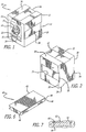
Figure 1 is a front perspective view of a watchwinder embodying the novel features of the present invention. -
FIG. 2 is a rear perspective view of the watchwinder shown inFIG. 1 . -
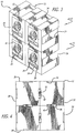
FIG. 3 is a front perspective view of an integrated array of interconnected watchwinders of the type shown inFIG. 1 . -
FIG. 4 is a rear elevational view of the watchwinder array shown inFIG. 3 . -
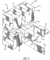
FIG. 5 is an exploded rear perspective view of the watchwinder array shown inFIGS. 3 and 4 . -
FIG. 6 is an enlarged perspective view of one of the interlocking bars shown inFIGS. 4 and5 . -
FIG. 7 is an enlarged, fragmentary, sectional view showing the interlocking bar inFIG 6 in place for holding adjacent watchwinders together. - As shown in the drawings, which are provided for purposes of exemplary illustration, the invention is embodied in a new and improved
watchwinder 10, which is capable of being used individually or as part of a customizable and re-configurable grouping of interlocked watchwinders. - Preferably, as illustrated in
Fig. 1 thewatchwinder 10 includes ahousing 12 of approximately cubic in form, although other shapes or forms of housing also are contemplated by the present invention. Thefront surface 14 of thehousing 12 has an opening therein for receiving a watchwinder mechanism of conventional design. While one or more watchwinder mechanisms could be mounted in a single housing, one mechanism per housing is preferred for the present invention. - The watchwinder mechanism includes a circular,
hollow drum 16, adapted to rotate on its axis, mounted within thehousing 12, preferably on an upright generally vertical surface, although it is also contemplated that the front face may slope at an angle less than perpendicular to the base. Acuff 18 removably inserted within thedrum 16 is adapted to hold a self-windingwristwatch 20 on the drum so that the face of the watch is visible from the front of thewatchwinder 10. When thedrum 16 rotates with thewatch 20 andcuff 18 in place, the watch rotates within the plane of the watch face, thereby winding the self-winding mechanism of the watch. - In a preferred embodiment, each
watchwinder 10 is powered by a small electric motor and associated electronic control circuit (not shown) located within thehousing 12. The electronic circuit may be adapted to wind the watch in a first direction, to pause, and then wind the watch in a second direction with each rotation being performed for a pre-determined number of cycles. Various modes of rotation, controlled by the circuit, also may be selected by settingcontrol buttons 22 on thefront face 14 of thewatchwinder 10. In a preferred embodiment, four settings are provided, namely off, clockwise rotation, anti-clockwise rotation, and reversing rotation - that is, clockwise followed by anti-clockwise rotation and so on repeating. Preferably, eachwatchwinder 10 will be separately powered by its own battery power supply placed in a removable drawer (not shown) in the rear of thehousing 12. Atypical watchwinder 10 is illustrated and described in my co-pendingUS Application, Serial No. 10/845,463, filed May 12, 2004 2005/0254352 . - It is preferred that at least the top 26, bottom 28, and side surfaces 30 of the
housing 12 are formed as a one-piece molded plastic part. - Preferably, the
front 14 of thewatchwinder 10 is left open to allow the user direct access to thedrum 16 andcontrol buttons 22. However, a hinged protective glass cover or glass-front door (not shown) may be provided, if desired. - In accordance with the present invention, a
connector 32 is provided on at least one surface of thehousing 12, and preferably on thesides 30, top 26 and bottom 28 surfaces of thehousing 12, to permit adjacent watchwinders of like construction to be securely and detachably interlocked with each other in a side-by-side and/or vertical relationship. - Preferably, each of the
connectors 32 is a female type connector affixed to thewatchwinder 10, which provides the advantage that it does not protrude outwardly beyond the perimeter of thehousing 12. - In a further preferred embodiment, each of the
connectors 32 is an outwardly opening horizontal groove orchannel 34 formed on an outer portion of each wall surface. Eachchannel 34 starts on therear edge 36 of the wall surface and extends substantially continuously across the entire horizontal dimension of the wall surface to a point short of thefront 14 of thehousing 12 By stopping short of thefront 14 of thehousing 12, thechannel 34 is not visible from a front view of thewatchwinder 10 and does not unduly weaken the watchwinder structure. - Each horizontal groove or
channel 34 is preferably undercut so as to have an inside cross-section which widens toward the interior of thewatchwinder 10, thereby producing a groove of dovetail cross-sectional shape. A horizontal groove of dovetail shape is especially advantageous because it resists the separation ofinterconnected watchwinders 10 in a transverse direction, while permitting the watchwinders to be easily assembled and disassembled by horizontal forward and rearward sliding, in a manner to be described. - The
horizontal channels 34 are preferably of equal size and shape and spaced equidistantly apart around thesides 30, top 26 and bottom 28 surfaces of thewatchwinder housing 12, providing a universal watchwinder construction which may be interlocked with likewatchwinders 10 arranged in a vertical or side-by-side relationship. - Preferably, each of the
channels 34 is centered on the wall of thehousing 12 and is made relatively wide and shallow as compared to the surface dimensions of thehousing 12, Awide groove 34 helps to distribute the connecting load across a broader area which increases the tortional rigidity of a grouping ofinterconnected watchwinders 10 while allowingadjacent watchwinders 10 to be joined with a single interlocking bar 40 (to be described) thereby simplifying assembly for the end user A shallow groove helps to maintain the structural integrity and sleek visual appearance of thewatchwinder housing 12. - Preferably, the width of the
groove 34 is approximately half or more of the width of the surface on which the groove is located. For example, in atypical watchwinder 10 withhousing 12 dimensions of 12 cm W x 15 cm H x 10 cm D, the groove orchannel 34 on the top, bottom and side surfaces would preferably be about 7 cm in width at the opening and about 8 cm in width at the deepest part. The groove depth would preferably be about 5 mm. -
Adjacent watchwinders 10 of the type described above may be connected together in a secure manner with a removable interlocking bar orrail 40 of the type shown inFig. 6 . Preferably, each of the interlocking bars 40 is adapted for longitudinal sliding engagement with thechannels 34 onadjacent watchwinders 10 to form a dovetailed joint that resists being pulled apart laterally. - In a preferred form, each of the interlocking bars or rails 40 is an
elongate member 42 with back-to-back oppositely disposedmale attachment structures middle section 48 and adapted to slide snugly into thechannels 34 of corresponding dovetail shape, Theelongate member 42 preferably has a length equal to the length of the grooves or channels on thewatchwinder housing 12. - As shown in detail in
Fig. 7 , theside walls 50 of themale members male members side walls 50 of themale members side walls 54 of thechannels 34, when joined together, thus dovetail with one another to lock thewatchwinders 10 together and resist movement in a plane normal to the plane of the wall of the watchwinder, while permitting relative movement in at least one direction in the plane of the watchwinder wall. -
Figs. 3-5 illustrate how an interlockingarray 60 ofwatchwinders 10 may be built up using a collection ofwatchwinders 10 of the type shown inFigs 1-2 . - As shown in
Figs 3-5 , thearray 60 is assembled by stacking thewatchwinders 10 vertically and/or by placing them side-by-side and aligning thechannels 34 on adjacent watchwinders. The like,adjacent watchwinders 10 are then interlocked to one another to form an integrated unit by inserting the interlocking bars 40 of the type shown inFig. 6 , so that eachmale mating half bar 40 snuggly slides into theadjacent channel 34 until the bar abuts theforward end 62 of thechannel 34 the rearward end of thebar 40 is flush with the rear surface of thehousing 12, The dovetail shape of themale mating members horizontal channels 34 ensuring that thewatchwinders 10 when so mated are securely locked to one another laterally and held firmly in place. - As indicated, the interlocking
bars 40 can be inserted after thewatchwinders 10 are aligned or, alternatively, eachbar 40 first can be inserted fully into one of a pair of adjacent watchwinders, then while the interlockingbar 40 is held stationary by hand or other means, the second adjacent watchwinder is brought into engaging alignment with the first watchwinder by sliding it horizontally rearwardly over the exposed male mating half of the interlockingbar 40 until the bar abuts theforward end 62 of thechannel 34 on the second watchwinder housing. - The interlocking bars 40 could be considered as adapters in the sense that they convert the
female connectors 32 on eachwatchwinder housing 12 into a male connector for mating with thefemale connectors 32 onadjacent watchwinders 10. - Either way, the entire array is given rigidity by the interlocking nature of the interlocking bars 40 in the
horizontal channels 34. The integrated visual appearance of a conventional multi-rotator watchwinder is maintained since thebars 40 andchannels 34 are not visible from the front of thearray 60. - When assembled in this manner, the
array 60 offers many of the same advantages as a conventional multi-rotator watchwinder, most notably, the ability to conveniently store and independently rotate a plurality of watches in a single integrated unit. - However, the
array 60 has the additional advantage that it can be disassembled for travel, storage or other purposes by sliding each watchwinder 10 in thearray 60 forwardly relative to the remainder of the array until the watchwinder is disengaged from the array The exposed interlockingbars 40 can then be removed from thearray 60 by sliding them rearwardly in a longitudinal direction. - It will be appreciated that the interlocking bars 40 can be glued or otherwise fastened in place to form a permanent assembly, if desired. However, the preferred approach is to join the
bars 40 with thechannels 34 without any additional fasteners or glue so as to provide a knockdown or re-configurable assembly. - While
Figs. 3-5 show fourwatchwinders 10 arranged in a rectangular grid pattern, it will be understood that the array can be built up to any desired size or shape and with any number of watchwinders. The size of the array or number of watchwinders within the array is virtually unlimited. The height of the array is only limited by the structural strength and weight of thewatchwinders 10 themselves. - Even after initial assembly, the size or shape of an
array 60, or number ofwatchwinders 10 in thearray 60, can be altered by selectively adding or removingwatchwinders 10 from thearray 60, either vertically or horizontally in any chosen pattern. - Any interlocked
watchwinder 10 can be removed from anywhere within thearray 60 without disturbing the remainder of the array by translating the watchwinder in a forward horizontal direction with respect to thearray 60, even if thewatchwinder 10 is located in a central portion of thearray 60 and is mated with and bridges across two or more adjacent watchwinders. - A comparison of
Figs. 1-2 withFigs, 3-5 illustrates that the present invention allows the user to choose between a single rotator watchwinder configuration or a multi-rotator watchwinder configuration, as needed, with a minimum variety of basic components, ease of assembly and disassembly, and maximum flexibility, and with the added benefit that the multi-rotator assembly (1) is re-configurable and customizable to adapt to varying needs, (2) permits individual watchwinders to be selectively removed from anywhere within the array for any reason without disrupting the rest of the array, and (3) securely joins adjacent watchwinders to each other so that the array cannot be accidentally disturbed or disrupted and can be moved as an integral unit for storage and the like.
Claims (16)
- A watchwinder (10) apparatus, comprising:a housing (12) having an outer surface (26, 28, 30);a watch rotating structure (16, 18) mounted within the housing (12) configured to hold and rotate a self-winding watch (20);a motor disposed within the housing (12) and operatively connected to the watch rotating structure (16, 18);characterized in that the watchwinder (10) further comprises:at least one connector (32) comprising an outwardly opening horizontal channel (34) formed on an outer surface (26, 28, 30) of the housing (12) for selectively and detachably connecting adjacent watchwinders (10) to one another; andan interlocking member (40) for detachably engaging said at least one connector (32) to selectively and detachably interconnect said adjacent watchwinders (10) to one another; andwherein said interlocking member (40) is a removable interlocking bar or rail (40) adapted for longitudinal sliding engagement with said horizontal channels (34) on adjacent watchwinders (10).
- Apparatus as set forth in claim 1, wherein said housing (12) has top (26), bottom (28) and side (30) surfaces, and each of said top (26), bottom (28) and side (30) surfaces has at least one connector (32) formed thereon.
- Apparatus as set forth in claim 2, wherein said connectors (32) are substantially identical to each other and spaced equidistantly apart around the sides (30), top (26) and bottom (28) surfaces of said housing (12).
- Apparatus as set forth in claim 2, wherein each of said connectors comprises an outwardly opening horizontal channel (34) of dovetail cross-sectional shape.
- Apparatus as set forth in claim 4, wherein said channel (34) has a width of about one-half or more of the width of the surface (26, 28, 30) on which said channel (34) is disposed.
- Apparatus as set forth in claim 4, wherein said interlocking member has oppositely disposed male portions of dovetail cross-sectional shape corresponding to the cross-sectional shape of said channels for slidably engaging said channels in a longitudinal sliding manner to securely connect said adjacent watchwinders to one another.
- Apparatus as set forth in claim 1, wherein said housing (12) is formed as a one-piece molded plastic part.
- Apparatus as set forth in claim 2, wherein an array of said interconnected watchwinders (10) can be formed, in which connectors (32) on adjacent watchwinder (10) housings (12) are vertically aligned when said watchwinders (10) are stacked on top of one another and laterally aligned when said watchwinders (10) are placed beside each other.
- Apparatus as set forth in claim 8, wherein said bar or rail (40) is selectively and detachably interconnecting an adjacent pair of said watchwinders (10) when said watchwinders (10) are in a side-by-side relation and an adjacent pair of said watchwinders (10) when said watchwinders (10) are in a vertical columnar relation.
- Apparatus as set forth in claim 8, wherein said channel (34) extends continuously from a rear portion (36) of said housing (12) to a point short of the front (14) of said housing (12).
- Apparatus as set forth in claim 8, wherein one or more of said watchwinders (10) may be selectively removed from anywhere within said array by translating said watchwinder (10) horizontally with respect to the remainder of the array.
- Apparatus as set forth in claim 10, wherein said channel (34) has a width of about one-half or more of the width of the surface (26, 28, 30) on which said channel (34) is disposed.
- Apparatus as set forth in claim 8, wherein a single connector (32) is disposed on each of said top (26), bottom (28) and side (30) surfaces.
- Apparatus as set forth in claim 2, wherein said channels (34) are of equal size and shape.
- Apparatus as set forth in claim 14, wherein said channels (34) are spaced equidistantly apart around the sides (30), top (26) and bottom (28) of said housing (12).
- Apparatus as set forth in claim 1, wherein the watch rotating structure is mounted within the housing (12) on a generally upright surface thereof.
Applications Claiming Priority (1)
| Application Number | Priority Date | Filing Date | Title |
|---|---|---|---|
| US11/385,080 US7410289B2 (en) | 2006-03-21 | 2006-03-21 | Interlockable watchwinder |
Publications (3)
| Publication Number | Publication Date |
|---|---|
| EP1847890A2 EP1847890A2 (en) | 2007-10-24 |
| EP1847890A3 EP1847890A3 (en) | 2011-05-11 |
| EP1847890B1 true EP1847890B1 (en) | 2018-01-10 |
Family
ID=38472142
Family Applications (1)
| Application Number | Title | Priority Date | Filing Date |
|---|---|---|---|
| EP07104532.2A Active EP1847890B1 (en) | 2006-03-21 | 2007-03-20 | Interlockable watchwinder |
Country Status (2)
| Country | Link |
|---|---|
| US (1) | US7410289B2 (en) |
| EP (1) | EP1847890B1 (en) |
Families Citing this family (31)
| Publication number | Priority date | Publication date | Assignee | Title |
|---|---|---|---|---|
| US20070228252A1 (en) * | 2006-04-04 | 2007-10-04 | Inventec Corporation | Fixing device |
| KR20080073184A (en) * | 2007-02-21 | 2008-08-08 | 박진호 | Prefabricated furniture using storage module and storage module |
| US20090225632A1 (en) * | 2008-03-07 | 2009-09-10 | Charles Agnoff | Combination watch winder and display |
| US7927009B2 (en) * | 2008-12-27 | 2011-04-19 | Abest Products Resourcing Inc. | Watch winder |
| DE102009034109B3 (en) * | 2009-07-21 | 2010-11-25 | Andreas Fuld | Uhrenbewegersystem |
| EP2689293A1 (en) * | 2011-03-23 | 2014-01-29 | I.m.h. Innovations Manfactures Horlogères SA | Multifunctional case |
| US20130106268A1 (en) * | 2011-10-26 | 2013-05-02 | Ming-Hwa Hsu | Structure of knockdown cabinet |
| US10219400B2 (en) * | 2016-06-14 | 2019-02-26 | Ovh | Transportable and stackable server racks |
| CH713822A2 (en) * | 2017-05-29 | 2018-11-30 | Swatch Group Res & Dev Ltd | Apparatus and method for gait adjustment and state correction of a watch |
| RU2761261C2 (en) | 2017-05-29 | 2021-12-06 | Те Свотч Груп Рисерч Энд Дивелопмент Лтд | Device and method for regulating stroke and adjusting clock readings |
| USD905144S1 (en) * | 2018-05-23 | 2020-12-15 | Jiamei Holdings Limited | Single watch winder |
| USD905773S1 (en) * | 2018-05-23 | 2020-12-22 | Jiamei Holdings Limited | Double watch winder |
| DE102018120136A1 (en) * | 2018-08-17 | 2020-02-20 | Rickard Nilsson | Pushing device for exerting a compressive force against goods of a goods presentation device, shelf unit and goods presentation device |
| US10642224B1 (en) * | 2019-07-02 | 2020-05-05 | Fernando Macias Garza | Watch winding apparatus for winding a wrist watch and method thereof |
| KR102243046B1 (en) * | 2019-08-08 | 2021-04-21 | (주)엠블럭 | Module type asembly display case |
| USD930059S1 (en) * | 2020-01-04 | 2021-09-07 | Yuemi Huang | Watch winder |
| USD931923S1 (en) * | 2020-01-13 | 2021-09-28 | Yuemi Huang | Watch winder |
| USD937921S1 (en) * | 2020-08-26 | 2021-12-07 | Yuemi Huang | Watch winder |
| US12019400B2 (en) * | 2020-11-02 | 2024-06-25 | Wolf 1834 | Extendable cuff for watch winders |
| USD952721S1 (en) * | 2020-12-14 | 2022-05-24 | Kehuangda (Guangzhou) Trading Co., Ltd. | Winder for watch |
| USD950617S1 (en) * | 2020-12-14 | 2022-05-03 | Kehuangda (Guangzhou) Trading Co., Ltd. | Winder for watch |
| USD1028046S1 (en) * | 2021-05-24 | 2024-05-21 | Wolf 1834 | Watch winder turntable flange |
| USD1025159S1 (en) * | 2021-05-24 | 2024-04-30 | Wolf 1834 | Watch winder |
| USD968493S1 (en) * | 2021-06-04 | 2022-11-01 | Kehuangda (Guangzhou) Trading Co., Ltd. | Watch winder |
| USD988384S1 (en) * | 2021-06-07 | 2023-06-06 | Beri{hacek over (s)}aj, napredne informacijske re{hacek over (s)}itve, d.o.o. | Watch winder |
| USD982637S1 (en) * | 2021-06-07 | 2023-04-04 | Beri{hacek over (s)}aj, napredne informacijske re{hacek over (s)}itve, d.o.o. | Stand for a single watch winder |
| USD970574S1 (en) * | 2021-07-05 | 2022-11-22 | Qiaohong Chen | Watch box |
| USD1026987S1 (en) * | 2022-05-11 | 2024-05-14 | Shijiazhuang Yingzhan Trading Co., Ltd. | Winder for watch |
| USD967222S1 (en) * | 2022-06-29 | 2022-10-18 | Turning P Trading Co., Ltd. | Watch winder |
| USD1041526S1 (en) * | 2024-06-17 | 2024-09-10 | Guangzhou Aojun International Trading Co., Ltd. | Watch winder |
| US12569079B2 (en) * | 2024-07-03 | 2026-03-10 | Fraction Watch Box, Llc | Suspended watch holder display container |
Family Cites Families (43)
| Publication number | Priority date | Publication date | Assignee | Title |
|---|---|---|---|---|
| US1076116A (en) | 1911-06-26 | 1913-10-21 | John Hatfield | Unit filing-cabinet. |
| US1736651A (en) | 1927-07-21 | 1929-11-19 | Glaenzer Jules | Cigarette box |
| US1983307A (en) | 1933-10-11 | 1934-12-04 | Walter F Regenhardt | Sectional filing cabinet |
| US2917955A (en) * | 1956-11-19 | 1959-12-22 | Sterling Multi Products Inc | Testing device for self-winding mechanisms |
| US3107131A (en) | 1961-07-11 | 1963-10-15 | Robert A Lightburn | Sectional drawer cabinet |
| US3374917A (en) | 1964-01-09 | 1968-03-26 | Constantine T. Troy | Interlocking structural elements |
| DE1453822C3 (en) | 1965-03-24 | 1975-11-13 | Dynamit Nobel Ag, 5210 Troisdorf | Packaging containers, in particular for rockets or rocket-like projectiles |
| US3552817A (en) | 1967-08-31 | 1971-01-05 | Terry Plastic Di Guizzardi Cla | Compartmented storage cabinet |
| US3514170A (en) * | 1968-01-10 | 1970-05-26 | Donald Shewchuk | Stackable and interlocking containers |
| US3778870A (en) | 1971-12-29 | 1973-12-18 | Mattern Ware And Dairs | Statistical hook and loop area fasteners |
| US3836218A (en) | 1972-11-24 | 1974-09-17 | A Hallal | Connecting device for modular constructions |
| US3851936A (en) | 1973-08-16 | 1974-12-03 | Donat Talbot Archambult | Attachment device for modular units |
| US3999818A (en) | 1975-06-20 | 1976-12-28 | Microfilm Enterprises Corporation | Modular storage system |
| US4003172A (en) | 1975-09-30 | 1977-01-18 | Pawl Walter S | Peripherally grooved building blocks in a wall construction |
| US4056295A (en) | 1976-03-01 | 1977-11-01 | Caterpillar Tractor Co. | Multiple container and rack system |
| DE2802460A1 (en) | 1978-01-20 | 1979-07-26 | Idn Invention Dev Novelties | STACKING DEVICE |
| US4227758A (en) | 1978-04-20 | 1980-10-14 | Clare George M | Connectors for holding together modular articles |
| US4182244A (en) | 1978-11-02 | 1980-01-08 | The Mead Corporation | Modular display device |
| CA1092062A (en) | 1979-04-20 | 1980-12-23 | Paul L. Leblanc | Storage and display assembly |
| US4372445A (en) | 1981-02-19 | 1983-02-08 | Keffeler Paul J | Medication dispenser |
| US4423913A (en) | 1981-11-03 | 1984-01-03 | Lee William J | Display and storage assembly utilizing a plurality of interchangeable stackable bins |
| US4470647A (en) | 1982-06-01 | 1984-09-11 | Mark L. Bishoff | Interfitting and removable modular storage units including connectors forming part of a unit as well as sliding support for adjacent units |
| US4577914A (en) | 1984-05-16 | 1986-03-25 | Stravitz David M | Assembly of slidably interfitting storage units |
| US4737039A (en) | 1986-12-08 | 1988-04-12 | Knape & Vogt Manufacturing Company | Drawer rail carrier roller mount |
| US4903451A (en) | 1988-10-14 | 1990-02-27 | Gressco, Ltd. | Modular system and fastening devices therefor |
| US5046789A (en) | 1990-04-05 | 1991-09-10 | Alvin Lee Jewelry, Inc. | Modular panel assembly |
| US5267863A (en) | 1992-10-02 | 1993-12-07 | Simmons Jr Felix J | Interlocking pixel blocks and beams |
| CA2101139A1 (en) | 1993-07-22 | 1995-01-23 | Richard Alpen | Interlocking front-load bulk storage containers |
| US5775046A (en) | 1996-05-10 | 1998-07-07 | Massachusetts Institute Of Technology | Modular construction member |
| US5924778A (en) | 1997-07-14 | 1999-07-20 | Tenbrink; Carl Evan | Modular display case |
| FR2784721A1 (en) * | 1998-10-14 | 2000-04-21 | Gerard Racine | Vee shaped structure and its fabrication for use in assembly of furniture in kit form |
| US6050657A (en) | 1999-02-08 | 2000-04-18 | Hiltzman; Jerry R. | Shelf organizer system |
| EP1136893A1 (en) * | 2000-03-20 | 2001-09-26 | Underwood (London) Limited | Watch winding apparatus |
| US20020070641A1 (en) | 2000-12-08 | 2002-06-13 | Ragan Sean Michael | Two-way stacking and nesting book boxes with interposing slat construction |
| USD452256S1 (en) | 2001-03-15 | 2001-12-18 | Wolf Designs, Inc. | Automatic watch rotator box |
| US6532878B2 (en) | 2001-05-29 | 2003-03-18 | W. Scott Tidemann | Slot-to-slot interlocking shelving |
| US7100999B2 (en) * | 2002-05-30 | 2006-09-05 | Stravitz David M | System of interlocking storage and display modules connectable in a plurality of different configurations |
| DE20209739U1 (en) * | 2002-06-24 | 2002-12-19 | Tischlerei T 2 Möbel GmbH, 55278 Hahnheim | Connection element for box-shaped furniture elements |
| ITMI20030270U1 (en) * | 2003-06-09 | 2004-12-10 | S C S & Co S R L | SUPPORT STRUCTURE AND FOR RECHARGING PARTICULARLY FOR AUTOMATIC WRISTWATCHES |
| US7575367B2 (en) | 2004-05-12 | 2009-08-18 | Wolf Designs, Inc. | Controllable watch winder for self-winding watches |
| US20050265129A1 (en) * | 2004-05-28 | 2005-12-01 | Charles Agnoff | Watch winder cabinet and watch winder apparatus |
| US20060028922A1 (en) | 2004-08-06 | 2006-02-09 | Wolf Simon P V | System and method for displaying self-winding watches |
| US6964513B1 (en) * | 2004-12-09 | 2005-11-15 | Charles Agnoff | Cylinder watch winder |
-
2006
- 2006-03-21 US US11/385,080 patent/US7410289B2/en not_active Expired - Lifetime
-
2007
- 2007-03-20 EP EP07104532.2A patent/EP1847890B1/en active Active
Non-Patent Citations (1)
| Title |
|---|
| None * |
Also Published As
| Publication number | Publication date |
|---|---|
| US7410289B2 (en) | 2008-08-12 |
| US20070223319A1 (en) | 2007-09-27 |
| EP1847890A2 (en) | 2007-10-24 |
| EP1847890A3 (en) | 2011-05-11 |
Similar Documents
| Publication | Publication Date | Title |
|---|---|---|
| US7410289B2 (en) | Interlockable watchwinder | |
| EP1358410B1 (en) | Assemble-in-place modular storage | |
| AU2024203352B2 (en) | Swing apparatus with magnetic drive and control | |
| US6206493B1 (en) | Display structure for collectibles | |
| EP0784556B1 (en) | Trolley handle unit | |
| US6417645B1 (en) | Combination holder and battery charger | |
| US20070159929A1 (en) | Watch-winding apparatus | |
| KR19990072995A (en) | Cabinet having a tambour door and an attatchment mechanism | |
| USD460129S1 (en) | Interconnectable play cube | |
| US20140235133A1 (en) | Structure building toy | |
| HK1109937B (en) | Interlockable watchwinder | |
| US20070207862A1 (en) | Video game console pedestal and multi-media hub | |
| HK1109937A (en) | Interlockable watchwinder | |
| AU5146699A (en) | A laser with the resonance cavity including a circular cone prism being top in shape | |
| USD488435S1 (en) | Rechargeable battery for optical disc player | |
| US20060028922A1 (en) | System and method for displaying self-winding watches | |
| KR20110001745U (en) | Storage shelf capable of mounting door at fastening member | |
| WO2018157223A1 (en) | Magnetic toy building block | |
| CN2170688Y (en) | Glasses display stand that can be easily moved | |
| US6543627B1 (en) | Shelf construction | |
| KR102338617B1 (en) | A rotating table | |
| CN203016419U (en) | Roller slide display shelving structure | |
| USD455183S1 (en) | Interconnectable play cube | |
| CN108851824A (en) | A kind of jewelry exhibition cabinet that safety coefficient is high | |
| CN217408350U (en) | Exhibition cabinet |
Legal Events
| Date | Code | Title | Description |
|---|---|---|---|
| PUAI | Public reference made under article 153(3) epc to a published international application that has entered the european phase |
Free format text: ORIGINAL CODE: 0009012 |
|
| AK | Designated contracting states |
Kind code of ref document: A2 Designated state(s): AT BE BG CH CY CZ DE DK EE ES FI FR GB GR HU IE IS IT LI LT LU LV MC MT NL PL PT RO SE SI SK TR |
|
| AX | Request for extension of the european patent |
Extension state: AL BA HR MK YU |
|
| REG | Reference to a national code |
Ref country code: HK Ref legal event code: DE Ref document number: 1109937 Country of ref document: HK |
|
| PUAL | Search report despatched |
Free format text: ORIGINAL CODE: 0009013 |
|
| AK | Designated contracting states |
Kind code of ref document: A3 Designated state(s): AT BE BG CH CY CZ DE DK EE ES FI FR GB GR HU IE IS IT LI LT LU LV MC MT NL PL PT RO SE SI SK TR |
|
| AX | Request for extension of the european patent |
Extension state: AL BA HR MK RS |
|
| 17P | Request for examination filed |
Effective date: 20111111 |
|
| AKX | Designation fees paid |
Designated state(s): CH DE GB LI |
|
| 17Q | First examination report despatched |
Effective date: 20130508 |
|
| GRAP | Despatch of communication of intention to grant a patent |
Free format text: ORIGINAL CODE: EPIDOSNIGR1 |
|
| STAA | Information on the status of an ep patent application or granted ep patent |
Free format text: STATUS: GRANT OF PATENT IS INTENDED |
|
| INTG | Intention to grant announced |
Effective date: 20170706 |
|
| RAP1 | Party data changed (applicant data changed or rights of an application transferred) |
Owner name: WOLF DESIGNS, INC. |
|
| GRAS | Grant fee paid |
Free format text: ORIGINAL CODE: EPIDOSNIGR3 |
|
| GRAA | (expected) grant |
Free format text: ORIGINAL CODE: 0009210 |
|
| STAA | Information on the status of an ep patent application or granted ep patent |
Free format text: STATUS: THE PATENT HAS BEEN GRANTED |
|
| AK | Designated contracting states |
Kind code of ref document: B1 Designated state(s): CH DE GB LI |
|
| REG | Reference to a national code |
Ref country code: GB Ref legal event code: FG4D |
|
| REG | Reference to a national code |
Ref country code: CH Ref legal event code: EP Ref country code: CH Ref legal event code: NV Representative=s name: E. BLUM AND CO. AG PATENT- UND MARKENANWAELTE , CH |
|
| REG | Reference to a national code |
Ref country code: DE Ref legal event code: R096 Ref document number: 602007053705 Country of ref document: DE |
|
| REG | Reference to a national code |
Ref country code: CH Ref legal event code: NV Representative=s name: ISLER AND PEDRAZZINI AG, CH |
|
| REG | Reference to a national code |
Ref country code: HK Ref legal event code: GR Ref document number: 1109937 Country of ref document: HK |
|
| REG | Reference to a national code |
Ref country code: DE Ref legal event code: R097 Ref document number: 602007053705 Country of ref document: DE |
|
| PLBE | No opposition filed within time limit |
Free format text: ORIGINAL CODE: 0009261 |
|
| STAA | Information on the status of an ep patent application or granted ep patent |
Free format text: STATUS: NO OPPOSITION FILED WITHIN TIME LIMIT |
|
| 26N | No opposition filed |
Effective date: 20181011 |
|
| P01 | Opt-out of the competence of the unified patent court (upc) registered |
Effective date: 20230329 |
|
| REG | Reference to a national code |
Ref country code: DE Ref legal event code: R082 Ref document number: 602007053705 Country of ref document: DE Representative=s name: GRUENECKER PATENT- UND RECHTSANWAELTE PARTG MB, DE Ref country code: DE Ref legal event code: R081 Ref document number: 602007053705 Country of ref document: DE Owner name: WOLF 1834, EL SEGUNDO, US Free format text: FORMER OWNER: WOLF DESIGNS, INC., INGELWOOD, CALIF., US |
|
| REG | Reference to a national code |
Ref country code: CH Ref legal event code: PK Free format text: BERICHTIGUNGEN |
|
| PGFP | Annual fee paid to national office [announced via postgrant information from national office to epo] |
Ref country code: CH Payment date: 20250401 Year of fee payment: 19 |
|
| REG | Reference to a national code |
Ref country code: CH Ref legal event code: U11 Free format text: ST27 STATUS EVENT CODE: U-0-0-U10-U11 (AS PROVIDED BY THE NATIONAL OFFICE) Effective date: 20260401 |
|
| PGFP | Annual fee paid to national office [announced via postgrant information from national office to epo] |
Ref country code: GB Payment date: 20260327 Year of fee payment: 20 |
|
| PGFP | Annual fee paid to national office [announced via postgrant information from national office to epo] |
Ref country code: DE Payment date: 20260327 Year of fee payment: 20 |