EP1847850A2 - Hydrophone assembly - Google Patents
Hydrophone assembly Download PDFInfo
- Publication number
- EP1847850A2 EP1847850A2 EP20070012105 EP07012105A EP1847850A2 EP 1847850 A2 EP1847850 A2 EP 1847850A2 EP 20070012105 EP20070012105 EP 20070012105 EP 07012105 A EP07012105 A EP 07012105A EP 1847850 A2 EP1847850 A2 EP 1847850A2
- Authority
- EP
- European Patent Office
- Prior art keywords
- hydrophone
- accelerometer
- output
- frequency
- frequency response
- Prior art date
- Legal status (The legal status is an assumption and is not a legal conclusion. Google has not performed a legal analysis and makes no representation as to the accuracy of the status listed.)
- Granted
Links
Images


Classifications
-
- G—PHYSICS
- G01—MEASURING; TESTING
- G01P—MEASURING LINEAR OR ANGULAR SPEED, ACCELERATION, DECELERATION, OR SHOCK; INDICATING PRESENCE, ABSENCE, OR DIRECTION, OF MOVEMENT
- G01P1/00—Details of instruments
- G01P1/02—Housings
- G01P1/023—Housings for acceleration measuring devices
-
- B—PERFORMING OPERATIONS; TRANSPORTING
- B81—MICROSTRUCTURAL TECHNOLOGY
- B81B—MICROSTRUCTURAL DEVICES OR SYSTEMS, e.g. MICROMECHANICAL DEVICES
- B81B3/00—Devices comprising flexible or deformable elements, e.g. comprising elastic tongues or membranes
- B81B3/0002—Arrangements for avoiding sticking of the flexible or moving parts
- B81B3/001—Structures having a reduced contact area, e.g. with bumps or with a textured surface
-
- B—PERFORMING OPERATIONS; TRANSPORTING
- B81—MICROSTRUCTURAL TECHNOLOGY
- B81B—MICROSTRUCTURAL DEVICES OR SYSTEMS, e.g. MICROMECHANICAL DEVICES
- B81B3/00—Devices comprising flexible or deformable elements, e.g. comprising elastic tongues or membranes
- B81B3/0064—Constitution or structural means for improving or controlling the physical properties of a device
- B81B3/0067—Mechanical properties
- B81B3/0072—For controlling internal stress or strain in moving or flexible elements, e.g. stress compensating layers
-
- B—PERFORMING OPERATIONS; TRANSPORTING
- B81—MICROSTRUCTURAL TECHNOLOGY
- B81B—MICROSTRUCTURAL DEVICES OR SYSTEMS, e.g. MICROMECHANICAL DEVICES
- B81B7/00—Microstructural systems; Auxiliary parts of microstructural devices or systems
- B81B7/0009—Structural features, others than packages, for protecting a device against environmental influences
- B81B7/0016—Protection against shocks or vibrations, e.g. vibration damping
-
- G—PHYSICS
- G01—MEASURING; TESTING
- G01D—MEASURING NOT SPECIALLY ADAPTED FOR A SPECIFIC VARIABLE; ARRANGEMENTS FOR MEASURING TWO OR MORE VARIABLES NOT COVERED IN A SINGLE OTHER SUBCLASS; TARIFF METERING APPARATUS; MEASURING OR TESTING NOT OTHERWISE PROVIDED FOR
- G01D11/00—Component parts of measuring arrangements not specially adapted for a specific variable
- G01D11/24—Housings ; Casings for instruments
- G01D11/245—Housings for sensors
-
- G—PHYSICS
- G01—MEASURING; TESTING
- G01D—MEASURING NOT SPECIALLY ADAPTED FOR A SPECIFIC VARIABLE; ARRANGEMENTS FOR MEASURING TWO OR MORE VARIABLES NOT COVERED IN A SINGLE OTHER SUBCLASS; TARIFF METERING APPARATUS; MEASURING OR TESTING NOT OTHERWISE PROVIDED FOR
- G01D18/00—Testing or calibrating apparatus or arrangements provided for in groups G01D1/00 - G01D15/00
- G01D18/008—Testing or calibrating apparatus or arrangements provided for in groups G01D1/00 - G01D15/00 with calibration coefficients stored in memory
-
- G—PHYSICS
- G01—MEASURING; TESTING
- G01P—MEASURING LINEAR OR ANGULAR SPEED, ACCELERATION, DECELERATION, OR SHOCK; INDICATING PRESENCE, ABSENCE, OR DIRECTION, OF MOVEMENT
- G01P15/00—Measuring acceleration; Measuring deceleration; Measuring shock, i.e. sudden change of acceleration
- G01P15/02—Measuring acceleration; Measuring deceleration; Measuring shock, i.e. sudden change of acceleration by making use of inertia forces using solid seismic masses
- G01P15/08—Measuring acceleration; Measuring deceleration; Measuring shock, i.e. sudden change of acceleration by making use of inertia forces using solid seismic masses with conversion into electric or magnetic values
- G01P15/0802—Details
-
- G—PHYSICS
- G01—MEASURING; TESTING
- G01P—MEASURING LINEAR OR ANGULAR SPEED, ACCELERATION, DECELERATION, OR SHOCK; INDICATING PRESENCE, ABSENCE, OR DIRECTION, OF MOVEMENT
- G01P15/00—Measuring acceleration; Measuring deceleration; Measuring shock, i.e. sudden change of acceleration
- G01P15/02—Measuring acceleration; Measuring deceleration; Measuring shock, i.e. sudden change of acceleration by making use of inertia forces using solid seismic masses
- G01P15/08—Measuring acceleration; Measuring deceleration; Measuring shock, i.e. sudden change of acceleration by making use of inertia forces using solid seismic masses with conversion into electric or magnetic values
- G01P15/13—Measuring acceleration; Measuring deceleration; Measuring shock, i.e. sudden change of acceleration by making use of inertia forces using solid seismic masses with conversion into electric or magnetic values by measuring the force required to restore a proofmass subjected to inertial forces to a null position
-
- G—PHYSICS
- G01—MEASURING; TESTING
- G01P—MEASURING LINEAR OR ANGULAR SPEED, ACCELERATION, DECELERATION, OR SHOCK; INDICATING PRESENCE, ABSENCE, OR DIRECTION, OF MOVEMENT
- G01P21/00—Testing or calibrating of apparatus or devices covered by the preceding groups
-
- G—PHYSICS
- G01—MEASURING; TESTING
- G01V—GEOPHYSICS; GRAVITATIONAL MEASUREMENTS; DETECTING MASSES OR OBJECTS; TAGS
- G01V1/00—Seismology; Seismic or acoustic prospecting or detecting
- G01V1/02—Generating seismic energy
- G01V1/04—Details
- G01V1/047—Arrangements for coupling the generator to the ground
- G01V1/053—Arrangements for coupling the generator to the ground for generating transverse waves
-
- G—PHYSICS
- G01—MEASURING; TESTING
- G01V—GEOPHYSICS; GRAVITATIONAL MEASUREMENTS; DETECTING MASSES OR OBJECTS; TAGS
- G01V1/00—Seismology; Seismic or acoustic prospecting or detecting
- G01V1/02—Generating seismic energy
- G01V1/104—Generating seismic energy using explosive charges
-
- G—PHYSICS
- G01—MEASURING; TESTING
- G01V—GEOPHYSICS; GRAVITATIONAL MEASUREMENTS; DETECTING MASSES OR OBJECTS; TAGS
- G01V1/00—Seismology; Seismic or acoustic prospecting or detecting
- G01V1/16—Receiving elements for seismic signals; Arrangements or adaptations of receiving elements
- G01V1/18—Receiving elements, e.g. seismometer, geophone or torque detectors, for localised single point measurements
- G01V1/181—Geophones
-
- G—PHYSICS
- G01—MEASURING; TESTING
- G01V—GEOPHYSICS; GRAVITATIONAL MEASUREMENTS; DETECTING MASSES OR OBJECTS; TAGS
- G01V1/00—Seismology; Seismic or acoustic prospecting or detecting
- G01V1/16—Receiving elements for seismic signals; Arrangements or adaptations of receiving elements
- G01V1/18—Receiving elements, e.g. seismometer, geophone or torque detectors, for localised single point measurements
- G01V1/186—Hydrophones
-
- B—PERFORMING OPERATIONS; TRANSPORTING
- B81—MICROSTRUCTURAL TECHNOLOGY
- B81B—MICROSTRUCTURAL DEVICES OR SYSTEMS, e.g. MICROMECHANICAL DEVICES
- B81B2201/00—Specific applications of microelectromechanical systems
- B81B2201/02—Sensors
- B81B2201/0228—Inertial sensors
- B81B2201/0235—Accelerometers
-
- G—PHYSICS
- G01—MEASURING; TESTING
- G01N—INVESTIGATING OR ANALYSING MATERIALS BY DETERMINING THEIR CHEMICAL OR PHYSICAL PROPERTIES
- G01N1/00—Sampling; Preparing specimens for investigation
- G01N1/02—Devices for withdrawing samples
- G01N2001/021—Correlating sampling sites with geographical information, e.g. GPS
-
- H—ELECTRICITY
- H01—ELECTRIC ELEMENTS
- H01L—SEMICONDUCTOR DEVICES NOT COVERED BY CLASS H10
- H01L2224/00—Indexing scheme for arrangements for connecting or disconnecting semiconductor or solid-state bodies and methods related thereto as covered by H01L24/00
- H01L2224/01—Means for bonding being attached to, or being formed on, the surface to be connected, e.g. chip-to-package, die-attach, "first-level" interconnects; Manufacturing methods related thereto
- H01L2224/42—Wire connectors; Manufacturing methods related thereto
- H01L2224/47—Structure, shape, material or disposition of the wire connectors after the connecting process
- H01L2224/48—Structure, shape, material or disposition of the wire connectors after the connecting process of an individual wire connector
- H01L2224/484—Connecting portions
- H01L2224/4847—Connecting portions the connecting portion on the bonding area of the semiconductor or solid-state body being a wedge bond
- H01L2224/48472—Connecting portions the connecting portion on the bonding area of the semiconductor or solid-state body being a wedge bond the other connecting portion not on the bonding area also being a wedge bond, i.e. wedge-to-wedge
-
- H—ELECTRICITY
- H01—ELECTRIC ELEMENTS
- H01L—SEMICONDUCTOR DEVICES NOT COVERED BY CLASS H10
- H01L2924/00—Indexing scheme for arrangements or methods for connecting or disconnecting semiconductor or solid-state bodies as covered by H01L24/00
- H01L2924/0001—Technical content checked by a classifier
- H01L2924/0002—Not covered by any one of groups H01L24/00, H01L24/00 and H01L2224/00
-
- H—ELECTRICITY
- H01—ELECTRIC ELEMENTS
- H01L—SEMICONDUCTOR DEVICES NOT COVERED BY CLASS H10
- H01L2924/00—Indexing scheme for arrangements or methods for connecting or disconnecting semiconductor or solid-state bodies as covered by H01L24/00
- H01L2924/10—Details of semiconductor or other solid state devices to be connected
- H01L2924/11—Device type
- H01L2924/13—Discrete devices, e.g. 3 terminal devices
- H01L2924/1304—Transistor
- H01L2924/1306—Field-effect transistor [FET]
- H01L2924/13091—Metal-Oxide-Semiconductor Field-Effect Transistor [MOSFET]
Definitions
- the present invention relates to hydrophones employed in seismic exploration. More particularly, the invention relates to an improved hydrophone circuit that provides the frequency response characteristics of an accelerometer.
- hydrophones are used to measure seismic waves created by a source such as an air gun or a dynamite charge, to obtain detailed information about various sub-surface strata of earth.
- a typical crystal hydrophone 100 includes a diaphragm 102, a crystal 104, and a housing 106 that is typically filled with a gas 107.
- the diaphragm 102 which has front and rear sides 102a, 102b, is made from a material such as Kovar or a Beryllium Copper compound, and is electrically connected to the crystal by a conductive epoxy 108.
- the crystal 104 is typically made from a material such as Lead Zirconium Titanate, and is silver-plated on its top 104a and bottom 104b to achieve better conductivity.
- the crystal 104 is initially polarized by applying a high-voltage electrical charge to the crystal 104.
- the polarized crystal 104 When the polarized crystal 104 experiences pressure resulting from a physical input such as sound, fluid pressure, or another type of pressure, it produces a voltage representative of the pressure experienced.
- the crystal 104 is electrically connected to electrical output leads 110, 112.
- the crystal 104 and the rear side 102b of the diaphragm 102 are sealed within the gas-filled housing 106.
- the housing 106 protects the crystal 104 and diaphragm 102, and facilitates mounting of the hydrophone 100.
- the diaphragm 102 functions to vibrate in response to physical pressures it experiences.
- the physical deflection of the diaphragm 102 is transferred by the epoxy 108 to the crystal 104, deforming the electron structure of the crystal 104 and causing an electrical potential to be provided across the leads 110, 112.
- Accelerometers are commonly used to measure the motion of the earth's surface in response to seismic waves created by a seismic source, to obtain detailed information about various sub-surface strata in the earth.
- a cable 150 including one or more hydrophones and one or more accelerometers is placed on the sea floor 154.
- a cable may be made up of cylindrical units 152, where each unit 152 includes a geophone and an accelerometer.
- Seismic waves are produced by a seismic source 156 that is towed behind a ship 158; the seismic source 156 may comprise an air gun, a dynamite charge, or the like.
- the seismic source 156 produces a large explosion, creating seismic waves 160.
- the seismic waves 160 travel through water 162 and various layers of earth 164, and are reflected back to the cable 150 as upgoing incident waves 161.
- Each unit 152 detects and measures the incident waves 161 and creates a real-time record of the results. This record is typically stored in a recorder (not shown) that is linked to or contained within the cable 150. Records of this nature help geologists determine the makeup of the earth 164.
- Surface ghost signals 166 are produced by incident waves 161 that are reflected from the water's surface 168. At the wavelengths typically used for seismic signals, the surface 168 provides an effective mirror to reflect incident waves 161 and create downgoing surface ghost signals 166. Surface ghost signals 166 contain no additional information regarding the composition of the earth 164 or the possible petroleum deposits therein, and they interfere with the proper receipt and interpretation of the incident waves 161. Accordingly, it is desirable to eliminate the errors introduced by the surface ghost signals 166.
- a hydrophone-accelerometer combination in theory, is naturally suited to eliminate surface ghost signals.
- hydrophones detect pressure omnidirectionally
- accelerometers detect force or acceleration, which is directional. Due to the relative strengths of the incident waves 161 and the surface ghost signals 166 at different depths, a hydrophone's output and an accelerometer's output will both vary with depth.
- a hydrophone's output will vary with depth sinusoidally (curve 180, FIG. 1C).
- an accelerometer's output will vary sinusoidally with depth (curve 182, FIG. 1C).
- the hydrophone and accelerometer outputs may be scaled by external circuitry or by a mathematical algorithm in a computer, so that their peak values have the same amplitude; for example, in FIG. 1C, the hydrophone and accelerometer outputs are scaled to a maximum peak amplitude of 1 and a minimum peak amplitude of-1. After such scaling, the sum of the hydrophone and accelerometer outputs will always be 1, irrespective of the depth at which the hydrophone and accelerometer are both located (curve 184, FIG. 1C). Therefore, in theory, a hydrophone output and an accelerometer output may be combined to effectively eliminate the influence of surface ghost signals 166.
- the difference between frequency responses of hydrophones and accelerometers will now be explained with reference to FIGS. 2-4B.
- an electronic amplifier 200 (FIG. 2) is utilized to amplify the output of a typical hydrophone 202
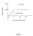
- the frequency response of the hydrophone 202 (FIGS. 3A, 3B) resembles that of a single-pole high pass filter, since it exhibits a single pole and a 6 dB/octave slope at frequencies less than its natural frequency (f n ).
- the amplifier 200 may comprise an operational amplifier.
- the hydrophone may be modeled as a voltage source 202a and a capacitor 202b and resistor 202c in series; the capacitor 202b and the resistors 202c and 204 provide the single pole, and hence the 6 dB/octave slope.
- the natural frequency of the hydrophone 202 depends upon the value of the internal resistance 204 (R i ) of the amplifier 200, the resistance (R H ) of the resistor 202c, and the capacitance (C H ) of the capacitor 202b; this relationship is shown in equation 1.0, below.
- f n 1 2 ⁇ ⁇ ( R H + R i ) C H ⁇ z
- the natural frequency ranges from about 2 to 3 Hz.
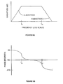
- the frequency response of a typical force-balance accelerometer such as that disclosed in U.S. Pat. No. 5,852,242, issued on 12/22/1998 , the disclosure of which is incorporated herein by reference, resembles an electrical circuit having a differentiating element in combination with a pair of simple lag elements.
- the resulting frequency response exhibits a 6 dB/octave slope at frequencies less than a first cut-off frequency (F c1 ), a substantially flat response between the first cut-off frequency (F c1 ) and a second cut-off frequency (F c2 ), and a - 6dB/octave slope at frequencies greater than the second cut-off frequency (F c2 ).
- the first cut-off frequency (F c1 ) ranges from about 1 to 10 Hz
- the second cut-off frequency (F c2 ) ranges from about 1K to 100K Hz.
- hydrophones and accelerometers have different frequency response characteristics. Accordingly, hydrophones and accelerometers are not naturally suited to eliminate ghost signals 166 across the whole spectrum of desired frequency. To use a hydrophone with an accelerometer advantageously, the frequency response of the hydrophone must match the frequency response of the accelerometer.
- the present invention is directed to overcoming one or more of the limitations of conventional hydrophones.
- a hydrophone assembly that includes a hydrophone and a hydrophone filter coupled to the hydrophone.
- the frequency response of the hydrophone assembly matches the frequency response of an accelerometer.
- an apparatus for measuring seismic waves includes an accelerometer and a hydrophone assembly.
- the hydrophone assembly includes a hydrophone and a hydrophone filter coupled to the hydrophone.
- the frequency response of the hydrophone assembly matches the frequency response of an accelerometer.
- a marine seismic acquisition system includes a seismic source for generating seismic energy, a hydrophone for detecting seismic energy, a hydrophone filter coupled to the hydrophone, an accelerometer for detecting seismic energy, a seismic recorder coupled to the accelerometer and the hydrophone filter, and a controller coupled to the seismic source and seismic recorder for controlling and monitoring the operation of the seismic source and seismic recorder.
- the frequency response of the combination of the hydrophone and hydrophone filter matches the frequency response of the accelerometer.
- a method of providing a hydrophone assembly having a frequency response that matches that of an accelerometer includes filtering the output of the hydrophone with a circuit that provides a differentiator and a pair of simple lags.
- a method of measuring seismic energy using a hydrophone assembly and an accelerometer includes placing the hydrophone assembly and accelerometer in a body of water, generating seismic energy in the body of water, measuring the seismic energy using the hydrophone assembly and the accelerometer, scaling the output of either the accelerometer or hydrophone assembly, and generating an output signal substantially free from surface ghost signals by summing scaled output with the non-scaled output.
- the frequency response of the hydrophone assembly matches the frequency response of the accelerometer.
- a hydrophone and filter assembly for use in a marine seismic acquisition system is provided.
- the hydrophone and filter assembly have a frequency response that closely resembles that of an accelerometer.
- a hydrophone and filter assembly 500 includes a conventional hydrophone 505 and a hydrophone filter 510. As described below, the hydrophone and filter assembly 500 preferably have a frequency response that closely matches the frequency response of a force-balance accelerometer.
- the hydrophone 505 includes a voltage source V H , a capacitor C H , and a resistor R H .
- the hydrophone 505 may comprise any number of conventional commercially available hydrophones such as, for example, Benthos AQ5.
- the hydrophone 505 comprises a model Preseis 2524 available from Input/Output in Stafford, TX in order to optimally provide operation to increased depths.
- the hydrophone filter 510 is coupled to the output 515 of the hydrophone 505.
- the hydrophone filter 510 preferably includes an op amp 520, a resistor R F , a capacitor C F , and a clamp 525.
- the op amp 520 includes a pair of inputs, 530 and 535, and an output 540.
- the first input 530 of the op amp 520 is coupled to the output 515 of the hydrophone 505, the resistor R F , the capacitor C F , and the clamp 525.
- the second input of the op amp 520 is coupled to ground.
- the output 540 of the op amp 520 is coupled to the resistor R F , the capacitor C F , and the clamp 525.
- the output 540 of the op amp 520 is further coupled to the input 545 of a conventional seismic recorder 550.
- the op amp 520 may comprise any number of conventional commercially available op amps such as, for example, Analog Devices AD 824.
- the op amp 520 comprises an OP 134 available from Burr-Brown in order to optimally provide high gain over a wide bandwidth.
- the resistor R F may comprise any number of conventional commercially available resistors such as, for example, KOA, IRC or DALE.
- the resistor R F comprises a model RK73H2A available from KOA having a resistance ranging from about 1050 to 1070 ohms in order to optimally provide a high frequency pole.
- the capacitor C F may comprise any number of conventional commercially available capacitors. In an exemplary embodiment, the capacitor C F is integral to the hydrophone 505.
- the product of the resistance and capacitance of the resistor R F and the capacitor C F provide a high-frequency cut-off of around 20 KHz.
- the clamp 525 functions to limit the excursion of the electrical signals by clipping them off at predetermined levels. In a preferred embodiment, the clamp 525 is selected to clip the electrical signals when their excursion exceeds about 4.0 to 4.5 volts.
- the clamp 525 may comprise any number of conventional commercially available clamping circuits. In an alternative preferred embodiment, the clamp 525 is omitted for circumstances in which excessive signal excursion is not present, or does not present a hazard to the operation of the system.
- the laplace transfer of the transfer function of the hydrophone and filter assembly 500 may be expressed as follows. - R F ⁇ C H ⁇ S ( 1 + R F ⁇ C F ⁇ S ) 1 + R H ⁇ C H ⁇ S
- the hydrophone and filter assembly 500 provides a circuit including a differentiator and a pair of simple lags.
- the corresponding frequency response for the hydrophone and filter assembly 500 is illustrated in FIGS. 6A and 6B.
- the resulting frequency response exhibits a 6 dB/octave slope at frequencies less than a first cut-off frequency (F c1 ), a substantially flat response between the first cut-off frequency (F c1 ) and a second cut-off frequency (F c2 ), and a -6dB/octave slope at frequencies greater than the second cut-off frequency (F c2 ).
- the first cut-off frequency (F c1 ) ranges from about 1K to 1.1K Hz
- the second cut-off frequency (F c2 ) ranges from about 20K to 20.2K Hz in order to optimally detect the acoustic signals generated using typical seismic acquisition systems.
- the hydrophone 505 has a natural frequency of about 2.5 Hz
- the resistor R H has a resistance of about 2.133 M ⁇
- the capacitor C H has a capacitance of about 75 pF.
- These operating parameters provided a first cut-off frequency (F c1 ) of about 15.69 Hz and a second cut-off frequency (F c2 ) of about 6289 Hz.
- the hydrophone 505, hydrophone filter 510, and the seismic recorder 550 are used in a marine seismic acquisition system 700 that further includes a seismic source 705, a controller 710, and an accelerometer 715.
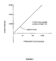
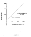
- FIGS. 8, 9 and 10 the frequency response of a geophone, a force-balance accelerometer 715 and a hydrophone 505 including a filter 510 in response to particle motion are illustrated. As shown in FIGS. 9 and 10, the accelerometer 715 and the hydrophone 505 and filter 510 exhibit the same frequency response to particle motion.
- a hydrophone assembly has been described that includes a hydrophone and a hydrophone filter coupled to the hydrophone.
- the frequency response of the hydrophone assembly matches the frequency response of an accelerometer.
- the hydrophone includes a resistor and a capacitor.
- the hydrophone filter includes an operational amplifier, a resistor, and a capacitor.
- the frequency response of the hydrophone assembly matches that of a differentiator in combination with a pair of simple lags.
- the frequency response of the hydrophone assembly exhibits a 6 dB/octave slope for frequencies less than a first cut-off frequency, exhibits a flat response for frequencies between the first cut-off frequency and a second cut-off frequency, and exhibits a -6 dB/octave slope for frequencies greater than the second cut-off frequency.
- An apparatus for measuring seismic waves includes an accelerometer and a hydrophone assembly.
- the hydrophone assembly includes a hydrophone and a hydrophone filter coupled to the hydrophone.
- the frequency response of the hydrophone assembly matches the frequency response of an accelerometer.
- the hydrophone includes a resistor and a capacitor.
- the hydrophone filter includes an operational amplifier, a resistor, and a capacitor.
- the frequency response of the hydrophone assembly matches that of a differentiator in combination with a pair of simple lags.
- the frequency response of the hydrophone assembly exhibits a 6 dB/octave slope for frequencies less than a first cut-off frequency, exhibits a flat response for frequencies between the first cut-off frequency and a second cut-off frequency, and exhibits a -6 dB/octave slope for frequencies greater than the second cut-off frequency.
- a marine seismic acquisition system includes a seismic source for generating seismic energy, a hydrophone for detecting seismic energy, a hydrophone filter coupled to the hydrophone, an accelerometer for detecting seismic energy, a seismic recorder coupled to the accelerometer and the hydrophone filter, and a controller coupled to the seismic source and seismic recorder for controlling and monitoring the operation of the seismic source and seismic recorder.
- the frequency response of the combination of the hydrophone and hydrophone filter matches the frequency response of the accelerometer.
- the hydrophone includes a resistor and a capacitor.
- the hydrophone filter includes an operational amplifier, a resistor, and a capacitor.
- the frequency response of the hydrophone assembly matches that of a differentiator in combination with a pair of simple lags.
- the frequency response of the hydrophone assembly exhibits a 6 dB/octave slope for frequencies less than a first cut-off frequency, exhibits a flat response for frequencies between the first cut-off frequency and a second cut-off frequency, and exhibits a -6 dB/octave slope for frequencies greater than the second cut-off frequency.
- a method of providing a hydrophone assembly having a frequency response that matches that of an accelerometer includes filtering the output of the hydrophone with a circuit that provides a differentiator and a pair of simple lags.
- the frequency response of the hydrophone assembly exhibits a slope of 6dB/octave for frequencies less than a first cut-off frequency, exhibits a flat response for frequencies between the first cut-off frequency and a second cut-off frequency, and exhibits a -6 dB/octave slope for frequencies greater than the second cut-off frequency.
- a method of measuring seismic energy using a hydrophone assembly and an accelerometer includes placing the hydrophone assembly and accelerometer in a body of water, generating seismic energy in the body of water, measuring the seismic energy using the hydrophone assembly and the accelerometer, scaling the output of either the accelerometer or hydrophone assembly, and generating an output signal substantially free from surface ghost signals by summing scaled output with the non-scaled output.
- the frequency response of the hydrophone assembly matches the frequency response of the accelerometer.
- the frequency response of the hydrophone assembly exhibits a slope of 6dB/octave for frequencies less than a first cut-off frequency, exhibits a flat response for frequencies between the first cut-off frequency and a second cut-off frequency, and exhibits a -6 dB/octave slope for frequencies greater than the second cut-off frequency.
Abstract
Description
- The present invention relates to hydrophones employed in seismic exploration. More particularly, the invention relates to an improved hydrophone circuit that provides the frequency response characteristics of an accelerometer.
- Due to the increasing difficulty and cost of finding petroleum resources in the world today, exploration techniques are becoming more and more technologically sophisticated. For example, many have found crystal hydrophones to be useful in petroleum exploration. Basically, hydrophones are used to measure seismic waves created by a source such as an air gun or a dynamite charge, to obtain detailed information about various sub-surface strata of earth.
- As shown in FIG. 1A, a
typical crystal hydrophone 100 includes adiaphragm 102, acrystal 104, and ahousing 106 that is typically filled with agas 107. Thediaphragm 102, which has front andrear sides conductive epoxy 108. Thecrystal 104 is typically made from a material such as Lead Zirconium Titanate, and is silver-plated on its top 104a andbottom 104b to achieve better conductivity. Thecrystal 104 is initially polarized by applying a high-voltage electrical charge to thecrystal 104. When the polarizedcrystal 104 experiences pressure resulting from a physical input such as sound, fluid pressure, or another type of pressure, it produces a voltage representative of the pressure experienced. Thecrystal 104 is electrically connected to electrical output leads 110, 112. To protect thecrystal 104 from contaminants, and to maintain thecrystal 104 in atmospheric pressure, thecrystal 104 and therear side 102b of thediaphragm 102 are sealed within the gas-filledhousing 106. Thehousing 106 protects thecrystal 104 anddiaphragm 102, and facilitates mounting of thehydrophone 100. - The
diaphragm 102 functions to vibrate in response to physical pressures it experiences. The physical deflection of thediaphragm 102 is transferred by theepoxy 108 to thecrystal 104, deforming the electron structure of thecrystal 104 and causing an electrical potential to be provided across theleads - Another apparatus that is also useful in petroleum exploration is the accelerometer. Accelerometers are commonly used to measure the motion of the earth's surface in response to seismic waves created by a seismic source, to obtain detailed information about various sub-surface strata in the earth.
- As mentioned above, hydrophones and accelerometers are often used in petroleum exploration in conjunction with seismic equipment. In one example of such an application (FIG. 1B), a
cable 150 including one or more hydrophones and one or more accelerometers is placed on thesea floor 154. Such a cable may be made up ofcylindrical units 152, where eachunit 152 includes a geophone and an accelerometer. - Seismic waves are produced by a
seismic source 156 that is towed behind aship 158; theseismic source 156 may comprise an air gun, a dynamite charge, or the like. Theseismic source 156 produces a large explosion, creatingseismic waves 160. Theseismic waves 160 travel throughwater 162 and various layers ofearth 164, and are reflected back to thecable 150 as upgoingincident waves 161. Eachunit 152 detects and measures theincident waves 161 and creates a real-time record of the results. This record is typically stored in a recorder (not shown) that is linked to or contained within thecable 150. Records of this nature help geologists determine the makeup of theearth 164. - One problem with this arrangement, however, is
surface ghost signals 166.Surface ghost signals 166 are produced byincident waves 161 that are reflected from the water'ssurface 168. At the wavelengths typically used for seismic signals, thesurface 168 provides an effective mirror to reflectincident waves 161 and create downgoingsurface ghost signals 166.Surface ghost signals 166 contain no additional information regarding the composition of theearth 164 or the possible petroleum deposits therein, and they interfere with the proper receipt and interpretation of theincident waves 161. Accordingly, it is desirable to eliminate the errors introduced by thesurface ghost signals 166. - A hydrophone-accelerometer combination, in theory, is naturally suited to eliminate surface ghost signals. Generally, hydrophones detect pressure omnidirectionally, and accelerometers detect force or acceleration, which is directional. Due to the relative strengths of the
incident waves 161 and thesurface ghost signals 166 at different depths, a hydrophone's output and an accelerometer's output will both vary with depth. For aseismic wave 161 of a given magnitude and frequency, a hydrophone's output will vary with depth sinusoidally (curve 180, FIG. 1C). Likewise, for the givenseismic wave 161, an accelerometer's output will vary sinusoidally with depth (curve 182, FIG. 1C). The hydrophone and accelerometer outputs may be scaled by external circuitry or by a mathematical algorithm in a computer, so that their peak values have the same amplitude; for example, in FIG. 1C, the hydrophone and accelerometer outputs are scaled to a maximum peak amplitude of 1 and a minimum peak amplitude of-1. After such scaling, the sum of the hydrophone and accelerometer outputs will always be 1, irrespective of the depth at which the hydrophone and accelerometer are both located (curve 184, FIG. 1C). Therefore, in theory, a hydrophone output and an accelerometer output may be combined to effectively eliminate the influence ofsurface ghost signals 166. - One problem in applying this theory is that the frequency responses of hydrophones and accelerometers differ. Therefore, the hydrophone and accelerometer outputs will only complement each other as shown in FIG. 1C when the
seismic wave 160 has a certain frequency. As a result, if the frequency of theseismic wave 160 were to change, the combined hydrophone-accelerometer output 184 would no longer be constant. - The difference between frequency responses of hydrophones and accelerometers will now be explained with reference to FIGS. 2-4B. When an electronic amplifier 200 (FIG. 2) is utilized to amplify the output of a
typical hydrophone 202, the frequency response of the hydrophone 202 (FIGS. 3A, 3B) resembles that of a single-pole high pass filter, since it exhibits a single pole and a 6 dB/octave slope at frequencies less than its natural frequency (fn). Theamplifier 200 may comprise an operational amplifier. The hydrophone may be modeled as a voltage source 202a and a capacitor 202b and resistor 202c in series; the capacitor 202b and theresistors 202c and 204 provide the single pole, and hence the 6 dB/octave slope. The natural frequency of thehydrophone 202 depends upon the value of the internal resistance 204 (Ri) of theamplifier 200, the resistance (RH) of the resistor 202c, and the capacitance (CH) of the capacitor 202b; this relationship is shown in equation 1.0, below.
- For typical hydrophones, the natural frequency ranges from about 2 to 3 Hz.
- In contrast to the
hydrophone 202, as illustrated in FIGS. 4A and 4B, the frequency response of a typical force-balance accelerometer, such as that disclosed inU.S. Pat. No. 5,852,242, issued on 12/22/1998 , the disclosure of which is incorporated herein by reference, resembles an electrical circuit having a differentiating element in combination with a pair of simple lag elements. The resulting frequency response exhibits a 6 dB/octave slope at frequencies less than a first cut-off frequency (Fc1), a substantially flat response between the first cut-off frequency (Fc1) and a second cut-off frequency (Fc2), and a - 6dB/octave slope at frequencies greater than the second cut-off frequency (Fc2). For typical force-balance accelerometers, the first cut-off frequency (Fc1) ranges from about 1 to 10 Hz, and the second cut-off frequency (Fc2) ranges from about 1K to 100K Hz. - For the reasons explained above, hydrophones and accelerometers have different frequency response characteristics. Accordingly, hydrophones and accelerometers are not naturally suited to eliminate
ghost signals 166 across the whole spectrum of desired frequency. To use a hydrophone with an accelerometer advantageously, the frequency response of the hydrophone must match the frequency response of the accelerometer. - The present invention is directed to overcoming one or more of the limitations of conventional hydrophones.
- According to one aspect of the present invention, a hydrophone assembly is provided that includes a hydrophone and a hydrophone filter coupled to the hydrophone. The frequency response of the hydrophone assembly matches the frequency response of an accelerometer.
- According to another aspect of the present invention, an apparatus for measuring seismic waves is provided that includes an accelerometer and a hydrophone assembly. The hydrophone assembly includes a hydrophone and a hydrophone filter coupled to the hydrophone. The frequency response of the hydrophone assembly matches the frequency response of an accelerometer.
- According to another aspect of the present invention, a marine seismic acquisition system is provided that includes a seismic source for generating seismic energy, a hydrophone for detecting seismic energy, a hydrophone filter coupled to the hydrophone, an accelerometer for detecting seismic energy, a seismic recorder coupled to the accelerometer and the hydrophone filter, and a controller coupled to the seismic source and seismic recorder for controlling and monitoring the operation of the seismic source and seismic recorder. The frequency response of the combination of the hydrophone and hydrophone filter matches the frequency response of the accelerometer.
- According to another aspect of the present invention, a method of providing a hydrophone assembly having a frequency response that matches that of an accelerometer is provided that includes filtering the output of the hydrophone with a circuit that provides a differentiator and a pair of simple lags.
- According to another aspect of the present invention, a method of measuring seismic energy using a hydrophone assembly and an accelerometer is provided that includes placing the hydrophone assembly and accelerometer in a body of water, generating seismic energy in the body of water, measuring the seismic energy using the hydrophone assembly and the accelerometer, scaling the output of either the accelerometer or hydrophone assembly, and generating an output signal substantially free from surface ghost signals by summing scaled output with the non-scaled output. The frequency response of the hydrophone assembly matches the frequency response of the accelerometer.
-
- FIG. 1A is a cross-sectional side view of a typical hydrophone.
- FIG. 1B is an illustration of the use of a ocean bottom cable in conjunction with seismic equipment for petroleum exploration.
- FIG. 1C is a graphical illustration of the use of the output of a hydrophone and an accelerometer to negate the influence of surface ghost signals.
- FIG. 2 is an electrical schematic model of a hydrophone-amplifier.
- FIG. 3A is a graphical illustration of the frequency response (magnitude) of a hydrophone coupled to an amplifier.
- FIG. 3B is a graphical illustration of the frequency response (phase) of a hydrophone coupled to an amplifier.
- FIG. 4A is a graphical illustration of the frequency response (magnitude) of a typical force-balance accelerometer.
- FIG. 4B is a graphical illustration of the frequency response (phase) of a typical force-balance accelerometer.
- FIG. 5 is a schematic illustration of an embodiment of a hydrophone including a filter.
- FIG. 6A is a graphical illustration of the frequency response (magnitude) of the hydrophone and filter of FIG. 5.
- FIG. 6B is a graphical illustration of the frequency response (phase) of a hydrophone and filter of FIG. 5.
- FIG. 7 is a schematic illustration of a marine seismic acquisition system.
- FIG. 8 is an illustration of the frequency response of an exemplary embodiment of a geophone to particle motion.
- FIG. 9 is an illustration of the frequency response of an exemplary embodiment of a force-balance accelerometer to particle motion.
- FIG. 10 is an illustration of the frequency response of an exemplary embodiment of a hydrophone with a filter to particle motion.
- A hydrophone and filter assembly for use in a marine seismic acquisition system is provided. The hydrophone and filter assembly have a frequency response that closely resembles that of an accelerometer.
- Referring to FIG. 5, a hydrophone and
filter assembly 500 includes aconventional hydrophone 505 and ahydrophone filter 510. As described below, the hydrophone andfilter assembly 500 preferably have a frequency response that closely matches the frequency response of a force-balance accelerometer. - The
hydrophone 505 includes a voltage source VH, a capacitor CH, and a resistor RH. Thehydrophone 505 may comprise any number of conventional commercially available hydrophones such as, for example, Benthos AQ5. In a preferred embodiment, thehydrophone 505 comprises a model Preseis 2524 available from Input/Output in Stafford, TX in order to optimally provide operation to increased depths. - The
hydrophone filter 510 is coupled to theoutput 515 of thehydrophone 505. Thehydrophone filter 510 preferably includes anop amp 520, a resistor RF, a capacitor CF, and aclamp 525. Theop amp 520 includes a pair of inputs, 530 and 535, and anoutput 540. Thefirst input 530 of theop amp 520 is coupled to theoutput 515 of thehydrophone 505, the resistor RF, the capacitor CF, and theclamp 525. The second input of theop amp 520 is coupled to ground. Theoutput 540 of theop amp 520 is coupled to the resistor RF, the capacitor CF, and theclamp 525. In a preferred embodiment, theoutput 540 of theop amp 520 is further coupled to theinput 545 of a conventionalseismic recorder 550. - The
op amp 520 may comprise any number of conventional commercially available op amps such as, for example, Analog Devices AD 824. In a preferred embodiment, theop amp 520 comprises an OP 134 available from Burr-Brown in order to optimally provide high gain over a wide bandwidth. - The resistor RF may comprise any number of conventional commercially available resistors such as, for example, KOA, IRC or DALE. In a preferred embodiment, the resistor RF comprises a model RK73H2A available from KOA having a resistance ranging from about 1050 to 1070 ohms in order to optimally provide a high frequency pole.
- The capacitor CF may comprise any number of conventional commercially available capacitors. In an exemplary embodiment, the capacitor CF is integral to the
hydrophone 505. - In a particularly preferred embodiment, the product of the resistance and capacitance of the resistor RF and the capacitor CF provide a high-frequency cut-off of around 20 KHz.
- The
clamp 525 functions to limit the excursion of the electrical signals by clipping them off at predetermined levels. In a preferred embodiment, theclamp 525 is selected to clip the electrical signals when their excursion exceeds about 4.0 to 4.5 volts. Theclamp 525 may comprise any number of conventional commercially available clamping circuits. In an alternative preferred embodiment, theclamp 525 is omitted for circumstances in which excessive signal excursion is not present, or does not present a hazard to the operation of the system. - The laplace transfer of the transfer function of the hydrophone and
filter assembly 500 may be expressed as follows.
- Thus, the hydrophone and
filter assembly 500 provides a circuit including a differentiator and a pair of simple lags. The corresponding frequency response for the hydrophone andfilter assembly 500 is illustrated in FIGS. 6A and 6B. The resulting frequency response exhibits a 6 dB/octave slope at frequencies less than a first cut-off frequency (Fc1), a substantially flat response between the first cut-off frequency (Fc1) and a second cut-off frequency (Fc2), and a -6dB/octave slope at frequencies greater than the second cut-off frequency (Fc2). In a preferred embodiment, the first cut-off frequency (Fc1) ranges from about 1K to 1.1K Hz, and the second cut-off frequency (Fc2) ranges from about 20K to 20.2K Hz in order to optimally detect the acoustic signals generated using typical seismic acquisition systems. - In an exemplary embodiment, the
hydrophone 505 has a natural frequency of about 2.5 Hz, the resistor RH has a resistance of about 2.133 MΩ, and the capacitor CH has a capacitance of about 75 pF. These operating parameters provided a first cut-off frequency (Fc1) of about 15.69 Hz and a second cut-off frequency (Fc2) of about 6289 Hz. - Referring now to FIG. 7, in a preferred embodiment, the
hydrophone 505,hydrophone filter 510, and theseismic recorder 550 are used in a marineseismic acquisition system 700 that further includes aseismic source 705, acontroller 710, and anaccelerometer 715. - Referring now to FIGS. 8, 9 and 10, the frequency response of a geophone, a force-
balance accelerometer 715 and ahydrophone 505 including afilter 510 in response to particle motion are illustrated. As shown in FIGS. 9 and 10, theaccelerometer 715 and thehydrophone 505 and filter 510 exhibit the same frequency response to particle motion. - A hydrophone assembly has been described that includes a hydrophone and a hydrophone filter coupled to the hydrophone. The frequency response of the hydrophone assembly matches the frequency response of an accelerometer. In a preferred embodiment, the hydrophone includes a resistor and a capacitor. In a preferred embodiment, the hydrophone filter includes an operational amplifier, a resistor, and a capacitor. In a preferred embodiment, the frequency response of the hydrophone assembly matches that of a differentiator in combination with a pair of simple lags. In a preferred embodiment, the frequency response of the hydrophone assembly exhibits a 6 dB/octave slope for frequencies less than a first cut-off frequency, exhibits a flat response for frequencies between the first cut-off frequency and a second cut-off frequency, and exhibits a -6 dB/octave slope for frequencies greater than the second cut-off frequency.
- An apparatus for measuring seismic waves has also been described that includes an accelerometer and a hydrophone assembly. The hydrophone assembly includes a hydrophone and a hydrophone filter coupled to the hydrophone. The frequency response of the hydrophone assembly matches the frequency response of an accelerometer. In a preferred embodiment, the hydrophone includes a resistor and a capacitor. In a preferred embodiment, the hydrophone filter includes an operational amplifier, a resistor, and a capacitor. In a preferred embodiment, the frequency response of the hydrophone assembly matches that of a differentiator in combination with a pair of simple lags. In a preferred embodiment, the frequency response of the hydrophone assembly exhibits a 6 dB/octave slope for frequencies less than a first cut-off frequency, exhibits a flat response for frequencies between the first cut-off frequency and a second cut-off frequency, and exhibits a -6 dB/octave slope for frequencies greater than the second cut-off frequency.
- A marine seismic acquisition system has been described that includes a seismic source for generating seismic energy, a hydrophone for detecting seismic energy, a hydrophone filter coupled to the hydrophone, an accelerometer for detecting seismic energy, a seismic recorder coupled to the accelerometer and the hydrophone filter, and a controller coupled to the seismic source and seismic recorder for controlling and monitoring the operation of the seismic source and seismic recorder. The frequency response of the combination of the hydrophone and hydrophone filter matches the frequency response of the accelerometer. In a preferred embodiment, the hydrophone includes a resistor and a capacitor. In a preferred embodiment, the hydrophone filter includes an operational amplifier, a resistor, and a capacitor. In a preferred embodiment, the frequency response of the hydrophone assembly matches that of a differentiator in combination with a pair of simple lags. In a preferred embodiment, the frequency response of the hydrophone assembly exhibits a 6 dB/octave slope for frequencies less than a first cut-off frequency, exhibits a flat response for frequencies between the first cut-off frequency and a second cut-off frequency, and exhibits a -6 dB/octave slope for frequencies greater than the second cut-off frequency.
- A method of providing a hydrophone assembly having a frequency response that matches that of an accelerometer has been described that includes filtering the output of the hydrophone with a circuit that provides a differentiator and a pair of simple lags. In a preferred embodiment, the frequency response of the hydrophone assembly exhibits a slope of 6dB/octave for frequencies less than a first cut-off frequency, exhibits a flat response for frequencies between the first cut-off frequency and a second cut-off frequency, and exhibits a -6 dB/octave slope for frequencies greater than the second cut-off frequency.
- A method of measuring seismic energy using a hydrophone assembly and an accelerometer has been described that includes placing the hydrophone assembly and accelerometer in a body of water, generating seismic energy in the body of water, measuring the seismic energy using the hydrophone assembly and the accelerometer, scaling the output of either the accelerometer or hydrophone assembly, and generating an output signal substantially free from surface ghost signals by summing scaled output with the non-scaled output. The frequency response of the hydrophone assembly matches the frequency response of the accelerometer. In a preferred embodiment, the frequency response of the hydrophone assembly exhibits a slope of 6dB/octave for frequencies less than a first cut-off frequency, exhibits a flat response for frequencies between the first cut-off frequency and a second cut-off frequency, and exhibits a -6 dB/octave slope for frequencies greater than the second cut-off frequency.
- Although illustrative embodiments of the invention have been shown and described, a wide range of modification, changes and substitution is contemplated in the foregoing disclosure. In some instances, some features of the present invention may be employed without a corresponding use of the other features. Accordingly, it is appropriate that the appended claims be construed broadly and in a manner consistent with the scope of the invention.
Claims (12)
- An apparatus for detecting seismic energy, comprising:(a) a hydrophone;(b) an accelerometer;(c) a hydrophone filter coupled to the hydrophone to closely match a frequency response of the hydrophone assembly to a frequency response of an accelerometer, the filter having a circuit including a differentiator and a pair of lags.
- The apparatus of claim 1, wherein the accelerometer is a force balance accelerometer.
- The apparatus of claim 1, wherein a laplace transfer of a transfer function of the hydrophone and hydrophone filter is expressed as (-RFCHs)/(1+ RFCFs)(1+ RHCHs).
- The apparatus of claim 1 wherein the hydrophone filter includes:(i) a resistor;(ii) a capacitor, and(iii) an op amp having a first and second input and an output; the first input being coupled to an output of the hydrophone, the resistor and the capacitor, the second input being coupled to a ground, and the output being coupled to the resistor and the capacitor.
- The apparatus of claim 4, further comprising a clamp being coupled to the first input of the op amp and the output of the op amp.
- The apparatus of claim 4 further comprising a seismic recorder coupled to the output of the op amp.
- A method for detecting seismic energy, comprising:(a) using a hydrophone for detecting seismic energy;(b) using an accelerometer for detecting seismic energy;(c) filtering the output of the hydrophone with a circuit that provides a differentiator and a pair of lags to closely match a frequency response of the hydrophone assembly to a frequency response of an accelerometer.
- The method of claim 7, wherein the accelerometer is a force balance accelerometer.
- The method of claim 7, further comprising expressing a laplace transfer of a transfer function of the hydrophone and hydrophone filter as (-RFCHs)/(1+ RFCFs)(1+ RHCHs).
- The method of claim 7 wherein the hydrophone filter includes:(i) a resistor;(ii) a capacitor, and(iii) an op amp having a first and second input and an output; the first input being coupled to an output of the hydrophone, the resistor and the capacitor, the second input being coupled to a ground, and the output being coupled to the resistor and the capacitor.
- The method of claim 10, further comprising coupling a clamp to the first input of the op amp and the output of the op amp.
- The method of claim 10 further comprising recording seismic data using a seismic recorder coupled to the output of the op amp.
Applications Claiming Priority (2)
| Application Number | Priority Date | Filing Date | Title |
|---|---|---|---|
| US12507699P | 1999-03-17 | 1999-03-17 | |
| EP00916159A EP1183555A4 (en) | 1999-03-17 | 2000-03-08 | Hydrophone assembly |
Related Parent Applications (2)
| Application Number | Title | Priority Date | Filing Date |
|---|---|---|---|
| EP00916159.7 Division | 2000-03-08 | ||
| EP00916159A Division EP1183555A4 (en) | 1999-03-17 | 2000-03-08 | Hydrophone assembly |
Publications (3)
| Publication Number | Publication Date |
|---|---|
| EP1847850A2 true EP1847850A2 (en) | 2007-10-24 |
| EP1847850A3 EP1847850A3 (en) | 2010-06-16 |
| EP1847850B1 EP1847850B1 (en) | 2013-04-24 |
Family
ID=22418086
Family Applications (11)
| Application Number | Title | Priority Date | Filing Date |
|---|---|---|---|
| EP20070012105 Expired - Lifetime EP1847850B1 (en) | 1999-03-17 | 2000-03-08 | Hydrophone assembly |
| EP00916159A Withdrawn EP1183555A4 (en) | 1999-03-17 | 2000-03-08 | Hydrophone assembly |
| EP00913804A Withdrawn EP1169657A4 (en) | 1999-03-17 | 2000-03-08 | Calibration of sensors |
| EP00914976A Expired - Lifetime EP1169896B8 (en) | 1999-03-17 | 2000-03-15 | Low stress die attachment |
| EP06005170.3A Expired - Lifetime EP1674873B1 (en) | 1999-03-17 | 2000-03-16 | Sensor |
| EP00926518A Ceased EP1208385A4 (en) | 1999-03-17 | 2000-03-16 | Sensor design and process |
| EP20000916403 Expired - Lifetime EP1175628B1 (en) | 1999-03-17 | 2000-03-16 | Accelerometer transducer used for seismic recording |
| EP00918544A Expired - Lifetime EP1177451B1 (en) | 1999-03-17 | 2000-03-16 | Method for measuring acceleration with a plurality of operating modes |
| EP20110171126 Withdrawn EP2410344A3 (en) | 1999-03-17 | 2000-03-16 | Method for manufacturing an accelerometer |
| EP20060012101 Withdrawn EP1705489A3 (en) | 1999-03-17 | 2000-03-16 | Sensor design and process |
| EP20000915012 Expired - Lifetime EP1192419B1 (en) | 1999-03-17 | 2000-03-17 | Integrated and multi-axis sensor assembly and packaging |
Family Applications After (10)
| Application Number | Title | Priority Date | Filing Date |
|---|---|---|---|
| EP00916159A Withdrawn EP1183555A4 (en) | 1999-03-17 | 2000-03-08 | Hydrophone assembly |
| EP00913804A Withdrawn EP1169657A4 (en) | 1999-03-17 | 2000-03-08 | Calibration of sensors |
| EP00914976A Expired - Lifetime EP1169896B8 (en) | 1999-03-17 | 2000-03-15 | Low stress die attachment |
| EP06005170.3A Expired - Lifetime EP1674873B1 (en) | 1999-03-17 | 2000-03-16 | Sensor |
| EP00926518A Ceased EP1208385A4 (en) | 1999-03-17 | 2000-03-16 | Sensor design and process |
| EP20000916403 Expired - Lifetime EP1175628B1 (en) | 1999-03-17 | 2000-03-16 | Accelerometer transducer used for seismic recording |
| EP00918544A Expired - Lifetime EP1177451B1 (en) | 1999-03-17 | 2000-03-16 | Method for measuring acceleration with a plurality of operating modes |
| EP20110171126 Withdrawn EP2410344A3 (en) | 1999-03-17 | 2000-03-16 | Method for manufacturing an accelerometer |
| EP20060012101 Withdrawn EP1705489A3 (en) | 1999-03-17 | 2000-03-16 | Sensor design and process |
| EP20000915012 Expired - Lifetime EP1192419B1 (en) | 1999-03-17 | 2000-03-17 | Integrated and multi-axis sensor assembly and packaging |
Country Status (9)
| Country | Link |
|---|---|
| US (2) | US6861587B1 (en) |
| EP (11) | EP1847850B1 (en) |
| JP (5) | JP5420127B2 (en) |
| AT (3) | ATE355728T1 (en) |
| AU (8) | AU3517600A (en) |
| CA (7) | CA2365886A1 (en) |
| DE (4) | DE60033643T2 (en) |
| NO (7) | NO335756B1 (en) |
| WO (8) | WO2000055652A1 (en) |
Cited By (2)
| Publication number | Priority date | Publication date | Assignee | Title |
|---|---|---|---|---|
| US9664805B2 (en) | 2012-03-08 | 2017-05-30 | Shell Oil Company | Seismic cable handling system and method |
| US10705232B2 (en) | 2012-03-08 | 2020-07-07 | Shell Oil Company | Integrated seismic monitoring system and method |
Families Citing this family (87)
| Publication number | Priority date | Publication date | Assignee | Title |
|---|---|---|---|---|
| US20040105533A1 (en) * | 1998-08-07 | 2004-06-03 | Input/Output, Inc. | Single station wireless seismic data acquisition method and apparatus |
| US6725164B1 (en) | 1999-03-17 | 2004-04-20 | Input/Output, Inc. | Hydrophone assembly |
| US6347594B1 (en) * | 2000-01-28 | 2002-02-19 | Deere & Company | Narrow profile opener capable of high speed operation |
| JP2002257847A (en) * | 2001-02-28 | 2002-09-11 | Matsushita Electric Ind Co Ltd | Accelerometer |
| US6814179B2 (en) * | 2001-05-25 | 2004-11-09 | Input/Output, Inc. | Seismic sensing apparatus and method with high-g shock isolation |
| US7870788B2 (en) * | 2002-01-25 | 2011-01-18 | Kinemetrics, Inc. | Fabrication process and package design for use in a micro-machined seismometer or other device |
| GB2395305B (en) * | 2002-11-15 | 2006-03-22 | Westerngeco Seismic Holdings | Processing seismic data |
| US20040145613A1 (en) * | 2003-01-29 | 2004-07-29 | Stavely Donald J. | User Interface using acceleration for input |
| WO2004086094A1 (en) * | 2003-03-26 | 2004-10-07 | Westergeco Seismic Holdings Limited | Processing seismic data representative of the acceleration wavefield |
| DE10322278B4 (en) * | 2003-05-16 | 2014-06-18 | Endress + Hauser Conducta Gesellschaft für Mess- und Regeltechnik mbH + Co. KG | Sensor simulator for testing transducers |
| US7310287B2 (en) | 2003-05-30 | 2007-12-18 | Fairfield Industries Incorporated | Method and apparatus for seismic data acquisition |
| US8228759B2 (en) | 2003-11-21 | 2012-07-24 | Fairfield Industries Incorporated | System for transmission of seismic data |
| US7124028B2 (en) | 2003-11-21 | 2006-10-17 | Fairfield Industries, Inc. | Method and system for transmission of seismic data |
| US7225662B2 (en) | 2004-08-27 | 2007-06-05 | Schlumberger Technology Corporation | Geophone calibration technique |
| US20060133202A1 (en) * | 2004-12-22 | 2006-06-22 | Tenghamn Stig R L | Motion sensors in a marine seismic streamer |
| US7026547B1 (en) * | 2005-01-21 | 2006-04-11 | Infineon Technologies Ag | Semiconductor device and a method for fabricating a semiconductor device |
| JP2006214898A (en) * | 2005-02-04 | 2006-08-17 | Seiko Epson Corp | Piezo-electric device and electronic equipment |
| WO2006127776A1 (en) * | 2005-05-25 | 2006-11-30 | Northrop Grumman Corporation | Metal electrodes for elimination of spurious charge effects in accelerometers and other mems devices |
| US7243544B2 (en) * | 2005-06-16 | 2007-07-17 | Honeywell International Inc. | Passive and wireless acoustic wave accelerometer |
| US20070079656A1 (en) * | 2005-10-11 | 2007-04-12 | Honeywell International Inc. | Micro-machined acoustic wave accelerometer |
| JP2007127607A (en) * | 2005-11-07 | 2007-05-24 | Mitsutoyo Corp | Sensor block |
| GB2478691B (en) * | 2006-04-13 | 2011-10-26 | Tiax Llc | An Orientation Sensor Error Reduction Method |
| US7366055B2 (en) * | 2006-05-05 | 2008-04-29 | Optoplan As | Ocean bottom seismic sensing system |
| US8064286B2 (en) * | 2006-05-05 | 2011-11-22 | Optoplan As | Seismic streamer array |
| DE102006030616A1 (en) | 2006-07-03 | 2008-01-17 | Valeo Schalter Und Sensoren Gmbh | Interface device |
| DE102007013413A1 (en) * | 2007-03-20 | 2008-10-09 | GeoForschungsZentrum Potsdam Stiftung des öffentlichen Rechts | Seismic source with adaptive control and corresponding method |
| US8136383B2 (en) * | 2007-08-28 | 2012-03-20 | Westerngeco L.L.C. | Calibrating an accelerometer |
| US8605543B2 (en) * | 2007-09-21 | 2013-12-10 | Fairfield Industries Incorporated | Method and apparatus for correcting the timing function in a nodal seismic data acquisition unit |
| CA2700280C (en) | 2008-11-04 | 2018-05-08 | Fairfield Industries, Inc. | Method and apparatus for correcting the timing function in a nodal seismic data acquisition unit |
| US20090206548A1 (en) * | 2008-02-15 | 2009-08-20 | Scott Allan Hawkins | Protective game piece cover and faceplates |
| CN103064109B (en) * | 2008-11-04 | 2017-07-18 | 费尔菲尔德工业公司 | Method and apparatus for correcting the clocking capability in nodal seismic data acquisition unit |
| US8131494B2 (en) * | 2008-12-04 | 2012-03-06 | Baker Hughes Incorporated | Rotatable orientation independent gravity sensor and methods for correcting systematic errors |
| US8117888B2 (en) * | 2009-02-11 | 2012-02-21 | Perception Digital Limited | Method and apparatus of improving accuracy of accelerometer |
| US8514655B2 (en) * | 2009-11-12 | 2013-08-20 | Schlumberger Technology Corporation | Method and apparatus for measuring a hydrophone parameter |
| JP2011112392A (en) * | 2009-11-24 | 2011-06-09 | Panasonic Electric Works Co Ltd | Acceleration sensor |
| JP2011112390A (en) * | 2009-11-24 | 2011-06-09 | Panasonic Electric Works Co Ltd | Acceleration sensor |
| CN102667497B (en) | 2009-11-24 | 2014-06-18 | 松下电器产业株式会社 | Acceleration sensor |
| US8614928B2 (en) * | 2009-12-31 | 2013-12-24 | Wireless Seismic, Inc. | Wireless data acquisition system and method using self-initializing wireless modules |
| US20120002504A1 (en) * | 2010-03-01 | 2012-01-05 | Everhard Muyzert | Gravity measurements in marine, land and/or seabed seismic applications |
| US9297923B2 (en) * | 2010-03-01 | 2016-03-29 | Westerngeco L.L.C. | Gravity measurements using seismic streamers |
| JPWO2011111540A1 (en) * | 2010-03-08 | 2013-06-27 | アルプス電気株式会社 | Physical quantity sensor |
| WO2011111539A1 (en) * | 2010-03-08 | 2011-09-15 | アルプス電気株式会社 | Physical quantity sensor |
| CN101793524B (en) * | 2010-03-26 | 2012-05-30 | 中北大学 | Method for solving vehicle-mounted MIMU output information |
| US9010170B2 (en) * | 2010-08-16 | 2015-04-21 | Westerngeco L.L.C. | Method and apparatus to test an accelerometer |
| US9217805B2 (en) | 2010-10-01 | 2015-12-22 | Westerngeco L.L.C. | Monitoring the quality of particle motion data during a seismic acquisition |
| US8639442B2 (en) | 2010-11-23 | 2014-01-28 | Westerngeco L.L.C. | Identifying invalid seismic data |
| RU2603438C2 (en) * | 2011-02-07 | 2016-11-27 | Ион Джиофизикал Корпорейшн | Method and device for underwater signals detecting |
| US8843345B2 (en) * | 2011-06-20 | 2014-09-23 | Invensense, Inc. | Motion determination |
| WO2013002809A1 (en) * | 2011-06-30 | 2013-01-03 | Hewlett-Packard Development Company, L.P. | Calibration of mems sensor |
| US8577640B2 (en) | 2011-08-17 | 2013-11-05 | Invensense, Inc. | Magnetometer bias and anomaly detector |
| US9683865B2 (en) | 2012-01-26 | 2017-06-20 | Invensense, Inc. | In-use automatic calibration methodology for sensors in mobile devices |
| DE102012014407A1 (en) * | 2012-07-19 | 2014-01-23 | Wabco Gmbh | Device for detecting and processing sensor measured values and / or for controlling actuators |
| EP2690468B1 (en) * | 2012-07-27 | 2019-03-27 | Sercel | A streamer for seismic prospection comprising tilt compensation of directional sensors |
| CN102830251B (en) * | 2012-09-04 | 2013-12-18 | 中国兵器工业集团第二一四研究所苏州研发中心 | Online evaluation method for performance parameter of wafer-level single-pivot capacitive accelerometer |
| US9321630B2 (en) * | 2013-02-20 | 2016-04-26 | Pgs Geophysical As | Sensor with vacuum-sealed cavity |
| US9400337B2 (en) | 2013-03-15 | 2016-07-26 | L-3 Communications Corporation | Beam accelerometer |
| CN103278846B (en) * | 2013-06-03 | 2018-03-02 | 北京京援伟达技术有限公司 | Microseismograph, microseismic signals collection denoising method and microseismic signals acquisition method |
| WO2015042700A1 (en) | 2013-09-24 | 2015-04-02 | Motion Engine Inc. | Mems components and method of wafer-level manufacturing thereof |
| EP3028007A4 (en) | 2013-08-02 | 2017-07-12 | Motion Engine Inc. | Mems motion sensor and method of manufacturing |
| US20160229684A1 (en) * | 2013-09-24 | 2016-08-11 | Motion Engine Inc. | Mems device including support structure and method of manufacturing |
| US9772220B1 (en) | 2013-12-06 | 2017-09-26 | Harris Corporation | Hydrophone |
| DE102013114140A1 (en) * | 2013-12-16 | 2015-06-18 | Endress + Hauser Wetzer Gmbh + Co. Kg | Sensor housing and sensor arrangement with a sensor housing |
| AU2014375216B2 (en) * | 2013-12-30 | 2019-12-12 | Pgs Geophysical As | Control system for marine vibrators operating near impulsive seismic signal sources |
| JP6590812B2 (en) | 2014-01-09 | 2019-10-16 | モーション・エンジン・インコーポレーテッド | Integrated MEMS system |
| EP2902809B1 (en) * | 2014-01-31 | 2022-04-13 | Draka Elevator Products, Inc. | Seismic-detection sensor device for vertical transportation equipment |
| CN103852784B (en) * | 2014-03-12 | 2016-12-07 | 北京矿冶研究总院 | Method for improving signal-to-noise ratio of mine microseismic detector |
| US20170030788A1 (en) | 2014-04-10 | 2017-02-02 | Motion Engine Inc. | Mems pressure sensor |
| US11674803B2 (en) | 2014-06-02 | 2023-06-13 | Motion Engine, Inc. | Multi-mass MEMS motion sensor |
| WO2016003451A1 (en) * | 2014-07-02 | 2016-01-07 | The Johns Hopkins University | Photodetection circuit and operating method thereof |
| CN105319597B (en) * | 2014-07-31 | 2018-05-08 | 中国石油化工股份有限公司 | Seismic receiver system data recording method in a kind of well |
| WO2016090467A1 (en) | 2014-12-09 | 2016-06-16 | Motion Engine Inc. | 3d mems magnetometer and associated methods |
| EP3245543B1 (en) | 2015-01-14 | 2021-04-28 | ION Geophysical Corporation | Ocean sensor system |
| US10407299B2 (en) | 2015-01-15 | 2019-09-10 | Motion Engine Inc. | 3D MEMS device with hermetic cavity |
| DE102015103485A1 (en) * | 2015-03-10 | 2016-09-15 | Endress + Hauser Gmbh + Co. Kg | MEMS sensor, esp. Pressure sensor |
| AU2016344004A1 (en) | 2015-10-30 | 2018-06-14 | Ion Geophysical Corporation | Multi-axis, single mass accelerometer |
| US10161956B2 (en) | 2016-04-25 | 2018-12-25 | Honeywell International Inc. | Reducing bias in an accelerometer via a pole piece |
| BR112019000670B1 (en) | 2016-07-12 | 2023-01-24 | Bp Exploration Operating Company Limited | SYSTEM FOR ACQUISITION AND PROCESSING SEISMIC DATA, METHOD FOR PROCESSING SEISMIC DATA PERFORMED BY A SEISMIC DATA SYSTEM, AND METHOD FOR PROCESSING SEISMIC DATA |
| TWI639810B (en) * | 2017-09-20 | 2018-11-01 | 和碩聯合科技股份有限公司 | Calibration method of gravity sensor |
| CN109669055B (en) * | 2017-10-13 | 2021-04-27 | 航天科工惯性技术有限公司 | Vibration rectification error test acquisition circuit and acquisition system with same |
| CN108168774B (en) * | 2017-12-27 | 2020-01-14 | 中国航发四川燃气涡轮研究院 | Space vector force calibration method |
| TWI670475B (en) * | 2018-04-11 | 2019-09-01 | 逸奇科技股份有限公司 | Multi-axis load cell and manufacturing method thereof |
| DE102018211755A1 (en) * | 2018-07-13 | 2020-01-16 | Infineon Technologies Ag | AMPLITUDE DETECTION, AMPLITUDE CONTROL AND DIRECTION DETECTION OF A VIBRATION OF A VIBRATION BODY |
| GB2575694A (en) * | 2018-07-20 | 2020-01-22 | Atlantic Inertial Systems Ltd | Sensor packages |
| WO2020056216A1 (en) * | 2018-09-13 | 2020-03-19 | Ion Geophysical Corporation | Multi-axis, single mass accelerometer |
| US11693020B2 (en) * | 2018-11-06 | 2023-07-04 | Rohm Co., Ltd. | Accelerometer having a root-mean-square (RMS) output |
| US20230022244A1 (en) * | 2020-12-18 | 2023-01-26 | VK Integrated Systems, Inc. | Distributed Sensor Inertial Measurement Unit |
| EP4080168A1 (en) * | 2021-04-20 | 2022-10-26 | Melexis Technologies NV | Sensor interfaces for functional safety applications |
Citations (3)
| Publication number | Priority date | Publication date | Assignee | Title |
|---|---|---|---|---|
| US4091356A (en) * | 1976-11-24 | 1978-05-23 | Hunter (70) Limited | Heave compensation system |
| US4253164A (en) * | 1978-10-30 | 1981-02-24 | Western Geophysical Co. Of America | Multi-purpose seismic transducer |
| US5408440A (en) * | 1993-03-19 | 1995-04-18 | Western Atlas International, Inc. | Hydrophone circuit with electrical characteristics of a geophone |
Family Cites Families (118)
| Publication number | Priority date | Publication date | Assignee | Title |
|---|---|---|---|---|
| US100884A (en) * | 1870-03-15 | Improvement in torpedoes and cartridges | ||
| US3244099A (en) * | 1963-11-12 | 1966-04-05 | Pan American Petroleum Corp | Controlled velocity explosive charge for seismic exploration |
| US3289583A (en) * | 1965-04-21 | 1966-12-06 | Pan American Petroleum Corp | Explosive charge |
| GB1272804A (en) * | 1969-08-13 | 1972-05-03 | Ici Ltd | Seismic prospecting |
| US3698316A (en) * | 1970-12-18 | 1972-10-17 | Du Pont | Detonating fuse of petn-polyethylacrylate |
| FR2181451B1 (en) * | 1972-04-25 | 1977-12-23 | France Etat | |
| US3863192A (en) * | 1973-01-24 | 1975-01-28 | Irving R Grey | Waterproof mechanically protected sensor package and method of installation |
| US3877313A (en) * | 1973-07-23 | 1975-04-15 | Singer Co | Electrostatic accelerometer |
| US4188816A (en) * | 1974-11-29 | 1980-02-19 | Sanders Associates, Inc. | Apparatus and method for performing inertial measurements using translational acceleration transducers and for calibrating translational acceleration transducers |
| US4034801A (en) * | 1975-04-14 | 1977-07-12 | Robert J. Sigel, Inc. | Optimum environmental control system for a building |
| JPS527676A (en) * | 1975-07-08 | 1977-01-20 | Seiko Epson Corp | Semiconductor integrated circuit |
| US4068208A (en) * | 1975-07-14 | 1978-01-10 | Texas Instruments Incorporated | Marine streamer position determination system |
| US4206451A (en) * | 1975-11-05 | 1980-06-03 | Honeywell Inc. | Intrusion detection system |
| US4019094A (en) * | 1975-12-19 | 1977-04-19 | General Electric Company | Static control shorting clip for semiconductor package |
| US4210897A (en) * | 1976-12-06 | 1980-07-01 | Huntec (70) Limited | Heave compensation system |
| FR2454103A1 (en) * | 1979-04-11 | 1980-11-07 | Sagem | IMPROVEMENTS ON PENDULUM ACCELEROMETERS |
| JPS566134A (en) * | 1979-06-28 | 1981-01-22 | Nissan Motor Co Ltd | Diagnostic unit of controller for car |
| US4284006A (en) * | 1979-08-13 | 1981-08-18 | Davis Explosive Sources, Inc. | Linear explosive charge with constant detonation velocity and synchronous booster charges |
| FR2470501A1 (en) * | 1979-11-22 | 1981-05-29 | France Etat | TV TELEVISION EQUIPMENT TELETEXT RECEIVER |
| US4300205A (en) * | 1980-04-07 | 1981-11-10 | Acf Industries, Inc. | Automative engine simulating apparatus |
| US4437243A (en) * | 1981-02-20 | 1984-03-20 | Amf Incorporated | Gyroscopic instrument |
| US4437175A (en) * | 1981-11-20 | 1984-03-13 | Shell Oil Company | Marine seismic system |
| JPS6038839A (en) * | 1983-08-12 | 1985-02-28 | Hitachi Ltd | Flip-chip type semiconductor device |
| US4912471A (en) * | 1983-11-03 | 1990-03-27 | Mitron Systems Corporation | Interrogator-responder communication system |
| US4616320A (en) * | 1984-03-12 | 1986-10-07 | Teledyne Industries Inc. | Seismic strong-motion recorder |
| GB8410631D0 (en) * | 1984-04-26 | 1984-05-31 | Hotforge Ltd | Explosive cutting device |
| EP0166813B1 (en) * | 1984-06-29 | 1990-08-29 | Siemens Aktiengesellschaft | Supervisory apparatus |
| US4615752A (en) * | 1984-11-23 | 1986-10-07 | Ireco Incorporated | Methods of pumping and loading emulsion slurry blasting compositions |
| FR2584235B1 (en) * | 1985-06-26 | 1988-04-22 | Bull Sa | METHOD FOR MOUNTING AN INTEGRATED CIRCUIT ON A SUPPORT, RESULTING DEVICE AND ITS APPLICATION TO AN ELECTRONIC MICROCIRCUIT CARD |
| US4922756A (en) | 1988-06-20 | 1990-05-08 | Triton Technologies, Inc. | Micro-machined accelerometer |
| DE3622632C2 (en) * | 1986-07-05 | 1995-11-30 | Fichtel & Sachs Ag | Electronic device for measuring and displaying the speed and other data on a bicycle |
| US4805197A (en) * | 1986-12-18 | 1989-02-14 | Lecroy Corporation | Method and apparatus for recovering clock information from a received digital signal and for synchronizing that signal |
| US4841772A (en) * | 1987-12-03 | 1989-06-27 | University Of Maryland, College Park | Three-axis superconducting gravity gradiometer |
| JPH01152637A (en) * | 1987-12-09 | 1989-06-15 | Nec Corp | Mounting of semiconductor device |
| US4932261A (en) | 1988-06-20 | 1990-06-12 | Triton Technologies, Inc. | Micro-machined accelerometer with tilt compensation |
| US5101669A (en) * | 1988-07-14 | 1992-04-07 | University Of Hawaii | Multidimensional force sensor |
| US5060504A (en) * | 1988-09-23 | 1991-10-29 | Automotive Systems Laboratory, Inc. | Self-calibrating accelerometer |
| DE68920956T2 (en) * | 1988-11-15 | 1995-09-21 | Kenwood Corp | Loudspeaker damping arrangement. |
| US5228341A (en) * | 1989-10-18 | 1993-07-20 | Hitachi, Ltd. | Capacitive acceleration detector having reduced mass portion |
| JPH03134552A (en) * | 1989-10-20 | 1991-06-07 | Hitachi Ltd | Detecting apparatus with self-calibration function |
| US5294829A (en) * | 1990-01-26 | 1994-03-15 | Sgs-Thomson Microelectronics, Inc. | IC package having direct attach backup battery |
| US4999735A (en) * | 1990-03-08 | 1991-03-12 | Allied-Signal Inc. | Differential capacitive transducer and method of making |
| JP2786321B2 (en) * | 1990-09-07 | 1998-08-13 | 株式会社日立製作所 | Semiconductor capacitive acceleration sensor and method of manufacturing the same |
| US5160925C1 (en) * | 1991-04-17 | 2001-03-06 | Halliburton Co | Short hop communication link for downhole mwd system |
| US5267564A (en) * | 1991-06-14 | 1993-12-07 | Siemens Pacesetter, Inc. | Pacemaker lead for sensing a physiologic parameter of the body |
| US5233873A (en) * | 1991-07-03 | 1993-08-10 | Texas Instruments Incorporated | Accelerometer |
| DE4132232A1 (en) * | 1991-09-27 | 1993-04-01 | Bosch Gmbh Robert | Capacitive sensor mfr. using monocrystal wafer - sawing through tri-layer arrangement of conductive plates and wafer which are bonded, glued, welded or soldered together |
| JP2804196B2 (en) * | 1991-10-18 | 1998-09-24 | 株式会社日立製作所 | Microsensor and control system using the same |
| US5245637A (en) * | 1991-12-30 | 1993-09-14 | International Business Machines Corporation | Phase and frequency adjustable digital phase lock logic system |
| US5343766A (en) * | 1992-02-25 | 1994-09-06 | C & J Industries, Inc. | Switched capacitor transducer |
| FR2688315B1 (en) | 1992-03-09 | 1994-05-27 | Sagem | CAPACITIVE ACCELEROMETRIC SENSOR AND NOT SERVO ACCELEROMETER INCLUDING APPLICATION. |
| US5273440A (en) * | 1992-05-19 | 1993-12-28 | Elco Corporation | Pad array socket |
| DE4222472C2 (en) * | 1992-07-09 | 1998-07-02 | Bosch Gmbh Robert | Acceleration sensor |
| US5285559A (en) * | 1992-09-10 | 1994-02-15 | Sundstrand Corporation | Method and apparatus for isolating electronic boards from shock and thermal environments |
| JP3138343B2 (en) * | 1992-09-30 | 2001-02-26 | 日本電信電話株式会社 | Optical module manufacturing method |
| DE4234238A1 (en) * | 1992-10-10 | 1994-04-14 | Bosch Gmbh Robert | Acceleration sensor with seismic mass and bending section - embedded in evacuated cavity inside layers of silicon so that movement varies capacitance |
| FR2698447B1 (en) * | 1992-11-23 | 1995-02-03 | Suisse Electronique Microtech | Micro-machined measuring cell. |
| US5810607A (en) | 1995-09-13 | 1998-09-22 | International Business Machines Corporation | Interconnector with contact pads having enhanced durability |
| EP0623824B1 (en) * | 1993-05-05 | 1996-11-06 | LITEF GmbH | Micro-machined accelerometer and method of its manufacture |
| RU2061246C1 (en) * | 1993-06-22 | 1996-05-27 | Леонид Николаевич Солодилов | Recorder of seismic signals |
| JP2655802B2 (en) * | 1993-06-30 | 1997-09-24 | 山一電機株式会社 | Coil type contact and connector using the same |
| EP0633607A1 (en) * | 1993-07-06 | 1995-01-11 | Motorola Inc. | Optical semiconductor device to optical substrate attachment method |
| US5433101A (en) * | 1993-07-12 | 1995-07-18 | Ford Motor Company | Method and apparatus for self-testing a single-point automotive impact sensing system |
| JP3019700B2 (en) * | 1993-12-16 | 2000-03-13 | 日産自動車株式会社 | Accelerometer |
| US5369057A (en) * | 1993-12-21 | 1994-11-29 | Delco Electronics Corporation | Method of making and sealing a semiconductor device having an air path therethrough |
| EP0660119B1 (en) * | 1993-12-27 | 2003-04-02 | Hitachi, Ltd. | Acceleration sensor |
| US5777226A (en) | 1994-03-28 | 1998-07-07 | I/O Sensors, Inc. | Sensor structure with L-shaped spring legs |
| US5484073A (en) * | 1994-03-28 | 1996-01-16 | I/O Sensors, Inc. | Method for fabricating suspension members for micromachined sensors |
| EP0753156B1 (en) * | 1994-03-28 | 2001-07-25 | I/O Sensors, Inc. | Sensor structure with l-shaped spring legs |
| US5446616A (en) * | 1994-03-28 | 1995-08-29 | Litton Systems, Inc. | Electrode structure and method for anodically-bonded capacitive sensors |
| JP3216955B2 (en) * | 1994-05-31 | 2001-10-09 | 株式会社日立製作所 | Capacitive sensor device |
| DE4420562C2 (en) * | 1994-06-13 | 1999-11-18 | Busch Dieter & Co Prueftech | Tachometer |
| JP3329084B2 (en) * | 1994-08-23 | 2002-09-30 | 株式会社デンソー | Electrostatic servo type acceleration sensor |
| US5596322A (en) * | 1994-10-26 | 1997-01-21 | Lucent Technologies Inc. | Reducing the number of trim links needed on multi-channel analog integrated circuits |
| DE4439203C2 (en) * | 1994-11-03 | 2001-06-28 | Bosch Gmbh Robert | Circuit arrangement for evaluating an acceleration sensor signal |
| FR2728118A1 (en) * | 1994-12-08 | 1996-06-14 | Matra Mhs | PHASE COMPARATOR BETWEEN A DIGITAL SIGNAL AND A CLOCK SIGNAL, AND CORRESPONDING PHASE LOCKING BUCKLE |
| US5535626A (en) | 1994-12-21 | 1996-07-16 | Breed Technologies, Inc. | Sensor having direct-mounted sensing element |
| CA2166162A1 (en) * | 1994-12-29 | 1996-06-30 | John M. Loeffler | Vibration sensor for vehicle transmission |
| US5842149A (en) * | 1996-10-22 | 1998-11-24 | Baker Hughes Incorporated | Closed loop drilling system |
| DE19506401A1 (en) * | 1995-02-23 | 1996-08-29 | Siemens Ag | Acceleration sensor |
| JPH08233848A (en) * | 1995-02-28 | 1996-09-13 | Mitsubishi Electric Corp | Semiconductor sensor |
| US5497084A (en) * | 1995-03-03 | 1996-03-05 | Honeywell Inc. | Geartooth sensor with means for selecting a threshold magnitude as a function of the average and minimum values of a signal of magnetic field strength |
| US5834623A (en) * | 1995-03-03 | 1998-11-10 | Ignagni; Mario B. | Apparatus and method to provide high accuracy calibration of machine tools |
| JPH08285952A (en) * | 1995-04-11 | 1996-11-01 | Japan Aviation Electron Ind Ltd | Seismometer |
| JP3322067B2 (en) * | 1995-04-24 | 2002-09-09 | 株式会社デンソー | Physical quantity detector |
| JP3613838B2 (en) * | 1995-05-18 | 2005-01-26 | 株式会社デンソー | Manufacturing method of semiconductor device |
| US5631602A (en) * | 1995-08-07 | 1997-05-20 | Delco Electronics Corporation | Wheatstone bridge amplifier circuit with integrated diagnostic testing |
| FR2738705B1 (en) | 1995-09-07 | 1997-11-07 | Sagem | ELECTROMECHANICAL SENSOR DEVICE AND METHOD FOR MANUFACTURING SUCH A DEVICE |
| US5661240A (en) * | 1995-09-25 | 1997-08-26 | Ford Motor Company | Sampled-data interface circuit for capacitive sensors |
| US5852242A (en) | 1995-12-04 | 1998-12-22 | I/O Sensors, Inc. | Apparatus with mechanical and electric springs and method for its manufacture |
| US5724241A (en) | 1996-01-11 | 1998-03-03 | Western Atlas International, Inc. | Distributed seismic data-gathering system |
| JPH09264800A (en) * | 1996-03-27 | 1997-10-07 | Omron Corp | Semiconductor type dynamic amount sensor |
| US6077345A (en) * | 1996-04-10 | 2000-06-20 | Ebara Solar, Inc. | Silicon crystal growth melt level control system and method |
| US5784260A (en) * | 1996-05-29 | 1998-07-21 | International Business Machines Corporation | Structure for constraining the flow of encapsulant applied to an I/C chip on a substrate |
| US5644067A (en) * | 1996-07-16 | 1997-07-01 | The United States Of America As Represented By The Secretary Of The Navy | Apparatus and method for calibration of sensing transducers |
| GB9619699D0 (en) * | 1996-09-20 | 1996-11-06 | Geco Prakla Uk Ltd | Seismic sensor units |
| JPH10104267A (en) * | 1996-09-27 | 1998-04-24 | Hitachi Ltd | Self-diagnostic method of acceleration sensor |
| GB9620391D0 (en) * | 1996-09-30 | 1996-11-13 | Geco Prakla Uk Ltd | Land seismic data acquisition method and seismic cable and cable spool vehicle therefor |
| JP3145040B2 (en) * | 1996-10-18 | 2001-03-12 | 株式会社日立製作所 | Capacitive acceleration sensor |
| EP0841754A3 (en) * | 1996-11-08 | 1998-12-16 | Texas Instruments Incorporated | A digitally-controlled oscillator |
| JP3446798B2 (en) * | 1996-11-29 | 2003-09-16 | 日本特殊陶業株式会社 | Wiring board with bonding bump |
| JP3045089B2 (en) * | 1996-12-19 | 2000-05-22 | 株式会社村田製作所 | Device package structure and method of manufacturing the same |
| JPH10209220A (en) * | 1997-01-27 | 1998-08-07 | Matsushita Electric Ind Co Ltd | Printed board |
| DE19710217C1 (en) * | 1997-03-12 | 1998-10-01 | Geoforschungszentrum Potsdam | Determining parameters of vibration or inclination of seismometer |
| US6075754A (en) * | 1997-04-08 | 2000-06-13 | Vanzandt; Thomas R. | Single-coil force balance velocity geophone |
| JPH1151960A (en) * | 1997-08-06 | 1999-02-26 | Murata Mfg Co Ltd | Acceleration sensor |
| JPH1172534A (en) | 1997-08-28 | 1999-03-16 | Mitsubishi Electric Corp | Semiconductor device with test terminal, and ic socket |
| US6035714A (en) * | 1997-09-08 | 2000-03-14 | The Regents Of The University Of Michigan | Microelectromechanical capacitive accelerometer and method of making same |
| US6040625A (en) * | 1997-09-25 | 2000-03-21 | I/O Sensors, Inc. | Sensor package arrangement |
| FR2769369B1 (en) | 1997-10-08 | 1999-12-24 | Sercel Rech Const Elect | MOBILE PLATE ACCELEROMETER WITH ELECTROSTATIC FEEDBACK MOTOR |
| US5901939A (en) * | 1997-10-09 | 1999-05-11 | Honeywell Inc. | Buckled actuator with enhanced restoring force |
| US5993248A (en) * | 1997-11-20 | 1999-11-30 | Itt Manufacturing Enterprises, Inc. | Battery connector |
| US6101864A (en) | 1997-12-17 | 2000-08-15 | I/O Sensors, Inc. | Method and apparatus for generation of test bitstreams and testing of close loop transducers |
| US6028817A (en) * | 1997-12-30 | 2000-02-22 | Western Atlas International, Inc. | Marine seismic system with independently powered tow vehicles |
| US6255962B1 (en) * | 1998-05-15 | 2001-07-03 | System Excelerator, Inc. | Method and apparatus for low power, micro-electronic mechanical sensing and processing |
| GB9812006D0 (en) | 1998-06-05 | 1998-07-29 | Concept Systems Limited | Sensor apparatus |
| US6035694A (en) | 1999-03-12 | 2000-03-14 | I/O Of Austin, Inc. | Method and apparatus for calibration of stray capacitance mismatch in a closed loop electro-mechanical accelerometer |
| US6512980B1 (en) * | 1999-10-19 | 2003-01-28 | Westerngeco Llc | Noise reference sensor for use in a dual sensor towed streamer |
-
2000
- 2000-03-08 WO PCT/US2000/006032 patent/WO2000055652A1/en not_active Application Discontinuation
- 2000-03-08 AU AU35176/00A patent/AU3517600A/en not_active Abandoned
- 2000-03-08 EP EP20070012105 patent/EP1847850B1/en not_active Expired - Lifetime
- 2000-03-08 EP EP00916159A patent/EP1183555A4/en not_active Withdrawn
- 2000-03-08 CA CA002365886A patent/CA2365886A1/en not_active Abandoned
- 2000-03-08 EP EP00913804A patent/EP1169657A4/en not_active Withdrawn
- 2000-03-08 WO PCT/US2000/006024 patent/WO2000055648A1/en active Application Filing
- 2000-03-08 AU AU37307/00A patent/AU3730700A/en not_active Abandoned
- 2000-03-08 CA CA2365868A patent/CA2365868C/en not_active Expired - Lifetime
- 2000-03-14 AU AU37443/00A patent/AU3744300A/en not_active Abandoned
- 2000-03-14 WO PCT/US2000/006634 patent/WO2000055105A2/en active Application Filing
- 2000-03-15 DE DE2000633643 patent/DE60033643T2/en not_active Expired - Lifetime
- 2000-03-15 US US09/914,421 patent/US6861587B1/en not_active Expired - Lifetime
- 2000-03-15 AT AT00914976T patent/ATE355728T1/en not_active IP Right Cessation
- 2000-03-15 AU AU36289/00A patent/AU3628900A/en not_active Abandoned
- 2000-03-15 WO PCT/US2000/006832 patent/WO2000056132A1/en active Search and Examination
- 2000-03-15 EP EP00914976A patent/EP1169896B8/en not_active Expired - Lifetime
- 2000-03-15 JP JP2000605453A patent/JP5420127B2/en not_active Expired - Fee Related
- 2000-03-15 CA CA002367983A patent/CA2367983C/en not_active Expired - Lifetime
- 2000-03-16 CA CA002368127A patent/CA2368127C/en not_active Expired - Lifetime
- 2000-03-16 DE DE60036614T patent/DE60036614D1/en not_active Expired - Lifetime
- 2000-03-16 WO PCT/US2000/006905 patent/WO2000055646A1/en active Application Filing
- 2000-03-16 EP EP06005170.3A patent/EP1674873B1/en not_active Expired - Lifetime
- 2000-03-16 DE DE60041253T patent/DE60041253D1/en not_active Expired - Lifetime
- 2000-03-16 AT AT00918544T patent/ATE374949T1/en not_active IP Right Cessation
- 2000-03-16 EP EP00926518A patent/EP1208385A4/en not_active Ceased
- 2000-03-16 EP EP20000916403 patent/EP1175628B1/en not_active Expired - Lifetime
- 2000-03-16 CA CA2366320A patent/CA2366320C/en not_active Expired - Lifetime
- 2000-03-16 EP EP00918544A patent/EP1177451B1/en not_active Expired - Lifetime
- 2000-03-16 EP EP20110171126 patent/EP2410344A3/en not_active Withdrawn
- 2000-03-16 WO PCT/US2000/040038 patent/WO2000055593A2/en active IP Right Grant
- 2000-03-16 AU AU45035/00A patent/AU4503500A/en not_active Abandoned
- 2000-03-16 US US09/936,629 patent/US6883638B1/en not_active Expired - Lifetime
- 2000-03-16 JP JP2000605219A patent/JP5078196B2/en not_active Expired - Lifetime
- 2000-03-16 AU AU37511/00A patent/AU3751100A/en not_active Abandoned
- 2000-03-16 CA CA002366317A patent/CA2366317C/en not_active Expired - Lifetime
- 2000-03-16 AU AU39339/00A patent/AU3933900A/en not_active Abandoned
- 2000-03-16 EP EP20060012101 patent/EP1705489A3/en not_active Withdrawn
- 2000-03-16 WO PCT/US2000/040039 patent/WO2000055638A1/en not_active Application Discontinuation
- 2000-03-16 JP JP2000605177A patent/JP2003521675A/en active Pending
- 2000-03-17 AT AT00915012T patent/ATE360191T1/en active
- 2000-03-17 DE DE2000634451 patent/DE60034451T2/en not_active Expired - Lifetime
- 2000-03-17 WO PCT/US2000/007310 patent/WO2000055577A1/en active IP Right Grant
- 2000-03-17 JP JP2000605162A patent/JP5008219B2/en not_active Expired - Fee Related
- 2000-03-17 AU AU36317/00A patent/AU3631700A/en not_active Abandoned
- 2000-03-17 CA CA002366999A patent/CA2366999C/en not_active Expired - Lifetime
- 2000-03-17 EP EP20000915012 patent/EP1192419B1/en not_active Expired - Lifetime
-
2001
- 2001-09-14 NO NO20014460A patent/NO335756B1/en not_active IP Right Cessation
- 2001-09-14 NO NO20014464A patent/NO334310B1/en not_active IP Right Cessation
- 2001-09-14 NO NO20014463A patent/NO336325B1/en not_active IP Right Cessation
- 2001-09-14 NO NO20014459A patent/NO20014459L/en not_active Application Discontinuation
- 2001-09-14 NO NO20014461A patent/NO333754B1/en not_active IP Right Cessation
- 2001-09-14 NO NO20014458A patent/NO335926B1/en not_active IP Right Cessation
- 2001-09-14 NO NO20014469A patent/NO332471B1/en not_active IP Right Cessation
-
2011
- 2011-10-04 JP JP2011220255A patent/JP2012004602A/en active Pending
Patent Citations (3)
| Publication number | Priority date | Publication date | Assignee | Title |
|---|---|---|---|---|
| US4091356A (en) * | 1976-11-24 | 1978-05-23 | Hunter (70) Limited | Heave compensation system |
| US4253164A (en) * | 1978-10-30 | 1981-02-24 | Western Geophysical Co. Of America | Multi-purpose seismic transducer |
| US5408440A (en) * | 1993-03-19 | 1995-04-18 | Western Atlas International, Inc. | Hydrophone circuit with electrical characteristics of a geophone |
Cited By (2)
| Publication number | Priority date | Publication date | Assignee | Title |
|---|---|---|---|---|
| US9664805B2 (en) | 2012-03-08 | 2017-05-30 | Shell Oil Company | Seismic cable handling system and method |
| US10705232B2 (en) | 2012-03-08 | 2020-07-07 | Shell Oil Company | Integrated seismic monitoring system and method |
Also Published As
Similar Documents
| Publication | Publication Date | Title |
|---|---|---|
| CA2365868C (en) | Hydrophone assembly | |
| CA1095160A (en) | Method and means for measuring and identifying up- and down traveling waves in underground formations | |
| US4253164A (en) | Multi-purpose seismic transducer | |
| CA1080342A (en) | Receiving seismic waves with an accelerometer and a hydrophone | |
| US5033032A (en) | Air-gap hydrophone | |
| US10175095B2 (en) | Piezoelectric accelerometer | |
| US4345473A (en) | Vertical component accelerometer | |
| US6725164B1 (en) | Hydrophone assembly | |
| US4536862A (en) | Seismic cable assembly having improved transducers | |
| US4545041A (en) | Shock-hardened hydrophone | |
| US20120055243A1 (en) | Acoustic Transducers Using Quantum Tunneling Composite Active Elements | |
| US4926397A (en) | Depth alarm for a seismic sensor | |
| JPH077067B2 (en) | Bandwidth enhanced seismic data acquisition device and method | |
| EP1961260B1 (en) | Apparatus for measuring acoustic pressure | |
| US5408440A (en) | Hydrophone circuit with electrical characteristics of a geophone | |
| US3281768A (en) | Method and cardioid system comprising pressure sensor means with output compensated displacement or acceleration sensor | |
| US5128905A (en) | Acoustic field transducers | |
| US4648078A (en) | Remote calibration of acoustic transducer array | |
| Kinoshita | Tilt measurement using broadband velocity seismograms | |
| US3122707A (en) | Discriminator for frequency modulated seismic signals | |
| US4162476A (en) | Acceleration balanced hydrophone II | |
| US4995014A (en) | Low frequency hydrophone and depth sensor assembly | |
| US5541894A (en) | Low distortion hydrophone | |
| US2353920A (en) | Vibration detector | |
| US3239803A (en) | Variable capacitance geophone assembly for seismic prospecting |
Legal Events
| Date | Code | Title | Description |
|---|---|---|---|
| PUAI | Public reference made under article 153(3) epc to a published international application that has entered the european phase |
Free format text: ORIGINAL CODE: 0009012 |
|
| AC | Divisional application: reference to earlier application |
Ref document number: 1183555 Country of ref document: EP Kind code of ref document: P |
|
| AK | Designated contracting states |
Kind code of ref document: A2 Designated state(s): DE FR GB NL |
|
| RAP1 | Party data changed (applicant data changed or rights of an application transferred) |
Owner name: ION GEOPHYSICAL CORPORATION |
|
| PUAL | Search report despatched |
Free format text: ORIGINAL CODE: 0009013 |
|
| AK | Designated contracting states |
Kind code of ref document: A3 Designated state(s): DE FR GB NL |
|
| RIC1 | Information provided on ipc code assigned before grant |
Ipc: H05K 5/00 20060101AFI20100507BHEP |
|
| 17P | Request for examination filed |
Effective date: 20101215 |
|
| AKX | Designation fees paid |
Designated state(s): DE FR GB NL |
|
| RIC1 | Information provided on ipc code assigned before grant |
Ipc: G01V 1/18 20060101AFI20120726BHEP |
|
| GRAP | Despatch of communication of intention to grant a patent |
Free format text: ORIGINAL CODE: EPIDOSNIGR1 |
|
| GRAS | Grant fee paid |
Free format text: ORIGINAL CODE: EPIDOSNIGR3 |
|
| GRAA | (expected) grant |
Free format text: ORIGINAL CODE: 0009210 |
|
| AC | Divisional application: reference to earlier application |
Ref document number: 1183555 Country of ref document: EP Kind code of ref document: P |
|
| AK | Designated contracting states |
Kind code of ref document: B1 Designated state(s): DE FR GB NL |
|
| REG | Reference to a national code |
Ref country code: GB Ref legal event code: FG4D |
|
| REG | Reference to a national code |
Ref country code: DE Ref legal event code: R096 Ref document number: 60047970 Country of ref document: DE Effective date: 20130620 |
|
| REG | Reference to a national code |
Ref country code: NL Ref legal event code: T3 |
|
| PLBE | No opposition filed within time limit |
Free format text: ORIGINAL CODE: 0009261 |
|
| STAA | Information on the status of an ep patent application or granted ep patent |
Free format text: STATUS: NO OPPOSITION FILED WITHIN TIME LIMIT |
|
| 26N | No opposition filed |
Effective date: 20140127 |
|
| REG | Reference to a national code |
Ref country code: DE Ref legal event code: R097 Ref document number: 60047970 Country of ref document: DE Effective date: 20140127 |
|
| REG | Reference to a national code |
Ref country code: DE Ref legal event code: R119 Ref document number: 60047970 Country of ref document: DE |
|
| REG | Reference to a national code |
Ref country code: DE Ref legal event code: R119 Ref document number: 60047970 Country of ref document: DE Effective date: 20141001 |
|
| PG25 | Lapsed in a contracting state [announced via postgrant information from national office to epo] |
Ref country code: DE Free format text: LAPSE BECAUSE OF NON-PAYMENT OF DUE FEES Effective date: 20141001 |
|
| REG | Reference to a national code |
Ref country code: FR Ref legal event code: PLFP Year of fee payment: 17 |
|
| REG | Reference to a national code |
Ref country code: FR Ref legal event code: PLFP Year of fee payment: 18 |
|
| REG | Reference to a national code |
Ref country code: FR Ref legal event code: PLFP Year of fee payment: 19 |
|
| PGFP | Annual fee paid to national office [announced via postgrant information from national office to epo] |
Ref country code: GB Payment date: 20190306 Year of fee payment: 20 |
|
| PGFP | Annual fee paid to national office [announced via postgrant information from national office to epo] |
Ref country code: NL Payment date: 20190313 Year of fee payment: 20 Ref country code: FR Payment date: 20190213 Year of fee payment: 20 |
|
| REG | Reference to a national code |
Ref country code: NL Ref legal event code: MK Effective date: 20200307 |
|
| REG | Reference to a national code |
Ref country code: GB Ref legal event code: PE20 Expiry date: 20200307 |
|
| PG25 | Lapsed in a contracting state [announced via postgrant information from national office to epo] |
Ref country code: GB Free format text: LAPSE BECAUSE OF EXPIRATION OF PROTECTION Effective date: 20200307 |