EP1846092B1 - Derivation medical munie d'une electrode segmentee - Google Patents
Derivation medical munie d'une electrode segmentee Download PDFInfo
- Publication number
- EP1846092B1 EP1846092B1 EP06734129A EP06734129A EP1846092B1 EP 1846092 B1 EP1846092 B1 EP 1846092B1 EP 06734129 A EP06734129 A EP 06734129A EP 06734129 A EP06734129 A EP 06734129A EP 1846092 B1 EP1846092 B1 EP 1846092B1
- Authority
- EP
- European Patent Office
- Prior art keywords
- insulating material
- segmented electrode
- conductor
- conductive segment
- medical lead
- Prior art date
- Legal status (The legal status is an assumption and is not a legal conclusion. Google has not performed a legal analysis and makes no representation as to the accuracy of the status listed.)
- Active
Links
- 239000012777 electrically insulating material Substances 0.000 claims abstract description 45
- 239000004020 conductor Substances 0.000 claims description 69
- 230000000712 assembly Effects 0.000 claims description 39
- 238000000429 assembly Methods 0.000 claims description 39
- 239000011810 insulating material Substances 0.000 claims description 25
- 229920002635 polyurethane Polymers 0.000 claims description 5
- 239000004814 polyurethane Substances 0.000 claims description 5
- 239000004696 Poly ether ether ketone Substances 0.000 claims description 3
- 239000000463 material Substances 0.000 claims description 3
- 229920002530 polyetherether ketone Polymers 0.000 claims description 3
- 229920002492 poly(sulfone) Polymers 0.000 claims description 2
- JUPQTSLXMOCDHR-UHFFFAOYSA-N benzene-1,4-diol;bis(4-fluorophenyl)methanone Chemical compound OC1=CC=C(O)C=C1.C1=CC(F)=CC=C1C(=O)C1=CC=C(F)C=C1 JUPQTSLXMOCDHR-UHFFFAOYSA-N 0.000 claims 1
- 238000004519 manufacturing process Methods 0.000 abstract description 16
- 238000000034 method Methods 0.000 abstract description 13
- 230000000638 stimulation Effects 0.000 description 19
- 208000002193 Pain Diseases 0.000 description 6
- 210000000278 spinal cord Anatomy 0.000 description 5
- 238000005520 cutting process Methods 0.000 description 4
- 238000005553 drilling Methods 0.000 description 4
- 230000000926 neurological effect Effects 0.000 description 4
- 238000001356 surgical procedure Methods 0.000 description 4
- 238000002560 therapeutic procedure Methods 0.000 description 4
- 238000003466 welding Methods 0.000 description 4
- 208000016285 Movement disease Diseases 0.000 description 3
- 208000023610 Pelvic Floor disease Diseases 0.000 description 3
- 238000004873 anchoring Methods 0.000 description 3
- 230000008878 coupling Effects 0.000 description 3
- 238000010168 coupling process Methods 0.000 description 3
- 238000005859 coupling reaction Methods 0.000 description 3
- 238000003754 machining Methods 0.000 description 3
- BASFCYQUMIYNBI-UHFFFAOYSA-N platinum Substances [Pt] BASFCYQUMIYNBI-UHFFFAOYSA-N 0.000 description 3
- 230000008569 process Effects 0.000 description 3
- 125000006850 spacer group Chemical group 0.000 description 3
- 230000004936 stimulating effect Effects 0.000 description 3
- 230000001225 therapeutic effect Effects 0.000 description 3
- 206010021518 Impaired gastric emptying Diseases 0.000 description 2
- BQCADISMDOOEFD-UHFFFAOYSA-N Silver Chemical compound [Ag] BQCADISMDOOEFD-UHFFFAOYSA-N 0.000 description 2
- 210000004556 brain Anatomy 0.000 description 2
- 238000009760 electrical discharge machining Methods 0.000 description 2
- 206010015037 epilepsy Diseases 0.000 description 2
- 208000001288 gastroparesis Diseases 0.000 description 2
- 238000002347 injection Methods 0.000 description 2
- 239000007924 injection Substances 0.000 description 2
- 210000005036 nerve Anatomy 0.000 description 2
- 229910052697 platinum Inorganic materials 0.000 description 2
- 239000000243 solution Substances 0.000 description 2
- 239000000126 substance Substances 0.000 description 2
- 238000012360 testing method Methods 0.000 description 2
- 208000004404 Intractable Pain Diseases 0.000 description 1
- 230000004913 activation Effects 0.000 description 1
- 230000005540 biological transmission Effects 0.000 description 1
- 238000005219 brazing Methods 0.000 description 1
- 230000000747 cardiac effect Effects 0.000 description 1
- 230000001684 chronic effect Effects 0.000 description 1
- 239000011248 coating agent Substances 0.000 description 1
- 238000000576 coating method Methods 0.000 description 1
- 238000010276 construction Methods 0.000 description 1
- 238000006073 displacement reaction Methods 0.000 description 1
- 230000000694 effects Effects 0.000 description 1
- 210000003195 fascia Anatomy 0.000 description 1
- 238000011049 filling Methods 0.000 description 1
- 238000000227 grinding Methods 0.000 description 1
- 239000011796 hollow space material Substances 0.000 description 1
- 238000002513 implantation Methods 0.000 description 1
- 230000003993 interaction Effects 0.000 description 1
- 238000002955 isolation Methods 0.000 description 1
- 238000003698 laser cutting Methods 0.000 description 1
- 210000003041 ligament Anatomy 0.000 description 1
- 238000011068 loading method Methods 0.000 description 1
- 230000014759 maintenance of location Effects 0.000 description 1
- 238000007726 management method Methods 0.000 description 1
- 229910052751 metal Inorganic materials 0.000 description 1
- 239000002184 metal Substances 0.000 description 1
- 238000003801 milling Methods 0.000 description 1
- 208000035824 paresthesia Diseases 0.000 description 1
- HWLDNSXPUQTBOD-UHFFFAOYSA-N platinum-iridium alloy Chemical compound [Ir].[Pt] HWLDNSXPUQTBOD-UHFFFAOYSA-N 0.000 description 1
- 229920000642 polymer Polymers 0.000 description 1
- 229910052709 silver Inorganic materials 0.000 description 1
- 239000004332 silver Substances 0.000 description 1
Images


Classifications
-
- A—HUMAN NECESSITIES
- A61—MEDICAL OR VETERINARY SCIENCE; HYGIENE
- A61N—ELECTROTHERAPY; MAGNETOTHERAPY; RADIATION THERAPY; ULTRASOUND THERAPY
- A61N1/00—Electrotherapy; Circuits therefor
- A61N1/02—Details
- A61N1/04—Electrodes
- A61N1/05—Electrodes for implantation or insertion into the body, e.g. heart electrode
- A61N1/0551—Spinal or peripheral nerve electrodes
-
- A—HUMAN NECESSITIES
- A61—MEDICAL OR VETERINARY SCIENCE; HYGIENE
- A61B—DIAGNOSIS; SURGERY; IDENTIFICATION
- A61B5/00—Measuring for diagnostic purposes; Identification of persons
- A61B5/24—Detecting, measuring or recording bioelectric or biomagnetic signals of the body or parts thereof
- A61B5/25—Bioelectric electrodes therefor
- A61B5/279—Bioelectric electrodes therefor specially adapted for particular uses
- A61B5/28—Bioelectric electrodes therefor specially adapted for particular uses for electrocardiography [ECG]
- A61B5/283—Invasive
- A61B5/287—Holders for multiple electrodes, e.g. electrode catheters for electrophysiological study [EPS]
-
- B—PERFORMING OPERATIONS; TRANSPORTING
- B29—WORKING OF PLASTICS; WORKING OF SUBSTANCES IN A PLASTIC STATE IN GENERAL
- B29C—SHAPING OR JOINING OF PLASTICS; SHAPING OF MATERIAL IN A PLASTIC STATE, NOT OTHERWISE PROVIDED FOR; AFTER-TREATMENT OF THE SHAPED PRODUCTS, e.g. REPAIRING
- B29C45/00—Injection moulding, i.e. forcing the required volume of moulding material through a nozzle into a closed mould; Apparatus therefor
- B29C45/14—Injection moulding, i.e. forcing the required volume of moulding material through a nozzle into a closed mould; Apparatus therefor incorporating preformed parts or layers, e.g. injection moulding around inserts or for coating articles
- B29C45/14639—Injection moulding, i.e. forcing the required volume of moulding material through a nozzle into a closed mould; Apparatus therefor incorporating preformed parts or layers, e.g. injection moulding around inserts or for coating articles for obtaining an insulating effect, e.g. for electrical components
-
- A—HUMAN NECESSITIES
- A61—MEDICAL OR VETERINARY SCIENCE; HYGIENE
- A61B—DIAGNOSIS; SURGERY; IDENTIFICATION
- A61B2562/00—Details of sensors; Constructional details of sensor housings or probes; Accessories for sensors
- A61B2562/12—Manufacturing methods specially adapted for producing sensors for in-vivo measurements
- A61B2562/125—Manufacturing methods specially adapted for producing sensors for in-vivo measurements characterised by the manufacture of electrodes
-
- B—PERFORMING OPERATIONS; TRANSPORTING
- B29—WORKING OF PLASTICS; WORKING OF SUBSTANCES IN A PLASTIC STATE IN GENERAL
- B29L—INDEXING SCHEME ASSOCIATED WITH SUBCLASS B29C, RELATING TO PARTICULAR ARTICLES
- B29L2031/00—Other particular articles
- B29L2031/753—Medical equipment; Accessories therefor
-
- Y—GENERAL TAGGING OF NEW TECHNOLOGICAL DEVELOPMENTS; GENERAL TAGGING OF CROSS-SECTIONAL TECHNOLOGIES SPANNING OVER SEVERAL SECTIONS OF THE IPC; TECHNICAL SUBJECTS COVERED BY FORMER USPC CROSS-REFERENCE ART COLLECTIONS [XRACs] AND DIGESTS
- Y10—TECHNICAL SUBJECTS COVERED BY FORMER USPC
- Y10T—TECHNICAL SUBJECTS COVERED BY FORMER US CLASSIFICATION
- Y10T29/00—Metal working
- Y10T29/49—Method of mechanical manufacture
- Y10T29/49002—Electrical device making
- Y10T29/49117—Conductor or circuit manufacturing
- Y10T29/49124—On flat or curved insulated base, e.g., printed circuit, etc.
- Y10T29/49147—Assembling terminal to base
- Y10T29/49151—Assembling terminal to base by deforming or shaping
-
- Y—GENERAL TAGGING OF NEW TECHNOLOGICAL DEVELOPMENTS; GENERAL TAGGING OF CROSS-SECTIONAL TECHNOLOGIES SPANNING OVER SEVERAL SECTIONS OF THE IPC; TECHNICAL SUBJECTS COVERED BY FORMER USPC CROSS-REFERENCE ART COLLECTIONS [XRACs] AND DIGESTS
- Y10—TECHNICAL SUBJECTS COVERED BY FORMER USPC
- Y10T—TECHNICAL SUBJECTS COVERED BY FORMER US CLASSIFICATION
- Y10T29/00—Metal working
- Y10T29/49—Method of mechanical manufacture
- Y10T29/49002—Electrical device making
- Y10T29/49117—Conductor or circuit manufacturing
- Y10T29/49169—Assembling electrical component directly to terminal or elongated conductor
-
- Y—GENERAL TAGGING OF NEW TECHNOLOGICAL DEVELOPMENTS; GENERAL TAGGING OF CROSS-SECTIONAL TECHNOLOGIES SPANNING OVER SEVERAL SECTIONS OF THE IPC; TECHNICAL SUBJECTS COVERED BY FORMER USPC CROSS-REFERENCE ART COLLECTIONS [XRACs] AND DIGESTS
- Y10—TECHNICAL SUBJECTS COVERED BY FORMER USPC
- Y10T—TECHNICAL SUBJECTS COVERED BY FORMER US CLASSIFICATION
- Y10T29/00—Metal working
- Y10T29/49—Method of mechanical manufacture
- Y10T29/49002—Electrical device making
- Y10T29/49117—Conductor or circuit manufacturing
- Y10T29/49174—Assembling terminal to elongated conductor
- Y10T29/49176—Assembling terminal to elongated conductor with molding of electrically insulating material
-
- Y—GENERAL TAGGING OF NEW TECHNOLOGICAL DEVELOPMENTS; GENERAL TAGGING OF CROSS-SECTIONAL TECHNOLOGIES SPANNING OVER SEVERAL SECTIONS OF THE IPC; TECHNICAL SUBJECTS COVERED BY FORMER USPC CROSS-REFERENCE ART COLLECTIONS [XRACs] AND DIGESTS
- Y10—TECHNICAL SUBJECTS COVERED BY FORMER USPC
- Y10T—TECHNICAL SUBJECTS COVERED BY FORMER US CLASSIFICATION
- Y10T29/00—Metal working
- Y10T29/49—Method of mechanical manufacture
- Y10T29/49002—Electrical device making
- Y10T29/49117—Conductor or circuit manufacturing
- Y10T29/49174—Assembling terminal to elongated conductor
- Y10T29/49181—Assembling terminal to elongated conductor by deforming
-
- Y—GENERAL TAGGING OF NEW TECHNOLOGICAL DEVELOPMENTS; GENERAL TAGGING OF CROSS-SECTIONAL TECHNOLOGIES SPANNING OVER SEVERAL SECTIONS OF THE IPC; TECHNICAL SUBJECTS COVERED BY FORMER USPC CROSS-REFERENCE ART COLLECTIONS [XRACs] AND DIGESTS
- Y10—TECHNICAL SUBJECTS COVERED BY FORMER USPC
- Y10T—TECHNICAL SUBJECTS COVERED BY FORMER US CLASSIFICATION
- Y10T29/00—Metal working
- Y10T29/49—Method of mechanical manufacture
- Y10T29/49002—Electrical device making
- Y10T29/49117—Conductor or circuit manufacturing
- Y10T29/49204—Contact or terminal manufacturing
- Y10T29/49208—Contact or terminal manufacturing by assembling plural parts
- Y10T29/4922—Contact or terminal manufacturing by assembling plural parts with molding of insulation
Definitions
- the invention relates to medical devices, more particularly to an implantable medical lead having a segmented electrode for electrically stimulating the human body or for sensing.
- Medical devices may be configured to be surgically implanted or connected externally to the patient receiving treatment. Clinicians use medical devices alone or in combination with therapeutic substance therapies and surgery to treat patient medical conditions. For some medical conditions, implantable medical devices provide the best and sometimes the only therapy to restore an individual to a more healthy condition and a fuller life.
- An implantable neurological stimulation system may be used to treat conditions such as pain, movement disorders, epilepsy, depression, pelvic floor disorders, gastroparesis, and a wide variety of other medical conditions.
- a neurostimulation system typically includes an implantable neurostimulator, a medical electrical stimulation lead, and an extension such as that shown in the Medtronic, Inc. brochure "Implantable Neurostimulation System” (1998). More specifically, the neurostimulator system may be an Itrel II® Model 7424 or an Itrel 3® Model 7425 available from Medtronic, Inc. of Minneapolis, Minnesota that may be used to treat conditions such as pain, movement disorders and pelvic floor disorders.
- the neurostimulator is typically connected to a stimulation lead that has one or more electrodes to deliver electrical stimulation to a specific location in the patient's body.
- Some therapies involve electrical stimulation of the brain and others involve stimulation of the spinal cord. Still other therapies involve electrical stimulation of other sites in the patient's body.
- Implantable medical electrical leads employed to treat pain by electrically stimulating a patient's spinal cord or portions thereof are the Medtronic PISCES QUAD Model No. 3487A and PISCES Z QUAD Model No. 3890, 3891 and 3892 medical electrical leads. These leads are designed to be percutaneously introduced near a patient's spinal cord, and aid in the management of chronic, intractable pain via pulsed electrical stimulation through nerve structures in the dorsal aspect of the spinal cord. Activation of the stimulated structures produces nerve impulses that often inhibit the transmission of pain.
- PISCES leads have four platinum iridium electrodes mounted on the distal ends of the leads. Each electrode is 3mm long and is spaced 6mm from the adjacent electrode(s). Each PISCES electrode has a ring shape and extends around the circumference of the lead body. At the proximal end of a PISCES lead is an in-line four-conductor connector for mechanical and electrical attachment to a lead extension or an implantable stimulator. Each electrode thus has a single unique electrical conductor associated with it.
- Segmented electrodes also referred to as segments herein, which are electrodes that do not extend around the full circumference of the lead body at the point of stimulation (e.g., may extend anywhere from about 1 degree of arc to about 359 degrees of arc), may be desired for targeted stimulation or for efficient use of energy.
- segments for deep brain stimulation it may be desirable to stimulate on only one side of the lead while avoiding stimulation on the other side (in which case a single segment of about 180 degrees may be one solution).
- a medical lead according to the preamble of claim 1 is known from US 6 493 590 .
- segmented medical leads One concern with segmented medical leads is the interaction between the electrode and the lead body. Ring shaped electrodes used for non-segmented electrodes do not generally share this problem because the ring shape holds the electrode to the lead body. Lead failure by a segmented electrode pulling away from the lead body is cause for concern. Such a failure not only possibly results in an inoperative lead, but also presents the significant problem of how to remove the lead from the patient's body without harming surrounding tissue. A lead is desired that solves this problem and is easily manufactured.
- the invention relates to a medical lead having a conductor assembly and a segmented electrode assembly, as required by independent claim 1.
- the segmented electrode assembly includes a conductive segment electrically coupled to a conductor of the conductor assembly.
- a passageway is positioned between an inner surface and outer surface of the conductive segment
- An electrically insulating material extends through the first passageway and into a gap adjacent the conductive segment.
- a segmented electrode assembly in another embodiment, includes a conductive segment having a passageway between an inner surface and outer surface of the conductive segment.
- An electrically insulating material extends through the passageway and into a gap adjacent the conductive segment.
- FIG. 1 shows a general view of one embodiment of a neurostimulation system implanted within a patient. It should be understood however that the invention is not limited to the manufacture of leads for neurostimulation. The manufacturing techniques provided herein may be used for manufacturing leads for use in stimulating anywhere in the body.
- FIG. 2 shows some components of one embodiment of neurostimulation system. Neurostimulation systems are used to treat conditions such as pain, movement disorders, epilepsy, pelvic floor disorders, gastroparesis, and a wide variety of other medical conditions.
- the neurostimulation system 20 includes a neurostimulator 22 such as a Restore® neurostimulator available from Medtronic, Inc. in Minneapolis, Minnesota, a stimulation lead extension 24, and a stimulation lead 30.
- the neurostimulator 22 is typically implanted subcutaneously in the patient's body 18 at a location selected by the clinician.
- the stimulation lead 30 is typically fixed in place near the location selected by the clinician using a device such as the adjustable anchor.
- Implantable lead 30 may be configured as a neurological stimulation lead, a neurological sensing lead, and a combination of both as a neurological stimulation and sensing lead, a cardiac lead, and the like.
- FIGS. 3-7 are flowcharts illustrating various methods of manufacturing segmented electrode assemblies and incorporating those segmented electrode assemblies into medical leads.
- FIGS. 8-11 illustrate various stages of the manufacture of segmented electrode assemblies according to a first embodiment.
- FIGS. 12-17 illustrate various stages of a method of manufacturing a lead using segmented electrode assemblies.
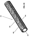
- FIGS. 18-28 illustrate various stages of the manufacture of segmented electrode assemblies.
- FIGS. 29-35 illustrate various stages of the manufacture of segmented electrode assemblies.
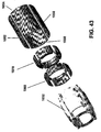
- FIGS. 36-43 illustrate various stages of the manufacture of segmented electrode assemblies.
- FIG. 3 is a flowchart illustrating a method of manufacturing a medical lead assembly.
- the medical lead assembly so manufactured may then be incorporated into the construction of a medical lead as is discussed further below.
- a tube is coupled to an electrically insulating material.
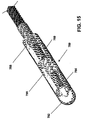
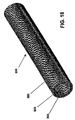
- a tube is any generally cylindrically shaped member that includes at least on its outer surface an electrically conducting material. Examples of tubes are shown in FIGS. 9 , 18 , 29 and 36 as tubes 700, 800, 900 and 1000.
- a tube may be a one piece member or it may be constructed from more than one piece. For example, tube 700 is a one piece member.
- Tubes 800, 900 and 1000 are constructed by attaching multiple components together as is described in detail below.
- a tube includes a portion that will eventually become one or more electrode segments.
- An electrode segment (also referred to as a segment) is an electrode that does not extend around the entire circumference of the lead.
- the tube also includes at least one gap and at least one bridge.
- a gap in a tube is any opening, aperture or slot in the electrically conducting portion of the tube such that the gap provides electrical isolation between adjacent electrode segments once any bridges in the tube are at least partially removed.
- a bridge is a portion of the tube that either connects adjacent electrode segments or completes the circumference of the tube in the case of only a single electrode segment.
- the tubes may be hollow. This means that there is some open space in the middle of the tubes for eventual receipt of a conductor assembly.
- At block 104 at least a portion of the bridge is removed resulting in a segmented electrode assembly having at least one segment.
- the coupled electrically insulating material holds the electrode segment or segments to the assembly so that the bridge(s) are no longer needed. Removal of the bridge or bridges or at least a portion thereof allows the segment(s) to be electrically isolated from each other.
- One embodiment of removing a bridge or portion of a bridge is to cut through the coupled tube and electrically insulating material at a location that removes the electrical connection between adjacent segments. Cutting for purposes herein includes grinding.
- FIG. 4 is a flowchart providing a more detailed example of a method of manufacturing a segmented electrode assembly.
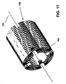
- FIGS. 9-11 show various stages of such manufacturing according to one embodiment.
- Block 200 represents making the tube.
- tube 700 of FIG. 8 is made by starting with cylindrical tubing and milling it in the longitudinal direction for each gap and two corresponding bridges desired.
- This particular example tube 700 has 4 gaps (702, 720, 722, and 724) corresponding with the fact that the segmented electrode assembly being made in this example will have 4 segments (726, 728, 730, and 732).
- tube 700 the tubing is milled in four different circumferential locations corresponding with the four gaps desired and the area around the gaps having a smaller wall thickness than the locations of the segments.
- tube start with 0.050" 90%-10% Pt/Ir tubing that has 0.006" wall thickness and mill using a 0.005" end mill.
- This particular tube 700 also includes 8 bridges (704, 706, 708, 710, 712, 714, 716 and 718) corresponding to two bridges per gap (one on each end of the tube).
- the tube may have only a single gap and one or more bridges. The bridge in this case would complete the circumference of the tube.
- the gaps 702, 720, 722 and 724 in the tube are created by laser-cutting.
- the tube is then placed in a mold at block 202 and insert molded by injecting an electrically insulating material into the mold at block 204.
- One embodiment of the resulting coupled tube and insulating material member is shown in FIG. 9 as member 734 that includes tube 700 and electrically insulating material 736.
- electrically insulating material 736 is PEEK (polyetheretherketone) or polysulfone.
- one or more or all bridges are removed or partially removed to electrically isolate the segments from each other. In one embodiment, the bridges are removed by cutting off the ends of the tube after it has been coupled with the electrically insulating material.
- end slots are machined into one or more of the segments. Machining may be performed by many different methods including, but not limited to, drilling, laser machining, EDM (electrical discharge machining), plasma cutting. These end slots are for accommodating receipt and connection of the conductors to the segments.
- FIG. 10 illustrates an almost completed segmented electrode assembly 740 having eight end slots (only five shown) 742, 744, 746, 748 and 750.
- the milled area of the tube 700 results in a retaining surface (e.g., surface 752) which results in the electrically insulating material holding the segments (e.g., segment 726) in place along their full length and preventing them from pulling or peeling away from the assembly after the bridge(s) are removed.
- a retaining surface e.g., surface 752
- the electrically insulating material holding the segments (e.g., segment 726) in place along their full length and preventing them from pulling or peeling away from the assembly after the bridge(s) are removed.
- machining end slots on both ends of a segmented electrode assembly allows the assemblies to be placed on a conductor assembly either end first.
- a hole is created in the electrically insulating material along the longitudinal axis of the member 734 at block 212.
- the hole is created by drilling.
- drilling includes boring.
- the hole 762 in the segmented electrode assembly 760 may be obtained by inserting a pin into the tube before coupling the tube with the electrically insulating material. In this way the hole 762 is reserved as the injected insulating material is not allowed to be injected into that space. After injection is completed, the pin may be removed and the end slots machined.
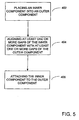
- one or more segmented electrode assemblies may be used to make a medical lead. This process is now described in conjunction with FIG. 7 .
- one or more segmented electrode assemblies are made.
- the one or more segmented electrode assemblies are placed on a conductor assembly along the longitudinal axis of the segmented electrode assembly or assemblies.
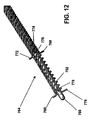
- FIG. 12 illustrates one embodiment of a conductor assembly.
- a conductor assembly is one or more conductors and supporting structure if any. The conductors may be in any configuration such as straight line or coiled. The number of conductors in the conductor assembly depends on the number of electrodes and whether or not electrodes are to be electrically coupled together.
- the lead is to have two segmented electrode assemblies each with four segments, then eight conductors are used.
- One such embodiment is shown in FIGS. 12-16 .
- Another embodiment lead 795 may have four segmented electrode assemblies 796, 797, 798 and 799 each with two segments as shown in FIG. 17 .
- This embodiment also has eight conductors.
- Another embodiment may have four segmented electrode assemblies each having four segments. In such an embodiment, sixteen conductors may be used.
- the conductors may be manufactured from a wide range of materials that are electrically conductive such as MP35N, platinum and the like.
- a conductor may comprise a plurality of wires that may be configured as braided strand wire (BSW). BSW is available in many configurations including seven wire BSW. When low impedance is desired, the core of each wire may be manufactured from a low impedance metal such as silver and the jacket may be manufactured from a material with good mechanical strength properties such as MP35N.
- One embodiment of conductor uses seven wire BSW with a silver core and an MP35N jacket typically with a resistance of less than about 0.098 ohms/cm (3 ohms/foot) and a tensile strength greater than 5N.
- the conductor may be electrically insulated with a flouro-polymer such as ethyletetraflouroethylene with a coating thickness of approximately 0.0002 cm (0.0008 inch).
- Conductor assembly 764 includes 8 conductors (768, 770, 772, 774, 776, 778, 780, 782) coiled around a stylet receiving member 766.
- Four of the conductors (768, 770, 772,774) terminate at one more proximal axial position and another four conductors (776, 778, 780, 782) terminate at a more distal axial location.
- a first segmented electrode assembly has been placed on the conductor assembly by sliding the first segmented electrode assembly onto the conductor assembly. The conductor assembly is positioned along the longitudinal axis 751 of the first segmented electrode assembly.
- the at least one of the one or more conductors of the conductor assembly are electrically coupled to at least one of the one or more segments of the one or more segmented electrode assemblies.
- One embodiment of this step is shown in FIGS. 13 and 14 .
- the ends of conductors 768, 770, 772, and 774 (shown in FIG. 12 ) are placed into the four proximal end slots (only proximal end slot 750 is shown in FIG. 13 , with the end of conductor 770 shown positioned in the end slot 750).
- a second segmented electrode assembly 784 is placed on the conductor assembly 764.
- Ends of conductors 776, 778, 780 and 782 are placed into four of the end slots in second segmented electrode assembly 784. Note that either the distal end slots 786, 788, 790 and 792 or the proximal end slots such as end slot 794 or a combination of both distal and proximal end slots may be used for receipt of the ends of conductors 776, 778, 780 and 782.
- the ends of conductors are electrically coupled to the segments of the segmented electrode assemblies. In one embodiment the conductors are welded to the end slots of the segments for such electrical coupling.
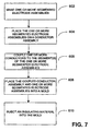
- the coupled conductor assembly and one or more segmented electrode assemblies are placed in a mold.
- adjacent segmented electrode assemblies are longitudinally spaced apart or separated by a space. This space is filled or partially filled with a second insulating material.
- a second electrically insulating material is injected into the mold at block 610 to provide the spacers 788, 790 between segmented electrode assemblies and may also include the tip 792 of the lead.
- the second electrically insulating material is injected slowly at low pressure (e.g., less than 1000 psi) to prevent displacement of electrical conductors and prevent mechanical loading of electrical connections during the injection process.
- low pressure e.g., less than 1000 psi
- the outer shape of the lead is substantially cylindrical.
- the second electrically insulating material may be the same or different from the electrically insulating material used in the making of the segmented electrode assemblies.
- the second electrically insulating material is polyurethane. This overmolding structurally connects the conductor assembly and the segmented electrode assemblies together as well as provides a smooth outer surface for the distal end of the lead by filling in the spaces between segmented electrode assemblies and the lead tip.
- FIG. 16 is a cross sectional view of lead 789.
- FIG. 5 is a flowchart showing the steps of making a tube according to the second and fourth embodiments of tubes.
- the second embodiment tube is shown in FIGS. 18-28 .
- the fourth embodiment tube is shown in FIGS. 36-43 .
- Block 402 of FIG. 5 is placing an inner component of the tube into an outer component of the tube.
- An outer component is generally cylindrical and hollow and defines one or more gaps and one or more bridges.
- One embodiment of an outer component is shown as outer component 806 in FIG. 19 .
- Outer component 806 includes four gaps such as gap 808.
- Outer component 806 also includes eight bridges (e.g., bridge 816).
- An outer component also has an inner surface which is the surface facing inward (toward the hollow space) and an outer surface facing outward.
- Outer component 806 has inner surface 812 and outer surface 814.
- the inner component is generally cylindrical and may be hollow. The inner component will also have at least one gap at a first axial position and at least one bridge at a second axial location.
- One embodiment inner component is inner component 804 in FIG. 19 .
- Inner component 804 includes four gaps including gap 810.
- Inner component 804 also includes eight bridges (e.g., bridge 818).
- An inner component also includes an outer surface that faces outward (ultimately facing the inner surface of the outer component.
- Inner component 804 has an outer surface 820.
- An inner component may also include an inner surface that faces inward (if the inner component is hollow).
- Inner component 804 includes inner surface 822.
- the outer surface of the inner component includes one or more higher portions and one or more lower portions.
- a higher portion has a greater diameter than a lower portion.
- Inner component 804 includes four higher portions 824, 826, 828, 830 and three lower portions 832, 834, and 836.
- the number of higher and lower portions may depend on how many segmented electrode assemblies are to be manufactured out of one tube.
- the particular embodiment shown in FIG. 19 is designed for manufacturing three segmented electrode assemblies from one tube by making four transverse cuts (perpendicular to the longitudinal axis of the tube) at the four higher portions.
- the inner component and outer component are aligned so that at least one of the gaps of the inner component is aligned with at least one of the gaps of the outer component.
- all four gaps of the inner component 804 are aligned with all four gaps of the outer component 806. This will result in the segmented electrode assemblies having 4 electrically isolated segments.
- the inner component is attached to the outer component resulting in a tube.
- inner component 804 is attached to outer component 806 by welding, resulting in tube 800. See for example weld locations 840, 842, 844, 846, 848 and 850.
- welding includes brazing.
- a passageway for purposes herein is defined as an encapsulated space wherein the only inlets or outlets to the encapsulated space are through one or more gaps, using the definition of the term "gap" above. See for example, passageways 801, 803, and 807 in FIG. 20 .
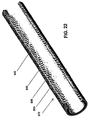
- the passageways fill or partially fill with the injected electrically insulating material as shown in FIGS. 21-24 that show one embodiment of a coupled tube and electrically insulating material 870. Electrically insulating material 805 extends into the passageways 801, 803 and 807. The existence of the electrically insulating material in the passageway or passageways provides additional retention of the segments.
- FIGS. 21-24 show one embodiment of a coupled tube and electrically insulating material 870.
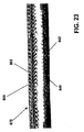
- FIG. 25-28 show various views of a segmented electrode assembly 860 after being cut from the coupled tube and electrically insulating material 870.
- the embodiment segmented electrode assembly shown in FIG. 27 includes four segments (870, 872, 874 and 876) each separated by a gap from the adjacent segments.
- the electrically insulating material 805 extends circumferentially along the inner surface 880 of the segment, in the gaps, and into the four passageways (not visible in FIG. 27 ).
- the steps of FIGS. 3 and 4 are one embodiment method for making the segmented electrode assemblies of the second, third and fourth embodiments.
- the segments e.g., 870, 872, 874 and 876) have an inner surface (e.g., inner surface 880 of segment 870) and an outer surface (e.g., outer surface 882 of segment 870).
- the inner surface of a segment is the surface facing inward toward the eventual conductor assembly and the outer surface is the surface of the segment that face the human tissue upon implantation.
- a segment may also have longitudinal edge surfaces.
- a longitudinal edge surface is a surface of a segment adjacent a gap. See for example, longitudinal edge surfaces 863, 865 and 867 in FIGS. 26 and 27 . Longitudinal edge surfaces 865 and 867 are a part of segment 870. Longitudinal edge surface 863 is part of segment 876. Insulating material 805 extends between longitudinal edge surfaces 865 and 867.
- a segmented electrode assembly of the second, third and fourth embodiments may be used to make a medical lead by the same process as described above with respect to FIGS. 7 and 12-17 .
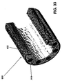
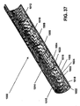
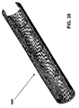
- FIGS. 36-43 show another embodiment tube and resulting segmented electrode assembly according to the steps of FIG. 5 .
- there may be one or more inner components 1002, 1004, 1006, 1008, 1010 and 1012, and an outer component 1014 that make up the tube 1000.
- Outer component includes four gaps such as gap 1016.
- Inner components include one or more gaps such as gaps 1018 and 1020.
- the inner components include a protrusion extending inward toward the inside of the inner component and configured to anchor the segments in the electrically insulating material.
- the protrusion may include a first portion that is generally perpendicular to the inner surface of the inner component and a second portion that is generally perpendicular to the first portion.
- This second portion is an undercut surface and it provides the anchoring of the segment in the electrically insulating material.
- the protrusion is a hook shaped protrusion such as hook 1015.
- the first portion that is generally perpendicular to the inner surface 1022 is identified as portion 1024, and the second portion that is generally perpendicular to the first portion 1024 is identified as second portion 1026 (see FIG. 37 ).
- the first portion and second portion may be curved as long as they have at least a component of their direction be in the described directions.
- second portion 1026 is curved but has a component of its position in a direction perpendicular to the first portion 1024.
- the inner components may include one or more bridges that are removed or partially removed after the electrically insulating material is coupled to the tube.
- One embodiment method of partially or wholly removing the bridges is by cutting through the coupled tube and electrically insulating material in a direction generally perpendicular to the longitudinal axis of the tube. Example cut locations are shown as 1003, 1005, 1007, 1009, 1011 and 1013 in FIG. 36 . These cuts would result in three segmented electrode assemblies. Specifically the three assemblies would be those portions between cuts 1003 and 1005, between 1007 and 1009, and between 1011 and 1013.
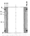
- FIG. 38 is another view of the tube 1000 before being coupled with an electrically insulating material.
- FIGS. 39 and 40 show various views of a coupled tube and electrically insulating material 1030 according to this embodiment before partial or whole removal of the bridges. Electrically insulating material 1032 surrounds the hooks such as hook 1015.
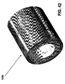
- FIGS. 41 and 42 show different views of a segmented electrode assembly 1050 after being cut out of the coupled tube and electrically insulating material 1030. Assembly 1050 includes segments1052, 1054, 1056 and 1058. These segments are now electrically insulated from each other by electrically insulating material 1032.
- FIG. 43 is an exploded view of the assembly 1050. 1060 and 1070 are the portions of segments 1052, 1054, 1056 and 1058 that originally came from the inner component of the tube.
- FIG. 6 is a flowchart showing an alternative step to making a tube.
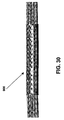
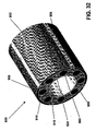
- FIGS. 29-35 show an alternative embodiment tube and resulting segmented electrode assemblies made according to the flowchart of FIG. 6 .
- one or more rods are attached to an inner surface of an outer component. There may be one rod per segment or multiple rods per segment. In the embodiment of FIGS. 29-35 , there are two rods per segment.
- the outer component is defined the same as discussed above with earlier embodiments. "Rod" means any member extending substantially along the full length or greater of the outer component when situated parallel to the longitudinal axis of the outer component.
- Rods may be of any shape such that once attached to a segment and coupled with electrically insulating material, there is electrically insulating material between any point on the rod and any point on the segment along a line passing through such point on the segment and perpendicular to a tangent to the segment.
- the rods are attached to the outer component.
- the rods are attached to the outer component 918 by welding. See for example, weld locations 922 and 923.
- outer component 918 has gaps such as gap 920, and bridges such as bridge 926.
- the rods have been welded to the outer component and to form a tube.
- the tube has been coupled to polyurethane by placing the tube into a mold and injecting the polyurethane into the mold.
- the resulting coupled tube and electrically insulating material 900 is shown.
- FIGS. 31-35 show various views of a segmented electrode assembly 950 that has been cut from the coupled tube and insulating material 900.
- the assembly 950 includes segments 952, 954, 956 and 958.
- the various segmented electrodes may be activated to deliver electric pulses or deactivated independently of each other.
- segments may be electrically coupled together. For example, in a DBS application with 4 quarter segments, the two opposite segments could be electrically coupled together. Electrically coupling segments together may be accomplished by welding the same conductor to both segments or by leaving a bridge between the two segments.
Landscapes
- Health & Medical Sciences (AREA)
- Life Sciences & Earth Sciences (AREA)
- Engineering & Computer Science (AREA)
- General Health & Medical Sciences (AREA)
- Animal Behavior & Ethology (AREA)
- Heart & Thoracic Surgery (AREA)
- Veterinary Medicine (AREA)
- Biomedical Technology (AREA)
- Public Health (AREA)
- Cardiology (AREA)
- Radiology & Medical Imaging (AREA)
- Physiology (AREA)
- Neurology (AREA)
- Nuclear Medicine, Radiotherapy & Molecular Imaging (AREA)
- Orthopedic Medicine & Surgery (AREA)
- Manufacturing & Machinery (AREA)
- Mechanical Engineering (AREA)
- Neurosurgery (AREA)
- Physics & Mathematics (AREA)
- Biophysics (AREA)
- Pathology (AREA)
- Medical Informatics (AREA)
- Molecular Biology (AREA)
- Surgery (AREA)
- Electrotherapy Devices (AREA)
- Ultra Sonic Daignosis Equipment (AREA)
Claims (15)
- Fil médical comportant :un ensemble de conducteurs comportant au moins un premier conducteur ;un premier ensemble d'électrodes définissant un trou, dans lequel l'ensemble de conducteurs passe à travers le trou, et dans lequel le premier ensemble d'électrodes comporte :au moins un premier segment conducteur qui est une électrode électriquement couplée au premier conducteur, le premier segment conducteur comportant une première surface intérieure, dirigée vers l'intérieur en direction de l'ensemble de conducteurs, et une première surface extérieure, dirigée vers le tissu humain, en utilisation, et définissant un premier passage entre la première surface intérieure et la première surface extérieure ; etun matériau isolant qui s'étend à travers le premier passage, et dans lequel le matériau isolant s'étend dans au moins un premier interstice adjacent au premier segment conducteur, caractérisé en ce que l'électrode est segmentée, de telle sorte qu'elle ne s'étend pas autour de la circonférence complète du corps de fil.
- Fil médical selon la revendication 1, dans lequel le premier segment conducteur comporte un premier bord longitudinal et un deuxième bord longitudinal, dans lequel l'ensemble de conducteurs comporte en outre un second conducteur, et dans lequel le premier ensemble d'électrodes segmentées comporte également :un second segment conducteur électriquement couplé au second conducteur, dans lequel le second segment conducteur comporte une seconde surface intérieure, une deuxième surface extérieure, un troisième bord longitudinal et un quatrième bord longitudinal, et dans lequel le second segment définit un second passage entre la deuxième surface intérieure et la deuxième surface extérieure, dans lequel le premier interstice se situe entre le premier bord longitudinal du premier segment conducteur et le troisième bord longitudinal du second segment conducteur ;un second interstice entre le deuxième bord longitudinal du premier segment conducteur et le quatrième bord longitudinal du second segment conducteur, dans lequel le matériau isolant s'étend également à travers le second passage et s'étend dans le second interstice.
- Fil médical selon la revendication 1, dans lequel le premier segment conducteur comporte un composant intérieur soudé à un composant extérieur, dans lequel le composant intérieur comporte la première surface intérieure du segment conducteur, et une troisième surface extérieure, et dans lequel le composant extérieur comporte la première surface extérieure du segment conducteur et une troisième surface intérieure, dans lequel la troisième surface intérieure est dirigée vers la troisième surface extérieure.
- Fil médical selon la revendication 3, dans lequel la troisième surface extérieure comporte une première partie supérieure ayant un premier diamètre, et une première partie inférieure ayant un second diamètre, dans lequel le premier diamètre est plus grand que le second diamètre.
- Fil médical selon la revendication 1, dans lequel le matériau électriquement isolant s'étend de manière circonférentielle le long de la surface intérieure du premier segment conducteur.
- Fil médical selon la revendication 1, dans lequel l'ensemble de conducteurs comporte également un second conducteur, et dans lequel le fil médical comporte en outre un deuxième ensemble d'électrodes segmentées définissant un second trou dans lequel l'ensemble de conducteurs passe à travers le second trou, et dans lequel le deuxième ensemble d'électrodes segmentées comporte :au moins un second segment conducteur électriquement couplé au second conducteur, le second segment conducteur comportant une deuxième surface intérieure et une deuxième surface extérieure et définissant un second passage entre la deuxième surface intérieure et la deuxième surface extérieure ; etun deuxième matériau isolant qui s'étend à travers le second passage, et dans lequel le deuxième matériau isolant s'étend dans au moins un second interstice adjacent au second segment conducteur.
- Fil médical selon la revendication 6, dans lequel le premier ensemble d'électrodes segmentées est longitudinalement espacé par rapport au deuxième ensemble d'électrodes segmentées par un premier espace, et dans lequel le premier espace est au moins partiellement rempli à l'aide d'un troisième matériau isolant, dans lequel les premier et deuxième ensembles d'électrodes segmentées et le troisième matériau isolant forment une forme extérieure sensiblement cylindrique.
- Fil médical selon la revendication 7, comportant en outre des troisième et quatrième ensembles d'électrodes segmentées, et dans lequel le troisième ensemble d'électrodes segmentées est espacé par rapport au deuxième ensemble d'électrodes segmentées par un deuxième espace, et dans lequel le quatrième ensemble d'électrodes segmentées est espacé par rapport au troisième ensemble d'électrodes segmentées par un troisième espace, et dans lequel les deuxième et troisième espaces sont au moins partiellement remplis à l'aide du troisième matériau isolant, dans lequel la forme extérieure sensiblement cylindrique inclut les troisième et quatrième ensembles d'électrodes segmentées et le troisième matériau isolant dans les deuxième et troisième espaces.
- Fil médical selon la revendication 8, dans lequel les premier, deuxième, troisième et quatrième ensembles d'électrodes segmentées comportent également chacun des deuxième, troisième et quatrième segments conducteurs chacun électriquement couplés à un conducteur de l'ensemble de conducteurs.
- Fil médical selon la revendication 6, dans lequel le premier matériau isolant est le même type de matériau que le premier matériau isolant.
- Fil médical selon la revendication 10, dans lequel les premier et deuxième matériaux isolants comportent de la polysulfone.
- Fil médical selon la revendication 10, dans lequel les premier et deuxième matériaux isolants comportent de la PEEK.
- Fil médical selon la revendication 7, dans lequel le troisième matériau isolant comporte du polyuréthane.
- Fil médical selon la revendication 1, dans lequel le premier conducteur de l'ensemble de conducteurs est en spirale.
- Fil médical selon la revendication 1, dans lequel le premier segment conducteur est configuré pour définir une fente d'extrémité, et dans lequel le premier conducteur est soudé au premier segment conducteur dans la fente d'extrémité.
Applications Claiming Priority (2)
| Application Number | Priority Date | Filing Date | Title |
|---|---|---|---|
| US64863505P | 2005-01-31 | 2005-01-31 | |
| PCT/US2006/003426 WO2006083884A1 (fr) | 2005-01-31 | 2006-01-31 | Derivation medicale munie d’une electrode segmentee |
Publications (2)
| Publication Number | Publication Date |
|---|---|
| EP1846092A1 EP1846092A1 (fr) | 2007-10-24 |
| EP1846092B1 true EP1846092B1 (fr) | 2012-07-04 |
Family
ID=36406118
Family Applications (2)
| Application Number | Title | Priority Date | Filing Date |
|---|---|---|---|
| EP06719991A Not-in-force EP1848496B1 (fr) | 2005-01-31 | 2006-01-31 | Methode de fabrication d'un cable medical |
| EP06734129A Active EP1846092B1 (fr) | 2005-01-31 | 2006-01-31 | Derivation medical munie d'une electrode segmentee |
Family Applications Before (1)
| Application Number | Title | Priority Date | Filing Date |
|---|---|---|---|
| EP06719991A Not-in-force EP1848496B1 (fr) | 2005-01-31 | 2006-01-31 | Methode de fabrication d'un cable medical |
Country Status (5)
| Country | Link |
|---|---|
| US (3) | US8000808B2 (fr) |
| EP (2) | EP1848496B1 (fr) |
| AT (1) | ATE448830T1 (fr) |
| DE (1) | DE602006010515D1 (fr) |
| WO (2) | WO2006083884A1 (fr) |
Families Citing this family (153)
| Publication number | Priority date | Publication date | Assignee | Title |
|---|---|---|---|---|
| US7035690B2 (en) | 2002-11-15 | 2006-04-25 | Medtronic, Inc. | Human-implantable-neurostimulator user interface having multiple levels of abstraction |
| US9079018B2 (en) | 2004-10-21 | 2015-07-14 | Medtronic, Inc. | Implantable medical electrical leads, kits, systems and methods of use thereof |
| US8380321B2 (en) | 2006-02-24 | 2013-02-19 | Medtronic, Inc. | Programming interface with a cross-sectional view of a stimulation lead with complex electrode array geometry |
| US8612024B2 (en) | 2006-02-24 | 2013-12-17 | Medtronic, Inc. | User interface with 3D environment for configuring stimulation therapy |
| US9642982B2 (en) * | 2006-05-05 | 2017-05-09 | Cathrx Ltd. | Modular catheter assembly |
| US8321025B2 (en) | 2006-07-31 | 2012-11-27 | Cranial Medical Systems, Inc. | Lead and methods for brain monitoring and modulation |
| US7583999B2 (en) | 2006-07-31 | 2009-09-01 | Cranial Medical Systems, Inc. | Multi-channel connector for brain stimulation system |
| WO2008014557A1 (fr) * | 2006-08-04 | 2008-02-07 | Cathrx Ltd | Ensemble de poignée de catheter |
| US20080114230A1 (en) * | 2006-11-14 | 2008-05-15 | Bruce Addis | Electrode support |
| US9399130B2 (en) | 2007-04-25 | 2016-07-26 | Medtronic, Inc. | Cannula configured to deliver test stimulation |
| US9561053B2 (en) | 2007-04-25 | 2017-02-07 | Medtronic, Inc. | Implant tool to facilitate medical device implantation |
| US7668601B2 (en) * | 2007-04-26 | 2010-02-23 | Medtronic, Inc. | Implantable medical lead with multiple electrode configurations |
| US8359100B2 (en) * | 2007-06-20 | 2013-01-22 | Advanced Neuromodulation Systems, Inc. | Method for selecting electrodes for deep brain or cortical stimulation and pulse generator for deep brain or cortical stimulation |
| WO2009025817A2 (fr) | 2007-08-20 | 2009-02-26 | Medtronic, Inc. | Evaluation de configurations d'électrode de stimulation thérapeutique sur la base de réponses physiologiques |
| EP2195081A1 (fr) * | 2007-08-20 | 2010-06-16 | Medtronic, INC. | Configurations d'électrode pour des conducteurs directionnels |
| WO2009025824A1 (fr) | 2007-08-20 | 2009-02-26 | Medtronic, Inc. | Conducteur médical implantable avec électrode polarisée |
| JP5400784B2 (ja) * | 2007-10-09 | 2014-01-29 | ボストン サイエンティフィック リミテッド | 電気生理学電極および電気生理学電極を含む装置 |
| US8515555B1 (en) * | 2007-10-09 | 2013-08-20 | Advanced Neuromodulation Systems, Inc. | Extension device for coupling between pulse generator and stimulation lead, stimulation system using the same, and method of manufacturing the same |
| WO2009048943A1 (fr) | 2007-10-09 | 2009-04-16 | Boston Scientific Scimed, Inc. | Dispositifs à cathéter d'ablation refroidi et procédés d'utilisation |
| US8364284B2 (en) | 2008-09-15 | 2013-01-29 | Boston Scientific Neuromodulation Corporation | Implantable electric stimulation system and methods of making and using |
| US20130303017A9 (en) * | 2008-05-28 | 2013-11-14 | Robert G. Walsh | Adapter for electrode and connector attachments for a cylindrical glass fiber fine wire lead |
| US9513443B2 (en) | 2008-05-28 | 2016-12-06 | John Lawrence Erb | Optical fiber-fine wire conductor and connectors |
| US9242100B2 (en) | 2012-08-07 | 2016-01-26 | Nuax, Inc. | Optical fiber-fine wire lead for electrostimulation and sensing |
| US9025598B1 (en) | 2012-03-22 | 2015-05-05 | Nuax, Inc. | Cable/guidewire/interconnects communication apparatus and methods |
| US20110220408A1 (en) * | 2009-02-23 | 2011-09-15 | Walsh Robert G | Electrode and connector attachments for a cylindrical glass fiber wire lead |
| US9193313B2 (en) | 2012-03-22 | 2015-11-24 | Nuax, Inc. | Methods and apparatuses involving flexible cable/guidewire/interconnects |
| US8692117B2 (en) | 2008-05-28 | 2014-04-08 | Cardia Access, Inc. | Durable fine wire electrical conductor suitable for extreme environment applications |
| WO2009148939A1 (fr) | 2008-06-03 | 2009-12-10 | Medtronic, Inc. | Fil présentant des contacts radialement espacés pour faciliter la réglabilité |
| EP3536376A1 (fr) | 2008-07-30 | 2019-09-11 | Ecole Polytechnique Fédérale de Lausanne | Appareil de stimulation optimisée d'une cible neurologique |
| US8307717B2 (en) * | 2008-08-22 | 2012-11-13 | Refractory Anchors, Inc. | Method and apparatus for installing an insulation material to a surface and testing thereof |
| US20100076535A1 (en) | 2008-09-25 | 2010-03-25 | Boston Scientific Neuromodulation Corporation | Leads with non-circular-shaped distal ends for brain stimulation systems and methods of making and using |
| US8359107B2 (en) | 2008-10-09 | 2013-01-22 | Boston Scientific Neuromodulation Corporation | Electrode design for leads of implantable electric stimulation systems and methods of making and using |
| US8255057B2 (en) | 2009-01-29 | 2012-08-28 | Nevro Corporation | Systems and methods for producing asynchronous neural responses to treat pain and/or other patient conditions |
| US9403020B2 (en) | 2008-11-04 | 2016-08-02 | Nevro Corporation | Modeling positions of implanted devices in a patient |
| CA2743575C (fr) | 2008-11-12 | 2017-01-31 | Ecole Polytechnique Federale De Lausanne | Dispositif de neurostimulation microfabrique |
| US8644919B2 (en) | 2008-11-13 | 2014-02-04 | Proteus Digital Health, Inc. | Shielded stimulation and sensing system and method |
| JP2012508624A (ja) | 2008-11-13 | 2012-04-12 | プロテウス バイオメディカル インコーポレイテッド | 多重化複数電極神経刺激装置 |
| WO2010121170A1 (fr) | 2009-04-16 | 2010-10-21 | Boston Scientific Neuromodulation Corporation | Orientation d'un courant de stimulation cérébrale profonde au moyen d'électrodes séparées |
| EP2243510B1 (fr) | 2009-04-22 | 2014-04-09 | Nevro Corporation | Systèmes pour la modulation haute fréquence sélective de la moelle épinière pour inhiber la douleur avec des effets secondaires réduits |
| AU2010238752B2 (en) | 2009-04-22 | 2014-05-29 | Nevro Corporation | Spinal cord modulation for inducing paresthetic and anesthetic effects, and associated systems and methods |
| US8250755B2 (en) * | 2009-04-24 | 2012-08-28 | Advanced Neuromodulation Systems, Inc. | Process for fabricating a medical lead |
| US8225504B2 (en) * | 2009-04-24 | 2012-07-24 | Advanced Neuromodulation Systems, Inc. | Medical leads with segmented electrodes and methods of fabrication thereof |
| US8046909B2 (en) * | 2009-04-24 | 2011-11-01 | Advanced Neuromodulation Systems, Inc. | Method of fabricating stimulation lead |
| US20100318019A1 (en) * | 2009-06-15 | 2010-12-16 | Pacesetter, Inc. | Electrophysiology devices employing electrically conductive polymer conductors and methods of manufacturing such devices |
| US8887387B2 (en) * | 2009-07-07 | 2014-11-18 | Boston Scientific Neuromodulation Corporation | Methods of manufacture of leads with a radially segmented electrode array |
| AU2015203701B2 (en) * | 2009-07-07 | 2016-10-20 | Boston Scientific Neuromodulation Corporation | Systems and leads with a radially segmented electrode array and methods of manufacture |
| US8875391B2 (en) | 2009-07-07 | 2014-11-04 | Boston Scientific Neuromodulation Corporation | Methods for making leads with radially-aligned segmented electrodes for electrical stimulation systems |
| US8498710B2 (en) | 2009-07-28 | 2013-07-30 | Nevro Corporation | Linked area parameter adjustment for spinal cord stimulation and associated systems and methods |
| US20110047795A1 (en) * | 2009-09-01 | 2011-03-03 | Kevin Turner | Medical leads with segmented electrodes and methods of fabrication thereof |
| US20110077699A1 (en) * | 2009-09-30 | 2011-03-31 | John Swanson | Medical leads with segmented electrodes and methods of fabrication thereof |
| US8171621B2 (en) * | 2009-09-30 | 2012-05-08 | Advanced Neuromodulation Systems, Inc. | Methods of fabrication of a simulation lead |
| US9054436B2 (en) * | 2009-09-30 | 2015-06-09 | Advanced Neuromodulation Systems, Inc. | Method of fabricating stimulation lead for applying electrical stimulation to tissue of a patient |
| US11045221B2 (en) * | 2009-10-30 | 2021-06-29 | Medtronic, Inc. | Steerable percutaneous paddle stimulation lead |
| US8391985B2 (en) * | 2009-11-30 | 2013-03-05 | Boston Scientific Neuromodulation Corporation | Electrode array having concentric windowed cylinder electrodes and methods of making the same |
| US8788063B2 (en) | 2009-11-30 | 2014-07-22 | Boston Scientific Neuromodulation Corporation | Electrode array having a rail system and methods of manufacturing the same |
| US8295944B2 (en) | 2009-11-30 | 2012-10-23 | Boston Scientific Neuromodulation Corporation | Electrode array with electrodes having cutout portions and methods of making the same |
| US8874232B2 (en) | 2009-11-30 | 2014-10-28 | Boston Scientific Neuromodulation Corporation | Electrode array having concentric split ring electrodes and methods of making the same |
| CA2782710C (fr) | 2009-12-01 | 2019-01-22 | Ecole Polytechnique Federale De Lausanne | Dispositif de neurostimulation microfabrique et ses procedes de fabrication et d'utilisation |
| US8571665B2 (en) * | 2010-03-23 | 2013-10-29 | Boston Scientific Neuromodulation Corporation | Helical radial spacing of contacts on a cylindrical lead |
| SG184395A1 (en) | 2010-04-01 | 2012-11-29 | Ecole Polytech | Device for interacting with neurological tissue and methods of making and using the same |
| JP5834065B2 (ja) * | 2010-04-02 | 2015-12-16 | ボストン サイエンティフィック ニューロモデュレイション コーポレイション | 指向性リード線アセンブリ |
| US8868206B2 (en) | 2010-06-18 | 2014-10-21 | Boston Scientific Neuromodulation Corporation | Electrode array having embedded electrodes and methods of making the same |
| WO2012009181A2 (fr) | 2010-07-16 | 2012-01-19 | Boston Scientific Neuromodulation Corporation | Systèmes et procédés pour la direction radiale de groupements d'électrodes |
| US8583237B2 (en) | 2010-09-13 | 2013-11-12 | Cranial Medical Systems, Inc. | Devices and methods for tissue modulation and monitoring |
| US8694127B2 (en) | 2010-09-21 | 2014-04-08 | Boston Scientific Neuromodulation Corporation | Systems and methods for making and using radially-aligned segmented electrodes for leads of electrical stimulation systems |
| US8965482B2 (en) | 2010-09-30 | 2015-02-24 | Nevro Corporation | Systems and methods for positioning implanted devices in a patient |
| US8805519B2 (en) | 2010-09-30 | 2014-08-12 | Nevro Corporation | Systems and methods for detecting intrathecal penetration |
| WO2012075198A2 (fr) | 2010-11-30 | 2012-06-07 | Nevro Corporation | Analgésie prolongée par le biais d'une modulation haute fréquence de la moelle épinière, et systèmes et procédés associés |
| EP2654876B1 (fr) | 2010-12-23 | 2014-12-10 | Boston Scientific Neuromodulation Corporation | Procédé et un ensemble pour fabriquer un conducteur médical comprenant l'enlèvement par abrasion de connecteurs en saillie |
| US8700179B2 (en) * | 2011-02-02 | 2014-04-15 | Boston Scientific Neuromodulation Corporation | Leads with spiral of helical segmented electrode arrays and methods of making and using the leads |
| US20120203316A1 (en) | 2011-02-08 | 2012-08-09 | Boston Scientific Neuromodulation Corporation | Leads with segmented electrodes for electrical stimulation of planar regions and methods of making and using |
| ES2548833T3 (es) | 2011-02-08 | 2015-10-21 | Boston Scientific Neuromodulation Corporation | Cables con electrodos segmentados para sistemas de estimulación eléctrica |
| ES2717196T3 (es) | 2011-02-08 | 2019-06-19 | Boston Scient Neuromodulation Corp | Cables conductores con electrodos segmentados que tienen un canal y procedimientos de fabricación de los cables conductores |
| WO2013036880A1 (fr) | 2011-09-08 | 2013-03-14 | Thacker James R | Modulation sélective à haute fréquence de la moelle épinière pour atténuer la douleur, y compris les douleur céphaliques et / ou du corps entier, avec effets secondaires réduits, et systèmes et procédés associés |
| ES2829585T3 (es) | 2012-01-25 | 2021-06-01 | Nevro Corp | Anclajes de cables y sistemas y métodos asociados |
| US8831742B2 (en) | 2012-01-26 | 2014-09-09 | Boston Scientific Neuromodulation Corporation | Systems and methods for identifying the circumferential positioning of electrodes of leads for electrical stimulation systems |
| WO2013148092A1 (fr) | 2012-03-30 | 2013-10-03 | Boston Scientific Neuromodulation Corporation | Dérivations à capsules fluorescentes de rayons x pour identification d'électrode et procédés de fabrication ainsi que leur utilisation |
| WO2013147984A1 (fr) | 2012-03-30 | 2013-10-03 | Medtronic, Inc. | Adaptateur à pattes pour systèmes médicaux permettant de générer un modèle de stimulation personnalisé pour une patte secondaire |
| EP2841149B1 (fr) * | 2012-04-27 | 2020-07-08 | Medtronic, Inc. | Procédé et un système pour la fabrication d'un conducteur médical moyennant un porte-électrodes |
| JP5926453B2 (ja) | 2012-06-01 | 2016-05-25 | ボストン サイエンティフィック ニューロモデュレイション コーポレイション | 電気刺激システムのためのチップ電極を有するリード及びそれを製造し使用する方法 |
| US9833614B1 (en) | 2012-06-22 | 2017-12-05 | Nevro Corp. | Autonomic nervous system control via high frequency spinal cord modulation, and associated systems and methods |
| US8897891B2 (en) | 2012-08-03 | 2014-11-25 | Boston Scientific Neuromodulation Corporation | Leads with electrode carrier for segmented electrodes and methods of making and using |
| US9308022B2 (en) | 2012-12-10 | 2016-04-12 | Nevro Corporation | Lead insertion devices and associated systems and methods |
| US9440076B2 (en) | 2013-03-15 | 2016-09-13 | Globus Medical, Inc. | Spinal cord stimulator system |
| US9878170B2 (en) | 2013-03-15 | 2018-01-30 | Globus Medical, Inc. | Spinal cord stimulator system |
| US10493265B2 (en) | 2013-03-15 | 2019-12-03 | Medtronic, Inc. | Medical leads and techniques for manufacturing the same |
| US9887574B2 (en) | 2013-03-15 | 2018-02-06 | Globus Medical, Inc. | Spinal cord stimulator system |
| US9872997B2 (en) | 2013-03-15 | 2018-01-23 | Globus Medical, Inc. | Spinal cord stimulator system |
| US10406349B2 (en) | 2013-03-15 | 2019-09-10 | Medtronic, Inc. | Medical leads and techniques for manufacturing the same |
| AU2014265854A1 (en) | 2013-05-15 | 2015-11-12 | Boston Scientific Neuromodulation Corporation | Systems and methods for making tip electrodes for leads of electrical stimulation systems |
| WO2014193760A1 (fr) | 2013-05-31 | 2014-12-04 | Boston Scientific Neuromodulation Corporation | Conducteurs pourvus d'électrodes segmentées et procédés de fabrication desdits conducteurs |
| WO2014193758A1 (fr) | 2013-05-31 | 2014-12-04 | Boston Scientific Neuromodulation Corporation | Fils d'électrode segmentés formés à partir de pré-électrodes munies des dépressions ou d'ouvertures et procédé de fabrication |
| CA2911239A1 (fr) | 2013-05-31 | 2014-12-04 | Boston Scientific Neuromodulation Corporation | Conducteurs contenant des electrodes segmentees pourvues de pattes non perpendiculaires et procedes de fabrication et d'utilisation desdits conducteurs |
| WO2014193759A1 (fr) * | 2013-05-31 | 2014-12-04 | Boston Scientific Neuromodulation Corporation | Conducteurs d'électrodes segmentées formés de pré-électrodes avec des éléments d'alignement et procédés de fabrication et d'utilisation des conducteurs |
| US9895539B1 (en) | 2013-06-10 | 2018-02-20 | Nevro Corp. | Methods and systems for disease treatment using electrical stimulation |
| US9265935B2 (en) | 2013-06-28 | 2016-02-23 | Nevro Corporation | Neurological stimulation lead anchors and associated systems and methods |
| JP6072986B2 (ja) | 2013-07-12 | 2017-02-01 | ボストン サイエンティフィック ニューロモデュレイション コーポレイション | セグメント電極を備えたリード並びにリードの製造及び使用方法 |
| AU2014293477A1 (en) | 2013-07-22 | 2016-01-28 | Boston Scientific Neuromodulation Corporation | Methods of manufacturing molded segmented electrode leads |
| US9089689B2 (en) | 2013-08-30 | 2015-07-28 | Boston Scientific Neuromodulation Corporation | Methods of making segmented electrode leads using flanged carrier |
| US10149978B1 (en) | 2013-11-07 | 2018-12-11 | Nevro Corp. | Spinal cord modulation for inhibiting pain via short pulse width waveforms, and associated systems and methods |
| EP3077039B1 (fr) | 2013-12-02 | 2021-10-13 | Boston Scientific Neuromodulation Corporation | Procédés pour le fabrication des sondes pour la stimulation électrique avec électrodes arrangées en hélice |
| US9370653B2 (en) | 2013-12-05 | 2016-06-21 | Advanced Neuromodulation Systems, Inc. | Medical leads with segmented electrodes and methods of fabrication thereof |
| US20150202432A1 (en) * | 2014-01-22 | 2015-07-23 | Pacesetter, Inc. | Electrode structure for deep brain stimulation |
| EP3142745B1 (fr) | 2014-05-16 | 2018-12-26 | Aleva Neurotherapeutics SA | Dispositif pour l'interaction avec un tissu neurologique |
| US11311718B2 (en) | 2014-05-16 | 2022-04-26 | Aleva Neurotherapeutics Sa | Device for interacting with neurological tissue and methods of making and using the same |
| JP2017517374A (ja) | 2014-06-13 | 2017-06-29 | ボストン サイエンティフィック ニューロモデュレイション コーポレイション | セグメント電極のための電極担体を有するリード及びそれを製造する方法及び使用する方法 |
| US9403011B2 (en) | 2014-08-27 | 2016-08-02 | Aleva Neurotherapeutics | Leadless neurostimulator |
| US9474894B2 (en) | 2014-08-27 | 2016-10-25 | Aleva Neurotherapeutics | Deep brain stimulation lead |
| US9925376B2 (en) | 2014-08-27 | 2018-03-27 | Aleva Neurotherapeutics | Treatment of autoimmune diseases with deep brain stimulation |
| US9770598B2 (en) | 2014-08-29 | 2017-09-26 | Boston Scientific Neuromodulation Corporation | Systems and methods for making and using improved connector contacts for electrical stimulation systems |
| US9604068B2 (en) | 2014-11-10 | 2017-03-28 | Boston Scientific Neuromodulation Corporation | Systems and methods for making and using improved connector contacts for electrical stimulation systems |
| US9561362B2 (en) | 2014-11-10 | 2017-02-07 | Boston Scientific Neuromodulation Corporation | Systems and methods for making and using improved contact arrays for electrical stimulation systems |
| EP3229891B1 (fr) | 2015-02-06 | 2019-08-14 | Boston Scientific Neuromodulation Corporation | Systèmes avec réseaux de contact améliorés pour systèmes de stimulation électrique |
| WO2016164361A1 (fr) | 2015-04-10 | 2016-10-13 | Boston Scientific Neuromodulation Corporation | Systèmes et procédés de fabrication et d'utilisation de réseaux de contact améliorés pour des systèmes de stimulation électrique |
| US9364659B1 (en) | 2015-04-27 | 2016-06-14 | Dantam K. Rao | Smart lead for deep brain stimulation |
| US11051889B2 (en) | 2015-05-10 | 2021-07-06 | Alpha Omega Engineering Ltd. | Brain navigation methods and device |
| WO2016182997A2 (fr) | 2015-05-10 | 2016-11-17 | Alpha Omega Neuro Technologies, Ltd. | Système de guidage automatique de sonde cérébrale |
| US11234632B2 (en) | 2015-05-10 | 2022-02-01 | Alpha Omega Engineering Ltd. | Brain navigation lead |
| US9656093B2 (en) | 2015-07-16 | 2017-05-23 | Boston Scientific Neuromodulation Corporation | Systems and methods for making and using connector contact arrays for electrical stimulation systems |
| US9956394B2 (en) | 2015-09-10 | 2018-05-01 | Boston Scientific Neuromodulation Corporation | Connectors for electrical stimulation systems and methods of making and using |
| US10413737B2 (en) | 2015-09-25 | 2019-09-17 | Boston Scientific Neuromodulation Corporation | Systems and methods for providing therapy using electrical stimulation to disrupt neuronal activity |
| US11318310B1 (en) | 2015-10-26 | 2022-05-03 | Nevro Corp. | Neuromodulation for altering autonomic functions, and associated systems and methods |
| US10328271B2 (en) | 2015-11-12 | 2019-06-25 | Medtronic, Inc. | Implantable electrical stimulator with deflecting tip lead |
| US10342983B2 (en) | 2016-01-14 | 2019-07-09 | Boston Scientific Neuromodulation Corporation | Systems and methods for making and using connector contact arrays for electrical stimulation systems |
| US20170209699A1 (en) | 2016-01-25 | 2017-07-27 | Nevro Corp. | Treatment of congestive heart failure with electrical stimulation, and associated systems and methods |
| US10201713B2 (en) | 2016-06-20 | 2019-02-12 | Boston Scientific Neuromodulation Corporation | Threaded connector assembly and methods of making and using the same |
| US10307602B2 (en) | 2016-07-08 | 2019-06-04 | Boston Scientific Neuromodulation Corporation | Threaded connector assembly and methods of making and using the same |
| US10912475B2 (en) * | 2016-08-24 | 2021-02-09 | Biosense Webster (Israel) Ltd | Catheter with split electrode sleeve and related methods |
| US10543374B2 (en) | 2016-09-30 | 2020-01-28 | Boston Scientific Neuromodulation Corporation | Connector assemblies with bending limiters for electrical stimulation systems and methods of making and using same |
| WO2018089168A1 (fr) * | 2016-11-11 | 2018-05-17 | Medtronic, Inc. | Structure d'électrode pour dérivations médicales implantables |
| US10576269B2 (en) | 2017-01-03 | 2020-03-03 | Boston Scientific Neuromodulation Corporation | Force-decoupled and strain relieving lead and methods of making and using |
| US10905871B2 (en) | 2017-01-27 | 2021-02-02 | Boston Scientific Neuromodulation Corporation | Lead assemblies with arrangements to confirm alignment between terminals and contacts |
| WO2018160495A1 (fr) | 2017-02-28 | 2018-09-07 | Boston Scientific Neuromodulation Corporation | Connecteur sans outil permettant de verrouiller des fils de stimulation et procédés de fabrication et d'utilisation |
| WO2018165391A1 (fr) | 2017-03-09 | 2018-09-13 | Nevro Corp. | Dérivations à palette et outils de mise en place, et systèmes et procédés associés |
| US10603499B2 (en) | 2017-04-07 | 2020-03-31 | Boston Scientific Neuromodulation Corporation | Tapered implantable lead and connector interface and methods of making and using |
| WO2019023067A1 (fr) | 2017-07-25 | 2019-01-31 | Boston Scientific Neuromodulation Corporation | Systèmes et procédés de fabrication et d'utilisation d'un connecteur amélioré pour système de stimulation électrique |
| US10953221B2 (en) * | 2017-08-30 | 2021-03-23 | Medtronic, Inc. | Medical lead with segmented electrodes |
| EP3681588B1 (fr) | 2017-09-15 | 2023-05-10 | Boston Scientific Neuromodulation Corporation | Connecteur de fil sollicité pour ensemble câble de salle d'opération |
| EP3681587B1 (fr) | 2017-09-15 | 2023-08-23 | Boston Scientific Neuromodulation Corporation | Connecteur de fil actionnable pour ensemble câble de salle d'opération |
| EP3459593B1 (fr) * | 2017-09-20 | 2020-10-21 | Sorin CRM SAS | Ensemble implantable comprennant un capuchon de connecteur électrique pour un fil implantable ainsi que ledit fil |
| US11139603B2 (en) | 2017-10-03 | 2021-10-05 | Boston Scientific Neuromodulation Corporation | Connectors with spring contacts for electrical stimulation systems and methods of making and using same |
| US11103712B2 (en) | 2018-01-16 | 2021-08-31 | Boston Scientific Neuromodulation Corporation | Connector assemblies with novel spacers for electrical stimulation systems and methods of making and using same |
| US10702692B2 (en) | 2018-03-02 | 2020-07-07 | Aleva Neurotherapeutics | Neurostimulation device |
| EP3758793A4 (fr) | 2018-03-29 | 2021-12-08 | Nevro Corp. | Fils ayant des ouvertures de paroi latérale ainsi que systèmes et procédés associés |
| US11172959B2 (en) | 2018-05-02 | 2021-11-16 | Boston Scientific Neuromodulation Corporation | Long, flexible sheath and lead blank and systems and methods of making and using |
| US11052259B2 (en) | 2018-05-11 | 2021-07-06 | Boston Scientific Neuromodulation Corporation | Connector assembly for an electrical stimulation system and methods of making and using |
| US11167128B2 (en) | 2018-11-16 | 2021-11-09 | Boston Scientific Neuromodulation Corporation | Directional electrical stimulation leads, systems and methods for spinal cord stimulation |
| US11458300B2 (en) | 2018-12-28 | 2022-10-04 | Heraeus Medical Components Llc | Overmolded segmented electrode |
| US11590352B2 (en) | 2019-01-29 | 2023-02-28 | Nevro Corp. | Ramped therapeutic signals for modulating inhibitory interneurons, and associated systems and methods |
| US11357992B2 (en) | 2019-05-03 | 2022-06-14 | Boston Scientific Neuromodulation Corporation | Connector assembly for an electrical stimulation system and methods of making and using |
| DE102019211689A1 (de) * | 2019-08-05 | 2021-02-11 | Heraeus Deutschland GmbH & Co. KG | Segmentierte Ringelektrode (Polymer-Metall-Verbund) |
| DE102019218477B4 (de) * | 2019-11-28 | 2022-01-05 | Heraeus Deutschland GmbH & Co. KG | Mikro-Lead für direktionale Stimulation |
| US11484327B2 (en) * | 2021-02-26 | 2022-11-01 | Fastwave Medical Inc. | Intravascular lithotripsy |
Family Cites Families (82)
| Publication number | Priority date | Publication date | Assignee | Title |
|---|---|---|---|---|
| US452220A (en) * | 1891-05-12 | gunning | ||
| US3485247A (en) | 1965-08-16 | 1969-12-23 | Electro Catheter Corp | Cardiac catheterization apparatus and method |
| US3474791A (en) | 1966-03-24 | 1969-10-28 | Brunswick Corp | Multiple conductor electrode |
| US3646940A (en) * | 1969-07-15 | 1972-03-07 | Univ Minnesota | Implantable electronic stimulator electrode and method |
| DE2319054C3 (de) | 1973-04-14 | 1980-03-06 | Hans Dr.Med. Stockholm Lagergren | Elektrodenanordnung |
| US3949757A (en) * | 1974-05-13 | 1976-04-13 | Sabel George H | Catheter for atrio-ventricular pacemaker |
| US3974834A (en) | 1975-04-23 | 1976-08-17 | Medtronic, Inc. | Body-implantable lead |
| US4602645A (en) | 1982-12-16 | 1986-07-29 | C. R. Bard, Inc. | Atrio-ventricular pacing catheter |
| US4602605A (en) * | 1984-02-06 | 1986-07-29 | Adkins James L | Entering fuel injection system of a diesel engine |
| EP0244446B1 (fr) | 1985-10-07 | 1990-08-22 | Thomas Jefferson University | Stimulateur myocardiaque sensible a la contractivite |
| US4735205A (en) | 1986-02-24 | 1988-04-05 | Medtronic, Inc. | Method and apparatus including a sliding insulation lead for cardiac assistance |
| US4969468A (en) | 1986-06-17 | 1990-11-13 | Alfred E. Mann Foundation For Scientific Research | Electrode array for use in connection with a living body and method of manufacture |
| US4744370A (en) | 1987-04-27 | 1988-05-17 | Cordis Leads, Inc. | Lead assembly with selectable electrode connection |
| DE8712041U1 (de) * | 1987-09-03 | 1988-10-20 | Biotronik Meß- und Therapiegeräte GmbH & Co Ingenieurbüro Berlin, 1000 Berlin | Implantierbare Elektrode zur Herzstimulation |
| US4850359A (en) * | 1987-10-16 | 1989-07-25 | Ad-Tech Medical Instrument Corporation | Electrical brain-contact devices |
| US5127403A (en) * | 1988-07-05 | 1992-07-07 | Cardiac Control Systems, Inc. | Pacemaker catheter utilizing bipolar electrodes spaced in accordance to the length of a heart depolarization signal |
| US5000194A (en) | 1988-08-25 | 1991-03-19 | Cochlear Corporation | Array of bipolar electrodes |
| US4961434A (en) | 1988-08-30 | 1990-10-09 | Stypulkowski Paul H | Array of recessed radially oriented bipolar electrodes |
| US5114744A (en) | 1989-08-21 | 1992-05-19 | Hewlett-Packard Company | Method for applying a conductive trace pattern to a substrate |
| DE59100763D1 (de) * | 1990-05-02 | 1994-02-10 | Siemens Ag | Elektrode für medizinische Anwendungen. |
| US5143067A (en) * | 1990-06-07 | 1992-09-01 | Medtronic, Inc. | Tool for implantable neural electrode |
| US5095905A (en) * | 1990-06-07 | 1992-03-17 | Medtronic, Inc. | Implantable neural electrode |
| JPH05147223A (ja) * | 1991-12-02 | 1993-06-15 | Matsushita Electric Ind Co Ltd | インクジエツトヘツド |
| US5423877A (en) | 1992-05-04 | 1995-06-13 | David C. Mackey | Method and device for acute pain management by simultaneous spinal cord electrical stimulation and drug infusion |
| EP0580928A1 (fr) * | 1992-07-31 | 1994-02-02 | ARIES S.r.l. | Cathéter pour électrode spinale |
| EP0653924B1 (fr) | 1992-08-06 | 1997-03-05 | William Cook Europe A/S | Dispositif prothetique pour soutenir un vaisseau sanguin ou une lumiere d'organe creux |
| US5330522A (en) * | 1992-12-29 | 1994-07-19 | Siemens Pacesetter, Inc. | Ring electrode for a multilumen lead and method of constructing a multilumen lead |
| SE9300469D0 (sv) * | 1993-02-12 | 1993-02-12 | Siemens Elema Ab | Elektrodanordning |
| US5582609A (en) * | 1993-10-14 | 1996-12-10 | Ep Technologies, Inc. | Systems and methods for forming large lesions in body tissue using curvilinear electrode elements |
| US5501703A (en) | 1994-01-24 | 1996-03-26 | Medtronic, Inc. | Multichannel apparatus for epidural spinal cord stimulator |
| US5458629A (en) * | 1994-02-18 | 1995-10-17 | Medtronic, Inc. | Implantable lead ring electrode and method of making |
| US5562722A (en) * | 1994-03-14 | 1996-10-08 | Medical Evaluation Devices & Instruments Corp. | Multiple electrode catheter |
| SE9401267D0 (sv) * | 1994-04-14 | 1994-04-14 | Siemens Elema Ab | Elektrodanordning |
| US5522874A (en) * | 1994-07-28 | 1996-06-04 | Gates; James T. | Medical lead having segmented electrode |
| US5522875A (en) * | 1994-07-28 | 1996-06-04 | Medtronic, Inc. | Medical electrical lead system having a torque transfer stylet |
| US5489275A (en) | 1994-11-14 | 1996-02-06 | Ep Technologies, Inc. | Identification ring for catheter |
| US5927277A (en) * | 1995-04-28 | 1999-07-27 | Medtronic, Inc. | Method and apparatus for securing probes within a burr hole |
| US6113572A (en) * | 1995-05-24 | 2000-09-05 | C. R. Bard, Inc. | Multiple-type catheter connection systems |
| US5649970A (en) * | 1995-08-18 | 1997-07-22 | Loeb; Gerald E. | Edge-effect electrodes for inducing spatially controlled distributions of electrical potentials in volume conductive media |
| US5728149A (en) * | 1995-12-20 | 1998-03-17 | Medtronic, Inc. | Integral spiral band electrode for transvenous defibrillation leads |
| US5824030A (en) | 1995-12-21 | 1998-10-20 | Pacesetter, Inc. | Lead with inter-electrode spacing adjustment |
| US5713944A (en) | 1996-02-13 | 1998-02-03 | Angeion Corporation | Cardioversion-defibrillation catheter lead having selectively exposable outer conductors |
| FR2796562B1 (fr) * | 1996-04-04 | 2005-06-24 | Medtronic Inc | Techniques de stimulation d'un tissu vivant et d'enregistrement avec commande locale de sites actifs |
| JP2000508201A (ja) * | 1996-04-04 | 2000-07-04 | メドトロニック・インコーポレーテッド | 生体組織刺激及び記録技術 |
| US5702429A (en) | 1996-04-04 | 1997-12-30 | Medtronic, Inc. | Neural stimulation techniques with feedback |
| US5938690A (en) | 1996-06-07 | 1999-08-17 | Advanced Neuromodulation Systems, Inc. | Pain management system and method |
| US5800465A (en) | 1996-06-18 | 1998-09-01 | Medtronic, Inc. | System and method for multisite steering of cardiac stimuli |
| US5843148A (en) * | 1996-09-27 | 1998-12-01 | Medtronic, Inc. | High resolution brain stimulation lead and method of use |
| US5895416A (en) * | 1997-03-12 | 1999-04-20 | Medtronic, Inc. | Method and apparatus for controlling and steering an electric field |
| US5938596A (en) * | 1997-03-17 | 1999-08-17 | Medtronic, Inc. | Medical electrical lead |
| GB2323339B (en) * | 1997-03-21 | 2001-07-11 | Alliedsignal Deutschland Gmbh | Airbag housing and cover |
| US6212434B1 (en) | 1998-07-22 | 2001-04-03 | Cardiac Pacemakers, Inc. | Single pass lead system |
| US5919222A (en) * | 1998-01-06 | 1999-07-06 | Medtronic Inc. | Adjustable medical electrode lead |
| US20010027336A1 (en) * | 1998-01-20 | 2001-10-04 | Medtronic, Inc. | Combined micro-macro brain stimulation system |
| US6011996A (en) * | 1998-01-20 | 2000-01-04 | Medtronic, Inc | Dual electrode lead and method for brain target localization in functional stereotactic brain surgery |
| GB9803763D0 (en) | 1998-02-23 | 1998-04-15 | Cambridge Display Tech Ltd | Display devices |
| US6319241B1 (en) * | 1998-04-30 | 2001-11-20 | Medtronic, Inc. | Techniques for positioning therapy delivery elements within a spinal cord or a brain |
| US6134478A (en) * | 1998-06-05 | 2000-10-17 | Intermedics Inc. | Method for making cardiac leads with zone insulated electrodes |
| US6240320B1 (en) | 1998-06-05 | 2001-05-29 | Intermedics Inc. | Cardiac lead with zone insulated electrodes |
| US6166239A (en) * | 1998-09-04 | 2000-12-26 | Isis Pharmaceuticals, Inc. | Oligonucleotide protecting groups |
| US6253109B1 (en) * | 1998-11-05 | 2001-06-26 | Medtronic Inc. | System for optimized brain stimulation |
| US6178354B1 (en) | 1998-12-02 | 2001-01-23 | C. R. Bard, Inc. | Internal mechanism for displacing a slidable electrode |
| US6052624A (en) | 1999-01-07 | 2000-04-18 | Advanced Bionics Corporation | Directional programming for implantable electrode arrays |
| US6393325B1 (en) * | 1999-01-07 | 2002-05-21 | Advanced Bionics Corporation | Directional programming for implantable electrode arrays |
| WO2000069334A1 (fr) * | 1999-05-13 | 2000-11-23 | Daig Corporation | Dispositif de cartographie de foyers d'arythmie cardiaque |
| US6516227B1 (en) | 1999-07-27 | 2003-02-04 | Advanced Bionics Corporation | Rechargeable spinal cord stimulator system |
| US6236892B1 (en) * | 1999-10-07 | 2001-05-22 | Claudio A. Feler | Spinal cord stimulation lead |
| US6587733B1 (en) | 2000-02-08 | 2003-07-01 | Medtronic, Inc. | Percutaneous surgical lead body with directed stimulation |
| US6493590B1 (en) * | 2000-02-09 | 2002-12-10 | Micronet Medical, Inc. | Flexible band electrodes for medical leads |
| US6721604B1 (en) | 2000-07-27 | 2004-04-13 | Micronet Medical, Inc. | Reduced diameter, low resistance medical electrical lead |
| US6895283B2 (en) * | 2000-08-10 | 2005-05-17 | Advanced Neuromodulation Systems, Inc. | Stimulation/sensing lead adapted for percutaneous insertion |
| US6510347B2 (en) | 2000-08-17 | 2003-01-21 | William N. Borkan | Spinal cord stimulation leads |
| EP1201198A1 (fr) | 2000-10-27 | 2002-05-02 | MicroNet Medical, Inc. | Cathéter avec des électrodes à couche mince et procédé pour sa fabrication |
| US6757970B1 (en) * | 2000-11-07 | 2004-07-06 | Advanced Bionics Corporation | Method of making multi-contact electrode array |
| US7212867B2 (en) * | 2000-12-07 | 2007-05-01 | Medtronic, Inc. | Directional brain stimulation and recording leads |
| GB0104982D0 (en) | 2001-02-28 | 2001-04-18 | Gill Steven | Electrode |
| US6666864B2 (en) | 2001-06-29 | 2003-12-23 | Scimed Life Systems, Inc. | Electrophysiological probes having selective element actuation and variable lesion length capability |
| US6600956B2 (en) * | 2001-08-21 | 2003-07-29 | Cyberonics, Inc. | Circumneural electrode assembly |
| US7010356B2 (en) | 2001-10-31 | 2006-03-07 | London Health Sciences Centre Research Inc. | Multichannel electrode and methods of using same |
| US7047084B2 (en) | 2002-11-20 | 2006-05-16 | Advanced Neuromodulation Systems, Inc. | Apparatus for directionally stimulating nerve tissue |
| US7142903B2 (en) * | 2003-03-12 | 2006-11-28 | Biosense Webster, Inc. | Catheter with contractable mapping assembly |
| US20060142652A1 (en) * | 2004-12-28 | 2006-06-29 | Erick Keenan | Concepts using the improved "composite flexible and conductive catheter electrode bands" and their method of construction |
-
2006
- 2006-01-31 DE DE602006010515T patent/DE602006010515D1/de active Active
- 2006-01-31 EP EP06719991A patent/EP1848496B1/fr not_active Not-in-force
- 2006-01-31 WO PCT/US2006/003426 patent/WO2006083884A1/fr active Application Filing
- 2006-01-31 AT AT06719991T patent/ATE448830T1/de not_active IP Right Cessation
- 2006-01-31 US US11/343,667 patent/US8000808B2/en active Active
- 2006-01-31 EP EP06734129A patent/EP1846092B1/fr active Active
- 2006-01-31 WO PCT/US2006/003423 patent/WO2006083881A1/fr active Application Filing
- 2006-01-31 US US11/343,752 patent/US7761985B2/en active Active
-
2010
- 2010-11-17 US US12/948,592 patent/US8739403B2/en active Active
Also Published As
| Publication number | Publication date |
|---|---|
| WO2006083884A1 (fr) | 2006-08-10 |
| US7761985B2 (en) | 2010-07-27 |
| WO2006083881A1 (fr) | 2006-08-10 |
| US20060173262A1 (en) | 2006-08-03 |
| DE602006010515D1 (de) | 2009-12-31 |
| US8739403B2 (en) | 2014-06-03 |
| EP1848496B1 (fr) | 2009-11-18 |
| ATE448830T1 (de) | 2009-12-15 |
| US20110056076A1 (en) | 2011-03-10 |
| US20060168805A1 (en) | 2006-08-03 |
| EP1846092A1 (fr) | 2007-10-24 |
| EP1848496A1 (fr) | 2007-10-31 |
| US8000808B2 (en) | 2011-08-16 |
Similar Documents
| Publication | Publication Date | Title |
|---|---|---|
| EP1846092B1 (fr) | Derivation medical munie d'une electrode segmentee | |
| JP5808813B2 (ja) | 電気刺激リード及び刺激デバイスのためのリードを形成する方法 | |
| US11883647B2 (en) | Electrode array assembly and method of making same | |
| US9168369B2 (en) | Electrode array having a rail system and methods of manufacturing the same | |
| US9566747B2 (en) | Method of making an electrical stimulation lead | |
| EP3134168B1 (fr) | Sous-ensembles pré-moulés pour fils électriques médicaux implantables | |
| EP2195078B1 (fr) | Conducteur médical implantable avec électrode polarisée | |
| US8019439B2 (en) | Lead assembly and method of making same | |
| AU726391B2 (en) | High resolution brain stimulation lead and method of use | |
| EP2144665B2 (fr) | Dérivation médicale implantable avec de multiples configurations d'électrodes | |
| US20030236562A1 (en) | Band type multicontact electrode and method of making the same | |
| AU2014306085A1 (en) | Systems and methods for making and using segmented tip electrodes for leads of electrical simulation systems | |
| US20200061371A1 (en) | Medical leads with segmented electrodes and methods of fabrication thereof |
Legal Events
| Date | Code | Title | Description |
|---|---|---|---|
| PUAI | Public reference made under article 153(3) epc to a published international application that has entered the european phase |
Free format text: ORIGINAL CODE: 0009012 |
|
| 17P | Request for examination filed |
Effective date: 20070828 |
|
| AK | Designated contracting states |
Kind code of ref document: A1 Designated state(s): AT BE BG CH CY CZ DE DK EE ES FI FR GB GR HU IE IS IT LI LT LU LV MC NL PL PT RO SE SI SK TR |
|
| DAX | Request for extension of the european patent (deleted) | ||
| 17Q | First examination report despatched |
Effective date: 20090515 |
|
| GRAP | Despatch of communication of intention to grant a patent |
Free format text: ORIGINAL CODE: EPIDOSNIGR1 |
|
| GRAS | Grant fee paid |
Free format text: ORIGINAL CODE: EPIDOSNIGR3 |
|
| GRAA | (expected) grant |
Free format text: ORIGINAL CODE: 0009210 |
|
| AK | Designated contracting states |
Kind code of ref document: B1 Designated state(s): AT BE BG CH CY CZ DE DK EE ES FI FR GB GR HU IE IS IT LI LT LU LV MC NL PL PT RO SE SI SK TR |
|
| REG | Reference to a national code |
Ref country code: GB Ref legal event code: FG4D |
|
| REG | Reference to a national code |
Ref country code: CH Ref legal event code: EP |
|
| REG | Reference to a national code |
Ref country code: AT Ref legal event code: REF Ref document number: 564903 Country of ref document: AT Kind code of ref document: T Effective date: 20120715 |
|
| REG | Reference to a national code |
Ref country code: IE Ref legal event code: FG4D |
|
| REG | Reference to a national code |
Ref country code: DE Ref legal event code: R096 Ref document number: 602006030549 Country of ref document: DE Effective date: 20120830 |
|
| REG | Reference to a national code |
Ref country code: AT Ref legal event code: MK05 Ref document number: 564903 Country of ref document: AT Kind code of ref document: T Effective date: 20120704 |
|
| REG | Reference to a national code |
Ref country code: NL Ref legal event code: VDEP Effective date: 20120704 |
|
| PG25 | Lapsed in a contracting state [announced via postgrant information from national office to epo] |
Ref country code: SI Free format text: LAPSE BECAUSE OF FAILURE TO SUBMIT A TRANSLATION OF THE DESCRIPTION OR TO PAY THE FEE WITHIN THE PRESCRIBED TIME-LIMIT Effective date: 20120704 |
|
| REG | Reference to a national code |
Ref country code: LT Ref legal event code: MG4D Effective date: 20120704 |
|
| PG25 | Lapsed in a contracting state [announced via postgrant information from national office to epo] |
Ref country code: IS Free format text: LAPSE BECAUSE OF FAILURE TO SUBMIT A TRANSLATION OF THE DESCRIPTION OR TO PAY THE FEE WITHIN THE PRESCRIBED TIME-LIMIT Effective date: 20121104 Ref country code: LT Free format text: LAPSE BECAUSE OF FAILURE TO SUBMIT A TRANSLATION OF THE DESCRIPTION OR TO PAY THE FEE WITHIN THE PRESCRIBED TIME-LIMIT Effective date: 20120704 Ref country code: AT Free format text: LAPSE BECAUSE OF FAILURE TO SUBMIT A TRANSLATION OF THE DESCRIPTION OR TO PAY THE FEE WITHIN THE PRESCRIBED TIME-LIMIT Effective date: 20120704 Ref country code: BE Free format text: LAPSE BECAUSE OF FAILURE TO SUBMIT A TRANSLATION OF THE DESCRIPTION OR TO PAY THE FEE WITHIN THE PRESCRIBED TIME-LIMIT Effective date: 20120704 Ref country code: CY Free format text: LAPSE BECAUSE OF FAILURE TO SUBMIT A TRANSLATION OF THE DESCRIPTION OR TO PAY THE FEE WITHIN THE PRESCRIBED TIME-LIMIT Effective date: 20120704 Ref country code: FI Free format text: LAPSE BECAUSE OF FAILURE TO SUBMIT A TRANSLATION OF THE DESCRIPTION OR TO PAY THE FEE WITHIN THE PRESCRIBED TIME-LIMIT Effective date: 20120704 |
|
| PG25 | Lapsed in a contracting state [announced via postgrant information from national office to epo] |
Ref country code: LV Free format text: LAPSE BECAUSE OF FAILURE TO SUBMIT A TRANSLATION OF THE DESCRIPTION OR TO PAY THE FEE WITHIN THE PRESCRIBED TIME-LIMIT Effective date: 20120704 Ref country code: SE Free format text: LAPSE BECAUSE OF FAILURE TO SUBMIT A TRANSLATION OF THE DESCRIPTION OR TO PAY THE FEE WITHIN THE PRESCRIBED TIME-LIMIT Effective date: 20120704 Ref country code: PT Free format text: LAPSE BECAUSE OF FAILURE TO SUBMIT A TRANSLATION OF THE DESCRIPTION OR TO PAY THE FEE WITHIN THE PRESCRIBED TIME-LIMIT Effective date: 20121105 Ref country code: GR Free format text: LAPSE BECAUSE OF FAILURE TO SUBMIT A TRANSLATION OF THE DESCRIPTION OR TO PAY THE FEE WITHIN THE PRESCRIBED TIME-LIMIT Effective date: 20121005 Ref country code: PL Free format text: LAPSE BECAUSE OF FAILURE TO SUBMIT A TRANSLATION OF THE DESCRIPTION OR TO PAY THE FEE WITHIN THE PRESCRIBED TIME-LIMIT Effective date: 20120704 |
|
| PG25 | Lapsed in a contracting state [announced via postgrant information from national office to epo] |
Ref country code: NL Free format text: LAPSE BECAUSE OF FAILURE TO SUBMIT A TRANSLATION OF THE DESCRIPTION OR TO PAY THE FEE WITHIN THE PRESCRIBED TIME-LIMIT Effective date: 20120704 |
|
| PG25 | Lapsed in a contracting state [announced via postgrant information from national office to epo] |
Ref country code: DK Free format text: LAPSE BECAUSE OF FAILURE TO SUBMIT A TRANSLATION OF THE DESCRIPTION OR TO PAY THE FEE WITHIN THE PRESCRIBED TIME-LIMIT Effective date: 20120704 Ref country code: ES Free format text: LAPSE BECAUSE OF FAILURE TO SUBMIT A TRANSLATION OF THE DESCRIPTION OR TO PAY THE FEE WITHIN THE PRESCRIBED TIME-LIMIT Effective date: 20121015 Ref country code: CZ Free format text: LAPSE BECAUSE OF FAILURE TO SUBMIT A TRANSLATION OF THE DESCRIPTION OR TO PAY THE FEE WITHIN THE PRESCRIBED TIME-LIMIT Effective date: 20120704 Ref country code: EE Free format text: LAPSE BECAUSE OF FAILURE TO SUBMIT A TRANSLATION OF THE DESCRIPTION OR TO PAY THE FEE WITHIN THE PRESCRIBED TIME-LIMIT Effective date: 20120704 Ref country code: RO Free format text: LAPSE BECAUSE OF FAILURE TO SUBMIT A TRANSLATION OF THE DESCRIPTION OR TO PAY THE FEE WITHIN THE PRESCRIBED TIME-LIMIT Effective date: 20120704 |
|
| PLBE | No opposition filed within time limit |
Free format text: ORIGINAL CODE: 0009261 |
|
| STAA | Information on the status of an ep patent application or granted ep patent |
Free format text: STATUS: NO OPPOSITION FILED WITHIN TIME LIMIT |
|
| PG25 | Lapsed in a contracting state [announced via postgrant information from national office to epo] |
Ref country code: IT Free format text: LAPSE BECAUSE OF FAILURE TO SUBMIT A TRANSLATION OF THE DESCRIPTION OR TO PAY THE FEE WITHIN THE PRESCRIBED TIME-LIMIT Effective date: 20120704 Ref country code: SK Free format text: LAPSE BECAUSE OF FAILURE TO SUBMIT A TRANSLATION OF THE DESCRIPTION OR TO PAY THE FEE WITHIN THE PRESCRIBED TIME-LIMIT Effective date: 20120704 |
|
| 26N | No opposition filed |
Effective date: 20130405 |
|
| PG25 | Lapsed in a contracting state [announced via postgrant information from national office to epo] |
Ref country code: BG Free format text: LAPSE BECAUSE OF FAILURE TO SUBMIT A TRANSLATION OF THE DESCRIPTION OR TO PAY THE FEE WITHIN THE PRESCRIBED TIME-LIMIT Effective date: 20121004 |
|
| REG | Reference to a national code |
Ref country code: DE Ref legal event code: R097 Ref document number: 602006030549 Country of ref document: DE Effective date: 20130405 |
|
| PG25 | Lapsed in a contracting state [announced via postgrant information from national office to epo] |
Ref country code: MC Free format text: LAPSE BECAUSE OF NON-PAYMENT OF DUE FEES Effective date: 20130131 |
|
| REG | Reference to a national code |
Ref country code: CH Ref legal event code: PL |
|
| GBPC | Gb: european patent ceased through non-payment of renewal fee |
Effective date: 20130131 |
|
| REG | Reference to a national code |
Ref country code: IE Ref legal event code: MM4A |
|
| PG25 | Lapsed in a contracting state [announced via postgrant information from national office to epo] |
Ref country code: LI Free format text: LAPSE BECAUSE OF NON-PAYMENT OF DUE FEES Effective date: 20130131 Ref country code: CH Free format text: LAPSE BECAUSE OF NON-PAYMENT OF DUE FEES Effective date: 20130131 |
|
| PG25 | Lapsed in a contracting state [announced via postgrant information from national office to epo] |
Ref country code: GB Free format text: LAPSE BECAUSE OF NON-PAYMENT OF DUE FEES Effective date: 20130131 |
|
| PG25 | Lapsed in a contracting state [announced via postgrant information from national office to epo] |
Ref country code: IE Free format text: LAPSE BECAUSE OF NON-PAYMENT OF DUE FEES Effective date: 20130131 |
|
| PG25 | Lapsed in a contracting state [announced via postgrant information from national office to epo] |
Ref country code: TR Free format text: LAPSE BECAUSE OF FAILURE TO SUBMIT A TRANSLATION OF THE DESCRIPTION OR TO PAY THE FEE WITHIN THE PRESCRIBED TIME-LIMIT Effective date: 20120704 |
|
| PG25 | Lapsed in a contracting state [announced via postgrant information from national office to epo] |
Ref country code: LU Free format text: LAPSE BECAUSE OF NON-PAYMENT OF DUE FEES Effective date: 20130131 Ref country code: HU Free format text: LAPSE BECAUSE OF FAILURE TO SUBMIT A TRANSLATION OF THE DESCRIPTION OR TO PAY THE FEE WITHIN THE PRESCRIBED TIME-LIMIT; INVALID AB INITIO Effective date: 20060131 |
|
| REG | Reference to a national code |
Ref country code: FR Ref legal event code: PLFP Year of fee payment: 11 |
|
| REG | Reference to a national code |
Ref country code: FR Ref legal event code: PLFP Year of fee payment: 12 |
|
| REG | Reference to a national code |
Ref country code: FR Ref legal event code: PLFP Year of fee payment: 13 |
|
| PGFP | Annual fee paid to national office [announced via postgrant information from national office to epo] |
Ref country code: FR Payment date: 20201217 Year of fee payment: 16 |
|
| PG25 | Lapsed in a contracting state [announced via postgrant information from national office to epo] |
Ref country code: FR Free format text: LAPSE BECAUSE OF NON-PAYMENT OF DUE FEES Effective date: 20220131 |
|
| PGFP | Annual fee paid to national office [announced via postgrant information from national office to epo] |
Ref country code: DE Payment date: 20231219 Year of fee payment: 19 |