EP1846089B1 - Dispositif medical implantable - Google Patents
Dispositif medical implantable Download PDFInfo
- Publication number
- EP1846089B1 EP1846089B1 EP06719594.1A EP06719594A EP1846089B1 EP 1846089 B1 EP1846089 B1 EP 1846089B1 EP 06719594 A EP06719594 A EP 06719594A EP 1846089 B1 EP1846089 B1 EP 1846089B1
- Authority
- EP
- European Patent Office
- Prior art keywords
- implantable device
- chassis
- shell
- hermetic enclosure
- top shell
- Prior art date
- Legal status (The legal status is an assumption and is not a legal conclusion. Google has not performed a legal analysis and makes no representation as to the accuracy of the status listed.)
- Active
Links
Images


Classifications
-
- A—HUMAN NECESSITIES
- A61—MEDICAL OR VETERINARY SCIENCE; HYGIENE
- A61N—ELECTROTHERAPY; MAGNETOTHERAPY; RADIATION THERAPY; ULTRASOUND THERAPY
- A61N1/00—Electrotherapy; Circuits therefor
- A61N1/18—Applying electric currents by contact electrodes
- A61N1/32—Applying electric currents by contact electrodes alternating or intermittent currents
- A61N1/36—Applying electric currents by contact electrodes alternating or intermittent currents for stimulation
- A61N1/36036—Applying electric currents by contact electrodes alternating or intermittent currents for stimulation of the outer, middle or inner ear
- A61N1/36038—Cochlear stimulation
-
- A—HUMAN NECESSITIES
- A61—MEDICAL OR VETERINARY SCIENCE; HYGIENE
- A61N—ELECTROTHERAPY; MAGNETOTHERAPY; RADIATION THERAPY; ULTRASOUND THERAPY
- A61N1/00—Electrotherapy; Circuits therefor
- A61N1/18—Applying electric currents by contact electrodes
- A61N1/32—Applying electric currents by contact electrodes alternating or intermittent currents
- A61N1/36—Applying electric currents by contact electrodes alternating or intermittent currents for stimulation
- A61N1/372—Arrangements in connection with the implantation of stimulators
- A61N1/375—Constructional arrangements, e.g. casings
- A61N1/3758—Packaging of the components within the casing
Definitions
- the present invention relates generally to medical devices and, more specifically, to implantable medical devices.
- implantable medical devices that are designed to be temporarily or permanently implanted within a patient or recipient (“recipient” herein). Such medical devices perform one or more of a variety of therapeutic functions such as stimulate nerve or other tissue, monitor biological functions or physiological parameters, transfer materials between the exterior and interior of the recipient, perform functions previously performed by organs or other biological systems, to name a few.
- implantable medical devices include several mechanical, electrical, electro-mechanical and/or electronic components (“functional components” herein) located within an implantable housing. Depending on the application and intended function, the implantable device may be implanted directly underneath the skin or deep within a recipient adjacent to or in an organ or bone of the recipient.
- the ability of the implantable device to maintain a hermetic enclosure contributes to the success of an implanted medical device.
- a hermetic enclosure is required to prevent fluids and tissue from damaging the functional components of the implantable device.
- the hermetic enclosure is also needed to prevent the implant from causing any adverse interaction within the recipient. For example, a breakdown in the hermetic enclosure may result in pain, infection, or interfere with normal biological and physiological processes.
- a compromised hermetic enclosure may, for example, cause intermittent functioning and/or a complete malfunction of the implantable medical device. These and other adverse effects may require the removal of the device, or may cause a recipient to stop using the implantable device to avoid the above or other adverse effects. Further, the recipient may be subject to physical events which result in force being applied to the implanted device, causing damage to the hermetic enclosure or the functional components contained therein.
- implantable devices require the housings to have a relatively thin profile so that when implanted, the device has a limited impact on the recipient.
- conventional designs to improve the hereticity and impact resistance of the enclosure often favor a larger device.
- a larger implant device may create a necessity for a bone excavation to hold the implant in a desired location and orientation in the recipient.
- conventional implants having a thin profile often sacrifice impact resistance for size.
- WO 98/03035 relates to a two stage implantable microphone for a hearing prothesis.
- the microphone comprises a housing configured as a rectangular solid body having an aperture in one of its long sides and a diaphragm disposed across the aperture to form a chamber that is hermetically sealed.
- US 6.123.660 A shows a partially or fully implantable hearing aid illustrating an electromagnetic component surrounded by a permanent magnet, which is located within a housing forming a single chamber covered by a membrane.
- EP 0 831 674 A2 shows a completely implantable hearing aid for electrical stimulation of the ear.
- the implanted element comprises electronic parts connected with an outside non-implanted part. Details of the structural components of the implanted elements are not disclosed.
- an implantable device having the features of claim 1 is disclosed.
- a hearing prosthesis comprising: the features of claim 15.
- aspects of the present invention are generally directed to an implantable device capable of having a desired minimal thickness without having to risk damage to or otherwise compromise the hermetic enclosure.
- the side of the implantable device that is more likely to receive external forces applied to the device due to the implant orientation and location of the device referred to herein as the impact side, typically faces toward the skin of the implant recipient.
- the implant side of the device may receive significant external forces, particularly when the device is implanted close to or immediately beneath the skin. It follows, then, that an opposing side of the device is generally facing toward the interior of the recipient and, as such, is less likely to directly receive external forces applied to the device.
- the device comprises a hermetically-sealed container comprised of a chassis having secured thereto at least one functional component, a bottom shell (also referred to as a first or lower shell herein) hermetically connected to the chassis to form a hermetic enclosure in which the functional component(s) is/are located.
- the container further comprises at least one hermetic feedthrough disposed in either, both, or a combination of the chassis and bottom shell. The feedthrough is configured to permit at least one input/output line to infiltrate the hermetic enclosure and, as such, not compromise the integrity of the hermetic enclosure.
- the term "input/output line” refers to any wire, cable, tube, etc., that is utilized to transfer energy, data, materials, biological samples, etc. between the implantable device and the recipient, other implantable devices, external components, etc.
- a top shell (also referred to as a second or upper shell herein) is connected to the container so as to be spaced from and adjacent to the container to define the impact side of the implant device.
- the top shell and container form a non-hermetic enclosure having at least one aperture through which the input/output lines, if any, may be routed to connect the implantable device to other implanted or external systems, implantable devices including but not limited to electrodes, sensors, power supplies, etc.
- the chassis and bottom shell may be designed to accommodate the functional components to achieve a desire minimal thickness, while the top shell may be designed to have a desired impact resistance.
- This is particularly beneficial in those implants which are implanted adjacent to bone immediately under the recipient's skin, such as the implantable components of a hearing prosthesis.
- Such devices are subject to the greatest external forces due to the lack of intermediate tissue and abutment to the mastoid bone.
- the minimal thickness of implant devices of the present invention may reduce or eliminate the extent to which the mastoid is excavated to accommodate the implantable device, while increasing the impact resistance of the device.
- surgeons have more flexibility in applying different surgical techniques and more options for securing the device itself.
- Embodiments of the present invention are described herein primarily in connection with one type of stimulating medical device, a hearing prosthesis.
- Hearing prostheses include but are not limited to hearing aids, auditory brain stimulators, and cochlearTM prostheses (commonly referred to as cochlearTM prosthetic devices, cochlearTM implants, cochlearTM devices, and the like; simply, "cochlea implants” herein.)
- Cochlear implants use direct electrical stimulation of auditory nerve cells to bypass absent or defective hair cells that normally transduce acoustic vibrations into neural activity.
- Such devices generally use an electrode array inserted into the scala tympani of the cochlea so that the electrodes may differentially activate auditory neurons that normally encode differential pitches of sound.
- Auditory brain stimulators are used to treat a smaller number of recipients with bilateral degeneration of the auditory nerve.
- the auditory brain stimulator provides stimulation of the cochlear nucleus in the brainstem, typically with a planar electrode array; that is, an electrode array in which the electrode contacts are disposed on a two dimensional surface that can be positioned proximal to the brainstem.
- FIG. 1 is a perspective view of an exemplary cochlear implant system in which embodiments of the present invention may be implemented.
- outer ear 101 e.g., the auricle
- middle ear 105 e.g., the auricle
- inner ear 107 e.g., the acoustic pressure or sound wave 103
- a tympanic membrane 104 Disposed across the distal end of ear canal 102 is a tympanic membrane 104 which vibrates in response to acoustic wave 103.
- This vibration is coupled to oval window or fenestra ovalis 115 through three bones of middle ear 105, collectively referred to as the ossicles 117 and comprising the malleus 113, the incus 109 and the stapes 111.
- Bones 113, 109 and 111 of middle ear 105 serve to filter and amplify acoustic wave 103, causing oval window 115 to articulate, or vibrate.
- Such vibration sets up waves of fluid motion within cochlea 132.
- Such fluid motion activates tiny hair cells (not shown) that line the inside of cochlea 132.
- Activation of the hair cells causes appropriate nerve impulses to be transferred through the spiral ganglion cells (not shown) and auditory nerve 138 to the brain (not shown), where they are perceived as sound.
- Cochlear implant 100 comprises external component assembly 142 which is directly or indirectly attached to the body of the recipient, and an internal component assembly 144 which is temporarily or permanently implanted in the recipient.
- External assembly 142 typically comprises one or more audio pickup devices (e.g., microphone(s)) 120 for detecting sound, a speech processing unit 116, a power source (not shown), and an external transmitter unit 106.
- External transmitter unit 106 comprises an external coil 108 and, preferably, a magnet (not shown) secured directly or indirectly to the external coil 108.
- Speech processing unit 116 processes the output of audio pickup device (e.g., microphone) 120 that is positioned, in the depicted embodiment, by ear 110 of the recipient.
- Speech processing unit 116 generates coded signals, referred to herein as a stimulation data signals, which are provided to external transmitter unit 106 via a cable (not shown).
- Speech processing unit 116 is, in this illustration, constructed and arranged so that it can fit behind outer ear 101 (e.g., the auricle). Alternative versions may be worn on the body or it may be possible to provide a fully implantable system which incorporates the speech processor and/or microphone into the internal component assembly 144.
- Internal components 144 comprise an internal receiver unit 112, a stimulator unit 126 and an electrode assembly 118.
- Internal receiver unit 112 comprises an internal transcutaneous transfer coil (not shown), and preferably, a magnet (also not shown) fixed relative to the internal coil.
- Internal receiver unit 112 and stimulator unit 126 are hermetically sealed within a biocompatible housing.
- the internal coil receives power and data from external coil 108, as noted above.
- a cable or lead of electrode assembly 118 extends from stimulator unit 126 to cochlea 132 and terminates in an array 134 of electrodes. Signals generated by stimulator unit 126 are applied by the electrodes of electrode array 134 to cochlear 32, thereby stimulating the auditory nerve 138.
- external coil 108 transmits electrical signals to the internal coil via a radio frequency (RF) link.
- the internal coil is typically a wire antenna coil comprised of at least one and preferably multiple turns of electrically insulated single-strand or multi-strand platinum or gold wire.
- the electrical insulation of the internal coil is provided by a flexible silicone molding (not shown).
- internal receiver unit 112 may be positioned in a recess of the temporal bone adjacent to ear 110 of the recipient.
- cochlear implant 100 may be a totally implantable prosthesis.
- speech processing unit 116 including the microphone, speech processor and/or power supply may be implemented as one or more implantable components.
- speech processing unit 116 may be contained within the hermetically sealed housing used for speech processing unit 116.
- electrode array 134 may include a plurality of independent electrodes each of which may be independently stimulated.
- electrode array 134 includes 22 independent electrodes each of which stimulates a distinct area of the basilar membrane (not shown) of the recipient's cochlea 132.
- low- frequency sounds stimulate the basilar membrane most significantly at its apex, while higher frequencies more strongly stimulate the basilar membrane's base.
- electrodes of electrode array 134 located near the base of the cochlea are used to simulate high frequency sounds while electrodes near the apex are used to simulate low frequency sounds.
- speech processing unit 116 stimulates only the electrodes with the largest signals.
- cochlear implant 100 may estimate the outputs for each of the 22 electrodes and select the ones with the largest amplitude (that is, maxima).
- the number of maxima selected may vary, for example, between five (5) and ten (10), depending on a variety of factors.
- the rate of stimulation often referred to in units of pulses per second, may also vary.
- Each of the applied maxima will be referred to herein as a channel of stimulation (or stimulation channel).
- the system will be described as applying eight (8) channels of stimulation.
- the present invention may be used in combination with any speech strategy now or later developed, including but not limited to, Continuous Interleaved Sampling (CIS), Spectral PEAK Extraction (SPEAK), and Advanced Combination Encoders (ACETM).
- CIS Continuous Interleaved Sampling
- SPEAK Spectral PEAK Extraction
- ACETM Advanced Combination Encoders
- the present invention may also be used with other speech coding strategies now or later developed.
- Certain embodiments of the present invention may be used on Cochlear Limited's NucleusTM implant system that uses a range of coding strategies alternatives, including SPEAK, ACETM, and CIS.
- these strategies offer a trade-off between temporal and spectral resolution of the coded audio signal by changing the number of frequency channels chosen in the signal path.
- the implantable device is stimulator unit 126.
- the implantable device may comprise other functional and operational components of cochlear implant 100 or other medical devices.
- the implantable device may include other functional components that perform, for example, speech processing operations.
- the applicable cochlear implant may be a totally implantable system in which substantially all functional components requiring a hermetic enclosure would be included in the implantable device.
- a implantable device rather than a specific component of a medical device, such as stimualtor unit 126 of cochlear prosthesis 100.
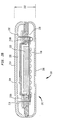
- FIG. 2A is an exploded perspective view of one embodiment of an implant device 200 in accordance with embodiments of the present invention: FIG. 2B is a cross-sectional view of the implant device illustrated in FIG. 2A taken along section line 2B-2B.
- FIG. 2C is the same cross-sectional view of the housing of the implant device illustrated in FIG. 2B ; that is, the implant device with the hermetic enclosure vacated of functional components. Implantable device 200 is described next below with reference to FIGS. 2A-2C .
- Implant device 200 comprises a hermetically-sealed container 202.
- Hermetically- sealed container 202 is formed by a bottom shell 206 hermetically connected to a chassis 204.
- container 202 defines a hermetic enclosure 224 in which functional components 212 are located.
- functional components include at least any components which are not to be exposed to biological systems, including mechanical, electrical, electro-mechanical and/or electronic components.
- functional components 212 include a printed wiring board 208 and electronic components 228 mounted on printed wiring board 208.
- electronic components 228 may comprise one or more relatively large components 228L and one or more relatively small components 228S.
- relatively larger components 228L are those having a height which is, on average, generally greater than that of other components.
- the height of functional components 212 is the dimension of the component along an axis parallel with thickness 222 of implant device 200.
- relatively smaller components 228S are those having a height which is generally less than that of other components 212.
- Container 202 further comprises at least one hermetic feedthrough 210 disposed in either chassis 204 and/or bottom shell 206.
- hermetic feedthrough 210 disposed in either chassis 204 and/or bottom shell 206.
- two elongate hermetic feedthroughs 210A and 210B are disposed in apertures 218 of chassis 204.
- Such feedthroughs 210 are each configured to permit a input/output line 216 to infiltrate hermetic enclosure 224 without degrading the hermeticity of the enclosure.
- Input/output lines 216 may be, for example, wires (copper, fiber optic, etc.), cables, tubes, etc. that facilitate the transfer of energy, data, materials, biological samples, etc. between functional components 212 and the recipient, other implantable devices, external components, etc.
- one lead 216 extends from the bottom of printed wiring board 208 through one hermetic feedthrough 210A while another lead 216 extends from the bottom of printed wiring board 208 through the other hermetic feedthrough 210B.
- one such lead 216 is connected to an internal transcutaneous transfer coil and the other lead 216 is connected to electrode array 134.
- Hermetic feedthroughs 210 allow for many input/output lines of any type to infiltrate enclosure 224, without impairing or otherwise jeopardizing the hermeticity of enclosure 224.
- Implantable device 200 has a side, referred to herein as the impact side, that is more likely to receive external forces applied to the device due to the implant orientation and location. That is, the surface of the implant device which faces toward the skin of the implant recipient is likely to receive external forces, particularly when the device is implanted close to or immediately beneath the skin. It follows, then, that an opposing side of the device is generally facing toward the interior of the recipient and, as such, is less likely to directly receive external forces which may be applied to the device.
- a top shell 214 is connected to container 202 spaced from and adjacent to the container define the noted impact side of implant device 200.
- Top shell 214 and container 202 form a non-hermetic enclosure 226 best illustrated in FIGS. 2B and 2C .
- Enclosure 226 is non-hermetic due to the presences of at least one aperture 230 ( FIG. 2A ) through which input/output lines 216 are routed to connect to other implanted or external systems, devices, etc., as noted above.
- top shell 214 may be designed to have a desired impact resistance while not requiring an increase in the size of container 202 nor resulting in a decrease in the hermeticity of enclosure 224. This is particularly beneficial in those implants which are implanted adjacent to bone immediately under a recipient's skin, such as stimulator unit 126 of hearing prosthesis 100. Such devices are subject to the greatest external forces due to their being implanted against the mastoid bone immediately beneath a recipient's scalp.
- the minimal thickness of implant devices of the present invention may reduce or eliminate the extent to which the mastoid is excavated to accommodate the implant, while increasing the impact resistance of the device.
- Top shell 214 comprises a lateral surface defining the top surface of device 200, and side walls extending generally orthogonally from the lateral surface.
- bottom shell 206 comprises a lateral surface defining the bottom surface of device 200, and side walls extending generally orthogonally from the lateral surface.
- top shell 214 and bottom shell 206 mate with opposing sides of a peripheral edge of chassis 204. It should be appreciated, however, that top and bottom shells 214, 206 may be coupled in a myriad of ways. In one alternative embodiment, for example, top and bottom shells 214, 206 directly mate with each other.
- top shell 214 is slightly convex. Applied forces will be completely or partially absorbed by top shell 214 as well as transferred along top shell 214 to chassis 204 and bottom shell 206 and, ultimately, to the adjacent mastoid bone (not shown). Should implantable device 200 experience a large external force which causes it to flex inward, functional components 212 are also protected by chassis 204. In other words, there are two layers of material protecting functional components 212 from external forces, top shell 214 and chassis 204.
- Top shell 214 may be designed to have a desired impact resistance.
- top shell 214 has a thickness that is substantially greater than the thickness of bottom shell 206.
- Such an increase in thickness need not result in a increase in size of implant device 200. Rather, it may result in a decrease in the volume of non-hermetic enclosure 226.
- top layer 214 is formed from titanium having a thickness of between approximately 0.35mm and 0.5mm. In other embodiments, the thickness of top layer 214 is between approximately 0.40mm and 0.45mm. In the same or other embodiments, the thickness of top layer 214 is approximately double the thickness of bottom layer 206.
- an inner filler material may be injected or inserted in non-hermetic enclosure 226 and/or hermetic enclosure 224.
- the inner filler material may help the structural integrity of implantable device 200 by providing additionally impact resistance.
- Suitable inner filler materials include silicon, SantopreneTM or other impact-dampening materials that will be understood by those skilled in the art.
- implantable device 200 houses a printed circuit board 208 on which relatively larger electronic components 228L and small electronic components 228S are mounted. Relatively larger electronic components 228L are mounted towards the center of printed circuit board 208 while relatively smaller electronic components 228S are mounted on the perimeter of printed circuit board 208.
- relatively larger and smaller components refers to the height of the functional component, wherein the height is the distance along the axis which is orthogonal to the plane defined by printed circuit board 208. The height of functional components, then is parallel with the thickness 222 of implantable device 200.
- Hermetic container 202 is configured such that a large volume of hermetic enclosure 224 is provided toward the center of implant device 200, providing sufficient space for functional components 212 having a relatively larger height.
- the large area may have a height of approximately 4mm to 5mm, and preferably 4.2mm to 4.5mm.
- the smaller areas are located on the perimeter of container 202, providing sufficient space to house functional components 228S having a relatively smaller height.
- the smaller areas may have a height 222 of approximately 2mm to 3mm.
- height 222 is approximately 2.4mm smaller area may have substantially the same height to provide a substantially symmetrical container 202.
- implantable device 200 has an exterior surface that is substantially smooth surface; that is, there are no discrete changes in the surface tangent of implant device 200.
- One method for achieving the smoothness of the overall shape of implant device 200 is to use a silicone material designed to take advantage of the shape of top shell 214, as illustrated in FIG. 4 .
- Top shell 214 may use a thicker layer of silicone in areas where better adhesion is desired.
- the silicone shell may have a thickness of between about 0.2mm to 0.25mm.
- FIGS. 3A and 3B show a top and bottom perspective view of one embodiment chassis 204.
- FIG. 3A shows two recesses 302 separated by web 304.
- Chassis 204 has pins 306 for aligning and/or positioning printed circuit board 208 on chassis 204.
- Feedthrough slots 218 are provided on brim 310 of chassis 204 so that feedthrough 210 may easily connect to printed circuit board when they are installed in the slots.
- a printed circuit board may rest against brim 310 so that the printed circuit board extends over feedthrough slots 218 and recesses 302.
- Chassis 204 has a lower sunken rim 312 around the edge of chassis 204 for mating with bottom shell 206 (not shown).
- FIG. 3B is a top perspective view of chassis 204 illustrates a projection 314 created by recesses 302.
- Routing guides 316 are positioned so that coil and electrode wires (not shown) may extend into feedthrough slots 218 from external sources. Routing guides 316 dictate the geometry of the coil exit, which contributes to fatigue performance.
- Top shell 214 covers projection 314 and may mate with chassis 204 on upper sunken rim 318.
- sunken rims 342, 318 provide an easy locating means for mating with the shells 214, 206 without the need for accurate jigging.
- Sunken rims 342, 318 also provide a shield against laser "shine through” which can damage internal components during mating of the shell to chassis by laser weld.
- Feedthrough slots 218 of certain embodiments of the invention provide additional benefits as well. It is well known in the art that feedthroughs are generally tightly held to the electronic components and the printed circuit board within the chassis. If the size of chassis varies, the feedthrough slot size may also be varied. An automated production process may even measure individual feedthrough slots so that a matching chassis may be manufactured. Each feedthrough slot 218 may facilitate different feedthrough configurations which increases the flexibility of chassis 204.
- chassis 204 positions and protects electronic components 228 in recesses 302.
- chassis 204 has a recess 302A that partially surrounds and houses large electronic components 228L.
- Chassis 204 has a web 304 that separates recesses 302.
- Small electronic components 228S may be mounted on printed circuit board 204.
- Recesses 320B may also partially surround and house small electronic components 228S. Additional small electronic components 228S are mounted on the non-chassis side of printed circuit board 208, and are covered by a bottom shell layer 206. This minimizes the amount of space necessary in implant 200.
- Top layer 214 may extend over chassis 202 and to create a curvature. Top layer 214 may be adhered to chassis 204 along an upper sunken rim 318, while bottom layer 206 may be adhered to chassis 204 along a lower sunken rim 312.
- Chassis 204 may have a thickness of approximately 1.6mm but may vary down to 0.25mm in some areas. Suitable materials for chassis 204 include titanium or ceramic, among others.
- chassis 204 in implant device 200 provides manufacturing, space design and impact design advantages. Such advantages may be achieved by the presence of webs 304 in chassis 204. Webs 304 serve to define recesses 302A, 302B and which electronic components 228 will be compartmentalized with other components 228, if any. Also, when receiving an impact, a web 304 may contact printed circuit board 208 to divert the impact force from electronic components 228 to the printed circuit board 208.
- a chassis may have any number of designs of recesses and webs and the design shown in FIGS. 3A and 3B is one example. For example, there may be three or more recesses, each having a different dimension. As noted, in some embodiments of the present invention, there may be an inner filler material in recesses 302 to protect components and to provide additional impact strength.
- the chassis design of certain embodiments of the present invention protects delicate circuitry and larger electronic components.
- a transformer is one of the larger components on the printed circuit board and may extend into a recess of the chassis.
- embodiments of the present invention allow the transformer to sit "in” the chassis by extending through a recess, rather than rest solely within a recess.
- Another method to conserve space is to place the transformer within an opening of the printed circuit board, so that the transformer extends into a recess and through the printed circuit board and is covered by the bottom shell.
- the integrated circuit is one of the most delicate parts of the implant, and one of the most critical in terms of functionality.
- the IC is mounted on the chassis side of the PCB, and the other components (including test points) on the other side.
- the IC may rest within a recess of the chassis for protection. Stress from impact may be redirected through the outer shell and/or to an inner filler, to the chassis and the web, and then through to the surrounding components, avoiding the IC.
- Recesses in the chassis may also house a chip insulator.
- the chassis is a complex part which locates and houses several other parts. Rather than having "complex" alignment tools or jigs, or having to locate parts by eye, this complexity is incorporated into the chassis.
- Producing a complex chassis may be done by many methods. Examples of such methods include milling, EDM, Wire EDM, coining and metal injection molding (MIM). The last two of these methods are relatively advantageous because the complexity is built into only one part (the die), rather than each part, as with milling. However, in milling, there exists the flexibility to match variations in size by changing the design by machining the complex chassis.
- the complex chassis allows electronic components to be packed in a pre-designed layout within strict tolerances which are difficult to achieve by conventional methods.
- a complex chassis may increase reliability of implants by reducing the total number of parts, and lowering logistic costs while providing physical protection to electronic components.
- having a complex chassis requires additional time to manufacture the chassis depending on the method of manufacture. For example, machining may take more time to manufacture than chassis that is MIM or coined.
- machining may take more time to manufacture than chassis that is MIM or coined.
- MIM or coined may be produced through highly consistent and reliable manufacturing methods. Machining may include milling or selective laser melting (SLM) could also be used to chassis. Cycle time for SLM would be faster than milling but slower than MIM, which is slower again than coining.
- SLM selective laser melting
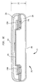
- FIG. 4 is a cross-sectional view of an alternative embodiment of implant device 200.
- a silicon layer 402 is adhered to the surface of implant device 200.
- the thickness of the silicone provides for a softer area that can be optionally used for screw fixation, as well as giving a soft feeling of the edges of the implant through the skin, due to the flexibility of top shell 214.
- Such an area may be used for securing a fixation plate (not shown) through a silicone boot.
- the fixation plate may be designed to fit the curvature of top shell 214.
- Fixation plate 110 provides a means for securing a screw to a recipient's bone. It should be appreciated that any quantity of fixation plates or other fasteners and pins may be used to secure implant device 200 to the recipient.
Landscapes
- Health & Medical Sciences (AREA)
- Otolaryngology (AREA)
- Engineering & Computer Science (AREA)
- Biomedical Technology (AREA)
- Nuclear Medicine, Radiotherapy & Molecular Imaging (AREA)
- Radiology & Medical Imaging (AREA)
- Life Sciences & Earth Sciences (AREA)
- Animal Behavior & Ethology (AREA)
- General Health & Medical Sciences (AREA)
- Public Health (AREA)
- Veterinary Medicine (AREA)
- Prostheses (AREA)
- Electrotherapy Devices (AREA)
Claims (20)
- Dispositif implantable (200) configuré en vue d'une implantation en dessous de la peau d'un receveur, le dispositif implantable comprenant :une coque supérieure (214) comportant une surface d'impact en vue d'un positionnement vers ladite peau du receveur et des parois latérales s'étendant globalement orthogonalement depuis la périphérie de la surface d'impact, au moins une partie de la coque supérieure étant exposée à l'environnement externe du dispositif implantable,une coque inférieure (206) comportant une seconde partie de surface en vue d'un positionnement à distance de ladite peau du receveur, ladite seconde partie de surface étant globalement parallèle à des parties de ladite surface d'impact de ladite coque supérieure, et comportant des parois latérales s'étendant globalement orthogonalement depuis la périphérie de celle-ci vers ladite coque supérieure pour former une enveloppe non hermétique entre lesdites coques supérieure et inférieure,un châssis (204) immobilisé sur ladite coque inférieure, etau moins un composant fonctionnel (212),caractérisé en ce queledit châssis est placé à l'intérieur de ladite enveloppe non hermétique pour former une enveloppe hermétique avec ladite coque inférieure, ledit composant fonctionnel étant placé dans ladite enveloppe hermétique.
- Dispositif implantable selon la revendication 1, dans lequel lesdites parois latérales de ladite coque supérieure et lesdites parois latérales de ladite coque inférieure s'accouplent avec les côtés en opposition dudit châssis.
- Dispositif implantable selon la revendication 1, dans lequel ledit ou lesdits composants fonctionnels sont immobilisés sur ledit châssis.
- Dispositif implantable selon la revendication 1, comprenant en outre une traversée hermétique disposée dans un ou plusieurs de ladite coque inférieure et dudit châssis, configurée pour autoriser au moins une ligne d'entrée / sortie à pénétrer à l'intérieur de ladite enveloppe hermétique.
- Dispositif implantable selon la revendication 1, dans lequel ledit ou lesdits composants fonctionnels comprennent une pluralité de composants fonctionnels de diverses dimensions positionnés à l'intérieur de ladite enveloppe hermétique de telle sorte que les composants fonctionnels présentant une hauteur relativement grande sont logés ensembles dans la zone centrale de ladite enveloppe hermétique alors que les composants fonctionnels présentant une hauteur relativement plus petite sont logés dans une ou plusieurs zones périphériques de ladite enveloppe hermétique.
- Dispositif implantable selon la revendication 1, dans lequel ladite surface d'impact de ladite coque supérieure est convexe.
- Dispositif implantable selon la revendication 1, dans lequel le châssis comporte au moins un évidement, dimensionné pour recevoir fonctionnellement un ou plusieurs dudit ou desdits composants fonctionnels.
- Dispositif implantable selon la revendication 1, dans lequel ladite coque supérieure définit au moins partiellement une ouverture ou plus, chacune de ladite ou desdites ouvertures étant configurée pour permettre à au moins une ligne d'entrée / sortie de s'étendre à partir dudit dispositif implantable.
- Dispositif implantable selon la revendication 1, dans lequel ledit ou lesdits composants fonctionnels comprennent :une carte à circuit imprimé comprenant une carte de câblage imprimée comportant des composants électroniques montés sur celle-ci.
- Dispositif implantable selon la revendication 1, dans lequel ladite pluralité de composants fonctionnels est positionnée à l'intérieur de ladite enveloppe hermétique de telle sorte que les composants fonctionnels présentant une hauteur relativement grande sont logés ensembles dans une zone centrale de ladite enveloppe hermétique alors que les composants fonctionnels présentant une hauteur relativement plus petite sont logés dans une ou plusieurs zones périphériques de ladite enveloppe hermétique.
- Dispositif implantable selon la revendication 1, dans lequel ladite coque supérieure est reliée à ladite enveloppe hermétique de telle sorte que les forces d'impact appliquées à ladite coque supérieure sont transférées à ladite coque inférieure.
- Dispositif implantable selon la revendication 1, dans lequel ladite seconde coque présente une surface extérieure s'incurvant de manière continue.
- Dispositif implantable selon la revendication 1, dans lequel ladite coque inférieure présente une première épaisseur et ladite coque supérieure présente une seconde épaisseur, différente de ladite première épaisseur.
- Dispositif implantable selon la revendication 1, dans lequel ledit dispositif est un composant faisant partie d'un implant auditif prothétique, ledit ou lesdits composants fonctionnels comprenant une pluralité de composants fonctionnels appartenant à une unité formant stimulateur / récepteur et au moins un câble configuré pour transporter des signaux électroniques entre ledit dispositif implantable et un ou plusieurs d'une bobine transcutanée et d'un réseau d'électrodes.
- Prothèse auditive comprenant :un dispositif implantable décrit dans l'une quelconque des revendications précédentes.
- Prothèse auditive selon la revendication 15, dans laquelle ledit dispositif implantable comprend une unité formant stimulateur / récepteur de ladite prothèse auditive.
- Prothèse auditive selon la revendication 15, dans laquelle ledit dispositif implantable comprend un processeur de parole de ladite prothèse auditive.
- Prothèse auditive selon la revendication 15, dans laquelle ledit dispositif implantable comprend pratiquement tous les composants fonctionnels de ladite prothèse auditive.
- Dispositif implantable selon l'une quelconque des revendications précédentes, dans lequel l'enveloppe non hermétique est remplie d'un matériau d'amortissement d'impact.
- Dispositif implantable selon l'une quelconque des revendications 1 à 14, dans lequel le châssis est immobilisé sur ladite coque supérieure.
Applications Claiming Priority (2)
| Application Number | Priority Date | Filing Date | Title |
|---|---|---|---|
| US64698805P | 2005-01-27 | 2005-01-27 | |
| PCT/US2006/002794 WO2006081361A2 (fr) | 2005-01-27 | 2006-01-27 | Dispositif medical implantable |
Publications (3)
| Publication Number | Publication Date |
|---|---|
| EP1846089A2 EP1846089A2 (fr) | 2007-10-24 |
| EP1846089A4 EP1846089A4 (fr) | 2010-06-09 |
| EP1846089B1 true EP1846089B1 (fr) | 2016-08-31 |
Family
ID=36741049
Family Applications (1)
| Application Number | Title | Priority Date | Filing Date |
|---|---|---|---|
| EP06719594.1A Active EP1846089B1 (fr) | 2005-01-27 | 2006-01-27 | Dispositif medical implantable |
Country Status (6)
| Country | Link |
|---|---|
| US (1) | US8885837B2 (fr) |
| EP (1) | EP1846089B1 (fr) |
| JP (2) | JP5088788B2 (fr) |
| AU (1) | AU2006209223B2 (fr) |
| CA (1) | CA2595887A1 (fr) |
| WO (1) | WO2006081361A2 (fr) |
Families Citing this family (26)
| Publication number | Priority date | Publication date | Assignee | Title |
|---|---|---|---|---|
| AU2006209223B2 (en) | 2005-01-27 | 2012-04-12 | Cochlear Limited | Implantable medical device |
| WO2008128300A1 (fr) | 2007-04-23 | 2008-10-30 | Cochlear Limited | Ensemble d'implant |
| US8612012B2 (en) | 2007-07-02 | 2013-12-17 | Cochlear Limited | Implantable housing assembly |
| WO2009009827A1 (fr) | 2007-07-17 | 2009-01-22 | Cochlear Limited | Procédé et appareil pour former une structure électriquement isolante ayant des trous d'interconnexion |
| CN101801454A (zh) * | 2007-09-10 | 2010-08-11 | Med-El电气医疗器械有限公司 | 用于植入物的冲击防护 |
| US9907963B2 (en) | 2007-11-30 | 2018-03-06 | Med-El Elektromedizinische Geraete Gmbh | Impact protector for an external element of a partially implantable system |
| US8216287B2 (en) | 2008-03-31 | 2012-07-10 | Cochlear Limited | Tangential force resistant coupling for a prosthetic device |
| US8538530B1 (en) | 2008-11-19 | 2013-09-17 | Advanced Bionics | Hermetically sealed feedthrough case |
| AU2009344197A1 (en) * | 2009-04-08 | 2011-12-01 | Saluda Medical Pty Limited | Bonded hermetic feed through for an active implantable medical device |
| WO2010138911A1 (fr) | 2009-05-29 | 2010-12-02 | Otologics, Llc | Procédé et système de stimulation auditive implantable avec microphones implantés décalés |
| US8386047B2 (en) | 2010-07-15 | 2013-02-26 | Advanced Bionics | Implantable hermetic feedthrough |
| US8552311B2 (en) | 2010-07-15 | 2013-10-08 | Advanced Bionics | Electrical feedthrough assembly |
| US9056204B2 (en) | 2010-10-29 | 2015-06-16 | Cochlear Limited | Universal implant |
| US20120197345A1 (en) * | 2011-01-28 | 2012-08-02 | Med-El Elektromedizinische Geraete Gmbh | Medical Device User Interface |
| US8515540B2 (en) | 2011-02-24 | 2013-08-20 | Cochlear Limited | Feedthrough having a non-linear conductor |
| US9078070B2 (en) | 2011-05-24 | 2015-07-07 | Analog Devices, Inc. | Hearing instrument controller |
| EP2841155B1 (fr) * | 2012-04-27 | 2020-01-22 | Medtronic Inc. | Dispositif implantable comprenant un élément de châssis |
| US20140163626A1 (en) | 2012-12-12 | 2014-06-12 | Grahame Walling | Implantable device migration control |
| CN104869888B (zh) * | 2012-12-21 | 2017-12-19 | 微芯片生物技术公司 | 用于微创插入的可植入医疗装置 |
| US9998837B2 (en) | 2014-04-29 | 2018-06-12 | Cochlear Limited | Percutaneous vibration conductor |
| WO2016118127A1 (fr) * | 2015-01-21 | 2016-07-28 | Advanced Bionics Ag | Implants cochléaires |
| USD760392S1 (en) * | 2015-06-26 | 2016-06-28 | Cochlear Limited | External component of a hearing prosthesis |
| US11071869B2 (en) | 2016-02-24 | 2021-07-27 | Cochlear Limited | Implantable device having removable portion |
| US11850417B2 (en) | 2016-12-15 | 2023-12-26 | Cochlear Limited | Feedthrough placement |
| FR3089423B1 (fr) | 2018-12-07 | 2020-12-18 | Commissariat Energie Atomique | Dispositif médical implantable à architecture améliorée |
| CN116113471A (zh) * | 2020-08-13 | 2023-05-12 | 心脏起搏器股份公司 | 具有相对运动控制的可植入医疗装置 |
Family Cites Families (15)
| Publication number | Priority date | Publication date | Assignee | Title |
|---|---|---|---|---|
| US5085628A (en) * | 1988-09-09 | 1992-02-04 | Storz Instrument Company | Implantable hearing aid coupler device |
| DE4104358A1 (de) * | 1991-02-13 | 1992-08-20 | Implex Gmbh | Implantierbares hoergeraet zur anregung des innenohres |
| US5782891A (en) * | 1994-06-16 | 1998-07-21 | Medtronic, Inc. | Implantable ceramic enclosure for pacing, neurological, and other medical applications in the human body |
| WO1995034342A1 (fr) | 1994-06-16 | 1995-12-21 | Medtronic, Inc. | Boitier en ceramique pour dispositif implantable |
| US5859916A (en) | 1996-07-12 | 1999-01-12 | Symphonix Devices, Inc. | Two stage implantable microphone |
| DE19638159C2 (de) | 1996-09-18 | 2000-09-07 | Implex Hear Tech Ag | Vollständig implantierbare Hörhilfe zur elektrischen Anregung des Gehörs |
| US5814095A (en) * | 1996-09-18 | 1998-09-29 | Implex Gmbh Spezialhorgerate | Implantable microphone and implantable hearing aids utilizing same |
| US6093144A (en) * | 1997-12-16 | 2000-07-25 | Symphonix Devices, Inc. | Implantable microphone having improved sensitivity and frequency response |
| US6477037B1 (en) * | 1998-04-03 | 2002-11-05 | Medtronic, Inc. | Implantable medical device having flat electrolytic capacitor with miniaturized epoxy connector droplet |
| DE19840211C1 (de) | 1998-09-03 | 1999-12-30 | Implex Hear Tech Ag | Wandler für teil- oder vollimplantierbare Hörgeräte |
| DE10041727C2 (de) * | 2000-08-25 | 2003-04-10 | Cochlear Ltd | Implantierbares hermetisch dichtes Gehäuse für eine implantierbare medizinische Vorrichtung |
| US6975906B2 (en) | 2001-02-08 | 2005-12-13 | Wilson Greatbatch Ltd. | One piece header assembly over molded to an implantable medical device |
| US7204799B2 (en) * | 2003-11-07 | 2007-04-17 | Otologics, Llc | Microphone optimized for implant use |
| AU2006209223B2 (en) | 2005-01-27 | 2012-04-12 | Cochlear Limited | Implantable medical device |
| US8515540B2 (en) * | 2011-02-24 | 2013-08-20 | Cochlear Limited | Feedthrough having a non-linear conductor |
-
2006
- 2006-01-27 AU AU2006209223A patent/AU2006209223B2/en not_active Ceased
- 2006-01-27 US US11/814,507 patent/US8885837B2/en active Active
- 2006-01-27 EP EP06719594.1A patent/EP1846089B1/fr active Active
- 2006-01-27 JP JP2007553228A patent/JP5088788B2/ja not_active Expired - Fee Related
- 2006-01-27 WO PCT/US2006/002794 patent/WO2006081361A2/fr active Search and Examination
- 2006-01-27 CA CA002595887A patent/CA2595887A1/fr not_active Abandoned
-
2012
- 2012-03-08 JP JP2012051723A patent/JP5277330B2/ja not_active Expired - Fee Related
Also Published As
| Publication number | Publication date |
|---|---|
| AU2006209223B2 (en) | 2012-04-12 |
| WO2006081361A2 (fr) | 2006-08-03 |
| AU2006209223A1 (en) | 2006-08-03 |
| JP2008528191A (ja) | 2008-07-31 |
| US20090034769A1 (en) | 2009-02-05 |
| EP1846089A4 (fr) | 2010-06-09 |
| CA2595887A1 (fr) | 2006-08-03 |
| JP5277330B2 (ja) | 2013-08-28 |
| JP2012143576A (ja) | 2012-08-02 |
| EP1846089A2 (fr) | 2007-10-24 |
| WO2006081361A3 (fr) | 2007-04-19 |
| JP5088788B2 (ja) | 2012-12-05 |
| US8885837B2 (en) | 2014-11-11 |
Similar Documents
| Publication | Publication Date | Title |
|---|---|---|
| EP1846089B1 (fr) | Dispositif medical implantable | |
| US11577078B2 (en) | Implantable auditory stimulation system and method with offset implanted microphones | |
| US8019436B2 (en) | Electrode assembly for a stimulating medical device | |
| US6648914B2 (en) | Totally implantable cochlear prosthesis | |
| US20060079950A1 (en) | Cochlear endosteal electrode carrier member | |
| US7587248B2 (en) | Implantable prosthetic device | |
| US7937154B2 (en) | Promoting curvature and maintaining orientation of an electrode carrier member of a stimulating medical device | |
| EP2296750A1 (fr) | Capteur de son implantable pour prothèses auditives | |
| US20210330964A1 (en) | Implantable device migration control | |
| US10940320B2 (en) | Distributed implantable hearing systems | |
| US11889670B2 (en) | Electromagnetic interference shielding of MEMS microphone via printed circuit board | |
| US11896835B2 (en) | Electrical shielding in implantable medical devices | |
| EP4271469A1 (fr) | Support implantable pour implant médical |
Legal Events
| Date | Code | Title | Description |
|---|---|---|---|
| PUAI | Public reference made under article 153(3) epc to a published international application that has entered the european phase |
Free format text: ORIGINAL CODE: 0009012 |
|
| 17P | Request for examination filed |
Effective date: 20070816 |
|
| AK | Designated contracting states |
Kind code of ref document: A2 Designated state(s): AT BE BG CH CY CZ DE DK EE ES FI FR GB GR HU IE IS IT LI LT LU LV MC NL PL PT RO SE SI SK TR |
|
| AX | Request for extension of the european patent |
Extension state: AL BA HR MK YU |
|
| DAX | Request for extension of the european patent (deleted) | ||
| A4 | Supplementary search report drawn up and despatched |
Effective date: 20100511 |
|
| RIC1 | Information provided on ipc code assigned before grant |
Ipc: A61N 1/00 20060101AFI20110228BHEP |
|
| 17Q | First examination report despatched |
Effective date: 20110310 |
|
| RAP1 | Party data changed (applicant data changed or rights of an application transferred) |
Owner name: COCHLEAR LIMITED |
|
| GRAP | Despatch of communication of intention to grant a patent |
Free format text: ORIGINAL CODE: EPIDOSNIGR1 |
|
| INTG | Intention to grant announced |
Effective date: 20160308 |
|
| GRAS | Grant fee paid |
Free format text: ORIGINAL CODE: EPIDOSNIGR3 |
|
| GRAA | (expected) grant |
Free format text: ORIGINAL CODE: 0009210 |
|
| AK | Designated contracting states |
Kind code of ref document: B1 Designated state(s): AT BE BG CH CY CZ DE DK EE ES FI FR GB GR HU IE IS IT LI LT LU LV MC NL PL PT RO SE SI SK TR |
|
| REG | Reference to a national code |
Ref country code: CH Ref legal event code: EP Ref country code: GB Ref legal event code: FG4D |
|
| REG | Reference to a national code |
Ref country code: IE Ref legal event code: FG4D |
|
| REG | Reference to a national code |
Ref country code: DE Ref legal event code: R096 Ref document number: 602006050116 Country of ref document: DE |
|
| REG | Reference to a national code |
Ref country code: AT Ref legal event code: REF Ref document number: 824454 Country of ref document: AT Kind code of ref document: T Effective date: 20161015 |
|
| REG | Reference to a national code |
Ref country code: LT Ref legal event code: MG4D |
|
| REG | Reference to a national code |
Ref country code: FR Ref legal event code: PLFP Year of fee payment: 12 |
|
| REG | Reference to a national code |
Ref country code: NL Ref legal event code: MP Effective date: 20160831 |
|
| PG25 | Lapsed in a contracting state [announced via postgrant information from national office to epo] |
Ref country code: LT Free format text: LAPSE BECAUSE OF FAILURE TO SUBMIT A TRANSLATION OF THE DESCRIPTION OR TO PAY THE FEE WITHIN THE PRESCRIBED TIME-LIMIT Effective date: 20160831 Ref country code: FI Free format text: LAPSE BECAUSE OF FAILURE TO SUBMIT A TRANSLATION OF THE DESCRIPTION OR TO PAY THE FEE WITHIN THE PRESCRIBED TIME-LIMIT Effective date: 20160831 |
|
| PG25 | Lapsed in a contracting state [announced via postgrant information from national office to epo] |
Ref country code: LV Free format text: LAPSE BECAUSE OF FAILURE TO SUBMIT A TRANSLATION OF THE DESCRIPTION OR TO PAY THE FEE WITHIN THE PRESCRIBED TIME-LIMIT Effective date: 20160831 Ref country code: GR Free format text: LAPSE BECAUSE OF FAILURE TO SUBMIT A TRANSLATION OF THE DESCRIPTION OR TO PAY THE FEE WITHIN THE PRESCRIBED TIME-LIMIT Effective date: 20161201 Ref country code: SE Free format text: LAPSE BECAUSE OF FAILURE TO SUBMIT A TRANSLATION OF THE DESCRIPTION OR TO PAY THE FEE WITHIN THE PRESCRIBED TIME-LIMIT Effective date: 20160831 Ref country code: NL Free format text: LAPSE BECAUSE OF FAILURE TO SUBMIT A TRANSLATION OF THE DESCRIPTION OR TO PAY THE FEE WITHIN THE PRESCRIBED TIME-LIMIT Effective date: 20160831 Ref country code: ES Free format text: LAPSE BECAUSE OF FAILURE TO SUBMIT A TRANSLATION OF THE DESCRIPTION OR TO PAY THE FEE WITHIN THE PRESCRIBED TIME-LIMIT Effective date: 20160831 |
|
| PG25 | Lapsed in a contracting state [announced via postgrant information from national office to epo] |
Ref country code: EE Free format text: LAPSE BECAUSE OF FAILURE TO SUBMIT A TRANSLATION OF THE DESCRIPTION OR TO PAY THE FEE WITHIN THE PRESCRIBED TIME-LIMIT Effective date: 20160831 Ref country code: RO Free format text: LAPSE BECAUSE OF FAILURE TO SUBMIT A TRANSLATION OF THE DESCRIPTION OR TO PAY THE FEE WITHIN THE PRESCRIBED TIME-LIMIT Effective date: 20160831 |
|
| PG25 | Lapsed in a contracting state [announced via postgrant information from national office to epo] |
Ref country code: CZ Free format text: LAPSE BECAUSE OF FAILURE TO SUBMIT A TRANSLATION OF THE DESCRIPTION OR TO PAY THE FEE WITHIN THE PRESCRIBED TIME-LIMIT Effective date: 20160831 Ref country code: DK Free format text: LAPSE BECAUSE OF FAILURE TO SUBMIT A TRANSLATION OF THE DESCRIPTION OR TO PAY THE FEE WITHIN THE PRESCRIBED TIME-LIMIT Effective date: 20160831 Ref country code: SK Free format text: LAPSE BECAUSE OF FAILURE TO SUBMIT A TRANSLATION OF THE DESCRIPTION OR TO PAY THE FEE WITHIN THE PRESCRIBED TIME-LIMIT Effective date: 20160831 Ref country code: BG Free format text: LAPSE BECAUSE OF FAILURE TO SUBMIT A TRANSLATION OF THE DESCRIPTION OR TO PAY THE FEE WITHIN THE PRESCRIBED TIME-LIMIT Effective date: 20161130 Ref country code: PT Free format text: LAPSE BECAUSE OF FAILURE TO SUBMIT A TRANSLATION OF THE DESCRIPTION OR TO PAY THE FEE WITHIN THE PRESCRIBED TIME-LIMIT Effective date: 20170102 Ref country code: BE Free format text: LAPSE BECAUSE OF FAILURE TO SUBMIT A TRANSLATION OF THE DESCRIPTION OR TO PAY THE FEE WITHIN THE PRESCRIBED TIME-LIMIT Effective date: 20160831 Ref country code: PL Free format text: LAPSE BECAUSE OF FAILURE TO SUBMIT A TRANSLATION OF THE DESCRIPTION OR TO PAY THE FEE WITHIN THE PRESCRIBED TIME-LIMIT Effective date: 20160831 |
|
| REG | Reference to a national code |
Ref country code: DE Ref legal event code: R097 Ref document number: 602006050116 Country of ref document: DE |
|
| PG25 | Lapsed in a contracting state [announced via postgrant information from national office to epo] |
Ref country code: IT Free format text: LAPSE BECAUSE OF FAILURE TO SUBMIT A TRANSLATION OF THE DESCRIPTION OR TO PAY THE FEE WITHIN THE PRESCRIBED TIME-LIMIT Effective date: 20160831 |
|
| PLBE | No opposition filed within time limit |
Free format text: ORIGINAL CODE: 0009261 |
|
| STAA | Information on the status of an ep patent application or granted ep patent |
Free format text: STATUS: NO OPPOSITION FILED WITHIN TIME LIMIT |
|
| 26N | No opposition filed |
Effective date: 20170601 |
|
| PG25 | Lapsed in a contracting state [announced via postgrant information from national office to epo] |
Ref country code: SI Free format text: LAPSE BECAUSE OF FAILURE TO SUBMIT A TRANSLATION OF THE DESCRIPTION OR TO PAY THE FEE WITHIN THE PRESCRIBED TIME-LIMIT Effective date: 20160831 |
|
| REG | Reference to a national code |
Ref country code: CH Ref legal event code: PL |
|
| GBPC | Gb: european patent ceased through non-payment of renewal fee |
Effective date: 20170127 |
|
| PG25 | Lapsed in a contracting state [announced via postgrant information from national office to epo] |
Ref country code: MC Free format text: LAPSE BECAUSE OF FAILURE TO SUBMIT A TRANSLATION OF THE DESCRIPTION OR TO PAY THE FEE WITHIN THE PRESCRIBED TIME-LIMIT Effective date: 20160831 |
|
| PG25 | Lapsed in a contracting state [announced via postgrant information from national office to epo] |
Ref country code: CH Free format text: LAPSE BECAUSE OF NON-PAYMENT OF DUE FEES Effective date: 20170131 Ref country code: LI Free format text: LAPSE BECAUSE OF NON-PAYMENT OF DUE FEES Effective date: 20170131 |
|
| REG | Reference to a national code |
Ref country code: IE Ref legal event code: MM4A |
|
| PG25 | Lapsed in a contracting state [announced via postgrant information from national office to epo] |
Ref country code: LU Free format text: LAPSE BECAUSE OF NON-PAYMENT OF DUE FEES Effective date: 20170127 Ref country code: GB Free format text: LAPSE BECAUSE OF NON-PAYMENT OF DUE FEES Effective date: 20170127 |
|
| REG | Reference to a national code |
Ref country code: FR Ref legal event code: PLFP Year of fee payment: 13 |
|
| PG25 | Lapsed in a contracting state [announced via postgrant information from national office to epo] |
Ref country code: IE Free format text: LAPSE BECAUSE OF NON-PAYMENT OF DUE FEES Effective date: 20170127 |
|
| REG | Reference to a national code |
Ref country code: AT Ref legal event code: UEP Ref document number: 824454 Country of ref document: AT Kind code of ref document: T Effective date: 20160831 |
|
| PGFP | Annual fee paid to national office [announced via postgrant information from national office to epo] |
Ref country code: AT Payment date: 20190109 Year of fee payment: 14 |
|
| PG25 | Lapsed in a contracting state [announced via postgrant information from national office to epo] |
Ref country code: HU Free format text: LAPSE BECAUSE OF FAILURE TO SUBMIT A TRANSLATION OF THE DESCRIPTION OR TO PAY THE FEE WITHIN THE PRESCRIBED TIME-LIMIT; INVALID AB INITIO Effective date: 20060127 |
|
| PG25 | Lapsed in a contracting state [announced via postgrant information from national office to epo] |
Ref country code: CY Free format text: LAPSE BECAUSE OF NON-PAYMENT OF DUE FEES Effective date: 20160831 |
|
| PG25 | Lapsed in a contracting state [announced via postgrant information from national office to epo] |
Ref country code: TR Free format text: LAPSE BECAUSE OF FAILURE TO SUBMIT A TRANSLATION OF THE DESCRIPTION OR TO PAY THE FEE WITHIN THE PRESCRIBED TIME-LIMIT Effective date: 20160831 |
|
| PG25 | Lapsed in a contracting state [announced via postgrant information from national office to epo] |
Ref country code: IS Free format text: LAPSE BECAUSE OF FAILURE TO SUBMIT A TRANSLATION OF THE DESCRIPTION OR TO PAY THE FEE WITHIN THE PRESCRIBED TIME-LIMIT Effective date: 20161231 |
|
| REG | Reference to a national code |
Ref country code: AT Ref legal event code: MM01 Ref document number: 824454 Country of ref document: AT Kind code of ref document: T Effective date: 20200127 |
|
| PG25 | Lapsed in a contracting state [announced via postgrant information from national office to epo] |
Ref country code: AT Free format text: LAPSE BECAUSE OF NON-PAYMENT OF DUE FEES Effective date: 20200127 |
|
| PGFP | Annual fee paid to national office [announced via postgrant information from national office to epo] |
Ref country code: FR Payment date: 20230110 Year of fee payment: 18 |
|
| PGFP | Annual fee paid to national office [announced via postgrant information from national office to epo] |
Ref country code: DE Payment date: 20221229 Year of fee payment: 18 |
|
| P01 | Opt-out of the competence of the unified patent court (upc) registered |
Effective date: 20230505 |