EP1845865B1 - Dispositif destine a la reparation de defauts dans les tissus mous - Google Patents
Dispositif destine a la reparation de defauts dans les tissus mous Download PDFInfo
- Publication number
- EP1845865B1 EP1845865B1 EP05854620A EP05854620A EP1845865B1 EP 1845865 B1 EP1845865 B1 EP 1845865B1 EP 05854620 A EP05854620 A EP 05854620A EP 05854620 A EP05854620 A EP 05854620A EP 1845865 B1 EP1845865 B1 EP 1845865B1
- Authority
- EP
- European Patent Office
- Prior art keywords
- bioabsorbable
- sheet
- web
- plug
- hollow members
- Prior art date
- Legal status (The legal status is an assumption and is not a legal conclusion. Google has not performed a legal analysis and makes no representation as to the accuracy of the status listed.)
- Active
Links
- 230000008439 repair process Effects 0.000 title claims abstract description 25
- 230000007547 defect Effects 0.000 title abstract description 20
- 210000004872 soft tissue Anatomy 0.000 title description 3
- 239000000463 material Substances 0.000 claims abstract description 168
- 239000002131 composite material Substances 0.000 claims abstract description 24
- 229920000954 Polyglycolide Polymers 0.000 claims description 20
- 206010019909 Hernia Diseases 0.000 claims description 19
- 229920001577 copolymer Polymers 0.000 claims description 11
- 229920000295 expanded polytetrafluoroethylene Polymers 0.000 claims description 3
- YFHICDDUDORKJB-UHFFFAOYSA-N trimethylene carbonate Chemical compound O=C1OCCCO1 YFHICDDUDORKJB-UHFFFAOYSA-N 0.000 claims description 3
- 239000004633 polyglycolic acid Substances 0.000 claims 1
- 238000003780 insertion Methods 0.000 abstract description 8
- 230000037431 insertion Effects 0.000 abstract description 8
- 208000029836 Inguinal Hernia Diseases 0.000 abstract description 5
- 210000001519 tissue Anatomy 0.000 description 21
- -1 polypropylene Polymers 0.000 description 19
- 238000004873 anchoring Methods 0.000 description 12
- 239000000853 adhesive Substances 0.000 description 11
- 230000001070 adhesive effect Effects 0.000 description 11
- 238000010276 construction Methods 0.000 description 9
- 238000000034 method Methods 0.000 description 9
- XAGFODPZIPBFFR-UHFFFAOYSA-N aluminium Chemical compound [Al] XAGFODPZIPBFFR-UHFFFAOYSA-N 0.000 description 8
- 229910052782 aluminium Inorganic materials 0.000 description 8
- 229920001343 polytetrafluoroethylene Polymers 0.000 description 8
- 239000004810 polytetrafluoroethylene Substances 0.000 description 8
- 238000005096 rolling process Methods 0.000 description 7
- CSCPPACGZOOCGX-UHFFFAOYSA-N Acetone Chemical compound CC(C)=O CSCPPACGZOOCGX-UHFFFAOYSA-N 0.000 description 6
- 229920000728 polyester Polymers 0.000 description 6
- 239000004743 Polypropylene Substances 0.000 description 5
- 238000005520 cutting process Methods 0.000 description 5
- 230000035876 healing Effects 0.000 description 5
- 239000007943 implant Substances 0.000 description 5
- 229920001155 polypropylene Polymers 0.000 description 5
- 239000011148 porous material Substances 0.000 description 5
- 239000000047 product Substances 0.000 description 5
- 230000004044 response Effects 0.000 description 5
- 238000003466 welding Methods 0.000 description 5
- 230000003466 anti-cipated effect Effects 0.000 description 4
- 229920000642 polymer Polymers 0.000 description 4
- 230000008569 process Effects 0.000 description 4
- 229910001220 stainless steel Inorganic materials 0.000 description 4
- 239000010935 stainless steel Substances 0.000 description 4
- RKDVKSZUMVYZHH-UHFFFAOYSA-N 1,4-dioxane-2,5-dione Chemical compound O=C1COC(=O)CO1 RKDVKSZUMVYZHH-UHFFFAOYSA-N 0.000 description 3
- 229920002313 fluoropolymer Polymers 0.000 description 3
- 239000004811 fluoropolymer Substances 0.000 description 3
- 238000004519 manufacturing process Methods 0.000 description 3
- 230000000452 restraining effect Effects 0.000 description 3
- 229920002799 BoPET Polymers 0.000 description 2
- 239000004698 Polyethylene Substances 0.000 description 2
- 230000009286 beneficial effect Effects 0.000 description 2
- 239000011230 binding agent Substances 0.000 description 2
- 239000012620 biological material Substances 0.000 description 2
- 210000001124 body fluid Anatomy 0.000 description 2
- 239000010839 body fluid Substances 0.000 description 2
- 235000019504 cigarettes Nutrition 0.000 description 2
- 238000001125 extrusion Methods 0.000 description 2
- 239000004744 fabric Substances 0.000 description 2
- 239000000945 filler Substances 0.000 description 2
- 238000002513 implantation Methods 0.000 description 2
- 230000002757 inflammatory effect Effects 0.000 description 2
- 230000007774 longterm Effects 0.000 description 2
- 239000000155 melt Substances 0.000 description 2
- 230000005012 migration Effects 0.000 description 2
- 238000013508 migration Methods 0.000 description 2
- 239000000203 mixture Substances 0.000 description 2
- 229920000573 polyethylene Polymers 0.000 description 2
- 238000009958 sewing Methods 0.000 description 2
- 229920000428 triblock copolymer Polymers 0.000 description 2
- 229920000742 Cotton Polymers 0.000 description 1
- AEMRFAOFKBGASW-UHFFFAOYSA-N Glycolic acid Polymers OCC(O)=O AEMRFAOFKBGASW-UHFFFAOYSA-N 0.000 description 1
- 229920000544 Gore-Tex Polymers 0.000 description 1
- 229920002302 Nylon 6,6 Polymers 0.000 description 1
- 239000004952 Polyamide Substances 0.000 description 1
- 208000031737 Tissue Adhesions Diseases 0.000 description 1
- 150000001336 alkenes Chemical class 0.000 description 1
- 239000003242 anti bacterial agent Substances 0.000 description 1
- 229940088710 antibiotic agent Drugs 0.000 description 1
- 239000004599 antimicrobial Substances 0.000 description 1
- 230000004888 barrier function Effects 0.000 description 1
- 239000012867 bioactive agent Substances 0.000 description 1
- 230000015572 biosynthetic process Effects 0.000 description 1
- 229920001400 block copolymer Polymers 0.000 description 1
- 239000006227 byproduct Substances 0.000 description 1
- 230000008859 change Effects 0.000 description 1
- 238000006243 chemical reaction Methods 0.000 description 1
- 239000011248 coating agent Substances 0.000 description 1
- 238000000576 coating method Methods 0.000 description 1
- 238000011109 contamination Methods 0.000 description 1
- 238000001816 cooling Methods 0.000 description 1
- 238000013461 design Methods 0.000 description 1
- 239000003814 drug Substances 0.000 description 1
- 230000000694 effects Effects 0.000 description 1
- 230000002068 genetic effect Effects 0.000 description 1
- 229920001519 homopolymer Polymers 0.000 description 1
- 230000007062 hydrolysis Effects 0.000 description 1
- 238000006460 hydrolysis reaction Methods 0.000 description 1
- JJTUDXZGHPGLLC-UHFFFAOYSA-N lactide Chemical compound CC1OC(=O)C(C)OC1=O JJTUDXZGHPGLLC-UHFFFAOYSA-N 0.000 description 1
- 230000014759 maintenance of location Effects 0.000 description 1
- 238000010128 melt processing Methods 0.000 description 1
- 238000002156 mixing Methods 0.000 description 1
- 238000012986 modification Methods 0.000 description 1
- 230000004048 modification Effects 0.000 description 1
- 230000000144 pharmacologic effect Effects 0.000 description 1
- 229920002647 polyamide Polymers 0.000 description 1
- 229920000139 polyethylene terephthalate Polymers 0.000 description 1
- 239000005020 polyethylene terephthalate Substances 0.000 description 1
- 229920000166 polytrimethylene carbonate Polymers 0.000 description 1
- 238000007634 remodeling Methods 0.000 description 1
- 239000002904 solvent Substances 0.000 description 1
- 239000007858 starting material Substances 0.000 description 1
- 239000000126 substance Substances 0.000 description 1
- 238000001356 surgical procedure Methods 0.000 description 1
- 239000003356 suture material Substances 0.000 description 1
- 230000017423 tissue regeneration Effects 0.000 description 1
- 238000009966 trimming Methods 0.000 description 1
Images


Classifications
-
- A—HUMAN NECESSITIES
- A61—MEDICAL OR VETERINARY SCIENCE; HYGIENE
- A61F—FILTERS IMPLANTABLE INTO BLOOD VESSELS; PROSTHESES; DEVICES PROVIDING PATENCY TO, OR PREVENTING COLLAPSING OF, TUBULAR STRUCTURES OF THE BODY, e.g. STENTS; ORTHOPAEDIC, NURSING OR CONTRACEPTIVE DEVICES; FOMENTATION; TREATMENT OR PROTECTION OF EYES OR EARS; BANDAGES, DRESSINGS OR ABSORBENT PADS; FIRST-AID KITS
- A61F2/00—Filters implantable into blood vessels; Prostheses, i.e. artificial substitutes or replacements for parts of the body; Appliances for connecting them with the body; Devices providing patency to, or preventing collapsing of, tubular structures of the body, e.g. stents
- A61F2/0063—Implantable repair or support meshes, e.g. hernia meshes
-
- A—HUMAN NECESSITIES
- A61—MEDICAL OR VETERINARY SCIENCE; HYGIENE
- A61B—DIAGNOSIS; SURGERY; IDENTIFICATION
- A61B17/00—Surgical instruments, devices or methods, e.g. tourniquets
- A61B17/0057—Implements for plugging an opening in the wall of a hollow or tubular organ, e.g. for sealing a vessel puncture or closing a cardiac septal defect
- A61B2017/00575—Implements for plugging an opening in the wall of a hollow or tubular organ, e.g. for sealing a vessel puncture or closing a cardiac septal defect for closure at remote site, e.g. closing atrial septum defects
- A61B2017/00597—Implements comprising a membrane
-
- A—HUMAN NECESSITIES
- A61—MEDICAL OR VETERINARY SCIENCE; HYGIENE
- A61B—DIAGNOSIS; SURGERY; IDENTIFICATION
- A61B17/00—Surgical instruments, devices or methods, e.g. tourniquets
- A61B17/0057—Implements for plugging an opening in the wall of a hollow or tubular organ, e.g. for sealing a vessel puncture or closing a cardiac septal defect
- A61B2017/00575—Implements for plugging an opening in the wall of a hollow or tubular organ, e.g. for sealing a vessel puncture or closing a cardiac septal defect for closure at remote site, e.g. closing atrial septum defects
- A61B2017/00615—Implements with an occluder on one side of the opening and holding means therefor on the other
Definitions
- the present invention relates to the field of soft tissue defect repair devices, and more particularly to the field of inguinal hernia repair devices.
- inguinal hernias is one of the most commonly performed surgical procedures.
- Various prosthetic materials typically porous to allow for tissue ingrowth, have been provided in a variety of combinations, forms and shapes.
- Surgical mesh typically of polypropylene, has been commonly used, in some instances having been rolled up into a cylindrical shape and inserted into the defect as a plug. To reduce the tendency to migrate, these plugs are sometimes affixed at one end to the center of a sheet of material. The sheet is used to overlap the defect and for attachment to the adjacent tissue to reduce the likelihood of migration of the device; see, for example, US Patent 5,116,357 to Eberbach and US Patent 5,147,374 to Fernandez .
- These sheet-and-plug devices lend themselves to laparoscopic repair as they may be inserted via a trocar wherein, after insertion, the edges of the sheet may be fastened to the tissue adjacent the defect.
- Hernia repair plug devices have been refined into a variety of shapes.
- One such commercially available device is the PerFix® Plug from C.R. Bard, Inc. (Murray Hill NJ), described in US Patent 5,356,432 to Rutkow et al. and in revised form by US Patent 5,716,408 to Eldridge et al.
- This device is in the form of a pleated conical fabric mesh provided with additional mesh filler material within the hollow of the cone; a sheet of material is not attached to the plug.
- These attributes are said to aid in the insertion of the device into a hernia defect (In the axial direction with regard to the device) and to better enable the device to fill the defect in the radial direction.
- the mesh filler material is often not adequate to provide the necessary axial stiffness and radial compliance to the conical form.
- US Patent 6,425,924 to Rousseau teaches two opposing conical mesh shapes fitted together on a common axis and separated by one or more tubular components, also on the common axis, with the apices of the two cones pointed away from each other.
- the apex of one cone is affixed to the center of a sheet of mesh material.
- US Provisional Patent Application Serial No. 60/405,517 to Gingras discloses a soft tissue implant used to treat body defects or to remodel tissue.
- the implant is in the form of a braided or woven material having a variety of shapes.
- the braided or woven material can be made of non-absorbable or absorbable polymeric material.
- the Gingras device does not combine absorbable materials with non-absorbable materials, however.
- An onlay or anchor can be attached to the implant to reduce or eliminate migration of the implant.
- An implantable space-filling tissue repair device having an anchoring element made of non-bioabsorbable components in combination with bioabsorbable components would provide different tissue responses to the anchoring element at different times during the healing and/or remodeling process.
- the bioabsorbable materials of the anchoring element would alter the mechanical characteristics of the non-bioabsorbable materials of the element. This would allow for more variability in the design and construction of the non-bioabsorbable materials of the anchoring element. Once the bioabsorbable material has disappeared from the anchoring element, the non-bioabsorbable component would remain in place and continue to provide support to the repaired or remodeled tissue.
- an implantable medical device having a bioabsorbable and/or non-bioabsorbable space-filling portion and one or more anchoring elements made of non-bioabsorbable materials in combination with bioabsorbable materials.
- a preferred bioabsorbable material would be a synthetic polymeric material in the form of a self-cohering web.
- the present invention according to claim 1 is directed to an inguinal hernia repair device in the form of an implantable plug that is affixed at one end to the center region of a sheet of implantable material, with the length of the plug component oriented to be substantially perpendicular to the sheet.
- the implantable sheet material is substantially planar and serves as a base member for the implantable plug portion of the present invention to participate in anchoring the invention at an implantation site. Accordingly, the implantable sheet material is referred to herein either as an “anchoring element,” or a "base member.”
- the base member is made of one or more non-bioabsorbable components in combination with one or more bioabsorbable components.
- the non-bioabsorbable component is preferably polymeric. Suitable non-bioabsorbable polymeric materials include biocompatible alkenes, such as polyethylene and polypropylene, and biocompatible fluoropolymers. Preferred non-bioabsorbable polymeric materials are configured with a multiplicity of pores, voids, holes, or other spaces through and/or throughout the material. The spaces can be of various sizes and are either isolated or interconnected in the polymeric material. In preferred embodiments, these spaces in the non-bioabsorbable component serve as repositories for the bioabsorbable component.
- the bioabsorbable component is selectively placed within spaces and/or on surfaces of the non-bioabsorbable component. Selectively placing the bioabsorbable component on the non-bioabsorbable component permits the tissue response and the mechanical properties of the base member to be altered, or adjusted, for a particular medical procedure or physiological requirement.
- the plug portion of the present invention takes the form of a plurality of hollow, or substantially hollow, members, arranged so as to be in substantially parallel relationship when implanted into a defect.
- the hollow members are preferably bundled together by various means, such as bonding or wrapping a band or strand about the plurality of hollow members to maintain them in adjacent and contacting relationship during insertion into a defect.
- the hollow members are preferably tubular in shape and can be made of non-bioabsorbable materials and/or bioabsorbable materials.
- the hollow members are made of a non-woven bioabsorbable material. More preferably, the non-woven bioabsorbable material is in the form of a web. Most preferably, the non-woven bioabsorbable web is a self-cohering web.
- a plurality of discrete, individual hollow members are used, with at least one end of each hollow member remaining open to allow rapid access for body fluids and living cells.
- the open end of the hollow members is located at the end of the plug opposite the end that is affixed to the sheet of implantable material.
- the plurality of hollow members may be affixed at one end to the center region of a sheet of implantable material that serves to anchor the device in the preperitoneal space and ensure proper placement and retention of the plug.
- the hollow members are about twice the desired length of the plug component.
- Each hollow member is folded in half at the midpoint of its length, with all hollow members attached at the fold to the sheet component. The plurality of folded hollow members is then bundled together as described above.
- the hollow members and the sheet component may be made from any suitable implantable materials including both bioabsorbable and non-bioabsorbable materials.
- the entire device may be made to be non-bioabsorbable, or alternatively the entire device may be made to be absorbable.
- the plug may be made to be absorbable and affixed to a non-bioabsorbable sheet, or vice versa.
- Bioabsorbable materials are preferred, particularly for the plug component, in that they are anticipated to elicit an inflammatory tissue response that may result in more rapid healing.
- the most preferred sheet materials have one or more non-bioabsorbable components placed within, or between, bioabsorbable components.
- the length of the substantially hollow members may be reduced by trimming with a cutting tool.
- a preferred bioabsorbable material for the hollow member components and the bioabsorbable components of the base member material is a copolymer of poly(glycolide:trimethylene carbonate).
- the copolymer's polyglycolide component is commonly abbreviated as PGA for poly(glycolic acid), the chemical byproduct to which it degrades after hydrolysis.
- the poly(trimethylene carbonate) component is commonly abbreviated as TMC, with the copolymer itself typically referred to as PGA:TMC accompanied with relative percentage composition by weight.
- the preferred PGA:TMC copolymer embodiment is in the form of a non-woven self-cohering web as taught by Hayes in US Patents 6,165,217 and 6,309,423 .
- the non-bioabsorbable component is made of a fluoropolymer. More preferably, the fluoropolymer is polytetrafluoroethylene. Most preferably, the polytetrafluoroethylene is porous, expanded, polytetrafluoroethylene (ePTFE).
- ePTFE polytetrafluoroethylene
- Other polymeric materials suitable for use in making non-bioabsorbable portions of the device include, but are not limited to, polyethylene and polypropylene
- Either or both of the sheet component and the space-filling plug component may optionally be treated (e.g., impregnated or coated) with any of various bioactive agents, including but not limited to antimicrobials, antibiotics, palliatives, and pharmacological, biochemical, and genetic therapeutics. This is possible regardless of whether the material used for the treated component is bioabsorbable or non-bioabsorbable.
- An embodiment of the present invention is an implantable hernia repair device comprising a plurality of substantially hollow members, wherein each substantially hollow member has two ends and at least one of said ends is open, wherein each substantially hollow member is made of a bioabsorbable polymeric material in the form of a self-cohering web, and wherein said plurality of substantially hollow members is attached to a substantially planar base member in the form of a composite made of a non-bioabsorbable polymeric material placed between at least two layers of a bioabsorbable polymeric material in the form of a self-cohering web.
- Figure 1 is a perspective view of a hernia repair device 10 of the present invention, wherein a plurality of hollow, or substantially hollow, members 12 are provided in substantially parallel relationship, creating plug 14.
- hollow members 12 are tubular as shown in this embodiment.
- one end of plug 14 is affixed to the approximate center of a sheet 16 of composite implantable material.
- Sheet 16 may optionally be provided with one or more slits 17 as desired to increase flexibility of sheet 16 and to better enable it to be folded as necessary for insertion.
- hollow members 12 are not required to be tubular. Consequently, each hollow member 12 is not required to have either a round or continuous (uninterrupted) circumference.
- the hollow members may, for example, be tubes provided with a slit along all or a portion of their length in order to further increase their radial or transverse compressibility. While round transverse cross sections are preferred, other shapes such as square, rectangular, hexagonal, elliptical, etc. may be used.
- the transverse cross sectional shapes of the hollow members making up an individual plug may all be the same, or two or more different transverse cross sectional shapes may be used in combination to make up a single plug.
- Hollow members 12 are preferably provided in a bundle that results in their being substantially parallel to each other when inserted.
- substantially parallel in this context is meant that the hollow members vary only about +/- 20 degrees, and more preferably only about +/- 10 degrees, from perfectly parallel.
- the hollow members may be maintained in a bundled relationship by various bundling means, such as bonding together outer surfaces of adjacent hollow members or wrapping a band 18 or strand about the plurality of hollow members 12 to maintain them in adjacent and contacting relationship during insertion into a defect.
- the bundled relationship may also result from the means used to affix the individual hollow members 12 to a sheet 16.
- band 18 or any other suitable bundling means may be made from an a material that bioabsorbs, bioresorbs, or dissolves faster than the material of plug 14.
- band 18 (or other bundling means) can be expected to bioabsorb, bioresorb, or dissolve before the plug and will release the hollow members to allow them to better conform to the shape of the defect into which they were inserted when contained by the bundling means.
- Hollow, or substantially hollow, members 12 have opposing ends wherein one end of each of the plurality of hollow members remains open, thereby allowing access of body fluids and cells into the luminal space of each hollow member. This is anticipated to increase the rate of tissue attachment and healing, particularly if the hollow members 12 comprise a bioabsorbable material.
- the end of each hollow member 12 opposing the open end may be affixed to the central region of sheet 16.
- each hollow member 12 may be of a length that is about twice the length of plug 14, wherein individual hollow members 12 are folded in half transversely (indicated by arrows 22) at about the midpoint of their length, and attached at the fold to sheet 16.
- Attachment of hollow members 12 to sheet 16 may be accomplished in a variety of manners, depending on the configuration of hollow members 12 and the materials selected for the hollow members 12 and sheet 16.
- the various affixing means include the use of adhesives suitable for the chosen materials, various mechanical attachment means such as sewing with suitable materials (e.g., suture materials), or welding means such as the appropriate application of heat, solvent welding and/or by ultrasonic welding.
- Figure 1B shows how a hollow member 12 may be provided with opposing notches 24 along its sides to better enable additional hollow members to be stacked at the same attachment point as further shown in Figure 1C .
- Notches 24 reduce the interference resulting from multiple hollow members 12 being attached at different angles at the common location. It is apparent that a plurality of hollow members 12 may be attached at the common location in this manner.
- the hollow members may be further provided with a hole 26 at the center of the transverse fold line to accommodate a temporary locating pin (not shown for clarity; for use only during fabrication until the assembly is complete). Conversely, such a locating pin might be made from a suitable bioabsorbable material and remain in place as a part of the device construction.
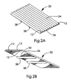
- FIG 2 is a perspective view of an alternative hernia repair plug of the present invention describing an embodiment wherein the hollow members 12 are in the form of a corrugated material 32 that is rolled up or otherwise bundled to form plug 14.
- the corrugated material 32 may be rolled up to create the plug 14 or simply folded and bundled by wrapping with a band 18 or my other means described previously.
- Plug 14 is affixed to sheet 16 as described previously.
- the resulting juncture of plug 14 and sheet 16 may be optionally reinforced by a fillet component 39.
- Fillet 39 is simply a disc of suitable material fitted around the base of plug 14 with enough interference to cause it to fit tightly around the base of plug 14.
- Fillet 39 may be joined to sheet 16 and plug 14 by various affixing methods described previously.
- sheet 16, fillet 39 and band 18 may be formed of a single piece.
- FIGs 2A and 2B show respectively upper and lower perspective views of a corrugated sheet material suitable for rolling or otherwise bundling to create plug 14.
- the corrugated sheet 32 comprises an upper layer 34 that is corrugated and affixed to a planar lower layer 36 by any suitable means.
- the corrugations result in a plurality of hollow members 12.
- Rolling of the corrugated sheet 32 to create plug component 14 is accomplished by rolling in a direction transverse to the length of the corrugations. As shown by Figure 2 , this results in the corrugations that provide the plurality of hollow members 12 extending along the length of the cylindrical plug 14, parallel to the longitudinal center line of the plug 14.
- the ends of the corrugations, opposite the end of the plug that is subsequently affixed to sheet 16, remain open.
- the corrugated sheet material 32 may be made from any desired bioabsorbable or non-bioabsorbable material. These corrugated sheets are anticipated to have other implantable applications in addition to use as the plug component of the hernia repair device described herein.
- the corrugated sheet material 32 may be useful in planar form for the repair of various tissue defects where a somewhat flexible, but "reinforced" sheet is desired. They may also have utility when rolled up to create a cylindrical shape appropriate for other applications.
- the hollow members resulting from the corrugated construction may be beneficial for various implantable applications.
- corrugated sheet material 32 may be provided with one or more transverse corrugations 38 on the lower surface of planar lower layer 36.
- these corrugations 38 become barbs or anchoring features extending circumferentially around the outer surface of plug 14, as will be further described.
- Corrugations 38 must be adequately flexible or distortable to allow the corrugated sheet 32 to be rolled up in the direction of their length. If desired, corrugations 38 may be cut transversely at intervals along their length to better enable the corrugated sheet 32 to be rolled up
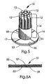
- Figure 3 shows a top view of plug 14 wherein the hollow members 12 have hexagonal transverse cross sections.
- Plug 14 may result from bundling a plurality of individual hollow members 12 or alternatively the members may be provided by extrusion of a honeycomb form wherein adjacent hollow members 12 share common walls. It is apparent that hollow members 12 may be provided in a variety of cross sectional shapes.
- Figure 4 shows a perspective view of a plug 14 provided with a band 18 that includes one or more barbs 42, intended to aid in the securement or anchoring of plug 14 within a tissue defect. Additionally, barbs 42 may serve as the band component 18 that holds hollow members 12 together in a bundle. These barb components 42 may be made in a variety of ways.
- Figure 4 shows two barbs made from discs of bioabsorbable material and provided with flanges 44 that enable the attachment of barbs 42 to the outer surface of plug 14. These anchoring barbs 42 may also be made by providing transverse corrugations 38 to corrugated sheet 32 prior to rolling corrugated sheet 32 to form plug 14, as described previously and shown in Figures 2A and 2B .
- the preferred bioabsorbable material for making the present invention is in the form of a web of continuous filaments which are made of at least one semi-crystalline polymeric component covalently bonded as a linear block copolymer with or blended with one or more semi-crystalline or amorphous polymeric components.
- the filaments are intermingled together to form a porous web of filaments, the filaments having multiple contact points with each other within the web.
- the filaments are bonded at the contact points without requisite for added adhesive binders, adjuncts or post extrusion melt processing.
- the web may be provided in forms with relatively high cohesive shear strength.
- the polymeric components of the filaments exist, at least temporarily, in a homogenous substantially phase miscible uncrystallized state.
- a self-cohering web has the ability of a melt formed structure, or component thereof, to effectively self-generate an attachment to itself without the requirement to undergo a melt, or undergo the requisite addition of supplementary adhesives, binders, or adhesive adjuncts either before or after structure formation.
- Figure 5 shows a perspective view of an alternative embodiment wherein sheet 16 is provided in two or more layers which may optionally be attached (e.g., laminated) together to create a composite sheet material 51 wherein the two layers have different properties.
- composite sheet material 51 includes a non-bioabsorbable layer 53 and a bioabsorbable layer 55.
- bioabsorbable layer 55 is placed in contact with the tissue adjacent the defect.
- the non-bioabsorbable layer 53 is preferably ePTFE and the bioabsorbable layer 55 is preferably a PGA:TMC material in the form of a self-cohering web as taught by the Hayes patents referred to above.
- Figure 5A shows a cross section of an alternative composite sheet material 51 wherein the non-bioabsorbable layer 53 has opposing surfaces 57 and 59 with different characteristics, for example, surface 57 being rougher and/or more open than surface 59.
- Rougher surface 57 is intended to encourage long term tissue attachment and ingrowth while smoother surface 59 is intended as a barrier to tissue attachment and ingrowth in order to prevent or reduce the likelihood of tissue adhesions.
- layer 53 is a porous material
- smoother surface 59 may be provided with a suitably small pore size while rougher surface 57 may be provided with a suitably larger pore size.
- sheet 16 may be the result of attaching two different layers together (as by bonding with an adhesive or melt bonding, or by mechanical fastening means such as sewing) to achieve the desired different surface characteristics.
- Rougher surface 57 is preferably provided with a covering or coating of bioabsorbable layer 55; when this layer 55 is bioabsorbed after a suitable time, rougher surface 57 remains to provide the desired long term tissue attachment.
- the presence of the bioabsorbable layer 55 is anticipated to enhance healing as a result of the increased inflammatory tissue response to the bioabsorbable material. This may be desirable due to the chemically inert character of the PTFE material (which consequently does little to elicit a biological reaction from adjacent tissue when implanted by itself).
- bioabsorbable layer 55 may be provided on one surface of an ePTFE material having similar opposing surfaces, as well as providing such a bioabsorbable layer on one surface of a differentially-sided ePTFE material.
- a preferred material for the non-bioabsorbable layer 53 is Gore-Tex Dual-MeshTM with CorduroyTM surface (Flagstaff AZ); this material has opposing surfaces with different tissue attachment and ingrowth characteristics as described above.
- Figure 5B shows a cross-section of a sheet material 16 of the present invention in the preferred form of a composite sheet material 52 wherein non-bioabsorbable material 60 is placed within bioabsorbable materials 62 and 63.
- Figure 5C shows a cross-section of a sheet material 16 of the present invention in the preferred form of a composite sheet material 52 wherein non-bioabsorbable material 60 is placed between bioabsorbable materials 62 and 63. Either of these composite sheet materials can serve as preferred base member components of the present invention.
- non-bioabsorbable material 60 is preferably a porous, expanded, polytetrafluoroethylene material (ePTFE). More preferably, the ePTFE material has one or more holes traversing the thickness of the material that are visible to the naked eye. The holes provide for ingrowth of tissue and additional flexibility of the composite sheet material. Most preferably, these "macroporous" ePTFE materials have holes arranged in a pattern that imparts additional flexibility to the composite sheet material while retaining sufficient mechanical strength to support damaged or injured tissue throughout the healing and rehabilitation process.
- ePTFE polytetrafluoroethylene material
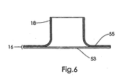
- Figure 6 is a longitudinal cross section of a band 18 that has been flared using suitable tooling to create the bioabsorbable layer 55 that may be adhered to a non-bioabsorbable layer 53 such as ePTFE. This describes an alternative way to accomplish the attachment of the plurality of hollow members to the sheet component.
- FIG. 1 This example describes the construction of a multiple tube hernia repair device of the present invention as shown in Figure 1 .
- a triblock copolymer of 67%/33% PGA:TMC (w/w) was acquired from US Surgical (Norwalk CT) and formed into a self-cohering web as generally taught by Hayes in U.S. Patent No. 6,165,217 . Sheets of this copolymer web material were formed into the 3 component types used in the construction of this device.
- a first component used for making this device was a tube formed from the self-cohering web sheets that had an area density of approximately 8-10 mg/cm 2 and a thickness of approximately 0.3mm.
- the first step in making a tube was to cut an approximately 25mm wide strip of the self-cohering web material from a piece of "unset” web sheet perpendicular to the belt direction used in forming the web. This strip of "unset” web material was then wrapped lengthwise around an approximately 5mm diameter stainless steel rod into a "cigarette roll” having an exposed edge at the surface of the resulting tube extending along the length of the tube. This material then self-cohered (as generally taught by Hayes in U.S.
- Patent 6,165,217 at the overlapping portion of the "cigarette roll” to form a 5mm diameter tube that was approximately 150mm long.
- the strip of "unset” web material wrapped around the stainless steel rod was then placed into a Baxter Scientific Products (McGaw Park IL) constant temperature oven, model DK-43, for approximately 30 minutes at 75°C to "set” the web.
- the stainless steel rod and "set” web material were then removed from the oven and allowed to cool. After cooling, the tube formed from the now “set” web material was slipped off of the stainless steel rod. Both ends of the "set” web tube were then trimmed leaving a tube that was approximately 90mm long.
- Each tube was then placed onto a cutting die to create the notches 24 shown in Figure 1B .
- a piece of 0.05mm thick Mylar® sheet (DuPont Company, Wilmington DE) was placed over the tube to protect it from contamination.
- a lightweight plastic-faced mallet was then used to lightly tap onto the tube through the Mylar® sheet to cut out two notches 24 and centering hole 26 with the cutting die. Multiple tubes were made using these methods.
- Another component used in making this device was a disc-shaped planar sheet of approximately 38mm in diameter.
- This disc-shaped planar sheet was made by first taking two 50 mm square sheets of the "unset" self-cohering web material, each with an area density of approximately 19 mg/cm 2 and approximately 1 mm thick. The two sheets were then stacked and placed in a restraining frame fitted about the perimeter of the stacked sheets. The restrained web material was then put into the Baxter Scientific Products constant temperature oven for approximately 30 minutes at 75°C to bond the two pieces together to create a thicker sheet and to "set” the web. After letting the web material cool to room temperature, a disc was cut using an approximately 38mm diameter circular cutting die punch.
- a third component used in making this device was a band formed from an approximately 19mm wide strip of copolymer web material.
- This copolymer web strip had an area density of approximately 6-8 mg/cm 2 and a thickness of approximately 0.3mm. This was made by rolling the strip of "unset" self-cohering web material into a tube and then holding the overlapped ends together to allow for self-cohering. The unset web material was then put into a Baxter Scientific Products constant temperature oven for approximately 30 minutes at 75°C. The resulting band was approximately 19mm in diameter.
- the device was then assembled by taking the disc first and centering it on a centering pin extending from the center of the surface of an assembly fixture. Then six of the tubes with notches and centering holes were placed on top of the disc, also centering them on the centering pin. The tubes were arranged so that they were equally spaced radially.
- the assembly was then placed onto a Branson model 8400 ultrasonic welder (Branson Sonic Power Co., Danbury CT).
- the ultrasonic welder had a Branson catenoidal hom, model 609-010-020 and an approximately 7.6mm diameter tip that had an approximately 3.2mm hole in the center to accommodate the centering pin of the assembly fixture.
- the ultrasonic welder also had a 1: 0.6 booster.
- the downstop was set at approximately 0.4mm with the downspeed set at number 4. Pressure was set at approximately 0.08 MPa with the trigger set at number 2; time was set to 0.2 seconds and the hold duration set at 1.0 seconds.
- the ultrasonic welder was shut and activated 3 times for each device. After ultrasonic welding, the six tubes were securely attached to the disc-shaped sheet. The tubes were then folded up so that they were oriented to be substantially perpendicular to the sheet component. The band component was then placed around the tubes to hold them in a bundled configuration wherein the tubes were substantially parallel to each other along their lengths. Four slits, spaced equally apart, were then cut into the disc approximately three quarters of the way from the perimeter of the disc to the center to facilitate insertion on the device into a hernia defect site.
- FIG. 4 This example describes the construction of a corrugated tube hernia repair device of the present invention as shown in Figure 4 .
- a triblock copolymer of 50% PGA:TMC (w/w) was made and formed into a self-cohering web as generally taught by Hayes in U.S. Patent 6,165,217 . Sheets of this copolymer web material were formed into some of the components used in the construction of this device. Other components were made from expanded polytetrafluoroethylene (ePTFE) and from a bioabsorbable polymer adhesive, as described below.
- ePTFE expanded polytetrafluoroethylene
- a corrugated sheet was made by first placing a piece of the "unset" PGA:TMC web sheet (approximately 100mm square, about 0.2mm thick having and having an area density of approximately 4-6 gm/cm 2 ) onto a piece of PeCap® polyester screen, product number 7-1000/45 (Sefar America, Monterey Park CA) material. This screen material, by virtue of its surface texture, was used to restrain the web material from dimensional change during the "setting” process.
- a fixture approximately 125 mm square was then placed onto the surface of the web sheet. The fixture was provided with a set of multiple parallel rods with all of their centerlines in the same plane, the rods being of approximately 2.4mm diameter and spaced 5.3mm center-to-center. These rods acted as mandrels for forming the hollow members of the corrugation.
- a second piece of "unset" web material of the same type as the first and of approximately the same dimensions was then placed on top of the multiple parallel rod fixture. Unsecured rods of approximately the same diameter as the rods in the fixture were then placed on top of the second piece of "unset” web material, between the parallel rods of the underlying fixture. These unsecured rods were individually pushed down until they were in the same plane as the parallel rods of the underlying fixture. The result was that the second piece of "unset” web material now formed the hollow members of the corrugated sheet as it assumed a convoluted shape with self-cohering contact points on the bottom piece of "unset” web material.
- PeCap® polyester screen was placed on top of the upper piece of "unset” web material to restrain it from dimensional changes during the "setting” process.
- An aluminum plate was placed on top of the polyester and then a weight was placed on top of the entire assembly. The assembly was then placed into an oven at 80°C for 30 minutes to "set” the web material. After “setting” in the oven, the web material was allowed to cool and then removed from the fixture of multiple parallel rods.
- Another component used in making this device was a sheet component with a fillet and band for accepting a rolled up piece of corrugated web material.
- the first step in making this sheet component was to provide a piece of "unset” web sheet material approximately 50mm square.
- a circular cutting die was used to cut an approximately 13mm diameter hole in the center of it.
- a 19mm diameter aluminum rod, approximately 150mm long, was then fixtured to stand perpendicularly on a flat aluminum plate.
- the piece of "unset” web material with a hole in its center was then pushed over the aluminum rod.
- the hole in the "unset” web was smaller than the diameter of the aluminum rod, and because the "unset” web material was deformable, the difference in diameters between the hole in the web material and the aluminum rod produced a flared hole in the "unset” web.
- the aluminum rod and web material were then placed into an oven at 80°C for 30 minutes to "set” the web material. After allowing the web material to cool, it was removed from the aluminum rod.
- the flared hole in the "set” web material formed a combined fillet and band (as in Figure 6 ) for accepting the corrugated web material.
- the piece of "set” web material with the flange was then adhered to a piece of ePTFE material by using a bioabsorbable adhesive.
- the adhesive was made from a mixture of poly(85% d,l-lactide-co-15% glycolide) (by mole; abbreviated as 85% d,l-PLA:15% PGA) mixed 1:4 by weight in acetone. It is apparent that this device could be made without the ePTFE layer.
- Barb components ( Figure 4 , reference no. 42) were individually formed by taking a piece of "unset” PGA:TMC web material approximately 65mm long x 13mm wide and wrapping this lengthwise around a suitably tapered mandrel chosen to shape the downwardly-angled barb.
- the strip of "unset” web material was temporarily restrained to the mandrel by using a piece of PTFE pipe tape.
- the tapered mandrel and restrained "unset” web material were then put into an oven at approximately 80°C for approximately 30 minutes to "set the web material. After the web material was “set” in the oven, it was removed from the mandrel. Cutouts were then made to the center region of the now tapered band to create flanges 44.
- the device was then assembled by taking the corrugated sheet and rolling it into a tube. Some of the bioabsorbable adhesive was applied to the circumference of one end of this tube and also to the walls of the filleted band portion to be attached to the sheet component. The end of the tube with adhesive on it was then inserted in a perpendicular orientation into the filleted band portion of the sheet component. Bioabsorbable adhesive was then applied to the interiors of a pair of anchoring barbs, after which they were immediately fitted over the circumference of the plug component.
- This example describes a method used to alter the stiffness and rate of bioabsorption of a bioabsorbable device.
- a solution was made by mixing 65% d,l-PLA:35% PGA available from Birmingham Polymers (Birmingham AL) in a 1:10 ratio by weight with acetone.
- a device as described in Example 1 was dipped into this solution which imbibed into the structure of the device, and then allowed to air dry. The resulting coated device was stiffer than prior to imbibing. Alternatively, this solution could be sprayed onto devices to achieve similar effects.
- Other copolymer ratios can also be used to vary the stiffness and rate of bioabsorption.
- other ratios of polymer:acetone can be used to vary the final amount of polymer imbibed into or sprayed onto the structure of the device.
- This example describes construction of a preferred embodiment of the present invention having a base member in the form of a composite sheet material having a non-bioabsorbable component placed within a bioabsorbable component.
- This composite base member can be used with any of the embodiments described herein.
- the composite sheet material for use as the base member of the present invention was made in the form of a laminate of a non-bioabsorbable ePTFE material and a bioasborbable PGA:TMC self-cohering web material (67:33 weight percent) as taught by Hayes ( Ibid .).
- the ePTFE material made according to U.S. Patent No. 5,858,505 was obtained from W.L. Gore & Associates, Inc., Flagstaff, AZ under the tradename GORE MYCROMESH® Biomaterial.
- the material has holes traversing the thickness of the material visible to the naked eye.
- the starting materials for the bioabsorbable PGA:TMC component were obtained as described above in Example 1.
- the composite material was constructed by centering a circular 7cm diameter piece of ePTFE material between two 10cm X 10cm sheets of PGA:TMC material.
- the PGA:TMC material was in the form of an unset web having an area density between 20mg/cm 2 and 25mg/cm 2 .
- the composite was overlaid on both sides with a woven polyester web material (SEFAR AMERICA, INC, SEFAR product number 7-1000/45 PeCap® polyester endless belt) and placed in a restraining apparatus. Approximately five (5) pounds of force was applied to the polyester web pieces with the apparatus.
- the restrained combination was placed in a constant temperature oven at 100°C for ten (10) minutes in order to set the bioabsorbable PGA:TMC web material and enclose the non-bioabsorbable ePTFE material within the bioabsorbable material.
- the composite material was allowed to cool to room temperature before being removed from the restraining apparatus.
- Example 1 Excess bioabsorbable material was trimmed from the composite sheet material to form a base member of the present invention.
- the base member was attached to a plurality of substantially hollow members as described in Example 1.
- This example describes construction of a preferred embodiment of the present invention having a base member in the form of a composite sheet material having a non-bioabsorbable component placed between layers of bioabsorbable material.
- the bioabsorbable self-cohering web had a volume percent of 67:33, an area density of approximately 50 mg/cm 2 , and a volume density of 0.35 g/cc.
- the ePTFE material was obtained from W.L. Gore & Associates, Inc., Flagstaff, AZ under the tradename GORE DUALMESH® Biomaterial.
- the ePTFE material is in the form of a sheet having different textures on opposite sides of the sheet material to elicit different tissue responses at an implantation site.
- non-bioabsorbable ePTFE material was placed between two layers of bioabsorbable PGA:TMC material, restrained as described in Example 4, and ultrasonically welded together.
- the ultrasonic welder had a Branson circular high gain horn, model 318 004145 with an approximately 5cm diameter tip having a machined face honeycomb hole pattern. Each 6mm hexagon machined hole in the honeycomb pattern was spaced at 1 mm.
- the ultrasonic welder also had a 1: 2.5 booster.
- the downspeed was set at number 4.
- Applied pressure was set at approximately 0.65 MPa with the trigger set at number 2.
- the welding time was 0.8 seconds and assembly held in place for a duration of 2.5 seconds.
- Example 1 Excess bioabsorbable material was trimmed from the composite sheet material to form a base member of the present invention.
- the base member was attached to a plurality of substantially hollow members as described in Example 1.
Claims (3)
- Dispositif implantable de réparation d'une hernie (10) comprenant:une pluralité d'éléments substantiellement creux (12);dans lequel chaque élément substantiellement creux (12) comporte deux extrémités, au moins une desdites extrémités étant ouverte;dans lequel chaque élément substantiellement creux (12) est fait d'un matériau polymère bio-absorbable sous forme d'un tissu auto-adhérant; etdans lequel ladite pluralité d'éléments substantiellement creux (12) est reliée à un élément de base substantiellement plan sous la forme d'un composite (52) fait d'un matériau polymère non bio-absorbable (60) placé entre au moins deux couches (62, 63) d'un matériau polymère bio-absorbable sous la forme d'un tissu auto-adhérant.
- Dispositif implantable de réparation d'une hernie (10) selon la revendication 1, dans lequel ledit tissu auto-adhérant est produit à partir d'un copolymère d'acide polyglycolique et de carbonate de triméthylène (PGA:TMC).
- Dispositif implantable de réparation d'une hernie (10) selon la revendication 1, dans lequel ledit matériau polymère non bio-absorbable est le polytétrafluoroéthylène expansé (ePTFE).
Applications Claiming Priority (2)
| Application Number | Priority Date | Filing Date | Title |
|---|---|---|---|
| US11/015,147 US7776101B2 (en) | 2003-06-18 | 2004-12-17 | Soft tissue defect repair device |
| PCT/US2005/045943 WO2006086076A2 (fr) | 2004-12-17 | 2005-12-15 | Dispositif destine a la reparation de defauts dans les tissus mous |
Publications (3)
| Publication Number | Publication Date |
|---|---|
| EP1845865A2 EP1845865A2 (fr) | 2007-10-24 |
| EP1845865A4 EP1845865A4 (fr) | 2010-02-10 |
| EP1845865B1 true EP1845865B1 (fr) | 2010-12-15 |
Family
ID=36793539
Family Applications (1)
| Application Number | Title | Priority Date | Filing Date |
|---|---|---|---|
| EP05854620A Active EP1845865B1 (fr) | 2004-12-17 | 2005-12-15 | Dispositif destine a la reparation de defauts dans les tissus mous |
Country Status (6)
| Country | Link |
|---|---|
| US (1) | US7776101B2 (fr) |
| EP (1) | EP1845865B1 (fr) |
| AT (1) | ATE491407T1 (fr) |
| CA (1) | CA2599155C (fr) |
| DE (1) | DE602005025411D1 (fr) |
| WO (1) | WO2006086076A2 (fr) |
Families Citing this family (21)
| Publication number | Priority date | Publication date | Assignee | Title |
|---|---|---|---|---|
| US6991637B2 (en) * | 2003-06-18 | 2006-01-31 | Gore Enterprise Holdings, Inc. | Soft tissue defect repair device |
| US20120010726A1 (en) * | 2003-09-10 | 2012-01-12 | Lukas Bluecher | Adhesion-Resistant Surgical Access, Reinforcement and Closure Prosthetic |
| US7789888B2 (en) * | 2005-02-14 | 2010-09-07 | Bartee Chad M | PTFE composite multi-layer material |
| US20070026039A1 (en) * | 2005-07-29 | 2007-02-01 | Drumheller Paul D | Composite self-cohered web materials |
| AU2012202897B2 (en) * | 2005-07-29 | 2013-12-05 | W. L. Gore & Associates, Inc. | Composite self-cohered web materials |
| US20070026040A1 (en) * | 2005-07-29 | 2007-02-01 | Crawley Jerald M | Composite self-cohered web materials |
| US7655584B2 (en) * | 2005-07-29 | 2010-02-02 | Gore Enterprise Holdings, Inc. | Highly porous self-cohered web materials |
| US7604668B2 (en) * | 2005-07-29 | 2009-10-20 | Gore Enterprise Holdings, Inc. | Composite self-cohered web materials |
| US7850810B2 (en) * | 2005-07-29 | 2010-12-14 | Gore Enterprise Holdings, Inc. | Method of making porous self-cohered web materials |
| US20070155010A1 (en) * | 2005-07-29 | 2007-07-05 | Farnsworth Ted R | Highly porous self-cohered fibrous tissue engineering scaffold |
| US7655288B2 (en) * | 2005-07-29 | 2010-02-02 | Gore Enterprise Holdings, Inc. | Composite self-cohered web materials |
| US8048503B2 (en) * | 2005-07-29 | 2011-11-01 | Gore Enterprise Holdings, Inc. | Highly porous self-cohered web materials |
| US20070027551A1 (en) * | 2005-07-29 | 2007-02-01 | Farnsworth Ted R | Composite self-cohered web materials |
| US20090192530A1 (en) * | 2008-01-29 | 2009-07-30 | Insightra Medical, Inc. | Fortified mesh for tissue repair |
| DE102007037053A1 (de) * | 2007-07-24 | 2009-01-29 | Aesculap Ag | Hämostyptikum für die minimal-invasive Operation |
| US20090187197A1 (en) * | 2007-08-03 | 2009-07-23 | Roeber Peter J | Knit PTFE Articles and Mesh |
| US20090036996A1 (en) * | 2007-08-03 | 2009-02-05 | Roeber Peter J | Knit PTFE Articles and Mesh |
| US8551125B2 (en) * | 2011-06-06 | 2013-10-08 | C. R. Bard, Inc. | Implantable mesh prostheses and method of manufacturing same |
| EP2543339A1 (fr) * | 2011-07-05 | 2013-01-09 | Aesculap AG | Implant chirurgical, en particulier pour une utilisation en tant qu'implant de réparation d'hernies |
| US10588732B2 (en) | 2014-03-07 | 2020-03-17 | IconLab USA, Inc. | Multipurpose implant with modeled surface structure for soft tissue reconstruction |
| RU2699811C1 (ru) | 2014-03-07 | 2019-09-11 | Айконлаб Инк. | Многоцелевой имплантат с заданной структурой поверхности для реконструкции мягких тканей |
Family Cites Families (32)
| Publication number | Priority date | Publication date | Assignee | Title |
|---|---|---|---|---|
| US4769038A (en) | 1986-03-18 | 1988-09-06 | C. R. Bard, Inc. | Prostheses and techniques and repair of inguinal and femoral hernias |
| US4854316A (en) | 1986-10-03 | 1989-08-08 | Davis Emsley A | Apparatus and method for repairing and preventing para-stomal hernias |
| US5425766A (en) * | 1987-03-09 | 1995-06-20 | Astra Tech Aktiebolag | Resorbable prosthesis |
| US4891263A (en) * | 1987-12-17 | 1990-01-02 | Allied-Signal Inc. | Polycarbonate random copolymer-based fiber compositions and method of melt-spinning same and device |
| US5092884A (en) * | 1988-03-24 | 1992-03-03 | American Cyanamid Company | Surgical composite structure having absorbable and nonabsorbable components |
| GB2222954B (en) | 1988-08-31 | 1991-11-13 | Ethicon Inc | Tubular implant and process for the production thereof |
| US4990158A (en) | 1989-05-10 | 1991-02-05 | United States Surgical Corporation | Synthetic semiabsorbable tubular prosthesis |
| US5098779A (en) | 1990-06-25 | 1992-03-24 | W. L. Gore & Associates, Inc. | Carvable implant material |
| US5116357A (en) * | 1990-10-11 | 1992-05-26 | Eberbach Mark A | Hernia plug and introducer apparatus |
| US5254133A (en) | 1991-04-24 | 1993-10-19 | Seid Arnold S | Surgical implantation device and related method of use |
| US5462781A (en) * | 1991-06-14 | 1995-10-31 | W. L. Gore & Associates, Inc. | Surface modified porous expanded polytetrafluoroethylene and process for making |
| US5258000A (en) | 1991-11-25 | 1993-11-02 | Cook Incorporated | Tissue aperture repair device |
| US5147374A (en) * | 1991-12-05 | 1992-09-15 | Alfredo Fernandez | Prosthetic mesh patch for hernia repair |
| WO1993017635A1 (fr) | 1992-03-04 | 1993-09-16 | C.R. Bard, Inc. | Prothese composite et procede de limitation de la frequence d'adhesions post-operatoires |
| WO1993021858A1 (fr) | 1992-04-24 | 1993-11-11 | Osteotech, Inc. | Dispositifs servant a empecher l'adherence de tissus |
| US5356432B1 (en) | 1993-02-05 | 1997-02-04 | Bard Inc C R | Implantable mesh prosthesis and method for repairing muscle or tissue wall defects |
| EP0726841B1 (fr) | 1993-02-18 | 2000-03-01 | W.L. Gore & Associates, Inc. | Materiaux en polytetrafluoroethylene poreux a perforations macroscopiques |
| US5709713A (en) * | 1995-03-31 | 1998-01-20 | Cardiovascular Concepts, Inc. | Radially expansible vascular prosthesis having reversible and other locking structures |
| US5716408A (en) | 1996-05-31 | 1998-02-10 | C.R. Bard, Inc. | Prosthesis for hernia repair and soft tissue reconstruction |
| US6120539A (en) | 1997-05-01 | 2000-09-19 | C. R. Bard Inc. | Prosthetic repair fabric |
| US6241768B1 (en) | 1997-08-27 | 2001-06-05 | Ethicon, Inc. | Prosthetic device for the repair of a hernia |
| FR2767672B1 (fr) * | 1997-08-27 | 1999-11-26 | Ethnor | Protheses pour l'obturation de canaux herniaires |
| FR2767671B1 (fr) | 1997-08-27 | 1999-11-26 | Ethnor | Dispositif obturateur prothetique pour l'obturation de canaux herniaires |
| US6165217A (en) * | 1997-10-02 | 2000-12-26 | Gore Enterprise Holdings, Inc. | Self-cohering, continuous filament non-woven webs |
| WO1999021507A2 (fr) * | 1997-10-28 | 1999-05-06 | Hills, Inc. | Fibres synthetiques a usage medical et leur procede de fabrication |
| US6166286A (en) | 1998-09-16 | 2000-12-26 | Arcilius Consultadoria E Servicos Lda | Mesh plug kit for the inguinal box surgical technique for hernioplasty |
| US20030225355A1 (en) * | 1998-10-01 | 2003-12-04 | Butler Charles E. | Composite material for wound repair |
| US6241763B1 (en) * | 1999-06-08 | 2001-06-05 | William J. Drasler | In situ venous valve device and method of formation |
| US6425924B1 (en) | 2000-03-31 | 2002-07-30 | Ethicon, Inc. | Hernia repair prosthesis |
| US6755868B2 (en) | 2002-03-22 | 2004-06-29 | Ethicon, Inc. | Hernia repair device |
| EP1545390A4 (fr) | 2002-08-23 | 2007-05-09 | Proxy Biomedical Ltd | Implant tridimensionnel |
| US6991637B2 (en) | 2003-06-18 | 2006-01-31 | Gore Enterprise Holdings, Inc. | Soft tissue defect repair device |
-
2004
- 2004-12-17 US US11/015,147 patent/US7776101B2/en active Active
-
2005
- 2005-12-15 CA CA2599155A patent/CA2599155C/fr active Active
- 2005-12-15 WO PCT/US2005/045943 patent/WO2006086076A2/fr active Application Filing
- 2005-12-15 DE DE602005025411T patent/DE602005025411D1/de active Active
- 2005-12-15 EP EP05854620A patent/EP1845865B1/fr active Active
- 2005-12-15 AT AT05854620T patent/ATE491407T1/de not_active IP Right Cessation
Also Published As
| Publication number | Publication date |
|---|---|
| WO2006086076A3 (fr) | 2007-02-01 |
| ATE491407T1 (de) | 2011-01-15 |
| EP1845865A2 (fr) | 2007-10-24 |
| DE602005025411D1 (de) | 2011-01-27 |
| US20050165447A1 (en) | 2005-07-28 |
| EP1845865A4 (fr) | 2010-02-10 |
| CA2599155C (fr) | 2010-08-10 |
| US7776101B2 (en) | 2010-08-17 |
| WO2006086076A2 (fr) | 2006-08-17 |
| CA2599155A1 (fr) | 2006-08-17 |
Similar Documents
| Publication | Publication Date | Title |
|---|---|---|
| EP1845865B1 (fr) | Dispositif destine a la reparation de defauts dans les tissus mous | |
| EP1633278B1 (fr) | Dispositif de reparation de defauts de tissus mous | |
| US8623034B2 (en) | Soft tissue repair implant | |
| US9788930B2 (en) | Soft tissue implants and methods for making same | |
| US9750594B2 (en) | Soft tissue implants and methods for making same | |
| KR102066230B1 (ko) | 개선된 봉합물 | |
| CA2616886C (fr) | Materiaux en bande hautement poreux a auto-cohesion possedant des proprietes hemostatiques | |
| US7659219B2 (en) | Highly porous self-cohered web materials having haemostatic properties | |
| JP5592231B2 (ja) | 生体吸収性支持部材を備えた組織修復器具 | |
| CA2828153A1 (fr) | Substrat poreux dote de pointes ferromagnetiques | |
| CN111432749A (zh) | 自抓握式疝假体 | |
| CA3038198A1 (fr) | Fixation indirecte d'une aiguille a une suture par maille |
Legal Events
| Date | Code | Title | Description |
|---|---|---|---|
| PUAI | Public reference made under article 153(3) epc to a published international application that has entered the european phase |
Free format text: ORIGINAL CODE: 0009012 |
|
| 17P | Request for examination filed |
Effective date: 20070904 |
|
| AK | Designated contracting states |
Kind code of ref document: A2 Designated state(s): AT BE BG CH CY CZ DE DK EE ES FI FR GB GR HU IE IS IT LI LT LU LV MC NL PL PT RO SE SI SK TR |
|
| DAX | Request for extension of the european patent (deleted) | ||
| A4 | Supplementary search report drawn up and despatched |
Effective date: 20100112 |
|
| RIC1 | Information provided on ipc code assigned before grant |
Ipc: A61F 2/00 20060101AFI20100105BHEP |
|
| GRAP | Despatch of communication of intention to grant a patent |
Free format text: ORIGINAL CODE: EPIDOSNIGR1 |
|
| RIC1 | Information provided on ipc code assigned before grant |
Ipc: A61F 2/00 20060101AFI20100629BHEP |
|
| GRAS | Grant fee paid |
Free format text: ORIGINAL CODE: EPIDOSNIGR3 |
|
| GRAA | (expected) grant |
Free format text: ORIGINAL CODE: 0009210 |
|
| AK | Designated contracting states |
Kind code of ref document: B1 Designated state(s): AT BE BG CH CY CZ DE DK EE ES FI FR GB GR HU IE IS IT LI LT LU LV MC NL PL PT RO SE SI SK TR |
|
| REG | Reference to a national code |
Ref country code: GB Ref legal event code: FG4D Ref country code: CH Ref legal event code: EP |
|
| REG | Reference to a national code |
Ref country code: IE Ref legal event code: FG4D |
|
| REF | Corresponds to: |
Ref document number: 602005025411 Country of ref document: DE Date of ref document: 20110127 Kind code of ref document: P |
|
| REG | Reference to a national code |
Ref country code: NL Ref legal event code: T3 |
|
| REG | Reference to a national code |
Ref country code: SE Ref legal event code: TRGR |
|
| PG25 | Lapsed in a contracting state [announced via postgrant information from national office to epo] |
Ref country code: LT Free format text: LAPSE BECAUSE OF FAILURE TO SUBMIT A TRANSLATION OF THE DESCRIPTION OR TO PAY THE FEE WITHIN THE PRESCRIBED TIME-LIMIT Effective date: 20101215 |
|
| LTIE | Lt: invalidation of european patent or patent extension |
Effective date: 20101215 |
|
| PG25 | Lapsed in a contracting state [announced via postgrant information from national office to epo] |
Ref country code: SI Free format text: LAPSE BECAUSE OF FAILURE TO SUBMIT A TRANSLATION OF THE DESCRIPTION OR TO PAY THE FEE WITHIN THE PRESCRIBED TIME-LIMIT Effective date: 20101215 Ref country code: CY Free format text: LAPSE BECAUSE OF FAILURE TO SUBMIT A TRANSLATION OF THE DESCRIPTION OR TO PAY THE FEE WITHIN THE PRESCRIBED TIME-LIMIT Effective date: 20101215 Ref country code: LV Free format text: LAPSE BECAUSE OF FAILURE TO SUBMIT A TRANSLATION OF THE DESCRIPTION OR TO PAY THE FEE WITHIN THE PRESCRIBED TIME-LIMIT Effective date: 20101215 Ref country code: BG Free format text: LAPSE BECAUSE OF FAILURE TO SUBMIT A TRANSLATION OF THE DESCRIPTION OR TO PAY THE FEE WITHIN THE PRESCRIBED TIME-LIMIT Effective date: 20110315 Ref country code: FI Free format text: LAPSE BECAUSE OF FAILURE TO SUBMIT A TRANSLATION OF THE DESCRIPTION OR TO PAY THE FEE WITHIN THE PRESCRIBED TIME-LIMIT Effective date: 20101215 Ref country code: AT Free format text: LAPSE BECAUSE OF FAILURE TO SUBMIT A TRANSLATION OF THE DESCRIPTION OR TO PAY THE FEE WITHIN THE PRESCRIBED TIME-LIMIT Effective date: 20101215 |
|
| PG25 | Lapsed in a contracting state [announced via postgrant information from national office to epo] |
Ref country code: CZ Free format text: LAPSE BECAUSE OF FAILURE TO SUBMIT A TRANSLATION OF THE DESCRIPTION OR TO PAY THE FEE WITHIN THE PRESCRIBED TIME-LIMIT Effective date: 20101215 Ref country code: MC Free format text: LAPSE BECAUSE OF NON-PAYMENT OF DUE FEES Effective date: 20101231 Ref country code: EE Free format text: LAPSE BECAUSE OF FAILURE TO SUBMIT A TRANSLATION OF THE DESCRIPTION OR TO PAY THE FEE WITHIN THE PRESCRIBED TIME-LIMIT Effective date: 20101215 Ref country code: PT Free format text: LAPSE BECAUSE OF FAILURE TO SUBMIT A TRANSLATION OF THE DESCRIPTION OR TO PAY THE FEE WITHIN THE PRESCRIBED TIME-LIMIT Effective date: 20110415 Ref country code: GR Free format text: LAPSE BECAUSE OF FAILURE TO SUBMIT A TRANSLATION OF THE DESCRIPTION OR TO PAY THE FEE WITHIN THE PRESCRIBED TIME-LIMIT Effective date: 20110316 Ref country code: ES Free format text: LAPSE BECAUSE OF FAILURE TO SUBMIT A TRANSLATION OF THE DESCRIPTION OR TO PAY THE FEE WITHIN THE PRESCRIBED TIME-LIMIT Effective date: 20110326 Ref country code: IS Free format text: LAPSE BECAUSE OF FAILURE TO SUBMIT A TRANSLATION OF THE DESCRIPTION OR TO PAY THE FEE WITHIN THE PRESCRIBED TIME-LIMIT Effective date: 20110415 |
|
| REG | Reference to a national code |
Ref country code: CH Ref legal event code: PL |
|
| PG25 | Lapsed in a contracting state [announced via postgrant information from national office to epo] |
Ref country code: SK Free format text: LAPSE BECAUSE OF FAILURE TO SUBMIT A TRANSLATION OF THE DESCRIPTION OR TO PAY THE FEE WITHIN THE PRESCRIBED TIME-LIMIT Effective date: 20101215 Ref country code: PL Free format text: LAPSE BECAUSE OF FAILURE TO SUBMIT A TRANSLATION OF THE DESCRIPTION OR TO PAY THE FEE WITHIN THE PRESCRIBED TIME-LIMIT Effective date: 20101215 Ref country code: RO Free format text: LAPSE BECAUSE OF FAILURE TO SUBMIT A TRANSLATION OF THE DESCRIPTION OR TO PAY THE FEE WITHIN THE PRESCRIBED TIME-LIMIT Effective date: 20101215 |
|
| PLBE | No opposition filed within time limit |
Free format text: ORIGINAL CODE: 0009261 |
|
| STAA | Information on the status of an ep patent application or granted ep patent |
Free format text: STATUS: NO OPPOSITION FILED WITHIN TIME LIMIT |
|
| PG25 | Lapsed in a contracting state [announced via postgrant information from national office to epo] |
Ref country code: LI Free format text: LAPSE BECAUSE OF NON-PAYMENT OF DUE FEES Effective date: 20101231 Ref country code: DK Free format text: LAPSE BECAUSE OF FAILURE TO SUBMIT A TRANSLATION OF THE DESCRIPTION OR TO PAY THE FEE WITHIN THE PRESCRIBED TIME-LIMIT Effective date: 20101215 Ref country code: CH Free format text: LAPSE BECAUSE OF NON-PAYMENT OF DUE FEES Effective date: 20101231 |
|
| 26N | No opposition filed |
Effective date: 20110916 |
|
| REG | Reference to a national code |
Ref country code: DE Ref legal event code: R097 Ref document number: 602005025411 Country of ref document: DE Effective date: 20110916 |
|
| PG25 | Lapsed in a contracting state [announced via postgrant information from national office to epo] |
Ref country code: HU Free format text: LAPSE BECAUSE OF FAILURE TO SUBMIT A TRANSLATION OF THE DESCRIPTION OR TO PAY THE FEE WITHIN THE PRESCRIBED TIME-LIMIT Effective date: 20110616 Ref country code: LU Free format text: LAPSE BECAUSE OF NON-PAYMENT OF DUE FEES Effective date: 20101215 |
|
| PG25 | Lapsed in a contracting state [announced via postgrant information from national office to epo] |
Ref country code: TR Free format text: LAPSE BECAUSE OF FAILURE TO SUBMIT A TRANSLATION OF THE DESCRIPTION OR TO PAY THE FEE WITHIN THE PRESCRIBED TIME-LIMIT Effective date: 20101215 |
|
| REG | Reference to a national code |
Ref country code: GB Ref legal event code: 732E Free format text: REGISTERED BETWEEN 20150723 AND 20150729 |
|
| REG | Reference to a national code |
Ref country code: DE Ref legal event code: R082 Ref document number: 602005025411 Country of ref document: DE Representative=s name: MARKS & CLERK (LUXEMBOURG) LLP, LU Ref country code: DE Ref legal event code: R081 Ref document number: 602005025411 Country of ref document: DE Owner name: W.L. GORE & ASSOCIATES, INC., NEWARK, US Free format text: FORMER OWNER: GORE ENTERPRISE HOLDINGS, INC., NEWARK, DEL., US |
|
| REG | Reference to a national code |
Ref country code: FR Ref legal event code: PLFP Year of fee payment: 11 |
|
| REG | Reference to a national code |
Ref country code: FR Ref legal event code: TP Owner name: W.L. GORE & ASSOCIATES, INC., US Effective date: 20160510 |
|
| REG | Reference to a national code |
Ref country code: FR Ref legal event code: PLFP Year of fee payment: 12 |
|
| REG | Reference to a national code |
Ref country code: FR Ref legal event code: PLFP Year of fee payment: 13 |
|
| PGFP | Annual fee paid to national office [announced via postgrant information from national office to epo] |
Ref country code: IT Payment date: 20221122 Year of fee payment: 18 |
|
| PGFP | Annual fee paid to national office [announced via postgrant information from national office to epo] |
Ref country code: BE Payment date: 20221122 Year of fee payment: 18 |
|
| PGFP | Annual fee paid to national office [announced via postgrant information from national office to epo] |
Ref country code: NL Payment date: 20231121 Year of fee payment: 19 |
|
| PGFP | Annual fee paid to national office [announced via postgrant information from national office to epo] |
Ref country code: GB Payment date: 20231121 Year of fee payment: 19 |
|
| PGFP | Annual fee paid to national office [announced via postgrant information from national office to epo] |
Ref country code: SE Payment date: 20231121 Year of fee payment: 19 Ref country code: IE Payment date: 20231123 Year of fee payment: 19 Ref country code: FR Payment date: 20231122 Year of fee payment: 19 Ref country code: DE Payment date: 20231121 Year of fee payment: 19 |
|
| PGFP | Annual fee paid to national office [announced via postgrant information from national office to epo] |
Ref country code: BE Payment date: 20231121 Year of fee payment: 19 |