EP1845189B1 - Method for controlling temperature of ceramic elements of a support or peel guide rail in a paper producing system and device and support or peel guide rail for carrying out this method - Google Patents
Method for controlling temperature of ceramic elements of a support or peel guide rail in a paper producing system and device and support or peel guide rail for carrying out this method Download PDFInfo
- Publication number
- EP1845189B1 EP1845189B1 EP06450181A EP06450181A EP1845189B1 EP 1845189 B1 EP1845189 B1 EP 1845189B1 EP 06450181 A EP06450181 A EP 06450181A EP 06450181 A EP06450181 A EP 06450181A EP 1845189 B1 EP1845189 B1 EP 1845189B1
- Authority
- EP
- European Patent Office
- Prior art keywords
- supporting
- scraper bar
- carrier medium
- channel
- temperature
- Prior art date
- Legal status (The legal status is an assumption and is not a legal conclusion. Google has not performed a legal analysis and makes no representation as to the accuracy of the status listed.)
- Not-in-force
Links
Images


Classifications
-
- D—TEXTILES; PAPER
- D21—PAPER-MAKING; PRODUCTION OF CELLULOSE
- D21F—PAPER-MAKING MACHINES; METHODS OF PRODUCING PAPER THEREON
- D21F1/00—Wet end of machines for making continuous webs of paper
- D21F1/48—Suction apparatus
- D21F1/483—Drainage foils and bars
Definitions
- the subject invention relates to a method for controlling the temperature of the ceramic elements of a support or squeegee, which is assigned in a plant for paper production to the located therein at least one screen belt or at least one felt belt. Furthermore, the invention relates to a device and a support or squeegee for performing this method.
- Equipment for paper production have at least one screen belt and further at least one felt belt, which are assigned to the two bands in their direction of succession, aligned transversely to the bands supporting strips over which the screen belt and the felt belt are guided.
- the support strips In a first area of the paper-making plant, the support strips also serve as squeegee strips for the liquids emerging from the paper pulp and passing through the sieve belt. Since these Abstützorgn are exposed to large mechanical and corrosive loads, there is a need to provide these on their the Siebb Sn or the felt tapes facing surfaces with plates of a ceramic material to which the screen belt or the felt belt to the plant.
- the screen belt or the felt belt at very high speeds of e.g. Moved 40 m / sec over the Abstützorgn away.
- the support strips means for sucking the emerging from the pulp liquids or for sucking air to dry the paper belt resting on the wire belt or for drying the felt belt, whereby the wire belt or the felt on the support bars with very high pressure rest. As a result, frictional forces occur, by which the ceramic elements can be heated strongly.
- the support strips cool down to the ambient temperature.
- the paper pulp is sprayed onto the sieve belt, which can have a temperature of up to 90 °.
- a steam hood can be provided, within which superheated steam is located, which serves to dry the paper tape and through which the ceramic elements can be subjected to temperatures up to 150 ° C. It should also be noted that the ceramic elements of the support or squeegee have a very low thermal conductivity.
- the ceramic elements of the supporting or wiper strips are subject to very high thermal stresses, which can change within a very short time within a range of about 200 ° C.
- This control of the operation of the system is characterized in that the support or wiper blades are assigned spray nozzles through which water is sprayed onto the support or squeegee, and that the trained with Abstütz- or squeegee suction boxes are provided with vacuum lines through which of the pressure with which the screen belts abut against the support or wiper strips, can be controlled.
- the subject invention is therefore based on the object to provide a method by which the individual located in a plant for paper production support or squeegee can be protected from being damaged due to occurring in these thermal stresses.
- this will According to the invention achieved in that the support or squeegee is formed with at least one channel through which a carrier medium for heat or for cold is passed.
- a mixing valve is provided in the line leading to the at least one channel, are connected to which lines for carrier media for heat or for cold and which is set to the temperature which should have the respective support or squeegee ,
- a temperature sensor may be provided in the leading away from the support or squeegee line, by which the temperature of the effluent from the supporting or squeegee carrier medium is measured.
- a temperature sensor can also be provided in the line leading to the support or stripping bar, by means of which the temperature of the support medium flowing toward the support or stripping bar is measured.
- the temperature of the carrier medium flowing in toward the support strip or scraper blade is controlled as a function of the temperature of the carrier medium flowing away from it.
- the carrier medium can be conveyed by means of a feed pump in a self-contained line circuit.
- the carrier medium flowing away from the supporting or wiper strip can either be conducted via a heating device or via a cooling device, and then the support or wiper strip can be supplied.
- the heating device or the cooling device can be controlled as a function of the temperature of the carrier medium flowing away from the supporting or wiping strip.
- the power of the feed pump can be controlled as a function of the temperature of the carrier medium flowing away from the support strip or scraper blade.
- both the performance of the heating device or of the cooling device and the power of the feed pump can be controlled as a function of the temperature of the carrier medium flowing away from the support or wiper strip.
- the carrier medium is passed continuously through the supporting or stripping bar, wherein it is in particular passed through the ceramic elements of the supporting or stripping bar.
- the support or squeegee is formed with at least one channel, are connected to which lines for the support or squeegee inflowing carrier medium and for this flowing from the carrier medium.
- a mixing valve for carrier media of heat and cold is located in the line leading to the at least one channel.
- a temperature sensor may be located in the line leading to the support or stripping bar and / or in the line leading away from the support or stiffening bar.
- a line system in which there are a feed pump, a heater and a cooling device for the carrier medium, wherein at least one temperature sensor for determining the temperature of the effluent from the support or squeegee carrier medium and a control unit for controlling the Benefits of the heater and the cooling device and or or the feed pump are provided.
- at least one temperature sensor for determining the temperature of the supporting or stripping bar supplied carrier medium may be provided.
- An inventive support or squeegee for carrying out this method is formed with at least one channel for conducting a carrier medium for heat or for cold.
- the channel can pass through the ceramic elements.
- the channel can be located between the ceramic elements and a carrier strip for the ceramic elements.
- the channel may begin at one end of the support strip and terminate at the other end thereof, or the channel may begin at one end of the support strip and be returned thereto to the same end.
- the leading channel can be connected to the returning channel within the support or squeegee.
- the leading channel can be connected to the returning channel via a piece of pipe located outside the support or wiper strip.
- both the ceramic elements and the carrier strip can be formed with at least one channel or channel pieces.
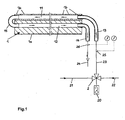
- the supporting or stripping strip 1 consists of a carrier strip 1a with ceramic elements 1b fastened thereto, wherein the supporting or stripping strip 1 is formed with two channels 11 and 12. At one end of the support or squeegee 1 close to the mouths of the two channels 11 and 12 connecting pipes 13 and 14 at. At the other end of the support or
- the two channels 11 and 12 are connected to each other by means of a piece of pipe 15.
- the output line 23 of a mixing valve 2 is connected, which is supplied via a first connecting line 21, a carrier medium for cold and a second connecting line 22, a carrier medium for heat.
- a control device 20 the temperature of the dispensed from the mixing valve 2 via the output line 23 carrier medium is set to that value, which temperature value that support or stripping 1 in the system should have, which is fed via the mixing valve 2 with carrier medium.
- a support or stripping strip 1 located in a certain area of the installation should have. Then the mixing valve 2 is set to this temperature. As a result, this strip 1 is brought to the desired temperature by means of the supporting or stripping 1 via the output line 23 of the mixing valve 2 supplied carrier medium. The effluent from the support or squeegee 1 via the pipe 14, heated or cooled by this carrier medium is discharged via a further line 24 either in a memory or in the channel.
- temperature sensors 25 and 26 are further provided, by means of which the temperatures of the carrier medium flowing through these lines are detected.
- the temperature of the respective support or stripping bar 1 can be brought approximately to the desired value in the rule.
- the support or squeegee 1 is associated with a self-contained line circuit 3 for a carrier medium for heat or cold, in which a memory 30 for the carrier medium, a feed pump 4, a control valve 5, a heater 6 and a cooling device 7 are located. Furthermore, a control unit 8 is provided, which are assigned to two located in the line circuit 3 temperature sensors 81 and 82 and which serve to control the feed pump 4, the control valve 5, the heater 6 and the cooling device 7.
- temperature sensor 81 located in the line 35 takes place a temperature measurement of the support or stripping 1 inflowing carrier medium and by means of located in the line 36 temperature sensor 82 is a temperature measurement of the effluent from the stripping or scraper 1 medium.
- the measured values output by the temperature sensors 81 and 82 are transmitted via control lines 83 and 84 to the control unit 8, by means of which the feed pump 4, the control valve 5, the heating device 6 and the cooling device 7 are controlled via control lines 85, 86, 87 and 88.
- the control valve 5 is redirected to the effect that the carrier medium is supplied by means of the feed pump 4 of the heater 6, in which it is heated, whereupon it is passed via the connecting pipe 13 into the channel 11. This procedure is maintained until the support or squeegee 1 has the required temperature for the particular operating case. Soferne contrast, it is determined by the control unit 8 that the existing in the support or stripping 1 temperature must be reduced, the control valve 5 is redirected to the effect that the carrier medium is fed by means of the pump 4 of the cooling device 7, in which it is cooled , whereupon it is also passed via the connecting pipe 13 into the channel 11. This procedure is also maintained until the support or squeegee 1 has the required temperature for the particular operating case.
- a further control with regard to the heating or cooling of the supporting or stripping strip 1 can also take place in that the power of the conveying pump 4 is increased or decreased by the control unit 8.
- Soferne in operation of a plant for paper production by one of the support or squeegee 1 associated control unit 8 is determined that this support or squeegee 1 has a too low or too high temperature for the relevant operating case or too rapid a change in temperature this support or stripping 1 takes place, whereby in each case there is the risk of cracking or fractures of the ceramic elements 1 b of this support or stripping 1, this support or stripping 1 is supplied according to heated or cooled support medium, whereby the ceramic Elements 1b are not exposed to unacceptable thermal loads, thereby preventing damage caused thereby.
- Fig. 10, 10a and 10b Several embodiments of support or squeegee 1 are shown, which consist of support strips 1a with attached to these plates 1b made of ceramic material and which are formed with channels 11 and 12, which enforce this support or squeegee 1 in the longitudinal direction. These channels can begin at one end of the support or squeegee 1 and end at the other end of the strips 1. Alternatively, these channels may begin at one end of the squeegee 1 and be returned to that end. Furthermore, these channels can pass through the ceramic plates 1 b or be provided in the support bar 1 a or be located between the ceramic plates 1 b and the support bar 1 a. Furthermore, the channels may be formed with different cross sections.
- the arrangement of the channels within the support or squeegee or the formation of the cross section is of crucial importance to ensure that the targeted by the carrier medium flowing through this Temperature of the plates 1 b made of ceramic material is achieved in order to avoid their damage by thermal stresses.
- a carrier medium for cold or for heat in particular water is used as a carrier medium for cold or for heat in particular water.
Abstract
Description
Die gegenständliche Erfindung betrifft ein Verfahren zur Steuerung der Temperatur der keramischen Elemente einer Abstütz- bzw. Abstreifleiste, welche in einer Anlage zur Papiererzeugung dem in dieser befindlichen mindestens einen Siebband bzw. mindestens einen Filzband zugeordnet ist. Weiters betrifft die Erfindung eine Einrichtung sowie eine Abstütz- bzw. Abstreifleiste zur Durchführung dieses Verfahrens.The subject invention relates to a method for controlling the temperature of the ceramic elements of a support or squeegee, which is assigned in a plant for paper production to the located therein at least one screen belt or at least one felt belt. Furthermore, the invention relates to a device and a support or squeegee for performing this method.
Anlagen zur Papiererzeugung weisen mindestens ein Siebband und weiters mindestens ein Filzband auf, welchen beiden Bändern in deren Bewegungsrichtung aufeinanderfolgende, quer zu den Bändern ausgerichtete Abstützleisten zugeordnet sind, über welche das Siebband und das Filzband geführt sind. In einem ersten Bereich der Papiererzeugungsanlage dienen die Abstützleisten auch als Abstreifleisten für die aus dem Papierbrei austretenden und das Siebband durchsetzenden Flüssigkeiten. Da diese Abstützleisten großen mechanischen und korrodierenden Belastungen ausgesetzt sind, besteht das Erfordernis, diese an ihren den Siebbändern bzw. den Filzbändern zugewandten Oberflächen mit Platten aus einem keramischen Material zu versehen, an welche das Siebband bzw. das Filzband zur Anlage kommen.Equipment for paper production have at least one screen belt and further at least one felt belt, which are assigned to the two bands in their direction of succession, aligned transversely to the bands supporting strips over which the screen belt and the felt belt are guided. In a first area of the paper-making plant, the support strips also serve as squeegee strips for the liquids emerging from the paper pulp and passing through the sieve belt. Since these Abstützleisten are exposed to large mechanical and corrosive loads, there is a need to provide these on their the Siebbändern or the felt tapes facing surfaces with plates of a ceramic material to which the screen belt or the felt belt to the plant.
Einerseits werden das Siebband bzw. das Filzband mit sehr hohen Geschwindigkeiten von z.B. 40 m/sec über die Abstützleisten hinweg bewegt. Andererseits befinden sich unterhalb der Abstützleisten Einrichtungen zum Absaugen der aus dem Papierbrei austretenden Flüssigkeiten bzw. zum Ansaugen von Luft zur Trocknung des auf dem Siebband aufliegenden Papierbandes bzw. zum Trocknen des Filzbandes, wodurch das Siebband bzw. das Filzband auf die Abstützleisten mit sehr hohem Druck aufliegen. Hierdurch treten Reibungskräfte auf, durch welche die keramischen Elemente stark erhitzt werden können.On the one hand, the screen belt or the felt belt at very high speeds of e.g. Moved 40 m / sec over the Abstützleisten away. On the other hand, there are below the support strips means for sucking the emerging from the pulp liquids or for sucking air to dry the paper belt resting on the wire belt or for drying the felt belt, whereby the wire belt or the felt on the support bars with very high pressure rest. As a result, frictional forces occur, by which the ceramic elements can be heated strongly.
Soferne sich die Anlage zur Papiererzeugung außer Betrieb befindet, kühlen die Abstützleisten auf die Umgebungstemperatur ab. Sobald die Anlage in Betrieb genommen wird, wird auf das Siebband der Papierbrei aufgesprüht, welcher eine Temperatur von bis zu 90° aufweisen kann. Weiters kann oberhalb des Siebbandes eine Dampfhaube vorgesehen sein, innerhalb welcher sich Heißdampf befindet, welcher zur Trocknung des Papierbandes dient und durch welchen die keramischen Elemente mit Temperaturen bis zu 150 ° C beaufschlagt werden können. Dabei ist weiters zu berücksichtigen, dass die keramischen Elemente der Abstütz- bzw. Abstreifleisten eine sehr niedrige Wärmeleitfähigkeit aufweisen.As soon as the plant for paper production is out of operation, the support strips cool down to the ambient temperature. As soon as the system is put into operation, the paper pulp is sprayed onto the sieve belt, which can have a temperature of up to 90 °. Furthermore, above the screen belt, a steam hood can be provided, within which superheated steam is located, which serves to dry the paper tape and through which the ceramic elements can be subjected to temperatures up to 150 ° C. It should also be noted that the ceramic elements of the support or squeegee have a very low thermal conductivity.
Aufgrund der vorstehend dargelegten Sachverhalte unterliegen die keramischen Elemente der Abstütz- bzw. Abstreifleisten sehr hohen thermischen Belastungen, welche sich innerhalb sehr kurzer Zeiträume innerhalb eines Bereiches von etwa 200 ° C ändern können.Due to the circumstances outlined above, the ceramic elements of the supporting or wiper strips are subject to very high thermal stresses, which can change within a very short time within a range of about 200 ° C.
Durch diese thermischen Belastungen besteht die Gefahr, dass in den keramischen Elementen Risse bzw. Brüche auftreten. Dabei besteht das Erfordernis, die Abstütz- bzw. Abstreifleisten umgehend auszuwechseln, da andernfalls das Siebband bzw. das Filzband beschädigt werden, wodurch der Erzeugungsvorgang beeinträchtigt und Betriebsausfälle bedingt werden können.
Aufgrund der vorstehend erläuterten Sachverhalte müssen bei derartigen Anlagen aufgrund von hohen Temperaturschwankungen verursachte Schädigungen der keramischen Elemente unbedingt vermieden werden.As a result of these thermal stresses, there is a risk of cracks or breaks occurring in the ceramic elements. There is a need to replace the support or squeegee immediately, otherwise the screen belt or the felt belt are damaged, whereby the production process affected and operational failures can be conditional.
Due to the circumstances described above, damage to the ceramic elements caused by high temperature fluctuations must be avoided in such systems absolutely.
Aus der
Gemäß der
Diese Verfahren entsprechen jedoch deshalb nicht den bei derartigen Anlagen bestehenden Erfordernissen, da in unterschiedlichen Bereichen der Anlage zur Papiererzeugung und insbesondere in den einzelnen Abstütz- bzw. Abstreifleisten unterschiedliche thermische Bedingungen auftreten, weswegen durch eine Steuerung der gesamten Anlage und von Bereichen derselben unzulässige thermische Belastungen der auf den einzelnen Abstütz- bzw. Abstreifleisten vorgesehenen keramischen Elemente nicht vermieden werden können.However, these methods do not correspond to the existing requirements for such systems, since different thermal conditions occur in different areas of the plant for paper production and in particular in the individual support or squeegee, which is why by controlling the entire system and areas of the same unacceptable thermal loads the provided on the individual support or squeegee ceramic elements can not be avoided.
Der gegenständlichen Erfindung liegt somit die Aufgabe zugrunde, ein Verfahren zu schaffen, durch welches die einzelnen sich in einer Anlage zur Papiererzeugung befindlichen Abstütz- bzw. Abstreifleisten davor geschützt werden können, infolge von in diesen auftretenden thermischen Spannungen beschädigt zu werden. Dies wird erfindungsgemäß dadurch erzielt, dass die Abstütz- bzw. Abstreifleiste mit mindestens einem Kanal ausgebildet ist, durch welchen ein Trägermedium für Wärme bzw. für Kälte hindurchgeleitet wird.The subject invention is therefore based on the object to provide a method by which the individual located in a plant for paper production support or squeegee can be protected from being damaged due to occurring in these thermal stresses. this will According to the invention achieved in that the support or squeegee is formed with at least one channel through which a carrier medium for heat or for cold is passed.
Nach einem ersten bevorzugten Verfahren ist in der zu dem mindestens einen Kanal führenden Leitung ein Mischventil vorgesehen, an welches Leitungen für Trägermedien für Wärme bzw. für Kälte angeschlossen sind und welches auf diejenige Temperatur eingestellt wird, welche die betreffende Abstütz- bzw. Abstreifleiste aufweisen soll. Dabei kann in der von der Abstütz- bzw. Abstreifleiste wegführenden Leitung ein Temperatursensor vorgesehen sein, durch welchen die Temperatur des aus der Abstütz- bzw. Abstreifleiste abströmenden Trägermediums gemessen wird. Zudem kann auch in der zur Abstütz- bzw. Abstreifleiste hinführenden Leitung ein Temperatursensor vorgesehen sein, durch welchen die Temperatur des zur Abstütz- bzw. Abstreifleiste hinströmenden Trägermediums gemessen wird.According to a first preferred method, a mixing valve is provided in the line leading to the at least one channel, are connected to which lines for carrier media for heat or for cold and which is set to the temperature which should have the respective support or squeegee , In this case, a temperature sensor may be provided in the leading away from the support or squeegee line, by which the temperature of the effluent from the supporting or squeegee carrier medium is measured. In addition, a temperature sensor can also be provided in the line leading to the support or stripping bar, by means of which the temperature of the support medium flowing toward the support or stripping bar is measured.
Nach einem zweiten bevorzugten Verfahren wird die Temperatur des der Abstütz- bzw. Abstreifleiste zuströmenden Trägermediums in Abhängigkeit von der Temperatur des von dieser abströmenden Trägermediums gesteuert. Dabei kann das Trägermedium mittels einer Förderpumpe in einem in sich geschlossenen Leitungskreis gefördert werden. Weiters kann das von der Abstütz- bzw. Abstreifleiste abströmende Trägermedium entweder über eine Heizeinrichtung oder über eine Kühleinrichtung geleitet und hierauf der Abstütz- bzw. Abstreifleiste zugeführt werden. Die Heizeinrichtung bzw. die Kühleinrichtung können in Abhängigkeit von der Temperatur des von der Abstütz- bzw. Abstreifleiste abströmenden Trägermediums gesteuert werden.
Alternativ dazu kann die Leistung der Förderpumpe in Abhängigkeit von der Temperatur des von der Abstütz- bzw. Abstreifleiste abströmenden Trägermediums gesteuert werden. Zudem können sowohl die Leistungen der Heizeinrichtung bzw. der Kühleinrichtung als auch die Leistung der Förderpumpe in Abhängigkeit der Temperatur des von der Abstütz- bzw. Abstreifleiste abströmenden Trägermediums gesteuert werden. Vorzugsweise wird das Trägermedium durch die Abstütz- bzw. Abstreifleiste kontinuierlich hindurchgeleitet, wobei es insbesondere durch die keramischen Elemente der Abstütz- bzw. Abstreifleiste hindurchgeleitet wird.In accordance with a second preferred method, the temperature of the carrier medium flowing in toward the support strip or scraper blade is controlled as a function of the temperature of the carrier medium flowing away from it. In this case, the carrier medium can be conveyed by means of a feed pump in a self-contained line circuit. Furthermore, the carrier medium flowing away from the supporting or wiper strip can either be conducted via a heating device or via a cooling device, and then the support or wiper strip can be supplied. The heating device or the cooling device can be controlled as a function of the temperature of the carrier medium flowing away from the supporting or wiping strip.
Alternatively, the power of the feed pump can be controlled as a function of the temperature of the carrier medium flowing away from the support strip or scraper blade. In addition, both the performance of the heating device or of the cooling device and the power of the feed pump can be controlled as a function of the temperature of the carrier medium flowing away from the support or wiper strip. Preferably, the carrier medium is passed continuously through the supporting or stripping bar, wherein it is in particular passed through the ceramic elements of the supporting or stripping bar.
Bei einer erfindungsgemäßen Anlage zur Durchführung dieses Verfahrens zur Steuerung der Temperatur der keramischen Elemente einer Abstütz- bzw. Abstreifleiste in einer Anlage zur Papiererzeugung ist die Abstütz- bzw. Abstreifleiste mit mindestens einem Kanal ausgebildet, an welchen Leitungen für zur Abstütz- bzw. Abstreifleiste zuströmendes Trägermedium und für von dieser abströmendes Trägermedium angeschlossen sind.
Nach einer ersten Ausführungsform befindet sich in der zu dem mindestens einen Kanal hinführenden Leitung ein Mischventil für Trägermedien von Wärme und von Kälte. Weiters kann sich in der zur Abstütz- bzw. Abstreifleiste hinführenden Leitung und bzw. oder in der von der Abstütz- bzw. Absteifleiste wegführenden Leitung ein Temperatursensor befinden.In a system according to the invention for carrying out this method for controlling the temperature of the ceramic elements of a support or squeegee in a plant for paper production, the support or squeegee is formed with at least one channel, are connected to which lines for the support or squeegee inflowing carrier medium and for this flowing from the carrier medium.
According to a first embodiment, a mixing valve for carrier media of heat and cold is located in the line leading to the at least one channel. Furthermore, a temperature sensor may be located in the line leading to the support or stripping bar and / or in the line leading away from the support or stiffening bar.
Nach der zweiten Ausführungsform ist ein Leitungssystem vorgesehen, in welchem sich eine Förderpumpe, eine Heizeinrichtung und eine Kühleinrichtung für das Trägermedium befinden, wobei weiters mindestens ein Temperatursensor zur Ermittlung der Temperatur des von der Abstütz- bzw. Abstreifleiste abströmenden Trägermediums sowie eine Steuereinheit zur Steuerung der Leistungen der Heizeinrichtung und der Kühleinrichtung und bzw. oder der Förderpumpe vorgesehen sind. Dabei kann auch mindestens ein Temperatursensor zur Ermittlung der Temperatur des der Abstütz- bzw. Abstreifleiste zugeführten Trägermediums vorgesehen sein.According to the second embodiment, a line system is provided, in which there are a feed pump, a heater and a cooling device for the carrier medium, wherein at least one temperature sensor for determining the temperature of the effluent from the support or squeegee carrier medium and a control unit for controlling the Benefits of the heater and the cooling device and or or the feed pump are provided. In this case, at least one temperature sensor for determining the temperature of the supporting or stripping bar supplied carrier medium may be provided.
Eine erfindungsgemäße Abstütz- bzw. Abstreifleiste zur Durchführung dieses Verfahrens ist mit mindestens einem Kanal zur Leitung eines Trägermediums für Wärme bzw. für Kälte ausgebildet. Dabei kann der Kanal die keramischen Elemente durchsetzen. Weiters kann sich der Kanal zwischen den keramischen Elementen und einer Trägerleiste für die keramischen Elemente befinden. Zudem kann der Kanal an einem Ende der Abstütz- bzw. Abstreifleiste beginnen und am anderen Ende derselben enden bzw. kann der Kanal an einem Ende der Abstütz- bzw. Abstreifleiste beginnen und in dieser zum gleichen Ende zurückgeführt sein. Dabei kann der vorlaufende Kanal mit dem rücklaufenden Kanal innerhalb der Abstütz- bzw. Abstreifleiste verbunden sein. Zudem kann der vorlaufende Kanal mit dem rücklaufenden Kanal über ein außerhalb der Abstütz- bzw. Abstreifleiste befindliches Rohrstück verbunden sein. Weiters können sowohl die keramischen Elemente als auch die Trägerleiste mit mindestens einem Kanal bzw. mit Kanalstücken ausgebildet sein.An inventive support or squeegee for carrying out this method is formed with at least one channel for conducting a carrier medium for heat or for cold. The channel can pass through the ceramic elements. Furthermore, the channel can be located between the ceramic elements and a carrier strip for the ceramic elements. In addition, the channel may begin at one end of the support strip and terminate at the other end thereof, or the channel may begin at one end of the support strip and be returned thereto to the same end. In this case, the leading channel can be connected to the returning channel within the support or squeegee. In addition, the leading channel can be connected to the returning channel via a piece of pipe located outside the support or wiper strip. Furthermore, both the ceramic elements and the carrier strip can be formed with at least one channel or channel pieces.
Das erfindungsgemäße Verfahren, eine erfindungsgemäße Anlage und eine erfindungsgemäße Abstütz- bzw. Abstreifleiste sind nachstehend anhand von in der Zeichnung dargestellten Ausführungsbeispielen näher erläutert.The inventive method, a system according to the invention and a support or stripping strip according to the invention are explained below with reference to embodiments shown in the drawing.
Es zeigen:
-
Fig.1 eine Einrichtung zur Durchführung eines ersten erfindungsgemäßen Verfahrens, in schematischer Darstellung; -
Fig.2 eine Einrichtung zur Durchführung eines zweiten erfindungsgemäßen Verfahrens, in schematischer Darstellung; - die
Fig.3 und Fig.3a eine erste Ausführungsform einer erfindungsgemäßen Abstütz- bzw. Abstreifleiste, im Längsschnitt sowie im Schnitt nach der Linie A-A derFig.3 ; - die
Fig.4 und Fig.4a, 4b, 4c sowie 4d zweite Ausführungsformen einer erfindungsgemäßen Abstütz- bzw. Abstreifleiste, im Längsschnitt sowie in Schnitten nach der Linie B-B derFig.4 ; - die
Fig.5 und Fig.5a eine dritte Ausführungsform einer erfindungsgemäßen Abstütz- bzw. Abstreifleiste, im Längsschnitt sowie im Schnitt nach der Linie C-C derFig.5 ; -
Fig.6 eine vierte Ausführungsform einer erfindungsgemäßen Abstütz- bzw. Abstreifleiste, im Längsschnitt; - die
Fig.7 und Fig.7a, 7b sowie 7c fünfte Ausführungsformen einer erfindungsgemäßen Abstütz- bzw. Abstreifleiste, im Längsschnitt sowie in den Schnitten nach der Linie D-D derFig.7 ; - die
Fig.8 und Fig.8a sowie 8b sechste Ausführungsformen einer erfindungsgemäßen Abstütz- bzw. Abstreifleiste, im Längsschnitt sowie in Schnitten nach der Linie E-E derFig.8 ; - die
Fig.9 und Fig.9a eine siebente Ausführungsform einer erfindungsgemäßen Abstütz- bzw. Abstreifleiste, im Längsschnitt sowie im Schnitt nach der Linie F-F derFig.9 ; und - die
Fig. 10, 10a und 10b achte Ausführungsformen einer erfindungsgemäßen Abstütz- bzw. Abstreifleiste, im Längsschnitt sowie im Schnitt nach der Linie G-G derFig.10 bzw. im Schnitt nach der Linie H-H derFig.10 .
-
Fig.1 a device for carrying out a first method according to the invention, in a schematic representation; -
Fig.2 a device for carrying out a second method according to the invention, in a schematic representation; - the
3 and 3a a first embodiment of a support strip or strip according to the invention, in longitudinal section and in section along the line AAFigure 3 ; - the
4 and 4a, 4b, 4c and 4d second embodiments of a support or stripping strip according to the invention, in longitudinal section and in sections along the line BB of theFigure 4 ; - the
Fig.5 and 5a a third embodiment of a support strip or strip according to the invention, in longitudinal section and in section along the line CC ofFigure 5 ; -
Figure 6 a fourth embodiment of a support or wiper strip according to the invention, in longitudinal section; - the
Fig.7 and Fig.7a, 7b and 7c Fifth embodiments of a support or stripping strip according to the invention, in longitudinal section and in the sections along the line DD ofFigure 7 ; - the
Fig.8 and Fig. 8a and 8b sixth embodiments of a supporting or stripping strip according to the invention, in longitudinal section and in sections along the line EE of FIGFigure 8 ; - the
Fig.9 and Fig.9a a seventh embodiment of a supporting or stripping strip according to the invention, in longitudinal section and in section along the line FF ofFigure 9 ; and - the
Fig. 10, 10a and 10b eighth embodiments of a support or stripping strip according to the invention, in longitudinal section and in section along the line GG ofFigure 10 or in section along the line HH theFigure 10 ,
Anhand der
Abstreifleiste 1 sind die beiden Kanäle 11 und 12 mittels eines Rohrstückes 15 miteinander verbunden.
An das Anschlussrohr 13 ist die Ausgangsleitung 23 eines Mischventiles 2 angeschlossen, welchem über eine erste Anschlussleitung 21 ein Trägermedium für Kälte und über eine zweite Anschlussleitung 22 ein Trägermedium für Wärme zugeleitet wird. Mittels eines Regelgerätes 20 wird die Temperatur des vom Mischventil 2 über die Ausgangsleitung 23 abgegebenen Trägermediums auf denjenigen Wert eingestellt, welchen Temperaturwert diejenige Abstütz- bzw. Abstreifleiste 1 in der Anlage aufweisen soll, welche über das Mischventil 2 mit Trägermedium gespeist wird.
To the connecting
Im Betrieb der Anlage zur Papiererzeugung wird festgelegt, welche Temperatur eine in einem bestimmten Bereich der Anlage befindliche Abstütz- bzw. Abstreifleiste 1 aufweisen soll. Hierauf wird das Mischventil 2 auf diese Temperatur eingestellt. Hierdurch wird mittels des der Abstütz- bzw. Abstreifleiste 1 über die Ausgangsleitung 23 des Mischventiles 2 zugeführten Trägermediums diese Leiste 1 auf die angestrebte Temperatur gebracht. Das von der Abstütz- bzw. Abstreifleiste 1 über das Rohr 14 abströmende, durch diese erwärmte oder abgekühlte Trägermedium wird über eine weitere Leitung 24 entweder in einen Speicher oder in den Kanal abgeleitet.During operation of the plant for paper production, it is determined which temperature a support or stripping
In den Leitungen 23 und 24 sind weiters Temperatursensoren 25 und 26 vorgesehen, mittels welcher die Temperaturen des durch diese Leitungen hindurchströmenden Trägermediums erfasst werden.In the
Durch dieses Verfahren kann in der Regel die Temperatur der betreffenden Abstütz- bzw. Abstreifleiste 1 angenähert auf den angestrebten Wert gebracht werden.By this method, the temperature of the respective support or stripping
Gemäß dem anhand der
Die Wirkungsweise dieser Einrichtung ist wie folgt:
- Mittels der Förderpumpe 4 wird Trägermedium für Wärme oder Kälte über eine Leitung 31
zum Steuerventil 5 geleitet, von welchem es entweder über eine Leitung 32zur Heizeinrichtung 6 oder über eine Leitung 34 zur Kühleinrichtung 7 gefördert wird.Von der Heizeinrichtung 6 bzw. von der Kühleinrichtung 7 gelangt erwärmtes bzw. abgekühltes Trägermedium über Leitungen 33 bzw. 35 und überdas Anschlussrohr 13 inden Kanal 11 der Abstütz- bzw.Abstreifleiste 1 sowie überdas Rohrstück 15 inden Kanal 12. Der Rückfluss des Trägermediums erfolgt überdas Rohr 14 und eine Leitung 36 zur Förderpumpe 4.
- By means of the feed pump 4 carrier medium for heat or cold is passed via a
line 31 to thecontrol valve 5, from which it is conveyed either via aline 32 to theheater 6 or via aline 34 to the cooling device 7. From theheating device 6 or from the cooling device 7 is heated or cooled carrier medium vialines tube 13 in thechannel 11 of the support orsqueegee 1 and via thepipe section 15 in thechannel 12. The reflux The carrier medium via thetube 14 and aline 36 to the feed pump. 4
Mittels des in der Leitung 35 befindlichen ersten Temperatursensors 81 erfolgt eine Temperaturmessung des der Abstütz- bzw. Abstreifleiste 1 zuströmenden Trägermediums und mittels des in der Leitung 36 befindlichen Temperatursensors 82 erfolgt eine Temperaturmessung des von der Abstütz- bzw. Abstreifleiste 1 abströmenden Mediums. Die von den Temperatursensoren 81 und 82 abgegebenen Messwerte werden über Steuerleitungen 83 und 84 an die Steuereinheit 8 übertragen, von welcher über Steuerleitungen 85, 86, 87 und 88 die Förderpumpe 4, das Steuerventil 5, die Heizeinrichtung 6 und die Kühleinrichtung 7 gesteuert werden.By means of the first temperature sensor 81 located in the
Sobald durch die Steuereinheit 8 aufgrund des vom Temperatursensor 82 abgegebenen Messwertes festgestellt wird, dass die in der Abstützleiste 1 bestehende Temperatur erhöht werden muss, wird das Regelventil 5 dahingehend umgesteuert, dass das Trägermedium mittels der Förderpumpe 4 der Heizeinrichtung 6 zugeleitet wird, in welcher es erhitzt wird, worauf es über das Anschlussrohr 13 in den Kanal 11 geleitet wird. Diese Verfahrensweise wird so lange beibehalten, bis die Abstütz- bzw. Abstreifleiste 1 die für den bestimmten Betriebsfall erforderliche Temperatur aufweist.
Soferne demgegenüber durch die Steuereinheit 8 festgestellt wird, dass die in der Abstütz- bzw. Abstreifleiste 1 bestehende Temperatur verringert werden muss, wird das Regelventil 5 dahingehend umgesteuert, dass das Trägermedium mittels der Förderpumpe 4 der Kühleinrichtung 7 zugeleitet wird, in welcher es abgekühlt wird, worauf es gleichfalls über das Anschlussrohr 13 in den Kanal 11 geleitet wird.
Diese Verfahrensweise wird gleichfalls so lange beibehalten, bis die Abstütz- bzw. Abstreifleiste 1 die für den bestimmten Betriebsfall erforderliche Temperatur aufweist.Once it is determined by the control unit 8 due to the output by the
Soferne contrast, it is determined by the control unit 8 that the existing in the support or stripping 1 temperature must be reduced, the
This procedure is also maintained until the support or
Ein weitere Steuerung hinsichtlich der Erwärmung bzw. Abkühlung der Abstütz- bzw. Abstreifleiste 1 kann auch dadurch erfolgen, dass durch die Steuereinheit 8 die Leistung der Förderpumpe 4 erhöht bzw. abgesenkt wird.
Soferne im Betrieb einer Anlage zur Papiererzeugung durch die einer der Abstütz- bzw. Abstreifleisten 1 zugeordnete Steuereinheit 8 festgestellt wird, dass diese Abstütz- bzw. Abstreifleiste 1 eine für den betreffenden Betriebsfall zu geringe oder zu hohe Temperatur aufweist oder ein zu rasche Änderung der Temperatur dieser Abstütz- bzw. Abstreifleiste 1 erfolgt, wodurch jeweils die Gefahr von Rissbildungen bzw. von Brüchen der keramischen Elemente 1b dieser Abstütz- bzw. Abstreifleiste 1 besteht, wird dieser Abstütz- bzw. Abstreifleiste 1 entsprechend erwärmtes oder gekühltes Trägermedium zugeführt, wodurch die keramischen Elemente 1b keinen unzulässigen thermischen Belastungen ausgesetzt werden, sodass hierdurch verursachte Schädigungen vermieden werden.A further control with regard to the heating or cooling of the supporting or stripping
Soferne in operation of a plant for paper production by one of the support or
Durch dieses zweite Verfahren erfolgt unabhängig von den besonderen Betriebsumständen eine weitgehend genaue Steuerung der Temperatur der betreffenden Abstütz- bzw. Abstreifleiste.By means of this second method, a largely accurate control of the temperature of the respective support or wiper strip takes place, independently of the particular operating circumstances.
In den
Da die Platten 1b aus keramischem Material eine sehr geringe Wärmeleitfähigkeit aufweisen, kommt der Anordnung der Kanäle innerhalb der Abstütz- bzw. Abstreifleisten bzw. der Ausbildung des Querschnittes eine maßgebliche Bedeutung zu, um zu gewährleisten, dass durch das diese durchströmende Trägermedium die angestrebte Temperatur der Platten 1b aus keramischem Material erzielt wird, um deren Beschädigung durch Wärmespannungen zu vermeiden.
Als Trägermedium für Kälte bzw. für Wärme wird insbesondere Wasser verwendet.Since the
As a carrier medium for cold or for heat in particular water is used.
Claims (25)
- A method of controlling the temperature of the ceramic elements (1b) of a supporting or scraper bar (1), which is associated in a papermaking installation with the at least one screen belt or at least one felt belt located therein, characterised in that the supporting or scraper bar (1) is constructed with at least one channel (11, 12), through which a carrier medium for heat or cold is passed.
- A method according to claim 1, characterised in that a mixing valve (2) is provided in the line leading to the at least one channel (11, 12), to which mixing valve (2) lines (21, 22) for carrier media for heat or cold are connected and which is set to the temperature which the relevant supporting or scraper bar (1) is intended to exhibit.
- A method according to either one of claims 1 and 2, characterised in that a temperature sensor (15) is provided in the line (26) leading away from the supporting or scraper bar (1), which temperature sensor (15) measures the temperature of the carrier medium flowing away from the supporting or scraper bar (1).
- A method according to any one of claims 1 to 3, characterised in that a temperature sensor (25) is provided in the line (23) leading towards the supporting or scraper bar (1), which temperature sensor (25) measures the temperature of the carrier medium flowing towards the supporting or scraper bar (1).
- A method according to claim 1, characterised in that the temperature of the carrier medium flowing to the supporting or scraper bar (1) is controlled as a function of the temperature of the carrier medium flowing away therefrom.
- A method according to claim 5, characterised in that the carrier medium is conveyed by means of a feed pump (4) in a continuous line circuit (3).
- A method according to either one of claims 5 and 6, characterised in that the carrier medium flowing away from the supporting or scraper bar (1) passes either through a heating device (6) or through a cooling device (7) and is then fed to the supporting or scraper bar (1).
- A method according to claim 7, characterised in that the heating device (6) or the cooling device (7) is controlled as a function of the temperature of the carrier medium flowing away from the supporting or scraper bar (1).
- A method according to claim 7, characterised in that the output of the feed pump (4) is controlled as a function of the temperature of the carrier medium flowing away from the supporting or scraper bar (1).
- A method according to claim 7, characterised in that the outputs of the heating device (6) or the cooling device (7) and the output of the feed pump (4) are controlled as a function of the temperature of the carrier medium flowing away from the supporting or scraper bar (1).
- A method according to any one of claims 1 to 10, characterised in that the carrier medium is passed continuously through the supporting or scraper bar (1).
- A method according to any one of claims 1 to 11, characterised in that the carrier medium is passed continuously through the ceramic elements (1b) of the supporting or scraper bar (1).
- An installation for carrying out the method according to any one of claims 1 to 12, characterised in that the supporting or scraper bar (1) is constructed with at least one channel (11, 12), to which are connected a line (13) for carrier medium flowing towards the supporting or scraper bar (1) and a line (14) for carrier medium flowing away therefrom.
- An installation according to claim 13, characterised in that a mixing valve (2) for carrier media for heat and cold is located in the line (23) leading to the at least one channel (11, 12).
- An installation according to claim 14, characterised in that a temperature sensor (25, 26) is located in the line (23) leading towards the supporting or scraper bar (1) and/or in the line (24) leading away therefrom.
- An installation according to claim 13, characterised in that a line system (3) is provided, in which there are located a feed pump (4) for the carrier medium and a heating device (6) and a cooling device (7) for the carrier medium and in that in addition there are provided at least one temperature sensor (82) for determining the temperature of the carrier medium flowing away from the supporting or scraper bar (1) and a control unit (8) for controlling the outputs of the heating device (6) and the cooling device (7) and/or the feed pump (4).
- An installation according to claim 16, characterised in that at least one temperature sensor (81) for determining the temperature of the carrier medium fed to the supporting or scraper bar (1) is also provided.
- A supporting or scraper bar (1) for carrying out the method according to any one of claims 1 to 12 or for an installation according to any one of claims 13 to 17, characterised in that it is constructed with at least one channel (11, 12) for conveying a carrier medium for heat or cold.
- A supporting or scraper bar (1) according to claim 18, characterised in that the channel (11) passes through the ceramic elements (1b).
- A supporting or scraper bar (1) according to claim 18, characterised in that the channel is located between the ceramic elements (1b) and a carrier bar (la) for the ceramic elements (1b).
- A supporting or scraper bar (1) according to any one of claims 18 to 20, characterised in that the channel starts at one end of the supporting or scraper bar (1) and ends at the other end thereof.
- A supporting or scraper bar (1) according to any one of claims 18 to 20, characterised in that the channel starts at one end of the supporting or scraper bar (1) and is returned therein to the same end.
- A supporting or scraper bar (1) according to claim 22, characterised in that the outward channel (11) is connected to the return channel (12) within the supporting or scraper bar (1).
- A supporting or scraper bar (1) according to claim 22, characterised in that the outward channel (11) is connected to the return channel (12) by means of a pipe piece (15) located outside the supporting or scraper bar (1).
- A supporting or scraper bar according to any one of claims 18 to 24, characterised in that both the ceramic elements (1b) and the carrier bar (1a) are constructed with at least one channel or with channel pieces.
Priority Applications (1)
| Application Number | Priority Date | Filing Date | Title |
|---|---|---|---|
| AT06450181T ATE434682T1 (en) | 2006-04-13 | 2006-12-14 | METHOD FOR CONTROLLING THE TEMPERATURE OF THE CERAMIC ELEMENTS OF A SUPPORT OR SCRIPPER BAR IN A PAPER PRODUCING PLANT AS WELL AS DEVICE AND SUPPORT OR SCRIPPER BAR FOR PERFORMING THIS PROCEDURE |
Applications Claiming Priority (1)
| Application Number | Priority Date | Filing Date | Title |
|---|---|---|---|
| AT0064406A AT503404A1 (en) | 2006-04-13 | 2006-04-13 | METHOD FOR CONTROLLING THE TEMPERATURE OF THE CERAMIC ELEMENTS OF A SUPPORTING DEVICE DIVIDING STRIP IN A PAPER PRODUCTION PLANT AND DEVICE AND SUPPORTING DEVICE. SPREADING STRIP FOR CARRYING OUT THIS PROCEDURE |
Publications (3)
| Publication Number | Publication Date |
|---|---|
| EP1845189A2 EP1845189A2 (en) | 2007-10-17 |
| EP1845189A3 EP1845189A3 (en) | 2008-04-30 |
| EP1845189B1 true EP1845189B1 (en) | 2009-06-24 |
Family
ID=38283059
Family Applications (1)
| Application Number | Title | Priority Date | Filing Date |
|---|---|---|---|
| EP06450181A Not-in-force EP1845189B1 (en) | 2006-04-13 | 2006-12-14 | Method for controlling temperature of ceramic elements of a support or peel guide rail in a paper producing system and device and support or peel guide rail for carrying out this method |
Country Status (9)
| Country | Link |
|---|---|
| US (1) | US7550062B2 (en) |
| EP (1) | EP1845189B1 (en) |
| JP (1) | JP4859736B2 (en) |
| CN (1) | CN101054780B (en) |
| AT (2) | AT503404A1 (en) |
| BR (1) | BRPI0701985A (en) |
| CA (1) | CA2582017C (en) |
| DE (1) | DE502006004060D1 (en) |
| ES (1) | ES2326385T3 (en) |
Families Citing this family (1)
| Publication number | Priority date | Publication date | Assignee | Title |
|---|---|---|---|---|
| TWI686524B (en) * | 2016-12-13 | 2020-03-01 | 財團法人紡織產業綜合研究所 | Textile apparatus and thermal-energy adjusting method for the same |
Family Cites Families (10)
| Publication number | Priority date | Publication date | Assignee | Title |
|---|---|---|---|---|
| DE3128866A1 (en) * | 1981-07-22 | 1983-02-10 | Feldmühle AG, 4000 Düsseldorf | Paper machine |
| DE3421631C1 (en) * | 1984-06-09 | 1985-09-12 | Küsters, Eduard, 4150 Krefeld | Method for controlling the heating or cooling medium flow in a heatable or coolable roller and corresponding roller arrangement |
| DE3929265C2 (en) * | 1989-09-02 | 1997-05-07 | Voith Sulzer Papiermasch Gmbh | Strip for sheet formation zone of a paper machine |
| DE4028126C2 (en) * | 1990-09-05 | 1993-10-14 | Escher Wyss Gmbh | Slot nozzle, in particular for a twin wire former and their use in a twin wire former |
| DE4107653A1 (en) * | 1991-03-09 | 1992-09-10 | Escher Wyss Gmbh | DRAINAGE DEVICE FOR THE WET SECTION OF A PAPER MACHINE |
| US5314585A (en) * | 1993-05-10 | 1994-05-24 | Champion International Corporation | Low shear Uhle box |
| GB2370046A (en) * | 2000-12-15 | 2002-06-19 | Astenjohnson Inc | Adjustable resilient blade support |
| DE50209515D1 (en) * | 2001-05-15 | 2007-04-05 | Voith Patent Gmbh | Machine for producing a fibrous web from a pulp suspension, method for monitoring a dewatering element of a paper machine and paper machine with a system for monitoring a dewatering element |
| AT411536B (en) * | 2002-07-18 | 2004-02-25 | Bartelmuss Klaus Ing | PLANT FOR PRODUCING A PAPER TAPE WITH AT LEAST ONE ABOUT CARRYING OR GUIDED ROLLERS MOVED, CLOSED SCREEN |
| CN1648336A (en) * | 2004-01-20 | 2005-08-03 | 克劳斯·巴特尔马斯 | Device for producing paper web |
-
2006
- 2006-04-13 AT AT0064406A patent/AT503404A1/en not_active Application Discontinuation
- 2006-12-14 EP EP06450181A patent/EP1845189B1/en not_active Not-in-force
- 2006-12-14 ES ES06450181T patent/ES2326385T3/en active Active
- 2006-12-14 AT AT06450181T patent/ATE434682T1/en active
- 2006-12-14 DE DE502006004060T patent/DE502006004060D1/en active Active
-
2007
- 2007-03-16 CA CA2582017A patent/CA2582017C/en not_active Expired - Fee Related
- 2007-03-30 BR BRPI0701985-8A patent/BRPI0701985A/en not_active IP Right Cessation
- 2007-04-11 JP JP2007104155A patent/JP4859736B2/en not_active Expired - Fee Related
- 2007-04-12 CN CN2007100901099A patent/CN101054780B/en not_active Expired - Fee Related
- 2007-04-13 US US11/786,817 patent/US7550062B2/en not_active Expired - Fee Related
Also Published As
| Publication number | Publication date |
|---|---|
| CN101054780A (en) | 2007-10-17 |
| DE502006004060D1 (en) | 2009-08-06 |
| AT503404A1 (en) | 2007-10-15 |
| CN101054780B (en) | 2011-06-15 |
| US7550062B2 (en) | 2009-06-23 |
| JP4859736B2 (en) | 2012-01-25 |
| EP1845189A2 (en) | 2007-10-17 |
| CA2582017C (en) | 2013-03-19 |
| ES2326385T3 (en) | 2009-10-08 |
| BRPI0701985A (en) | 2007-11-27 |
| ATE434682T1 (en) | 2009-07-15 |
| US20070240840A1 (en) | 2007-10-18 |
| EP1845189A3 (en) | 2008-04-30 |
| JP2007284862A (en) | 2007-11-01 |
| CA2582017A1 (en) | 2007-10-13 |
Similar Documents
| Publication | Publication Date | Title |
|---|---|---|
| EP2643109B1 (en) | Method and device for the controlled secondary cooling of a continuous casting installation | |
| DE10122628A1 (en) | Separating plates from workpiece, especially semiconducting wafers from rod or block semiconducting material, involves measuring/regulating workpiece temperature during sawing | |
| DE102010013982A1 (en) | Apparatus for producing foam bitumen and method for its maintenance | |
| EP3158117B1 (en) | Oxidation furnace | |
| DE102014118946B4 (en) | Apparatus and method for the continuous treatment of a metal strip | |
| EP0073915B2 (en) | Method and apparatus to control a continuous thermal process for a textile sheet-like material | |
| EP1845189B1 (en) | Method for controlling temperature of ceramic elements of a support or peel guide rail in a paper producing system and device and support or peel guide rail for carrying out this method | |
| EP2459335A1 (en) | Device and method for the controlled secondary cooling of a strand casting system | |
| DE102005029461B3 (en) | Applying coolant to rolled stock and/or to working rolls in a roll stand comprises applying the coolant in an amount depending on the work done in the gap between the rolls | |
| DE102006043567A1 (en) | Spray bar of a hydraulic Entzunderungsanlage and method for operating such a spray bar | |
| WO2006136298A1 (en) | Air dome for a paper or cardboard machine | |
| EP2335000B1 (en) | Device for recovering heat on a system for the thermal treatment of textile material webs | |
| EP1382741A2 (en) | Apparatus for making a paper web with at least one endless screen belt guided by bearing and guide rollers | |
| EP1085122A2 (en) | Method and device for drying a web | |
| EP3209603B1 (en) | Device and method for cooling a fluid | |
| EP3360675B1 (en) | Continuous press for producing wood-based boards | |
| EP2324223A2 (en) | Device for continuously conditioning fed-out natural gas | |
| DE102006056518A1 (en) | Device for the floating guidance of sheet material | |
| DE102007055346A1 (en) | Casting machine with a device for application to a casting belt | |
| DE102012105529A1 (en) | Method for drying material web using steam generator, involves drying material web by stream of hot air, condensing steam in cylinder, exhausting hot air, and feeding condensate to steam generator, which is heated by exhausted hot air | |
| DE10123529A1 (en) | Fibrous web-manufacturing apparatus comprises temperature sensor connected to removable edge piece connected to format slide and/or drainage rail | |
| WO2008110319A1 (en) | Heat exchanger | |
| DE102008035202B3 (en) | Process for the purification of gases, in particular chemical residues | |
| DE102013223437A1 (en) | Apparatus for cooling or heating bulk materials | |
| EP4140593A1 (en) | Nozzle device and method for the production thereof |
Legal Events
| Date | Code | Title | Description |
|---|---|---|---|
| PUAI | Public reference made under article 153(3) epc to a published international application that has entered the european phase |
Free format text: ORIGINAL CODE: 0009012 |
|
| AK | Designated contracting states |
Kind code of ref document: A2 Designated state(s): AT BE BG CH CY CZ DE DK EE ES FI FR GB GR HU IE IS IT LI LT LU LV MC NL PL PT RO SE SI SK TR |
|
| AX | Request for extension of the european patent |
Extension state: AL BA HR MK YU |
|
| PUAL | Search report despatched |
Free format text: ORIGINAL CODE: 0009013 |
|
| AK | Designated contracting states |
Kind code of ref document: A3 Designated state(s): AT BE BG CH CY CZ DE DK EE ES FI FR GB GR HU IE IS IT LI LT LU LV MC NL PL PT RO SE SI SK TR |
|
| AX | Request for extension of the european patent |
Extension state: AL BA HR MK RS |
|
| 17P | Request for examination filed |
Effective date: 20080424 |
|
| AKX | Designation fees paid |
Designated state(s): AT BE BG CH CY CZ DE DK EE ES FI FR GB GR HU IE IS IT LI LT LU LV MC NL PL PT RO SE SI SK TR |
|
| GRAP | Despatch of communication of intention to grant a patent |
Free format text: ORIGINAL CODE: EPIDOSNIGR1 |
|
| GRAS | Grant fee paid |
Free format text: ORIGINAL CODE: EPIDOSNIGR3 |
|
| GRAA | (expected) grant |
Free format text: ORIGINAL CODE: 0009210 |
|
| AK | Designated contracting states |
Kind code of ref document: B1 Designated state(s): AT BE BG CH CY CZ DE DK EE ES FI FR GB GR HU IE IS IT LI LT LU LV MC NL PL PT RO SE SI SK TR |
|
| REG | Reference to a national code |
Ref country code: GB Ref legal event code: FG4D Free format text: NOT ENGLISH |
|
| REG | Reference to a national code |
Ref country code: CH Ref legal event code: NV Representative=s name: LUCHS & PARTNER PATENTANWAELTE Ref country code: CH Ref legal event code: EP |
|
| REG | Reference to a national code |
Ref country code: IE Ref legal event code: FG4D Free format text: LANGUAGE OF EP DOCUMENT: GERMAN |
|
| REF | Corresponds to: |
Ref document number: 502006004060 Country of ref document: DE Date of ref document: 20090806 Kind code of ref document: P |
|
| REG | Reference to a national code |
Ref country code: ES Ref legal event code: FG2A Ref document number: 2326385 Country of ref document: ES Kind code of ref document: T3 |
|
| REG | Reference to a national code |
Ref country code: SE Ref legal event code: TRGR |
|
| PG25 | Lapsed in a contracting state [announced via postgrant information from national office to epo] |
Ref country code: LT Free format text: LAPSE BECAUSE OF FAILURE TO SUBMIT A TRANSLATION OF THE DESCRIPTION OR TO PAY THE FEE WITHIN THE PRESCRIBED TIME-LIMIT Effective date: 20090624 |
|
| PG25 | Lapsed in a contracting state [announced via postgrant information from national office to epo] |
Ref country code: SI Free format text: LAPSE BECAUSE OF FAILURE TO SUBMIT A TRANSLATION OF THE DESCRIPTION OR TO PAY THE FEE WITHIN THE PRESCRIBED TIME-LIMIT Effective date: 20090624 Ref country code: LV Free format text: LAPSE BECAUSE OF FAILURE TO SUBMIT A TRANSLATION OF THE DESCRIPTION OR TO PAY THE FEE WITHIN THE PRESCRIBED TIME-LIMIT Effective date: 20090624 Ref country code: PL Free format text: LAPSE BECAUSE OF FAILURE TO SUBMIT A TRANSLATION OF THE DESCRIPTION OR TO PAY THE FEE WITHIN THE PRESCRIBED TIME-LIMIT Effective date: 20090624 |
|
| NLV1 | Nl: lapsed or annulled due to failure to fulfill the requirements of art. 29p and 29m of the patents act | ||
| PG25 | Lapsed in a contracting state [announced via postgrant information from national office to epo] |
Ref country code: IS Free format text: LAPSE BECAUSE OF FAILURE TO SUBMIT A TRANSLATION OF THE DESCRIPTION OR TO PAY THE FEE WITHIN THE PRESCRIBED TIME-LIMIT Effective date: 20091024 Ref country code: CZ Free format text: LAPSE BECAUSE OF FAILURE TO SUBMIT A TRANSLATION OF THE DESCRIPTION OR TO PAY THE FEE WITHIN THE PRESCRIBED TIME-LIMIT Effective date: 20090624 Ref country code: EE Free format text: LAPSE BECAUSE OF FAILURE TO SUBMIT A TRANSLATION OF THE DESCRIPTION OR TO PAY THE FEE WITHIN THE PRESCRIBED TIME-LIMIT Effective date: 20090624 |
|
| REG | Reference to a national code |
Ref country code: IE Ref legal event code: FD4D |
|
| PG25 | Lapsed in a contracting state [announced via postgrant information from national office to epo] |
Ref country code: NL Free format text: LAPSE BECAUSE OF FAILURE TO SUBMIT A TRANSLATION OF THE DESCRIPTION OR TO PAY THE FEE WITHIN THE PRESCRIBED TIME-LIMIT Effective date: 20090624 Ref country code: SK Free format text: LAPSE BECAUSE OF FAILURE TO SUBMIT A TRANSLATION OF THE DESCRIPTION OR TO PAY THE FEE WITHIN THE PRESCRIBED TIME-LIMIT Effective date: 20090624 |
|
| PG25 | Lapsed in a contracting state [announced via postgrant information from national office to epo] |
Ref country code: BG Free format text: LAPSE BECAUSE OF FAILURE TO SUBMIT A TRANSLATION OF THE DESCRIPTION OR TO PAY THE FEE WITHIN THE PRESCRIBED TIME-LIMIT Effective date: 20090924 Ref country code: PT Free format text: LAPSE BECAUSE OF FAILURE TO SUBMIT A TRANSLATION OF THE DESCRIPTION OR TO PAY THE FEE WITHIN THE PRESCRIBED TIME-LIMIT Effective date: 20091024 |
|
| PG25 | Lapsed in a contracting state [announced via postgrant information from national office to epo] |
Ref country code: DK Free format text: LAPSE BECAUSE OF FAILURE TO SUBMIT A TRANSLATION OF THE DESCRIPTION OR TO PAY THE FEE WITHIN THE PRESCRIBED TIME-LIMIT Effective date: 20090624 Ref country code: IE Free format text: LAPSE BECAUSE OF FAILURE TO SUBMIT A TRANSLATION OF THE DESCRIPTION OR TO PAY THE FEE WITHIN THE PRESCRIBED TIME-LIMIT Effective date: 20090624 |
|
| PLBE | No opposition filed within time limit |
Free format text: ORIGINAL CODE: 0009261 |
|
| STAA | Information on the status of an ep patent application or granted ep patent |
Free format text: STATUS: NO OPPOSITION FILED WITHIN TIME LIMIT |
|
| 26N | No opposition filed |
Effective date: 20100325 |
|
| BERE | Be: lapsed |
Owner name: BARTELMUSS, KLAUS Effective date: 20091231 Owner name: BARTELMUSS, HEINZ Effective date: 20091231 |
|
| PG25 | Lapsed in a contracting state [announced via postgrant information from national office to epo] |
Ref country code: MC Free format text: LAPSE BECAUSE OF NON-PAYMENT OF DUE FEES Effective date: 20100701 |
|
| PG25 | Lapsed in a contracting state [announced via postgrant information from national office to epo] |
Ref country code: BE Free format text: LAPSE BECAUSE OF NON-PAYMENT OF DUE FEES Effective date: 20091231 Ref country code: GR Free format text: LAPSE BECAUSE OF FAILURE TO SUBMIT A TRANSLATION OF THE DESCRIPTION OR TO PAY THE FEE WITHIN THE PRESCRIBED TIME-LIMIT Effective date: 20090925 |
|
| PG25 | Lapsed in a contracting state [announced via postgrant information from national office to epo] |
Ref country code: RO Free format text: LAPSE BECAUSE OF FAILURE TO SUBMIT A TRANSLATION OF THE DESCRIPTION OR TO PAY THE FEE WITHIN THE PRESCRIBED TIME-LIMIT Effective date: 20090624 |
|
| PG25 | Lapsed in a contracting state [announced via postgrant information from national office to epo] |
Ref country code: LU Free format text: LAPSE BECAUSE OF NON-PAYMENT OF DUE FEES Effective date: 20091214 |
|
| PG25 | Lapsed in a contracting state [announced via postgrant information from national office to epo] |
Ref country code: HU Free format text: LAPSE BECAUSE OF FAILURE TO SUBMIT A TRANSLATION OF THE DESCRIPTION OR TO PAY THE FEE WITHIN THE PRESCRIBED TIME-LIMIT Effective date: 20091225 |
|
| PG25 | Lapsed in a contracting state [announced via postgrant information from national office to epo] |
Ref country code: TR Free format text: LAPSE BECAUSE OF FAILURE TO SUBMIT A TRANSLATION OF THE DESCRIPTION OR TO PAY THE FEE WITHIN THE PRESCRIBED TIME-LIMIT Effective date: 20090624 |
|
| PG25 | Lapsed in a contracting state [announced via postgrant information from national office to epo] |
Ref country code: CY Free format text: LAPSE BECAUSE OF FAILURE TO SUBMIT A TRANSLATION OF THE DESCRIPTION OR TO PAY THE FEE WITHIN THE PRESCRIBED TIME-LIMIT Effective date: 20090624 |
|
| PGFP | Annual fee paid to national office [announced via postgrant information from national office to epo] |
Ref country code: FI Payment date: 20121212 Year of fee payment: 7 Ref country code: CH Payment date: 20121221 Year of fee payment: 7 |
|
| PGFP | Annual fee paid to national office [announced via postgrant information from national office to epo] |
Ref country code: GB Payment date: 20121220 Year of fee payment: 7 Ref country code: IT Payment date: 20121218 Year of fee payment: 7 Ref country code: ES Payment date: 20121217 Year of fee payment: 7 Ref country code: SE Payment date: 20121220 Year of fee payment: 7 |
|
| PGFP | Annual fee paid to national office [announced via postgrant information from national office to epo] |
Ref country code: AT Payment date: 20121221 Year of fee payment: 7 |
|
| PGFP | Annual fee paid to national office [announced via postgrant information from national office to epo] |
Ref country code: DE Payment date: 20121220 Year of fee payment: 7 Ref country code: FR Payment date: 20130130 Year of fee payment: 7 |
|
| REG | Reference to a national code |
Ref country code: DE Ref legal event code: R119 Ref document number: 502006004060 Country of ref document: DE |
|
| REG | Reference to a national code |
Ref country code: SE Ref legal event code: EUG |
|
| REG | Reference to a national code |
Ref country code: CH Ref legal event code: PL |
|
| REG | Reference to a national code |
Ref country code: AT Ref legal event code: MM01 Ref document number: 434682 Country of ref document: AT Kind code of ref document: T Effective date: 20131214 |
|
| GBPC | Gb: european patent ceased through non-payment of renewal fee |
Effective date: 20131214 |
|
| PG25 | Lapsed in a contracting state [announced via postgrant information from national office to epo] |
Ref country code: SE Free format text: LAPSE BECAUSE OF NON-PAYMENT OF DUE FEES Effective date: 20131215 Ref country code: FI Free format text: LAPSE BECAUSE OF NON-PAYMENT OF DUE FEES Effective date: 20131214 |
|
| REG | Reference to a national code |
Ref country code: DE Ref legal event code: R119 Ref document number: 502006004060 Country of ref document: DE Effective date: 20140701 |
|
| REG | Reference to a national code |
Ref country code: FR Ref legal event code: ST Effective date: 20140829 |
|
| PG25 | Lapsed in a contracting state [announced via postgrant information from national office to epo] |
Ref country code: CH Free format text: LAPSE BECAUSE OF NON-PAYMENT OF DUE FEES Effective date: 20131231 Ref country code: DE Free format text: LAPSE BECAUSE OF NON-PAYMENT OF DUE FEES Effective date: 20140701 Ref country code: LI Free format text: LAPSE BECAUSE OF NON-PAYMENT OF DUE FEES Effective date: 20131231 |
|
| PG25 | Lapsed in a contracting state [announced via postgrant information from national office to epo] |
Ref country code: GB Free format text: LAPSE BECAUSE OF NON-PAYMENT OF DUE FEES Effective date: 20131214 Ref country code: FR Free format text: LAPSE BECAUSE OF NON-PAYMENT OF DUE FEES Effective date: 20131231 Ref country code: AT Free format text: LAPSE BECAUSE OF NON-PAYMENT OF DUE FEES Effective date: 20131214 |
|
| REG | Reference to a national code |
Ref country code: ES Ref legal event code: FD2A Effective date: 20150327 |
|
| PG25 | Lapsed in a contracting state [announced via postgrant information from national office to epo] |
Ref country code: ES Free format text: LAPSE BECAUSE OF NON-PAYMENT OF DUE FEES Effective date: 20131215 |
|
| PG25 | Lapsed in a contracting state [announced via postgrant information from national office to epo] |
Ref country code: IT Free format text: LAPSE BECAUSE OF NON-PAYMENT OF DUE FEES Effective date: 20131231 |
|
| PG25 | Lapsed in a contracting state [announced via postgrant information from national office to epo] |
Ref country code: IT Free format text: LAPSE BECAUSE OF NON-PAYMENT OF DUE FEES Effective date: 20131214 |