EP1845075B1 - Formkörper aus carbonfaserverstärktem Kohlenstoff und ein Verfahren zur deren Herstellung - Google Patents
Formkörper aus carbonfaserverstärktem Kohlenstoff und ein Verfahren zur deren Herstellung Download PDFInfo
- Publication number
- EP1845075B1 EP1845075B1 EP06007572.8A EP06007572A EP1845075B1 EP 1845075 B1 EP1845075 B1 EP 1845075B1 EP 06007572 A EP06007572 A EP 06007572A EP 1845075 B1 EP1845075 B1 EP 1845075B1
- Authority
- EP
- European Patent Office
- Prior art keywords
- moulding
- bundles
- carbon
- fibre bundles
- carbonised
- Prior art date
- Legal status (The legal status is an assumption and is not a legal conclusion. Google has not performed a legal analysis and makes no representation as to the accuracy of the status listed.)
- Active
Links
Images

Classifications
-
- F—MECHANICAL ENGINEERING; LIGHTING; HEATING; WEAPONS; BLASTING
- F16—ENGINEERING ELEMENTS AND UNITS; GENERAL MEASURES FOR PRODUCING AND MAINTAINING EFFECTIVE FUNCTIONING OF MACHINES OR INSTALLATIONS; THERMAL INSULATION IN GENERAL
- F16D—COUPLINGS FOR TRANSMITTING ROTATION; CLUTCHES; BRAKES
- F16D69/00—Friction linings; Attachment thereof; Selection of coacting friction substances or surfaces
- F16D69/02—Composition of linings ; Methods of manufacturing
-
- C—CHEMISTRY; METALLURGY
- C04—CEMENTS; CONCRETE; ARTIFICIAL STONE; CERAMICS; REFRACTORIES
- C04B—LIME, MAGNESIA; SLAG; CEMENTS; COMPOSITIONS THEREOF, e.g. MORTARS, CONCRETE OR LIKE BUILDING MATERIALS; ARTIFICIAL STONE; CERAMICS; REFRACTORIES; TREATMENT OF NATURAL STONE
- C04B35/00—Shaped ceramic products characterised by their composition; Ceramics compositions; Processing powders of inorganic compounds preparatory to the manufacturing of ceramic products
- C04B35/71—Ceramic products containing macroscopic reinforcing agents
- C04B35/78—Ceramic products containing macroscopic reinforcing agents containing non-metallic materials
- C04B35/80—Fibres, filaments, whiskers, platelets, or the like
- C04B35/83—Carbon fibres in a carbon matrix
-
- C—CHEMISTRY; METALLURGY
- C04—CEMENTS; CONCRETE; ARTIFICIAL STONE; CERAMICS; REFRACTORIES
- C04B—LIME, MAGNESIA; SLAG; CEMENTS; COMPOSITIONS THEREOF, e.g. MORTARS, CONCRETE OR LIKE BUILDING MATERIALS; ARTIFICIAL STONE; CERAMICS; REFRACTORIES; TREATMENT OF NATURAL STONE
- C04B35/00—Shaped ceramic products characterised by their composition; Ceramics compositions; Processing powders of inorganic compounds preparatory to the manufacturing of ceramic products
- C04B35/622—Forming processes; Processing powders of inorganic compounds preparatory to the manufacturing of ceramic products
- C04B35/64—Burning or sintering processes
-
- C—CHEMISTRY; METALLURGY
- C23—COATING METALLIC MATERIAL; COATING MATERIAL WITH METALLIC MATERIAL; CHEMICAL SURFACE TREATMENT; DIFFUSION TREATMENT OF METALLIC MATERIAL; COATING BY VACUUM EVAPORATION, BY SPUTTERING, BY ION IMPLANTATION OR BY CHEMICAL VAPOUR DEPOSITION, IN GENERAL; INHIBITING CORROSION OF METALLIC MATERIAL OR INCRUSTATION IN GENERAL
- C23C—COATING METALLIC MATERIAL; COATING MATERIAL WITH METALLIC MATERIAL; SURFACE TREATMENT OF METALLIC MATERIAL BY DIFFUSION INTO THE SURFACE, BY CHEMICAL CONVERSION OR SUBSTITUTION; COATING BY VACUUM EVAPORATION, BY SPUTTERING, BY ION IMPLANTATION OR BY CHEMICAL VAPOUR DEPOSITION, IN GENERAL
- C23C16/00—Chemical coating by decomposition of gaseous compounds, without leaving reaction products of surface material in the coating, i.e. chemical vapour deposition [CVD] processes
- C23C16/04—Coating on selected surface areas, e.g. using masks
- C23C16/045—Coating cavities or hollow spaces, e.g. interior of tubes; Infiltration of porous substrates
-
- C—CHEMISTRY; METALLURGY
- C23—COATING METALLIC MATERIAL; COATING MATERIAL WITH METALLIC MATERIAL; CHEMICAL SURFACE TREATMENT; DIFFUSION TREATMENT OF METALLIC MATERIAL; COATING BY VACUUM EVAPORATION, BY SPUTTERING, BY ION IMPLANTATION OR BY CHEMICAL VAPOUR DEPOSITION, IN GENERAL; INHIBITING CORROSION OF METALLIC MATERIAL OR INCRUSTATION IN GENERAL
- C23C—COATING METALLIC MATERIAL; COATING MATERIAL WITH METALLIC MATERIAL; SURFACE TREATMENT OF METALLIC MATERIAL BY DIFFUSION INTO THE SURFACE, BY CHEMICAL CONVERSION OR SUBSTITUTION; COATING BY VACUUM EVAPORATION, BY SPUTTERING, BY ION IMPLANTATION OR BY CHEMICAL VAPOUR DEPOSITION, IN GENERAL
- C23C16/00—Chemical coating by decomposition of gaseous compounds, without leaving reaction products of surface material in the coating, i.e. chemical vapour deposition [CVD] processes
- C23C16/22—Chemical coating by decomposition of gaseous compounds, without leaving reaction products of surface material in the coating, i.e. chemical vapour deposition [CVD] processes characterised by the deposition of inorganic material, other than metallic material
- C23C16/26—Deposition of carbon only
-
- F—MECHANICAL ENGINEERING; LIGHTING; HEATING; WEAPONS; BLASTING
- F16—ENGINEERING ELEMENTS AND UNITS; GENERAL MEASURES FOR PRODUCING AND MAINTAINING EFFECTIVE FUNCTIONING OF MACHINES OR INSTALLATIONS; THERMAL INSULATION IN GENERAL
- F16D—COUPLINGS FOR TRANSMITTING ROTATION; CLUTCHES; BRAKES
- F16D69/00—Friction linings; Attachment thereof; Selection of coacting friction substances or surfaces
- F16D69/02—Composition of linings ; Methods of manufacturing
- F16D69/023—Composite materials containing carbon and carbon fibres or fibres made of carbonizable material
-
- C—CHEMISTRY; METALLURGY
- C04—CEMENTS; CONCRETE; ARTIFICIAL STONE; CERAMICS; REFRACTORIES
- C04B—LIME, MAGNESIA; SLAG; CEMENTS; COMPOSITIONS THEREOF, e.g. MORTARS, CONCRETE OR LIKE BUILDING MATERIALS; ARTIFICIAL STONE; CERAMICS; REFRACTORIES; TREATMENT OF NATURAL STONE
- C04B2235/00—Aspects relating to ceramic starting mixtures or sintered ceramic products
- C04B2235/02—Composition of constituents of the starting material or of secondary phases of the final product
- C04B2235/30—Constituents and secondary phases not being of a fibrous nature
- C04B2235/38—Non-oxide ceramic constituents or additives
- C04B2235/3804—Borides
- C04B2235/3813—Refractory metal borides
-
- C—CHEMISTRY; METALLURGY
- C04—CEMENTS; CONCRETE; ARTIFICIAL STONE; CERAMICS; REFRACTORIES
- C04B—LIME, MAGNESIA; SLAG; CEMENTS; COMPOSITIONS THEREOF, e.g. MORTARS, CONCRETE OR LIKE BUILDING MATERIALS; ARTIFICIAL STONE; CERAMICS; REFRACTORIES; TREATMENT OF NATURAL STONE
- C04B2235/00—Aspects relating to ceramic starting mixtures or sintered ceramic products
- C04B2235/02—Composition of constituents of the starting material or of secondary phases of the final product
- C04B2235/30—Constituents and secondary phases not being of a fibrous nature
- C04B2235/38—Non-oxide ceramic constituents or additives
- C04B2235/3817—Carbides
- C04B2235/3826—Silicon carbides
-
- C—CHEMISTRY; METALLURGY
- C04—CEMENTS; CONCRETE; ARTIFICIAL STONE; CERAMICS; REFRACTORIES
- C04B—LIME, MAGNESIA; SLAG; CEMENTS; COMPOSITIONS THEREOF, e.g. MORTARS, CONCRETE OR LIKE BUILDING MATERIALS; ARTIFICIAL STONE; CERAMICS; REFRACTORIES; TREATMENT OF NATURAL STONE
- C04B2235/00—Aspects relating to ceramic starting mixtures or sintered ceramic products
- C04B2235/02—Composition of constituents of the starting material or of secondary phases of the final product
- C04B2235/30—Constituents and secondary phases not being of a fibrous nature
- C04B2235/38—Non-oxide ceramic constituents or additives
- C04B2235/3817—Carbides
- C04B2235/3839—Refractory metal carbides
-
- C—CHEMISTRY; METALLURGY
- C04—CEMENTS; CONCRETE; ARTIFICIAL STONE; CERAMICS; REFRACTORIES
- C04B—LIME, MAGNESIA; SLAG; CEMENTS; COMPOSITIONS THEREOF, e.g. MORTARS, CONCRETE OR LIKE BUILDING MATERIALS; ARTIFICIAL STONE; CERAMICS; REFRACTORIES; TREATMENT OF NATURAL STONE
- C04B2235/00—Aspects relating to ceramic starting mixtures or sintered ceramic products
- C04B2235/02—Composition of constituents of the starting material or of secondary phases of the final product
- C04B2235/30—Constituents and secondary phases not being of a fibrous nature
- C04B2235/42—Non metallic elements added as constituents or additives, e.g. sulfur, phosphor, selenium or tellurium
- C04B2235/422—Carbon
-
- C—CHEMISTRY; METALLURGY
- C04—CEMENTS; CONCRETE; ARTIFICIAL STONE; CERAMICS; REFRACTORIES
- C04B—LIME, MAGNESIA; SLAG; CEMENTS; COMPOSITIONS THEREOF, e.g. MORTARS, CONCRETE OR LIKE BUILDING MATERIALS; ARTIFICIAL STONE; CERAMICS; REFRACTORIES; TREATMENT OF NATURAL STONE
- C04B2235/00—Aspects relating to ceramic starting mixtures or sintered ceramic products
- C04B2235/02—Composition of constituents of the starting material or of secondary phases of the final product
- C04B2235/30—Constituents and secondary phases not being of a fibrous nature
- C04B2235/48—Organic compounds becoming part of a ceramic after heat treatment, e.g. carbonising phenol resins
-
- C—CHEMISTRY; METALLURGY
- C04—CEMENTS; CONCRETE; ARTIFICIAL STONE; CERAMICS; REFRACTORIES
- C04B—LIME, MAGNESIA; SLAG; CEMENTS; COMPOSITIONS THEREOF, e.g. MORTARS, CONCRETE OR LIKE BUILDING MATERIALS; ARTIFICIAL STONE; CERAMICS; REFRACTORIES; TREATMENT OF NATURAL STONE
- C04B2235/00—Aspects relating to ceramic starting mixtures or sintered ceramic products
- C04B2235/02—Composition of constituents of the starting material or of secondary phases of the final product
- C04B2235/50—Constituents or additives of the starting mixture chosen for their shape or used because of their shape or their physical appearance
- C04B2235/52—Constituents or additives characterised by their shapes
- C04B2235/5208—Fibers
- C04B2235/5216—Inorganic
- C04B2235/524—Non-oxidic, e.g. borides, carbides, silicides or nitrides
- C04B2235/5248—Carbon, e.g. graphite
-
- C—CHEMISTRY; METALLURGY
- C04—CEMENTS; CONCRETE; ARTIFICIAL STONE; CERAMICS; REFRACTORIES
- C04B—LIME, MAGNESIA; SLAG; CEMENTS; COMPOSITIONS THEREOF, e.g. MORTARS, CONCRETE OR LIKE BUILDING MATERIALS; ARTIFICIAL STONE; CERAMICS; REFRACTORIES; TREATMENT OF NATURAL STONE
- C04B2235/00—Aspects relating to ceramic starting mixtures or sintered ceramic products
- C04B2235/02—Composition of constituents of the starting material or of secondary phases of the final product
- C04B2235/50—Constituents or additives of the starting mixture chosen for their shape or used because of their shape or their physical appearance
- C04B2235/52—Constituents or additives characterised by their shapes
- C04B2235/5208—Fibers
- C04B2235/5268—Orientation of the fibers
-
- C—CHEMISTRY; METALLURGY
- C04—CEMENTS; CONCRETE; ARTIFICIAL STONE; CERAMICS; REFRACTORIES
- C04B—LIME, MAGNESIA; SLAG; CEMENTS; COMPOSITIONS THEREOF, e.g. MORTARS, CONCRETE OR LIKE BUILDING MATERIALS; ARTIFICIAL STONE; CERAMICS; REFRACTORIES; TREATMENT OF NATURAL STONE
- C04B2235/00—Aspects relating to ceramic starting mixtures or sintered ceramic products
- C04B2235/60—Aspects relating to the preparation, properties or mechanical treatment of green bodies or pre-forms
- C04B2235/602—Making the green bodies or pre-forms by moulding
-
- C—CHEMISTRY; METALLURGY
- C04—CEMENTS; CONCRETE; ARTIFICIAL STONE; CERAMICS; REFRACTORIES
- C04B—LIME, MAGNESIA; SLAG; CEMENTS; COMPOSITIONS THEREOF, e.g. MORTARS, CONCRETE OR LIKE BUILDING MATERIALS; ARTIFICIAL STONE; CERAMICS; REFRACTORIES; TREATMENT OF NATURAL STONE
- C04B2235/00—Aspects relating to ceramic starting mixtures or sintered ceramic products
- C04B2235/60—Aspects relating to the preparation, properties or mechanical treatment of green bodies or pre-forms
- C04B2235/614—Gas infiltration of green bodies or pre-forms
-
- C—CHEMISTRY; METALLURGY
- C04—CEMENTS; CONCRETE; ARTIFICIAL STONE; CERAMICS; REFRACTORIES
- C04B—LIME, MAGNESIA; SLAG; CEMENTS; COMPOSITIONS THEREOF, e.g. MORTARS, CONCRETE OR LIKE BUILDING MATERIALS; ARTIFICIAL STONE; CERAMICS; REFRACTORIES; TREATMENT OF NATURAL STONE
- C04B2235/00—Aspects relating to ceramic starting mixtures or sintered ceramic products
- C04B2235/70—Aspects relating to sintered or melt-casted ceramic products
- C04B2235/74—Physical characteristics
- C04B2235/77—Density
-
- Y—GENERAL TAGGING OF NEW TECHNOLOGICAL DEVELOPMENTS; GENERAL TAGGING OF CROSS-SECTIONAL TECHNOLOGIES SPANNING OVER SEVERAL SECTIONS OF THE IPC; TECHNICAL SUBJECTS COVERED BY FORMER USPC CROSS-REFERENCE ART COLLECTIONS [XRACs] AND DIGESTS
- Y10—TECHNICAL SUBJECTS COVERED BY FORMER USPC
- Y10T—TECHNICAL SUBJECTS COVERED BY FORMER US CLASSIFICATION
- Y10T156/00—Adhesive bonding and miscellaneous chemical manufacture
- Y10T156/10—Methods of surface bonding and/or assembly therefor
- Y10T156/1052—Methods of surface bonding and/or assembly therefor with cutting, punching, tearing or severing
-
- Y—GENERAL TAGGING OF NEW TECHNOLOGICAL DEVELOPMENTS; GENERAL TAGGING OF CROSS-SECTIONAL TECHNOLOGIES SPANNING OVER SEVERAL SECTIONS OF THE IPC; TECHNICAL SUBJECTS COVERED BY FORMER USPC CROSS-REFERENCE ART COLLECTIONS [XRACs] AND DIGESTS
- Y10—TECHNICAL SUBJECTS COVERED BY FORMER USPC
- Y10T—TECHNICAL SUBJECTS COVERED BY FORMER US CLASSIFICATION
- Y10T428/00—Stock material or miscellaneous articles
- Y10T428/26—Web or sheet containing structurally defined element or component, the element or component having a specified physical dimension
- Y10T428/268—Monolayer with structurally defined element
Definitions
- the present invention relates to a process for the production of shaped articles, e.g. Brake discs made of Carbon short fiber reinforced carbon.
- CFRR materials carbon fiber reinforced carbon matrix
- C / C materials carbon / carbon composites
- the friction element comprises at least one typically 10 to 20 mm thick structural layer, which is characterized by high mechanical strength, and at least one typically 3 to 7 mm thick friction layer with advantageous tribological properties and high abrasion resistance.
- the fiber reinforcement of the structural layer is of relatively coarse texture and is formed by bundle-like segments of filament strands (rovings), the segments having an average length between 5 and 60 mm and comprising 1,000 and 320,000 nearly parallel single filaments.
- the filament strands, which are cut into bundles, may be preimpregnated to avoid bunching of the bundles.
- the fiber reinforcement of the friction layer is of fine texture and is formed from shredded monofilaments or bundles of less than 100 individual filaments having a mean length between 0.05 and 60 mm, preferably between 0.2 and 2 mm.
- the fiber bundles in the structural layer are randomly distributed in the friction layer as are the individual fibers. Between the two layers there is a continuous transition in the texture of the fiber reinforcement and the carbon matrix, so that the layers form an integral component.
- the fiber bundles have been produced by cutting filament strands, by preimpregnating the filament strands, it is possible to reduce the collapse of the bundles.
- the bundles thus obtained are defined only by the average length and the number of individual filaments, ie they have no defined, specifically adjustable width (dimension perpendicular to the longitudinal extent of the fibers, depending on the number of juxtaposed fibers) and thickness (dimension perpendicular to Length and width, depending on the number of superimposed fibers).
- the monofilaments may be both side by side and one above the other, and their arrangement greatly depends on the external conditions (pressure, tension, shearing force during mixing, etc.) to which the filament strand or segments cut therefrom are subjected the impregnation is cured to the extent that it fixes the filaments in their present at this time arrangement.
- the present invention provides a process for the production of carbon matrix reinforced carbon fiber (C / C shaped body) molded articles which makes it possible to form the reinforcement from fiber bundles of defined dimensions, the cohesion and the parallel spatial arrangement of the fibers retained in the bundles when mixed into the molding compound.
- the defined arrangement of the fibers in the bundles allows a targeted arrangement of the reinforcing fibers in the carbon matrix, and thus a load-designed interpretation of the gain.
- the fiber bundles are compacted by the impregnation in a fluidized bed.
- the green body of the molding compound with impregnated fiber bundles and the resulting carbonized molded body are therefore higher densified than in the first process variant. Therefore, in the second process variant, the time required for densification of the carbonized shaped body by means of CVI deposition is lower.
- Carbon fibers are to be understood as meaning all types of carbon fibers, regardless of the starting material, with polyacrylonitrile, pitch and cellulose fibers being the most common starting materials.
- the filament strands are fanned out prior to impregnation to facilitate the parallel arrangement of fibers side by side in the plane.
- the weight-based binder content of the prepreg is 25 to 48% and depends on the chosen impregnation conditions.
- the prepreg has a basis weight between 200 and 500 g / m 2 .
- the prepreg in the form of one or more impregnated filament strands arranged next to one another is passed through a roller mill, a calender, a belt press or another suitable continuous press device.
- the excess amount of binder is pressed out of the filament strands preferably by a plurality of successively arranged nip with decreasing clear width, and the strands are flattened so far that each strand not more than three superimposed fiber layers, and preferably only a single fiber layer with comprises substantially parallel filaments.
- the pressing of the prepreg takes place in the warm Condition (at temperatures up to 200 ° C), so that the carbonizable binder either hardens or at least hardens so far that dimensionally stable filament strands are obtained in which the individual filaments are fixed in their parallel arrangement next to and above each other.
- the cooling of the now flat, bound by the cured binder filament strands is preferably carried out in the pressing device, leaving the continuous pressing device is a flat fabric web of parallel filaments (unidirectional scrim, hereinafter referred to as "UD scrim") with a Thickness between 0.15 and 0.4 mm.
- the gauze can, if necessary, be separated for better handling in strips with a width between 20 and 60 mm.
- the UD-Gelegebahnen or bands are now cut lengthwise into strips whose width corresponds to the desired width of the fiber bundles. This is preferably done by means of a cutting roller or a plurality of juxtaposed cutting rollers.
- the strips are fed directly to a preferably continuously operated cutting device and cut into segments (fiber bundles) of the desired length.
- the cutting in a separate process from cutting the strip process at a different speed.
- the cut to the selected width strips are wound on spools and transported to the lengthening device.
- the continuous cutting of the strips to the desired length is preferably carried out with a knife roller.
- the fiber bundles thus obtained are characterized by a defined, uniform length, width and thickness. The bundle thickness, ie the number of fibers lying on top of each other, was set to a jelly line during the compression of the filament strand.
- the bundle width ie the dimension determined by the number of fibers lying parallel next to one another in a fiber layer perpendicular to the fiber direction, is set to strips during the longitudinal cutting of the fabric web or bands.
- the bundle length ie the dimension in the fiber direction, is set when cutting the strips into segments (fiber bundles). At least 90% of the fiber bundles thus produced have a length which is between 90 and 110% of the mean length and a width which is between 90 and 110% of the mean width.
- the fiber bundles thus obtained are characterized by a very good handling, they are drizzling and pourable and can be easily mixed with other components to relatively homogeneous molding compound.
- the fibers are replaced by the dimensionally stable hardened binder held together so that the bundles can not disintegrate during further processing and the fibers are fixed within the bundles in their parallel spatial arrangement.
- Particularly suitable for the process of the present invention are fiber bundles having a thickness of 0.15 to 0.4 mm, a length of 6 to 15 mm and a width of 0.5 to 3.5 mm.
- Fine fiber bundles ie those with a small thickness (if possible only one fiber layer) and a small width (maximum 1 mm) are preferred because this results in a particularly homogeneous distribution of the fibers in the molding compound, and thus a fairly uniform density of the molding compound and a achieve particularly homogeneous structure of the molding. The more homogeneous the structure of the shaped body, the lower the possibilities for failure under load.
- the fiber bundles are mixed with a carbonizable matrix former and optionally excipients to give a molding compound.
- a carbonizable matrix-forming agent is understood as meaning a carbon-containing polymeric material, for example a resin, which, when heated in a non-oxidizing atmosphere, forms a pyrolysis residue consisting essentially of carbon.
- the carbonizable matrix former may be present as a powdered dry resin or as a wet resin. Particularly suitable as matrix formers are phenolic resins.
- the mass-related fraction of the fiber bundles in the molding composition is 70 to 80%. If a dry resin is used as the matrix former, the mixing process can take place in a tumble mixer.
- auxiliaries may be added to the molding compound, such as, for example, silicon carbide for improving the tribological properties, and oxidation-inhibiting substances such as zirconium carbide, tantalum carbide or tantalum boride, which inhibit oxidative attack on access to oxygen through glass formation.
- the mass-based proportion of the excipients in the molding composition is a maximum of 10%.
- the carbonizable binder contained in the fiber bundles is first carbonized, or alternatively, the binder is carbonized in the UD scrim before cutting the bundles.
- the bundles thus obtained comprise collimated carbon fibers held together by a carbonized binder. Because of the decrease in volume of the binder during carbonization, these bundles are relatively open-pored, and can therefore directly accommodate further carbonizable matrix formers.
- carbonizable matrix former is meant a carbon-containing polymeric material, such as a phenolic resin, which upon heating in a non-oxidizing atmosphere forms a substantially carbonaceous pyrolysis residue.
- the impregnation is advantageously carried out in a mechanically produced fluidized bed.
- This can be generated by means of a paddle mixer.
- the carbon fiber bundles are first preheated while mixing with a Froude number less than 1 to a sufficient temperature for curing or drying of the resin. Then, with a short-term increase in the Froude number to values between 1.5 and 4, preferably to a maximum of 2.5, the resin is metered in and, after mixing, the fluidized bed is kept at a Froude number less than 1 until the resin is fully cured or dried, so that the bundles can no longer stick together.
- the bundles of carbon fiber-bonded carbon fibers held together by a carbonized binder can take up to 35% of their own mass of carbonizable matrix-forming agents. Further details of the impregnation process can be taken from the filed on the same day patent application process for impregnating carbon fiber bundles "of the same applicant. From the impregnated fiber bundles, a carbonizable matrix former and optionally excipients, a molding compound is prepared in the manner described before standing.
- a green body having the desired shape for example in the form of a brake disk, is produced by means of a press tool designed near the final contour.
- the pressing is typically carried out at a pressure in the range of 1.5 to 5 N / mm 2 at a temperature between 120 and 200 ° C.
- a hot extrusion press is used. After curing, the tool is removed from the mold and the endkontumake green body removed.
- the carbonizable matrix former in the green body is converted into a carbon matrix, so that a carbonized shaped body is obtained.
- the green body in a protective gas atmosphere, that is, under non-oxidizing conditions, slowly heated to a temperature at which the pyrolysis of the matrix forming agent is carried out to a substantially carbon residue, and maintained at this temperature for a certain time.
- the heating must be sufficiently slow to avoid the formation of cracks in the molding by sudden release of gaseous pyrolysis products.
- the heating takes place at a rate of 1 K / min up to a temperature of 900 ° C, which is then held for about one hour. Then the body is slowly cooled back to room temperature.
- the carbonized molded body undergoes by the elimination of gaseous pyrolysis of the matrix former a mass loss and, accordingly, an increase in the porosity.
- the density of the carbonized molded article is about 1.3 to 1.45 g / cm 3 .
- the carbonized molded body can be re-impregnated with a carbonizable matrix former (resin or pitch) and then carbonized again.
- the carbonized molded body can be mechanically reworked, if necessary.
- cooling channels can be worked out or holes can be made in a brake disk.
- lost cores already in the green body production.
- the cores are made of a material that thermally decomposes almost without residue at the pressing temperature and thus leaves the desired cavity.
- the porous carbonized molded core is densified by deposition of a carbon matrix by chemical vapor infiltration (CVI) so that its density increases to values between 1.6 and 1.8 g / cm 3 .
- CVI chemical vapor infiltration
- a suitable carbon donor gas is methane.
- the time required for densification by means of CVI can be reduced by about 10 to 30% if the fiber bundles are impregnated with a carbonizable matrix former prior to mixing into the molding composition, so that a denser green body is obtained.
- the Nachimoniagnians the carbonized molded body with a carbonizable-bar matrix former, which is then carbonized, causes a comparable reduction of the time required for the CVI.
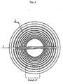
- the orientation of the fiber bundles in the moldings produced according to the invention may be random, ie randomly distributed. This is preferred when the body is exposed to approximately uniform loading in all roughness directions. For moldings which experience a particular load in a certain direction, however, a load-oriented orientation of the fiber bundles is desired. This can be achieved by simple measures when filling the fiber bundle containing molding compound in the pressing tool, for example by using a Be Heilllgitters. For brake discs, it is preferable to arrange the fiber bundles according to the tensile load occurring in the tangential direction. For this purpose, a He hypogalgitter is used, which contains a plurality of concentrically arranged rings.
- Each 50,000 nearly parallel single filaments carbon fiber strands are impregnated with a phenolic resin (Narsophen 1203 from Hexion), so that -ein- prepreg having a mass-based resin content of 35% and a basis weight of 320 g / m 2 is formed
- This prepreg is continuously compressed at a rate of 1 m / min at a pressure of 1 MPa (10 bar) on a belt press at a temperature of 180 ° C to a gel web with a thickness of 200 microns and at the same time hardened to a dimensionally stable Gelegebahn is obtained.
- the UD-Gelebahn is subsequently separated into individual strips with a width of 50 mm each. These are cut into segments (fiber bundles) having a length of 9.4 mm and a width of 1 mm as described above.
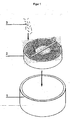
- FIG. 1 The filling process of the pressing tool is in FIG. 1 shown schematically.
- the pressing tool 1 whose cavity corresponds to the geometry of the brake disc to be produced, is filled with the molding compound containing the fiber bundles 3.
- a filling grid 2 is used, which comprises a plurality of concentric rings whose spacing is less than or equal to the length of the fiber bundles 3.
- FIG. 2 schematically shows how the filling grid 2 is arranged on the pressing tool 1.
- the filled press tool is exposed to a hot extrusion press for 30 minutes at a pressure of 4.0 N / mm 2 and a temperature of 160 ° C and then removed from the mold. During the pressing process, the phenolic resin cures. There is obtained a final body green body in the form of a brake disc.
- the green body is heated in a protective gas oven under a nitrogen atmosphere at a heating rate of 1 K / min to a temperature of 900 ° C.
- the phenolic resins are decomposed to a residue consisting essentially of carbon. This temperature is maintained for one hour. Thereafter, the carbonized molded body is cooled to room temperature.
- a carbon matrix is deposited by chemical vapor infiltration (CVI).
- CVI chemical vapor infiltration
- the CVI is carried out at 1100 ° C with methane as Carbon donor.
- methane as Carbon donor.
- carbon deposition the density of the carbonized molded article increases from 1.3 to 1.8 g / cm 3 .
- a coefficient of friction of ⁇ 0.5 to 0.6 was determined on the flywheel test bench.
- the strength of the brake disks determined in the bending test increases by 12 to 20% with respect to brake disks with a random arrangement of the fiber bundles.
Landscapes
- Chemical & Material Sciences (AREA)
- Engineering & Computer Science (AREA)
- General Engineering & Computer Science (AREA)
- Materials Engineering (AREA)
- Ceramic Engineering (AREA)
- Mechanical Engineering (AREA)
- Organic Chemistry (AREA)
- Chemical Kinetics & Catalysis (AREA)
- Manufacturing & Machinery (AREA)
- Composite Materials (AREA)
- Structural Engineering (AREA)
- General Chemical & Material Sciences (AREA)
- Metallurgy (AREA)
- Inorganic Chemistry (AREA)
- Ceramic Products (AREA)
- Braking Arrangements (AREA)
- Treatments For Attaching Organic Compounds To Fibrous Goods (AREA)
Priority Applications (6)
| Application Number | Priority Date | Filing Date | Title |
|---|---|---|---|
| EP06007572.8A EP1845075B1 (de) | 2006-04-11 | 2006-04-11 | Formkörper aus carbonfaserverstärktem Kohlenstoff und ein Verfahren zur deren Herstellung |
| CN2007100920051A CN101055008B (zh) | 2006-04-11 | 2007-04-04 | 由碳纤维增强的碳制备模制体的方法 |
| JP2007099426A JP5096031B2 (ja) | 2006-04-11 | 2007-04-05 | 炭素繊維強化炭素からの成形物体の製造 |
| US11/786,277 US20080176067A1 (en) | 2006-04-11 | 2007-04-11 | Process for producing shaped bodies of carbon fiber reinforced carbon and shaped body produced by the process |
| KR1020070035588A KR20070101177A (ko) | 2006-04-11 | 2007-04-11 | 탄소 섬유 강화된 탄소를 포함하는 성형체의 제조 |
| US15/278,056 US10336655B2 (en) | 2006-04-11 | 2016-09-28 | Process for producing shaped bodies of carbon fiber reinforced carbon |
Applications Claiming Priority (1)
| Application Number | Priority Date | Filing Date | Title |
|---|---|---|---|
| EP06007572.8A EP1845075B1 (de) | 2006-04-11 | 2006-04-11 | Formkörper aus carbonfaserverstärktem Kohlenstoff und ein Verfahren zur deren Herstellung |
Publications (2)
| Publication Number | Publication Date |
|---|---|
| EP1845075A1 EP1845075A1 (de) | 2007-10-17 |
| EP1845075B1 true EP1845075B1 (de) | 2016-04-06 |
Family
ID=36913096
Family Applications (1)
| Application Number | Title | Priority Date | Filing Date |
|---|---|---|---|
| EP06007572.8A Active EP1845075B1 (de) | 2006-04-11 | 2006-04-11 | Formkörper aus carbonfaserverstärktem Kohlenstoff und ein Verfahren zur deren Herstellung |
Country Status (5)
| Country | Link |
|---|---|
| US (2) | US20080176067A1 (enExample) |
| EP (1) | EP1845075B1 (enExample) |
| JP (1) | JP5096031B2 (enExample) |
| KR (1) | KR20070101177A (enExample) |
| CN (1) | CN101055008B (enExample) |
Families Citing this family (8)
| Publication number | Priority date | Publication date | Assignee | Title |
|---|---|---|---|---|
| KR101336101B1 (ko) * | 2010-11-29 | 2013-12-03 | 주식회사 데크 | 탄소-세라믹 브레이크 디스크 및 이를 만드는 방법 |
| US8597772B2 (en) * | 2011-09-20 | 2013-12-03 | Honeywell International Inc. | Corrugated carbon fiber preform |
| CN102492289B (zh) * | 2011-11-14 | 2013-08-28 | 丹阳丹金航空材料科技有限公司 | 一种碳纤维增强复合材料及其制备工艺 |
| EP2727896B1 (en) | 2012-11-02 | 2019-04-10 | Brembo SGL Carbon Ceramic Brakes GmbH | Process of manufacturing a brake disc assembly |
| CN105715719B (zh) * | 2016-03-21 | 2018-02-02 | 北京科技大学 | 一种高导热半金属刹车片 |
| US11655871B2 (en) * | 2020-03-13 | 2023-05-23 | Goodrich Corporation | Composites and methods of forming composites via pitch infiltration |
| US20250075759A1 (en) * | 2023-09-05 | 2025-03-06 | Goodrich Corporation | Ceramic particualte coating for wear improvement |
| CN118479885A (zh) * | 2024-03-29 | 2024-08-13 | 深圳市佰斯倍新材料科技有限公司 | 一种基体中含短切碳纤维的碳陶刹车盘及其制备方法 |
Family Cites Families (13)
| Publication number | Priority date | Publication date | Assignee | Title |
|---|---|---|---|---|
| GB1460876A (en) * | 1975-01-03 | 1977-01-06 | Coal Ind | Carbon artefacts |
| US4297307A (en) * | 1979-06-29 | 1981-10-27 | Union Carbide Corporation | Process for producing carbon-carbon fiber composites suitable for use as aircraft brake discs |
| FR2643656B1 (fr) * | 1989-02-27 | 1992-02-14 | Brochier Sa | Structure textile en forme de spirale, procede d'obtention et machine a tisser correspondante |
| DE69108776T2 (de) * | 1990-05-10 | 1995-08-24 | Lorraine Carbone | Reibelemente aus Kohlenstoff-Kohlenstoff-Verbundwerkstoff mit verschiedener Textur, Verfahren und Vorrichtungen zu ihrer Herstellung. |
| JPH05148062A (ja) * | 1991-11-25 | 1993-06-15 | Kawasaki Steel Corp | 炭素材料の製造方法 |
| US5437821A (en) * | 1992-09-30 | 1995-08-01 | The United States Of America As Represented By The Secretary Of The Navy | Process for making carbon-carbon composites by using acetylene terminated conjugated Schiff's base monomers |
| US5744075A (en) * | 1995-05-19 | 1998-04-28 | Martin Marietta Energy Systems, Inc. | Method for rapid fabrication of fiber preforms and structural composite materials |
| EP1124074B2 (en) * | 2000-02-09 | 2010-09-22 | Freni Brembo S.p.A. | A shaped composite material for breaking applications and a method for the preparation thereof |
| DE60029298T3 (de) * | 2000-02-09 | 2010-09-23 | Freni Brembo S.P.A., Curno | Bremsscheibe für eine Scheibenbremse |
| US6691393B2 (en) * | 2001-04-09 | 2004-02-17 | Honeywell International Inc. | Wear resistance in carbon fiber friction materials |
| DE10164226C5 (de) * | 2001-12-31 | 2011-04-14 | Audi Ag | Formkörper aus faserverstärkten keramischen Verbundwerkstoffen, Verfahren zu deren Herstellung und seine Verwendung |
| DE10341734A1 (de) * | 2003-09-08 | 2005-04-07 | Sgl Carbon Ag | Zylinderringförmige Körper aus mit Kurzfasern verstärktem keramischen Verbundmaterial |
| US20050074595A1 (en) * | 2003-10-03 | 2005-04-07 | Lam Robert C. | Friction material containing partially carbonized carbon fibers |
-
2006
- 2006-04-11 EP EP06007572.8A patent/EP1845075B1/de active Active
-
2007
- 2007-04-04 CN CN2007100920051A patent/CN101055008B/zh not_active Expired - Fee Related
- 2007-04-05 JP JP2007099426A patent/JP5096031B2/ja not_active Expired - Fee Related
- 2007-04-11 KR KR1020070035588A patent/KR20070101177A/ko not_active Ceased
- 2007-04-11 US US11/786,277 patent/US20080176067A1/en not_active Abandoned
-
2016
- 2016-09-28 US US15/278,056 patent/US10336655B2/en active Active
Also Published As
| Publication number | Publication date |
|---|---|
| JP2007277087A (ja) | 2007-10-25 |
| JP5096031B2 (ja) | 2012-12-12 |
| EP1845075A1 (de) | 2007-10-17 |
| CN101055008A (zh) | 2007-10-17 |
| US20080176067A1 (en) | 2008-07-24 |
| CN101055008B (zh) | 2011-06-01 |
| US20170015594A1 (en) | 2017-01-19 |
| US10336655B2 (en) | 2019-07-02 |
| KR20070101177A (ko) | 2007-10-16 |
Similar Documents
| Publication | Publication Date | Title |
|---|---|---|
| EP1054765B1 (de) | Verfahren zur herstellung eines faserverbundwerkstoffs | |
| EP0864548B1 (de) | Mit Graphitkurzfasern verstärkter Siliciumcarbidkörper | |
| DE60205733T2 (de) | Ringförmiger vorkörper für bremsen aus kohlenstofffasern und herstellungsverfahren | |
| DE102004009264B4 (de) | Herstellung eines Vorformlings durch Verstärken einer faserartigen Struktur und/oder Verbinden von faserartigen Strukturen untereinander und Anwendung bei der Herstellung von Teilen aus Verbundwerkstoff | |
| EP1511949B1 (de) | Nach tfp prozess hergestelltes tribologisches faserverbundbauteil | |
| EP1645671B2 (de) | Polymergebundene fasergelege | |
| EP1084997A2 (de) | Mit Faserbündeln verstärkter Verbundwerkstoff mit keramischen Matrix | |
| DE60029298T3 (de) | Bremsscheibe für eine Scheibenbremse | |
| DE10164226A1 (de) | Faserverstärkter keramischer Verbundwerkstoff | |
| DE19861035C2 (de) | Faserverbundwerkstoff und Verfahren zu dessen Herstellung | |
| DE102011081263A1 (de) | Verfestigte Faserbündel | |
| US10336655B2 (en) | Process for producing shaped bodies of carbon fiber reinforced carbon | |
| EP0636428A1 (de) | Verfahren zum Wiederverwerten von kohlenstoffaserhaltigen Verbundwerkstoffen | |
| US20090148699A1 (en) | Carbon fiber containing ceramic particles | |
| DE60010845T3 (de) | Geformtes Verbundmaterial für Bremsen und Verfahren zu seiner Herstellung | |
| EP1634860A2 (de) | Verfahren zur Herstellung eines Carbidkeramikmaterials, Carbidkeramikmaterial, Vorkörper für ein carbidkeramisches Bauteil und Verfahren zur Bereitstellung eines Ausgangsmaterials für einen Vorkörper für keramisches Material | |
| EP1845074B1 (de) | Verfahren zum Imprägnieren von Kurzfaserbündeln aus Carbonfasern | |
| DE102015221111A1 (de) | Carbonfaserverstärktes carbidkeramisches Verbundbauteil | |
| EP0976945B1 (de) | Verfahren zur Herstellung von Verstärkungsfasern enthaltenden Reibungskörper | |
| EP1876158B1 (de) | Verfahren zur Herstellung von Carbidkeramik-Bauteilen | |
| EP2058545B1 (de) | Verfahren zur Herstellung von Reibscheiben aus faserverstärkten keramischen Werkstoffen | |
| EP2053029B1 (de) | Verfahren zur Herstellung eines carbidkeramischen Bauteils | |
| DE10260923B4 (de) | Verfahren zur Herstellung von Hohlkörpern aus faserverstärkten keramischen Materialien, dadurch erhältliche Hohlkörper und deren Verwendung | |
| DE19815308C2 (de) | Verfahren zur Herstellung von Verstärkungsfasern oder Verstärkungsfaserbündeln, so hergestellte Fasern oder Bündel und deren Verwendung | |
| EP1988068B1 (de) | Verfahren zur herstellung von mit fasern verstärkten formkörpern |
Legal Events
| Date | Code | Title | Description |
|---|---|---|---|
| PUAI | Public reference made under article 153(3) epc to a published international application that has entered the european phase |
Free format text: ORIGINAL CODE: 0009012 |
|
| AK | Designated contracting states |
Kind code of ref document: A1 Designated state(s): AT BE BG CH CY CZ DE DK EE ES FI FR GB GR HU IE IS IT LI LT LU LV MC NL PL PT RO SE SI SK TR |
|
| AX | Request for extension of the european patent |
Extension state: AL BA HR MK YU |
|
| 17P | Request for examination filed |
Effective date: 20080417 |
|
| 17Q | First examination report despatched |
Effective date: 20080528 |
|
| AKX | Designation fees paid |
Designated state(s): AT BE BG CH CY CZ DE DK EE ES FI FR GB GR HU IE IS IT LI LT LU LV MC NL PL PT RO SE SI SK TR |
|
| RAP1 | Party data changed (applicant data changed or rights of an application transferred) |
Owner name: SGL CARBON SE |
|
| RAP1 | Party data changed (applicant data changed or rights of an application transferred) |
Owner name: SGL CARBON SE |
|
| GRAP | Despatch of communication of intention to grant a patent |
Free format text: ORIGINAL CODE: EPIDOSNIGR1 |
|
| INTG | Intention to grant announced |
Effective date: 20151023 |
|
| GRAS | Grant fee paid |
Free format text: ORIGINAL CODE: EPIDOSNIGR3 |
|
| GRAA | (expected) grant |
Free format text: ORIGINAL CODE: 0009210 |
|
| AK | Designated contracting states |
Kind code of ref document: B1 Designated state(s): AT BE BG CH CY CZ DE DK EE ES FI FR GB GR HU IE IS IT LI LT LU LV MC NL PL PT RO SE SI SK TR |
|
| REG | Reference to a national code |
Ref country code: GB Ref legal event code: FG4D Free format text: NOT ENGLISH |
|
| REG | Reference to a national code |
Ref country code: AT Ref legal event code: REF Ref document number: 787630 Country of ref document: AT Kind code of ref document: T Effective date: 20160415 Ref country code: CH Ref legal event code: EP |
|
| REG | Reference to a national code |
Ref country code: IE Ref legal event code: FG4D Free format text: LANGUAGE OF EP DOCUMENT: GERMAN |
|
| REG | Reference to a national code |
Ref country code: DE Ref legal event code: R096 Ref document number: 502006014855 Country of ref document: DE |
|
| REG | Reference to a national code |
Ref country code: FR Ref legal event code: PLFP Year of fee payment: 11 |
|
| REG | Reference to a national code |
Ref country code: LT Ref legal event code: MG4D Ref country code: NL Ref legal event code: MP Effective date: 20160406 |
|
| PG25 | Lapsed in a contracting state [announced via postgrant information from national office to epo] |
Ref country code: BE Free format text: LAPSE BECAUSE OF NON-PAYMENT OF DUE FEES Effective date: 20160430 |
|
| PG25 | Lapsed in a contracting state [announced via postgrant information from national office to epo] |
Ref country code: NL Free format text: LAPSE BECAUSE OF FAILURE TO SUBMIT A TRANSLATION OF THE DESCRIPTION OR TO PAY THE FEE WITHIN THE PRESCRIBED TIME-LIMIT Effective date: 20160406 |
|
| PG25 | Lapsed in a contracting state [announced via postgrant information from national office to epo] |
Ref country code: IS Free format text: LAPSE BECAUSE OF FAILURE TO SUBMIT A TRANSLATION OF THE DESCRIPTION OR TO PAY THE FEE WITHIN THE PRESCRIBED TIME-LIMIT Effective date: 20160806 Ref country code: FI Free format text: LAPSE BECAUSE OF FAILURE TO SUBMIT A TRANSLATION OF THE DESCRIPTION OR TO PAY THE FEE WITHIN THE PRESCRIBED TIME-LIMIT Effective date: 20160406 Ref country code: LT Free format text: LAPSE BECAUSE OF FAILURE TO SUBMIT A TRANSLATION OF THE DESCRIPTION OR TO PAY THE FEE WITHIN THE PRESCRIBED TIME-LIMIT Effective date: 20160406 Ref country code: PL Free format text: LAPSE BECAUSE OF FAILURE TO SUBMIT A TRANSLATION OF THE DESCRIPTION OR TO PAY THE FEE WITHIN THE PRESCRIBED TIME-LIMIT Effective date: 20160406 |
|
| PG25 | Lapsed in a contracting state [announced via postgrant information from national office to epo] |
Ref country code: GR Free format text: LAPSE BECAUSE OF FAILURE TO SUBMIT A TRANSLATION OF THE DESCRIPTION OR TO PAY THE FEE WITHIN THE PRESCRIBED TIME-LIMIT Effective date: 20160707 Ref country code: LV Free format text: LAPSE BECAUSE OF FAILURE TO SUBMIT A TRANSLATION OF THE DESCRIPTION OR TO PAY THE FEE WITHIN THE PRESCRIBED TIME-LIMIT Effective date: 20160406 Ref country code: SE Free format text: LAPSE BECAUSE OF FAILURE TO SUBMIT A TRANSLATION OF THE DESCRIPTION OR TO PAY THE FEE WITHIN THE PRESCRIBED TIME-LIMIT Effective date: 20160406 Ref country code: ES Free format text: LAPSE BECAUSE OF FAILURE TO SUBMIT A TRANSLATION OF THE DESCRIPTION OR TO PAY THE FEE WITHIN THE PRESCRIBED TIME-LIMIT Effective date: 20160406 Ref country code: PT Free format text: LAPSE BECAUSE OF FAILURE TO SUBMIT A TRANSLATION OF THE DESCRIPTION OR TO PAY THE FEE WITHIN THE PRESCRIBED TIME-LIMIT Effective date: 20160808 |
|
| REG | Reference to a national code |
Ref country code: CH Ref legal event code: PL |
|
| REG | Reference to a national code |
Ref country code: DE Ref legal event code: R097 Ref document number: 502006014855 Country of ref document: DE |
|
| REG | Reference to a national code |
Ref country code: IE Ref legal event code: MM4A |
|
| PG25 | Lapsed in a contracting state [announced via postgrant information from national office to epo] |
Ref country code: LI Free format text: LAPSE BECAUSE OF NON-PAYMENT OF DUE FEES Effective date: 20160430 Ref country code: DK Free format text: LAPSE BECAUSE OF FAILURE TO SUBMIT A TRANSLATION OF THE DESCRIPTION OR TO PAY THE FEE WITHIN THE PRESCRIBED TIME-LIMIT Effective date: 20160406 Ref country code: SK Free format text: LAPSE BECAUSE OF FAILURE TO SUBMIT A TRANSLATION OF THE DESCRIPTION OR TO PAY THE FEE WITHIN THE PRESCRIBED TIME-LIMIT Effective date: 20160406 Ref country code: MC Free format text: LAPSE BECAUSE OF FAILURE TO SUBMIT A TRANSLATION OF THE DESCRIPTION OR TO PAY THE FEE WITHIN THE PRESCRIBED TIME-LIMIT Effective date: 20160406 Ref country code: CZ Free format text: LAPSE BECAUSE OF FAILURE TO SUBMIT A TRANSLATION OF THE DESCRIPTION OR TO PAY THE FEE WITHIN THE PRESCRIBED TIME-LIMIT Effective date: 20160406 Ref country code: RO Free format text: LAPSE BECAUSE OF FAILURE TO SUBMIT A TRANSLATION OF THE DESCRIPTION OR TO PAY THE FEE WITHIN THE PRESCRIBED TIME-LIMIT Effective date: 20160406 Ref country code: EE Free format text: LAPSE BECAUSE OF FAILURE TO SUBMIT A TRANSLATION OF THE DESCRIPTION OR TO PAY THE FEE WITHIN THE PRESCRIBED TIME-LIMIT Effective date: 20160406 Ref country code: CH Free format text: LAPSE BECAUSE OF NON-PAYMENT OF DUE FEES Effective date: 20160430 |
|
| PLBE | No opposition filed within time limit |
Free format text: ORIGINAL CODE: 0009261 |
|
| STAA | Information on the status of an ep patent application or granted ep patent |
Free format text: STATUS: NO OPPOSITION FILED WITHIN TIME LIMIT |
|
| 26N | No opposition filed |
Effective date: 20170110 |
|
| REG | Reference to a national code |
Ref country code: FR Ref legal event code: PLFP Year of fee payment: 12 |
|
| PG25 | Lapsed in a contracting state [announced via postgrant information from national office to epo] |
Ref country code: IE Free format text: LAPSE BECAUSE OF NON-PAYMENT OF DUE FEES Effective date: 20160411 Ref country code: SI Free format text: LAPSE BECAUSE OF FAILURE TO SUBMIT A TRANSLATION OF THE DESCRIPTION OR TO PAY THE FEE WITHIN THE PRESCRIBED TIME-LIMIT Effective date: 20160406 |
|
| REG | Reference to a national code |
Ref country code: AT Ref legal event code: MM01 Ref document number: 787630 Country of ref document: AT Kind code of ref document: T Effective date: 20160411 |
|
| PG25 | Lapsed in a contracting state [announced via postgrant information from national office to epo] |
Ref country code: AT Free format text: LAPSE BECAUSE OF NON-PAYMENT OF DUE FEES Effective date: 20160411 |
|
| REG | Reference to a national code |
Ref country code: FR Ref legal event code: PLFP Year of fee payment: 13 |
|
| PG25 | Lapsed in a contracting state [announced via postgrant information from national office to epo] |
Ref country code: CY Free format text: LAPSE BECAUSE OF FAILURE TO SUBMIT A TRANSLATION OF THE DESCRIPTION OR TO PAY THE FEE WITHIN THE PRESCRIBED TIME-LIMIT Effective date: 20160406 Ref country code: HU Free format text: LAPSE BECAUSE OF FAILURE TO SUBMIT A TRANSLATION OF THE DESCRIPTION OR TO PAY THE FEE WITHIN THE PRESCRIBED TIME-LIMIT; INVALID AB INITIO Effective date: 20060411 |
|
| PG25 | Lapsed in a contracting state [announced via postgrant information from national office to epo] |
Ref country code: TR Free format text: LAPSE BECAUSE OF FAILURE TO SUBMIT A TRANSLATION OF THE DESCRIPTION OR TO PAY THE FEE WITHIN THE PRESCRIBED TIME-LIMIT Effective date: 20160406 Ref country code: LU Free format text: LAPSE BECAUSE OF NON-PAYMENT OF DUE FEES Effective date: 20160411 |
|
| PG25 | Lapsed in a contracting state [announced via postgrant information from national office to epo] |
Ref country code: BG Free format text: LAPSE BECAUSE OF FAILURE TO SUBMIT A TRANSLATION OF THE DESCRIPTION OR TO PAY THE FEE WITHIN THE PRESCRIBED TIME-LIMIT Effective date: 20160406 |
|
| PGFP | Annual fee paid to national office [announced via postgrant information from national office to epo] |
Ref country code: FR Payment date: 20230425 Year of fee payment: 18 Ref country code: DE Payment date: 20230427 Year of fee payment: 18 |
|
| P01 | Opt-out of the competence of the unified patent court (upc) registered |
Effective date: 20230810 |
|
| REG | Reference to a national code |
Ref country code: DE Ref legal event code: R119 Ref document number: 502006014855 Country of ref document: DE |
|
| PG25 | Lapsed in a contracting state [announced via postgrant information from national office to epo] |
Ref country code: DE Free format text: LAPSE BECAUSE OF NON-PAYMENT OF DUE FEES Effective date: 20241105 |
|
| PG25 | Lapsed in a contracting state [announced via postgrant information from national office to epo] |
Ref country code: FR Free format text: LAPSE BECAUSE OF NON-PAYMENT OF DUE FEES Effective date: 20240430 |
|
| PG25 | Lapsed in a contracting state [announced via postgrant information from national office to epo] |
Ref country code: FR Free format text: LAPSE BECAUSE OF NON-PAYMENT OF DUE FEES Effective date: 20240430 Ref country code: DE Free format text: LAPSE BECAUSE OF NON-PAYMENT OF DUE FEES Effective date: 20241105 |
|
| PGFP | Annual fee paid to national office [announced via postgrant information from national office to epo] |
Ref country code: GB Payment date: 20250428 Year of fee payment: 20 |
|
| PGFP | Annual fee paid to national office [announced via postgrant information from national office to epo] |
Ref country code: IT Payment date: 20250422 Year of fee payment: 20 |