EP1844637B1 - Dispositif pour refroidir des unites modulaires electroniques dans des armoires d'equipements et de reseau - Google Patents
Dispositif pour refroidir des unites modulaires electroniques dans des armoires d'equipements et de reseau Download PDFInfo
- Publication number
- EP1844637B1 EP1844637B1 EP05804961A EP05804961A EP1844637B1 EP 1844637 B1 EP1844637 B1 EP 1844637B1 EP 05804961 A EP05804961 A EP 05804961A EP 05804961 A EP05804961 A EP 05804961A EP 1844637 B1 EP1844637 B1 EP 1844637B1
- Authority
- EP
- European Patent Office
- Prior art keywords
- heat exchanger
- air
- cabinet
- arrangement according
- fan door
- Prior art date
- Legal status (The legal status is an assumption and is not a legal conclusion. Google has not performed a legal analysis and makes no representation as to the accuracy of the status listed.)
- Not-in-force
Links
Images


Classifications
-
- G—PHYSICS
- G06—COMPUTING; CALCULATING OR COUNTING
- G06F—ELECTRIC DIGITAL DATA PROCESSING
- G06F1/00—Details not covered by groups G06F3/00 - G06F13/00 and G06F21/00
- G06F1/16—Constructional details or arrangements
- G06F1/20—Cooling means
-
- H—ELECTRICITY
- H05—ELECTRIC TECHNIQUES NOT OTHERWISE PROVIDED FOR
- H05K—PRINTED CIRCUITS; CASINGS OR CONSTRUCTIONAL DETAILS OF ELECTRIC APPARATUS; MANUFACTURE OF ASSEMBLAGES OF ELECTRICAL COMPONENTS
- H05K7/00—Constructional details common to different types of electric apparatus
- H05K7/20—Modifications to facilitate cooling, ventilating, or heating
- H05K7/20709—Modifications to facilitate cooling, ventilating, or heating for server racks or cabinets; for data centers, e.g. 19-inch computer racks
- H05K7/20763—Liquid cooling without phase change
- H05K7/20781—Liquid cooling without phase change within cabinets for removing heat from server blades
Definitions
- the invention relates to an arrangement for cooling electronic module units in device and network cabinets, in particular server cabinets., In a room, according to the preamble of claim 1.
- Out DE 195 15 121 C2 is a housing structure for outdoor deployable electrical and / or electronic devices known.
- the outdoor enclosure construction consists of an inner cabinet and a spaced outer cabinet.
- a cooling-air fan arranged on the bottom side in the outer cabinet sucks in a cooling-air flow from the environment into the outer cabinet, which has upper outlet openings.
- An air heat exchanger in the inner cabinet which is supplied with the cooling air from the outer cabinet, and circulating fans provide a circulated inner air flow.
- the electrical and electronic devices are arranged on heat sinks, which are held in wall openings of the inner cabinet and communicate with the interior of the inner cabinet.
- a control cabinet is described with a designed as a rear wall cooling device having an air-water heat exchanger and blower.
- the hot air partial flows from the interior of the cabinet are sucked and returned as cooled air via a arranged under the interior ventilation duct and an air-storage chamber on the front side of the interior of the cabinet.
- a modular control cabinet system DE 198 25 602 C2 is provided with a set of doors, each having at least one fan, interchangeable and for receiving a cooling module, such as a compressor-cooling device, an air-to-air heat exchanger or an air-water heat exchanger, are formed according to the requirements.
- a cooling module such as a compressor-cooling device, an air-to-air heat exchanger or an air-water heat exchanger
- U1 is a device and network cabinet, in particular server cabinet, with arranged in an interior electronic module units, especially servers, and arranged in the lower cabinet area air-water heat exchanger known, which is connected to the cold water supply of the building.
- the deflection of the exhaust air flow takes place with the aid of fans in the upper region of the rear door, wherein advantageously in the rear door, a right and a left descending exhaust duct is provided, through which the exhaust air is supplied to the air-water heat exchanger.
- US Pat. No. 6,819,563 B1 is a set up in a room equipment cabinet for superimposed and provided with a fan electronic devices or components known.
- This indoor equipment cabinet is supplied with conditioned room air for cooling the electronic components.
- This room air is cooled by means of an arranged in the equipment cabinet inlet heat exchanger, which is acted upon with cooling water, then passes into the stacked electronic devices and is returned as heated exhaust air in the room.
- an output heat exchanger can be arranged in the equipment cabinet, which cools the heated exhaust air before it is discharged into the ambient air.
- a cooling system for equipment and network cabinets is known, which is to dissipate the heat loss of powerful, tightly packed electronic module units in a variety of juxtaposed cabinets in a space flexible and effective.
- the cooling system is to complement the air conditioning and make it more cost-effective by the exhaust air heated in a closet supplied by fans to an air-fluid heat exchanger, cooled to room temperature and released into the ambient air.
- the fans and the heat exchanger are housed in an additional housing, which is attached to the back of the cabinet.
- the exhaust air from the cabinet passes through an opening in the cabinet rear wall or cabinet door and a complementary opening in the adjacent heat exchanger fan housing in the interior of this housing and is guided over the near the housing opening arranged air-fluid heat exchanger by means of the downstream fans and discharged via the outer wall of the housing to the environment.
- the connecting hoses which extend from bottom-side connection points to the connections on each RackCooler, must be relatively flexible due to the arrangement of the RackCooler on the rear doors and be able to follow the pivoting movement of the doors. This has the disadvantages that the connecting hoses only have a lack of mechanical stability and robustness and also not the required gas tightness, so that it may come to a corrosion of the tubes of the heat exchanger due to gas diffusion.
- the invention has for its object to provide an arrangement for cooling of electronic module units in equipment and network cabinets, especially rows of cabinets in a room, which with a simple design and stable training the required accessibility to the receiving space and an extremely efficient dissipation of the heat loss ensured electronic module units.
- An air-fluid heat exchanger is understood to mean an air-liquid heat exchanger.
- an arrangement with an air-fluid heat exchanger in particular an air-water heat exchanger, which is connected to the cold water supply of the building and dissipates the heat loss outside the cupboard storage room, from a fan arrangement, which the air-fluid heat exchanger the exhaust air of the electronic module units of a cabinet supplies, structurally separated.
- the fans are integrated in a door and preferably in a rear door of a cabinet.
- Such a trained fan door preferably extends over the entire height of the cabinet, at least over the height of the receiving space for electronic module units, such as servers, and allows access to the server from the back.
- Such back access is particularly advantageous in the arrangement of blade servers, which are usually not taken forward, but extendable to the rear in a stacking arrangement.
- the air-fluid heat exchanger is structurally separate from the fan door at the back of the cabinet under cover of a residual area of the cabinet back, ie, at least the area which is not covered by the fan door, fixedly arranged.
- the advantage of a rigid, suitably dismountable arrangement of the air-fluid heat exchanger longitudinally and preferably vertically adjacent to the fan door and adjacent thereto and preferably connected by hinges, is that rigid pipes for the connection of the laid under the floor slab pipe system for the Coolant can be arranged with each air-fluid heat exchanger of a cabinet. It is no longer necessary to use flexible connecting hoses because the air-fluid heat exchanger is fixed firmly and not pivotably on the back of the cabinet.
- the rigid tubes can be made of a gas-diffusion-proof material, which are known in principle from the heating technology. By excluding gas diffusion in the region of the connecting pipes, there is no or only a considerably reduced risk of corrosion in the region of the heat exchanger. This is associated with a beneficial longer life.
- the fan door and the longitudinally adjacent air-fluid heat exchanger be designed as a retrofittable unit and can replace a conventional cabinet rear door, if there is a need for a much more efficient dissipation of the heat loss.
- the possible retrofitting also opens up the advantageous possibility of providing high-performance cooling with relatively low investment and operating costs, in particular in commercial data centers with up to 100 cabinets, individual cabinets with the fan door according to the invention and the adjoining fixed air-fluid heat exchanger , As a result, the equipment of the cabinets and the occupancy of the room can be optimized with such cabinets while reducing the cost of air conditioning.
- the fan door fans preferably radial fans, evenly spaced and in particular arranged one above the other and directly or indirectly attached to an inside and outside of the cabinet-like fan door.
- Complementary openings are formed on the inside of the fan door for removing the exhaust air from the receiving space of the cabinet, and after a deflection of about 90 °, the air passes through an at least partially air-permeable connection side of the fan door in the adjacent air-fluid heat exchanger.
- An inlet side of the heat exchanger housing may expediently be designed to be permeable to air or perforated in the same way as the connection side of the fan door, and a parallel air-permeable outlet side of the heat exchanger housing allows the exit of the cooled air into the cabinet environment.
- the supply of cooling air from the environment of the cabinets in the receiving space is usually in the range of the front door of the cabinet, and arranged in particular in a stack arrangement electronic module units may each have a fan in their cases.
- the fan door is usefully articulated by hinges on the heat exchanger and can be pivoted from a closed position to an open position. Particularly advantageous is a 180 ° opening position, as this allows an advantageous access to the electronic module units and the wiring area at the back of the cabinet.
- corresponding seals are located in the area of the cabinet rear and / or the adjacent fan door and between the fan door and the heat exchanger housing to be in the operative position, i. with closed fan door to ensure efficient discharge of the heated exhaust air, their cooling and delivery to the ambient air.
- the fan door and / or the air-fluid heat exchanger for different widths cabinets and for different widths back access areas can be trained.
- an access area of about 665 mm width can be achieved by a laterally projecting arrangement of the heat exchanger. If the outside of the fan door is slanted adjacent to the closing side of the fan door, a favorable pivotal movement of the rear fan door of the adjacent cabinet is made possible.
- a further advantage is that for a cabinet which has, for example, a width of 600 mm and which is preferably provided for blade server, the same heat exchanger unit can be attached to the back of the cabinet and in particular aligned with a side wall.
- the fan door then has a smaller width, for example of about 350 to 400 mm, which, however, sufficient for an actuation of the blade server from the back.
- the fan door can be hinged to the heat exchanger via hinges on the outer wall and pivoted by a vertical pivot axis through 180 ° in an open position.
- the superimposed fans are mounted in the region of, for example, nozzle-like insertion openings on the inside of the door and preferably extend to the outer wall of the fan door, wherein here a spacer can be provided.
- the closing device of the fan door is suitably adapted to the door configuration and provided on the heat exchanger side opposite closing side of the fan door.
- the fan door can be articulated on its side opposite the heat exchanger on the cabinet rear wall. The closing side of the door would then be on the heat exchanger side.
- the advantages of such training are that the fan door does not need to be carried by the heat exchanger unit and the loads are distributed symmetrically on the cabinet to be retrofitted. It can be further expected that the seal at the joint between the fan door and the heat exchanger module is better manageable by the tightness of a declining bias of the seal is not dependent on the rotation angle and also the contact pressure can be influenced by the closing device. Furthermore, it is advantageous that in such a structural design of the free flow cross-section between the fan door and the heat exchanger unit can be made larger, which is associated with lower pressure losses.
- the hinge of the fan door may be disposed on an additional structure such that the pivot axis is spaced from the rear of the cabinet.
- the heat exchanger is arranged rigidly, but its housing, at least partially, is designed to be pivotable.
- the heat exchanger module can be provided with a heat exchanger door, which is articulated on a vertical pivot axis and allows access to the heat exchanger.
- the dividing plane between the fan door and the heat exchanger door is determined by the arrangement and space requirements of the fans and the heat exchanger.
- a rigid arrangement of at least one heat exchanger and a pivotable fan door can also be achieved in that the cabinet rear has two door halves and fans and a heat exchanger are located in each door half.
- Each heat exchanger is arranged rigidly according to the invention and each door or half-door with the fans, for example two fans, is mounted about an axis, e.g. in the area of the heat exchanger, pivotally hinged.
- This design variant also allows good access to the cabinet. Furthermore, a redundancy is given by the parting plane between the door halves is free, so that the fan can act on both heat exchangers. A uniform heat dissipation is achieved at the rear of the arranged electronic module units with the doors open.
- the at least one heat exchanger and the fans can be arranged in a door leaf, which covers substantially the entire rear side of the cabinet.
- the heat exchanger is rigidly mounted and the fan door is pivotally mounted about a longitudinal axis.
- the cooling arrangement according to the invention is preferably provided for an air duct, in which exhaust air passes from the receiving space of the cabinet in the fan door and then in the fixed heat exchanger. It is within the scope of the invention to first guide the exhaust air flow from the cabinet through the heat exchanger and then deliver it to the environment via the fan door.
- the main advantages of the cooling arrangement according to the invention are the retrofitting and the use of gas-tight and rigid connecting tubes for the cooling medium made possible by the rigid attachment of the heat exchanger unit.
- the interface to different cabinet designs can be rigid, for example by means of screw, and required for the pivotal movement of the movable part, in particular the fan door hinges, pivot bearings can be used for all types of cabinets and sizes are executed uniformly. This considerably simplifies the retrofitting of existing device or network cabinets.
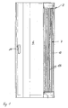
- a cabinet 2 in particular a server cabinet, shown with the cooling arrangement according to the invention on the back of the cabinet 2.
- a fan door 6 and an air-fluid heat exchanger 7 are arranged in the region of the back of the cabinet, which adjacent to each other and across the entire cabinet height, replacing a conventional back wall or rear door.
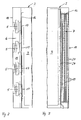
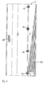
- the fan door 6 has in this embodiment, four superimposed fans 5 (see Fig. 2 ), which extend from an inner side 16 to an outer side 18 of the fan door 6 and suck exhaust air 10 from the receiving space 3 of the cabinet 2 via openings 17 in the inner side 16 and undergo an approximately 90 ° deflection (see also Fig. 4 ).
- the exhaust air 10 thereby passes into an exhaust air space 15 of the fan door 6, which is formed by the inner and outer sides 16, 18 and by a closing side 19 and a connecting side 20.
- a closing device 29 is provided, with which the fan door 6 in the in Fig. 4 shown operating position can be closed.
- the receiving space 15 of the fan door 6 is a sealed and at least partially air-permeable or perforated connecting side 20 with the air-fluid heat exchanger 7 in combination, wherein an air-permeable or perforated formed inlet side 21 of a heat exchanger housing 11 immediately adjacent to the connecting side 20 of the fan door 6 (see Fig. 4 ).
- the reaching into the heat exchanger 7 exhaust air 10 is cooled and discharged via an outlet side 22 which is parallel to the inlet side 21, as cooled exhaust air 30 in the ambient air of the installation space of the cabinets 2, preferably at ambient temperature.
- the air-fluid heat exchanger 7, which is a finned heat exchanger in this embodiment, and a tube-finned pack 12 of vertically aligned tubes 13, such as copper tubes and cooling fins, allows by connecting to the cooling water supply to the building a discharge of Heat loss to the outside of the cabinet receiving space.
- the cupboard of Fig. 1 to 5 has a width of about 750 mm, and the fan door 6 is provided with a chamfer 27 between the shutter 29 and the fans 5.
- This bevel is for a generous opening position (see Fig. 5 ) with access via an access area 8 advantageous.
- the relatively wide access area 8 is also achieved by a projecting arrangement of the air-fluid heat exchanger 7 (see Fig. 4 and 5 ).
- An adjacent cabinet is then spaced appropriately, and the beveled configuration of the fan door 6 allows access also to an adjacent cabinet, even if the fan doors 6 of both cabinets are in accordance with Fig. 5 are open.
- the protruding air-fluid heat exchanger 7 covers only a relatively narrow residual area 9 of the back of the cabinet 2.
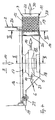
- the substantially identically formed air-fluid heat exchanger 7 is arranged flush with a side wall 26 of the cabinet 2 (see FIGS. 7 and 8 ).
- the heat exchanger 7 thus covers a wider residual area 9 of the back of the cabinet 2, and an access area 8, which is closed by a fan door 6 in the closed position, is narrower.
- this access area 8 allows the extraction of the electronic module units with the fan door 6 open according to Fig. 8 especially if it is a blade server (not shown).
- the Fig. 6 to 8 four fans 5 are arranged one above the other and suck the exhaust air 10 from the receiving space 3 in the door exhaust air space 15. After an approximately 90 ° deflection, the exhaust air 10 enters the Heat exchanger 7 and is discharged after cooling by means guided in the tubes 13 cooling liquid, in particular cooling water, via an outlet side 22 to the environment.
- the cooling arrangement which can be produced as a modular unit from a pivotable fan door 6 and a fixed heat exchanger 7 can replace a rear or rear door of a cabinet.
- the fan door 6 of the Fig. 6 to 8 which narrower than the Fig. 1 to 5 is, has a correspondingly adapted locking device 29 and can also about a vertical pivot axis 25 in a pivoted by 180 ° open position ( Fig. 8 ) to be brought.
- Fig. 9 to 13 show alternative embodiments for the arrangement of the retrofittable cooling arrangement.
- Fig. 9 is the fan door 6 unlike the Fig. 6 to 8 not hinged to the air-fluid heat exchanger 7 and to the heat exchanger housing 11, but on the back of the cabinet 2.
- the fan door 6 and the air-fluid heat exchanger 7 extend over the back of the cabinet 2, and the connecting side 20 of the fan door 6 is formed chamfered complementary to the inlet side 21 of the heat exchanger housing 11, thereby increasing the cross section for the air passage becomes.
- Fig. 10 shows a fan door 6, which is hinged to the air-fluid heat exchanger 7 opposite side.
- the pivot axis 25 is not arranged directly on the cabinet 2 or in the region of a side wall 28 of the cabinet 2, but is located on an auxiliary structure 32, for example, the side wall 28, and thus at a distance from the back of the cabinet. Due to the resulting larger opening angle better accessibility is given to the cabinet.
- Fig. 11 are the fan door 6 to the outside arranged pivot axis 25 and the heat exchanger housing 11 to the opposite vertical pivot axis 35 pivoted outwardly, so that the access width is almost unlimited.
- a corresponding seal is provided which can be advantageously supported by the locking device (not shown) to be arranged here.
- Fig. 12 a development is shown in which the inventive arrangement of fans and rigidly arranged heat exchanger (not shown) is realized in each case in a left door 40 and a right door 41, which, for example, as shown, may be formed as door halves.
- Each heat exchanger, the exhaust air from the cabinet 2 by means of fans (not shown) in each door 40, 41 are supplied, whereby a particularly uniform heat dissipation is achieved.
- a door 44 is provided at the rear of the cabinet 2.
- a heat exchanger (not shown) is rigidly housed, and with the door 44, only the fans arranged therein are pivoted.
Landscapes
- Engineering & Computer Science (AREA)
- Theoretical Computer Science (AREA)
- General Engineering & Computer Science (AREA)
- Physics & Mathematics (AREA)
- Human Computer Interaction (AREA)
- Microelectronics & Electronic Packaging (AREA)
- Thermal Sciences (AREA)
- General Physics & Mathematics (AREA)
- Computer Hardware Design (AREA)
- Cooling Or The Like Of Electrical Apparatus (AREA)
- Heat-Exchange Devices With Radiators And Conduit Assemblies (AREA)
- Coupling Device And Connection With Printed Circuit (AREA)
- Cooling Or The Like Of Semiconductors Or Solid State Devices (AREA)
Claims (23)
- Arrangement pour refroidir des unites modulaires électroniques dans des armoires d'equipments et des armoires de réseaux, notamment des armoires de serveurs dans une salle d'installation,
comportant une alimentation côté frontal d'air de refroidissement à partir de l'environnement de l'armoire (2), un échangeur de chaleur air/liquide (7) et des ventilateurs (5) installés dans la région du côté arrière de l'armoire (2) pour évacuer la chaleur dégagée par les unites modulaires électroniques et aspirant l'air d'évacuation (10) chargé de chaleur des unites modulaires électroniques de l'armoire (2) et avant d'évacuer dans l'air d'environnement de l'armoire (2), cet air est conduit dans l'échangeur de chaleur air/liquide (7) pour le réchauffer,
caractérisé en ce que
les ventilateurs (5) sont intégrés dans une porte et on forme une porte à ventilateurs (6) qui en position de fermeture, couvre une zone d'accès (8) du côté arrière de l'armoire (2) et
l'échangeur de chaleur air/liquide (7) est installé le long du grand côté de la porte à ventilateurs (6), de façon adjacente et en couvrant la plage résiduelle (9) du côté arrière de l'armoire (2). - Arrangement selon la revendication 1,
caractérisé en ce que
les ventilateurs (5) sont des ventilateurs radiaux, installés dans la porte à ventilateurs (6) et
l'air d'évacuation (10) alimente l'échangeur de chaleur air/liquide (7) adjacent à la porte à ventilateurs (6), pour l'air d'évacuation (10) dévié de 90° à partir de l'armoire (2). - Arrangement selon la revendication 1 ou 2,
caractérisé en ce que
la porte à ventilateurs (6) est articulée sur l'échangeur de chaleur air/liquide (7) et elle est basculée à partir d'une position de fermeture jusqu'à une position d'ouverture à 180°. - Arrangement selon l'une des revendications précédentes,
caractérisé en ce que
le liquide de refroidissement de l'échangeur air/liquide (7) évacue la chaleur dégagée reçue à l'extérieur de la salle d'installation des armoires. - Arrangement selon l'une des revendications précédentes,
caractérisé en ce que
l'échangeur de chaleur air/liquide (7) est un échangeur de chaleur air-eau. - Arrangement selon l'une des revendications précédentes,
caractérisé en ce que
l'échangeur de chaleur air/liquide (7) comporte un paquet de tubes et de lamelles (12) avec des tubes (13) dirigés verticalement pour le liquide de refroidissement, notamment pour l'eau de refroidissement d'une alimentation en eau froide de l'immeuble, dans un boîtier d'échangeur de chaleur (11). - Arrangement selon l'une des revendications précédentes,
caractérisé en ce que
la porte à ventilateurs (6) est en forme de caisson avec un côté intérieur (16) muni d'ouvertures (17) pour l'air d'évacuation (10) aspiré de l'armoire (2), un côté extérieur (18) qui est parallèle au côté intérieur (16) au moins dans la région des ventilateurs (5), un côté de fermeture (19) est parallèle à celui-ci, un côté de liaison (20) qui est adjacent au côté entrée (21) du boîtier (11) de l'échangeur de chaleur et est perforé au moins par zones comme celui-ci. - Arrangement selon l'une des revendications précédentes,
caractérisé en ce que
le boîtier d'échangeur de chaleur (11) comporte un côté de sortie (22) en regard du côté d'entrée (21) par lequel sort l'air d'évacuation (30) refroidi sensiblement à la température ambiante dans l'échangeur de chaleur air/liquide (7). - Arrangement selon l'une des revendications précédentes,
caractérisé en ce que
la porte à ventilateurs (6) est réalisée pour des armoires (2) de largeurs différentes et/ou des zones d'accès (8) côté arrière de largeurs différentes. - Arrangement selon l'une des revendications précédentes,
caractérisé en ce que
l'échangeur de chaleur air/liquide (7) est fixé de manière démontable dans la zone du côté arrière de l'armoire (2). - Arrangement selon l'une des revendications précédentes,
caractérisé en ce que
l'échangeur de chaleur air/liquide (7) est installé de façon alignée sur une paroi latérale (26) de l'armoire (2) ou en dépassant la paroi latérale (26) de l'armoire (2). - Arrangement selon l'une des revendications précédentes,
caractérisé en ce que
la porte à ventilateurs (6) est montée pivotante à l'aide de charnières (14) fixées sur le côté extérieur (18) de la porte à ventilateurs (6) et une paroi extérieure (23) du boîtier d'échangeur de chaleur (11) pour être pivotée autour d'un axe vertical (25). - Arrangement selon l'une des revendications précédentes,
caractérisé en ce que
le paquet de lamelles et de tubes (12) de l'échangeur de chaleur air/liquide (7) est relié par des tuyaux de liaison en une matière étanche à la diffusion gazeuse, avec l'alimentation en eau froide de l'immeuble. - Arrangement selon l'une des revendications précédentes,
caractérisé en ce que
la porte à ventilateurs (6) comporte plusieurs ventilateurs (5) superposés et/ou juxtaposés et fixés sur le côté intérieur et le côté extérieur (16, 18). - Arrangement selon l'une des revendications précédentes,
caractérisé en ce que
l'échangeur de chaleur air/liquide (7), comme la porte à ventilateurs (6), occupe la hauteur de l'armoire (2), au moins la hauteur du volume de réception (3) de celle-ci. - Arrangement selon l'une des revendications précédentes,
caractérisé en ce que
la porte à ventilateurs (6) et l'échangeur de chaleur air-liquide (7) sont des unités d'équipement après installation. - Arrangement selon l'une des revendications 1, 2, 4 à 16,
caractérisé en ce que
la porte à ventilateurs (6) est articulée à l'armoire (2) et peut pivoter d'une position de fermeture à une position d'ouverture sur une plage d'angle allant jusqu'à 180°. - Arrangement selon la revendication 17,
caractérisé en ce que
la porte à ventilateurs (6) est rendue étanche par un côté de liaison (20), en biais, appliqué contre le côté d'entrée (21) du boîtier d'échangeur de chaleur (11). - Arrangement selon la revendication 17 ou 18,
caractérisé en ce que
l'axe de pivotement (25) est installé sur une structure auxiliaire (32) de l'armoire (2). - Arrangement selon l'une des revendications 17 à 19,
caractérisé en ce que
l'échangeur de chaleur air/liquide (7) est installé de manière fixe au dos de l'armoire (2) et le boîtier d'échangeur de chaleur (11) peut être mis en position d'ouverture autour d'un axe de pivotement (35). - Arrangement selon l'une des revendications 17 à 20,
caractérisé en ce que
le dos de l'armoire (2) comporte deux portes à ventilateurs (40, 41) et dans la région de celles-ci il est prévu chaque fois un échangeur de chaleur, ces échangeurs pouvant être mis en position d'ouverture par des axes de basculement (25). - Arrangement selon l'une des revendications 17 à 21,
caractérisé en ce que
le dos de l'armoire (2) comporte une porte à ventilateur (44) s'étendant sur tout le dos et qui peut être mis dans une position d'ouverture en pivotant autour d'un axe d'articulation (45), et dans la région de la porte à ventilateur (44) pivotante dans le sens de l'ouverture il est fixé de manière rigide au moins un échangeur de chaleur. - Arrangement selon l'une des revendications précédentes,
caractérisé en ce que
les ventilateurs (5) qui fournissent l'air d'évacuation (10) chargé de chaleur de l'armoire (2) à l'échangeur de chaleur air-liquide (7) sont installés en aval de l'échangeur de chaleur air/liquide (7).
Priority Applications (1)
| Application Number | Priority Date | Filing Date | Title |
|---|---|---|---|
| PL05804961T PL1844637T3 (pl) | 2005-02-04 | 2005-12-05 | Układ do chłodzenia modułów elektronicznych urządzeń i sieci elektrycznych |
Applications Claiming Priority (2)
| Application Number | Priority Date | Filing Date | Title |
|---|---|---|---|
| DE102005005296A DE102005005296B3 (de) | 2005-02-04 | 2005-02-04 | Anordnung zur Kühlung von elektronischen Moduleinheiten in Geräte- und Netzwerkschränken |
| PCT/EP2005/013023 WO2006081857A1 (fr) | 2005-02-04 | 2005-12-05 | Dispositif pour refroidir des unites modulaires electroniques dans des armoires d'equipements et de reseau |
Publications (2)
| Publication Number | Publication Date |
|---|---|
| EP1844637A1 EP1844637A1 (fr) | 2007-10-17 |
| EP1844637B1 true EP1844637B1 (fr) | 2008-03-12 |
Family
ID=36274044
Family Applications (1)
| Application Number | Title | Priority Date | Filing Date |
|---|---|---|---|
| EP05804961A Not-in-force EP1844637B1 (fr) | 2005-02-04 | 2005-12-05 | Dispositif pour refroidir des unites modulaires electroniques dans des armoires d'equipements et de reseau |
Country Status (11)
| Country | Link |
|---|---|
| US (1) | US7619887B2 (fr) |
| EP (1) | EP1844637B1 (fr) |
| JP (1) | JP4364244B2 (fr) |
| CN (1) | CN100521896C (fr) |
| AT (1) | ATE389314T1 (fr) |
| CA (1) | CA2556852C (fr) |
| DE (2) | DE102005005296B3 (fr) |
| ES (1) | ES2301074T3 (fr) |
| PL (1) | PL1844637T3 (fr) |
| RU (1) | RU2324308C1 (fr) |
| WO (1) | WO2006081857A1 (fr) |
Cited By (2)
| Publication number | Priority date | Publication date | Assignee | Title |
|---|---|---|---|---|
| DE102009006924B3 (de) * | 2009-02-02 | 2010-08-05 | Knürr AG | Betriebsverfahren und Anordnung zum Kühlen von elektrischen und elektronischen Bauelementen und Moduleinheiten in Geräteschränken |
| US8656985B2 (en) | 2008-09-30 | 2014-02-25 | International Business Machines Corporation | Rackmount rear door heat exchanger |
Families Citing this family (45)
| Publication number | Priority date | Publication date | Assignee | Title |
|---|---|---|---|---|
| US8464781B2 (en) | 2002-11-01 | 2013-06-18 | Cooligy Inc. | Cooling systems incorporating heat exchangers and thermoelectric layers |
| US7836597B2 (en) | 2002-11-01 | 2010-11-23 | Cooligy Inc. | Method of fabricating high surface to volume ratio structures and their integration in microheat exchangers for liquid cooling system |
| US20040112571A1 (en) * | 2002-11-01 | 2004-06-17 | Cooligy, Inc. | Method and apparatus for efficient vertical fluid delivery for cooling a heat producing device |
| US8424885B2 (en) | 2005-12-22 | 2013-04-23 | Elliptical Mobile Solutions, LLC | Method and apparatus for an environmentally-protected electronic equipment enclosure |
| TW200810676A (en) | 2006-03-30 | 2008-02-16 | Cooligy Inc | Multi device cooling |
| US20090004961A1 (en) * | 2007-06-30 | 2009-01-01 | Rajiv Mongia | Cooling the air exiting a computer |
| TW200912621A (en) * | 2007-08-07 | 2009-03-16 | Cooligy Inc | Method and apparatus for providing a supplemental cooling to server racks |
| DE102007061966B8 (de) | 2007-12-21 | 2010-07-08 | Knürr AG | Anordnung zum Kühlen von elektrischen und elektronischen Bauteilen und Moduleinheiten in Geräteschränken |
| US9297571B1 (en) | 2008-03-10 | 2016-03-29 | Liebert Corporation | Device and methodology for the removal of heat from an equipment rack by means of heat exchangers mounted to a door |
| JP5024675B2 (ja) * | 2008-03-10 | 2012-09-12 | 株式会社日立プラントテクノロジー | 電子機器の冷却システム及び冷却方法 |
| US8250877B2 (en) | 2008-03-10 | 2012-08-28 | Cooligy Inc. | Device and methodology for the removal of heat from an equipment rack by means of heat exchangers mounted to a door |
| US7660116B2 (en) | 2008-04-21 | 2010-02-09 | International Business Machines Corporation | Rack with integrated rear-door heat exchanger |
| FR2931961B1 (fr) | 2008-06-02 | 2010-06-11 | Bull Sas | Dispositif de refroidissement d'une baie informatique et installation informatique comportant un tel dispositif |
| KR101239562B1 (ko) * | 2008-07-25 | 2013-03-05 | 후지쯔 가부시끼가이샤 | 전자 장치 |
| CN102171897A (zh) | 2008-08-05 | 2011-08-31 | 固利吉股份有限公司 | 用于激光二极管冷却的微型换热器 |
| CN101754647B (zh) * | 2008-12-19 | 2012-03-21 | 华为技术有限公司 | 具有热交换的电子设备以及用于电子设备散热的系统 |
| JP5017296B2 (ja) * | 2009-03-03 | 2012-09-05 | 株式会社東芝 | 電子機器 |
| US20110009047A1 (en) * | 2009-07-09 | 2011-01-13 | Yahoo! Inc. | Integrated Building Based Air Handler for Server Farm Cooling System |
| DE202009015124U1 (de) | 2009-11-05 | 2010-03-04 | Knürr AG | Anordnung zum Kühlen von elektrischen und elektronischen Bauteilen und Moduleinheiten in Geräteschränken |
| CN102131370A (zh) * | 2010-01-20 | 2011-07-20 | 华为技术有限公司 | 一种集装箱式数据中心 |
| TW201220031A (en) * | 2010-11-15 | 2012-05-16 | Hon Hai Prec Ind Co Ltd | Gas recycle device |
| JP2012118781A (ja) * | 2010-12-01 | 2012-06-21 | Hitachi Ltd | 電子機器用ラックおよびデータセンタ |
| JP2014509726A (ja) | 2011-03-02 | 2014-04-21 | イナーテック アイピー エルエルシー | 空間を節約する高密度モジュール型データポッドシステムおよびエネルギー効率の高い冷却システム |
| CN102880264B (zh) * | 2011-07-12 | 2015-05-06 | 英业达股份有限公司 | 伺服器机柜系统 |
| CN102331043A (zh) * | 2011-07-15 | 2012-01-25 | 孙晨啸 | 低pue高密度液冷节能机房冷却系统 |
| US8899061B2 (en) | 2011-09-23 | 2014-12-02 | R4 Ventures, Llc | Advanced multi-purpose, multi-stage evaporative cold water/cold air generating and supply system |
| WO2013040685A1 (fr) * | 2011-09-23 | 2013-03-28 | Cloud Dynamics Inc. | Système d'enceinte d'équipement pour centre de données |
| US8857204B2 (en) | 2011-09-23 | 2014-10-14 | R4 Ventures Llc | Real time individual electronic enclosure cooling system |
| CN202392894U (zh) * | 2011-11-15 | 2012-08-22 | 开利公司 | 空调末端装置、空调设备及数据中心 |
| KR101968984B1 (ko) * | 2012-03-16 | 2019-08-26 | (주)테크윙 | 사이드도킹식 테스트핸들러 |
| DE102012007707B4 (de) | 2012-04-19 | 2017-03-30 | Rittal Gmbh & Co. Kg | Kühlgerät für die Schaltschrankkühlung |
| DE102012112505B3 (de) | 2012-12-18 | 2014-06-18 | Rittal Gmbh & Co. Kg | Schaltschrank mit einer Anordnung zur Kühlung von in einem Innenraum des Schaltschranks aufgenommenen, Wärme abgebenden Komponenten |
| US20140360696A1 (en) * | 2013-06-06 | 2014-12-11 | International Business Machines Corporation | Dynamic surface area expansion in a rear door heat exchanger |
| CN105204594B (zh) * | 2015-08-07 | 2018-06-29 | 南安市蒂巧工艺品有限公司 | 一种散热良好的网络服务器装置 |
| EP3430327A1 (fr) | 2016-03-16 | 2019-01-23 | Inertech IP LLC | Système et procédés utilisant des dispositifs refroidisseurs à fluide et des dispositifs réfrigérants pour effectuer un rejet de chaleur et un refroidissement auxiliaire en série |
| DE102016107531B3 (de) * | 2016-04-22 | 2017-07-13 | Rittal Gmbh & Co. Kg | Schaltschrankanordnung mit einem in einem Schaltschrankgehäuse aufgenommenen Kühlgerät |
| US20180080696A1 (en) * | 2016-09-22 | 2018-03-22 | Bruce Luchner | Variable Refrigerant Flow System with Decoupled Refrigerant and Air Distribution Subsystems |
| RU2673279C1 (ru) * | 2017-06-05 | 2018-11-23 | Максим Антонович Варюхин | Вычислительный блок электронного вычислительного устройства |
| RU178633U1 (ru) * | 2017-12-18 | 2018-04-16 | Акционерное общество "Концерн "Научно-производственное объединение "Аврора" | Приборный блок с жидкостным охлаждением |
| KR102053084B1 (ko) * | 2019-01-18 | 2019-12-06 | (주)테크윙 | 사이드도킹식 테스트핸들러 |
| JP7253968B2 (ja) * | 2019-04-25 | 2023-04-07 | 日東工業株式会社 | 電気電子機器収納用箱 |
| KR102053087B1 (ko) * | 2019-05-27 | 2019-12-06 | (주)테크윙 | 사이드도킹식 테스트핸들러 |
| CN110471512B (zh) * | 2019-09-17 | 2024-05-17 | 中科恒研智能科技有限公司 | 一种紧凑型的5u加固服务器 |
| US11665861B2 (en) * | 2020-01-15 | 2023-05-30 | Dell Products, L.P. | Edge datacenter nano enclosure with chimney and return air containment plenum |
| DE102020213189B4 (de) | 2020-07-31 | 2022-06-30 | Robert Bosch Gesellschaft mit beschränkter Haftung | Schaltschrank mit Lüftermodul |
Family Cites Families (21)
| Publication number | Priority date | Publication date | Assignee | Title |
|---|---|---|---|---|
| US5467250A (en) * | 1994-03-21 | 1995-11-14 | Hubbell Incorporated | Electrical cabinet with door-mounted heat exchanger |
| DE19515121C2 (de) * | 1995-04-25 | 1998-02-26 | Kurt Wolf Gmbh & Co | Gehäuseaufbau für im Freien aufstellbare, elektrische und/oder elektronische Geräte |
| US6119767A (en) * | 1996-01-29 | 2000-09-19 | Denso Corporation | Cooling apparatus using boiling and condensing refrigerant |
| DE19609794C1 (de) * | 1996-03-13 | 1997-09-18 | Loh Kg Rittal Werk | Schaltschrank mit Schranktüre und Kühlgerät |
| DE19723955A1 (de) * | 1996-06-12 | 1998-03-26 | Denso Corp | Kühlvorrichtung mit Kühlmittel-Verdampfung und -Kondensierung |
| DE19804901C2 (de) * | 1998-02-07 | 2003-04-17 | Rittal Gmbh & Co Kg | Schaltschrank |
| DE19825602C2 (de) * | 1998-06-09 | 2002-11-14 | Bader Engineering Gmbh | Schaltschranksystem |
| US6167947B1 (en) * | 1998-12-18 | 2001-01-02 | Silicon Graphics, Inc. | High performance gas cooling system and method |
| US6234240B1 (en) * | 1999-07-01 | 2001-05-22 | Kioan Cheon | Fanless cooling system for computer |
| US6164369A (en) * | 1999-07-13 | 2000-12-26 | Lucent Technologies Inc. | Door mounted heat exchanger for outdoor equipment enclosure |
| FI108962B (fi) * | 1999-08-20 | 2002-04-30 | Nokia Corp | Laitekaapin jäähdytysjärjestelmä |
| EP1266548B2 (fr) * | 2000-03-21 | 2015-07-29 | Liebert Corporation | Procede et appareil pour refroidir des enceintes electroniques |
| US20030085025A1 (en) * | 2000-10-10 | 2003-05-08 | 3M Innovative Properties Company | Environmental control kit for sealed cabinets |
| US6506111B2 (en) * | 2001-05-16 | 2003-01-14 | Sanmina-Sci Corporation | Cooling airflow distribution device |
| US6351381B1 (en) * | 2001-06-20 | 2002-02-26 | Thermal Corp. | Heat management system |
| DE10210417B4 (de) * | 2002-03-09 | 2004-02-05 | Rittal Gmbh & Co. Kg | Anordnung zur Kühlung eines Schaltschrankes mit im Innenraum angeordneten, wärmeerzeugenden Einbauten |
| DE10210418B4 (de) * | 2002-03-09 | 2005-06-09 | Rittal Gmbh & Co. Kg | Kühlanordnung für einen Schaltschrank |
| US6775137B2 (en) * | 2002-11-25 | 2004-08-10 | International Business Machines Corporation | Method and apparatus for combined air and liquid cooling of stacked electronics components |
| TW200409584A (en) * | 2002-11-25 | 2004-06-01 | Jun-Guang Luo | Multi-position liquid storage tank temperature conduction apparatus and method |
| US6819563B1 (en) * | 2003-07-02 | 2004-11-16 | International Business Machines Corporation | Method and system for cooling electronics racks using pre-cooled air |
| DE202004006552U1 (de) * | 2004-04-26 | 2004-07-08 | Knürr AG | Kühlungssystem für Geräte- und Netzwerkschränke |
-
2005
- 2005-02-04 DE DE102005005296A patent/DE102005005296B3/de not_active Expired - Fee Related
- 2005-12-05 CN CNB2005800120731A patent/CN100521896C/zh not_active Expired - Fee Related
- 2005-12-05 DE DE502005003253T patent/DE502005003253D1/de active Active
- 2005-12-05 ES ES05804961T patent/ES2301074T3/es active Active
- 2005-12-05 US US11/547,240 patent/US7619887B2/en not_active Expired - Fee Related
- 2005-12-05 AT AT05804961T patent/ATE389314T1/de not_active IP Right Cessation
- 2005-12-05 JP JP2006535888A patent/JP4364244B2/ja not_active Expired - Fee Related
- 2005-12-05 PL PL05804961T patent/PL1844637T3/pl unknown
- 2005-12-05 CA CA2556852A patent/CA2556852C/fr not_active Expired - Fee Related
- 2005-12-05 EP EP05804961A patent/EP1844637B1/fr not_active Not-in-force
- 2005-12-05 WO PCT/EP2005/013023 patent/WO2006081857A1/fr active IP Right Grant
- 2005-12-05 RU RU2006134264/09A patent/RU2324308C1/ru not_active IP Right Cessation
Cited By (2)
| Publication number | Priority date | Publication date | Assignee | Title |
|---|---|---|---|---|
| US8656985B2 (en) | 2008-09-30 | 2014-02-25 | International Business Machines Corporation | Rackmount rear door heat exchanger |
| DE102009006924B3 (de) * | 2009-02-02 | 2010-08-05 | Knürr AG | Betriebsverfahren und Anordnung zum Kühlen von elektrischen und elektronischen Bauelementen und Moduleinheiten in Geräteschränken |
Also Published As
| Publication number | Publication date |
|---|---|
| CN1943293A (zh) | 2007-04-04 |
| DE502005003253D1 (de) | 2008-04-24 |
| DE102005005296B3 (de) | 2006-05-18 |
| CA2556852A1 (fr) | 2006-08-10 |
| ATE389314T1 (de) | 2008-03-15 |
| CN100521896C (zh) | 2009-07-29 |
| JP4364244B2 (ja) | 2009-11-11 |
| US20080285228A1 (en) | 2008-11-20 |
| ES2301074T3 (es) | 2008-06-16 |
| US7619887B2 (en) | 2009-11-17 |
| WO2006081857A1 (fr) | 2006-08-10 |
| EP1844637A1 (fr) | 2007-10-17 |
| CA2556852C (fr) | 2010-11-23 |
| JP2007536603A (ja) | 2007-12-13 |
| RU2324308C1 (ru) | 2008-05-10 |
| PL1844637T3 (pl) | 2008-09-30 |
Similar Documents
| Publication | Publication Date | Title |
|---|---|---|
| EP1844637B1 (fr) | Dispositif pour refroidir des unites modulaires electroniques dans des armoires d'equipements et de reseau | |
| EP1614333B1 (fr) | Systeme de refroidissement pour armoires d'instruments et armoires reseau, et procede pour refroidir des armoires d'instruments et armoires reseau | |
| EP1719044B1 (fr) | Ensemble de dispositifs | |
| EP1002352B1 (fr) | Boite du type armoire | |
| DE102007061966B4 (de) | Anordnung zum Kühlen von elektrischen und elektronischen Bauteilen und Moduleinheiten in Geräteschränken | |
| DE202006003754U1 (de) | Wärmetauscher | |
| DE102008053958B4 (de) | Kühlanordnung für einen Schaltschrank | |
| DE102009057129A1 (de) | Belüftungsvorrichtung für Komponenten eines Elektronik- oder Computerschranks | |
| DE102008002789A1 (de) | Modular aufgebaute Anordnung mit Klimatisierungseinrichtung | |
| EP2567604A1 (fr) | Boîtier en baie pour le logement d'une pluralité de composants en tiroir | |
| DE20007920U1 (de) | Belüftungsvorrichtung für ein Gehäuse | |
| EP1891846B1 (fr) | Armoire electrique | |
| DE202010007046U1 (de) | Rackgehäuse zur Aufnahme einer Mehrzahl von lüfterlosen Einschubkomponenten | |
| EP2957157B1 (fr) | Canal de câble et d'air combiné pour la climatisation d'une armoire de distribution et armoire de distribution correspondante | |
| DE202005018777U1 (de) | Elektroschrank | |
| DE19741993A1 (de) | Schaltschrank zur Aufnahme elektrischer und elektronischer Aggregate | |
| EP2410829B1 (fr) | Système de refroidissement pour appareils électroniques encastrés | |
| DE102010013639A1 (de) | Kühlaggregat für Schaltschränke | |
| EP1280248A1 (fr) | Armoire électrique comportant au moins une porte et un circuit interne de ventilation forcée | |
| DE2347562C3 (de) | Allseits geschlossenes Kastengehäuse für luftgekühlte elektrische Geräte | |
| DE29823807U1 (de) | Schaltschrank zur Aufnahme elektrischer und elektronischer Aggregate | |
| DE202021107038U1 (de) | Temperatursteuerschrank und Kommunikationssystem | |
| DD148703A1 (de) | Kuehlanordnung fuer staub-und spritzwasserdichte elektronikschraenke | |
| DE102008012200A1 (de) | Wärmetauscher | |
| DE202008014637U1 (de) | Kühlsystem |
Legal Events
| Date | Code | Title | Description |
|---|---|---|---|
| PUAI | Public reference made under article 153(3) epc to a published international application that has entered the european phase |
Free format text: ORIGINAL CODE: 0009012 |
|
| 17P | Request for examination filed |
Effective date: 20060707 |
|
| AK | Designated contracting states |
Kind code of ref document: A1 Designated state(s): AT BE BG CH CY CZ DE DK EE ES FI FR GB GR HU IE IS IT LI LT LU LV MC NL PL PT RO SE SI SK TR |
|
| GRAP | Despatch of communication of intention to grant a patent |
Free format text: ORIGINAL CODE: EPIDOSNIGR1 |
|
| GRAS | Grant fee paid |
Free format text: ORIGINAL CODE: EPIDOSNIGR3 |
|
| GRAA | (expected) grant |
Free format text: ORIGINAL CODE: 0009210 |
|
| AK | Designated contracting states |
Kind code of ref document: B1 Designated state(s): AT BE BG CH CY CZ DE DK EE ES FI FR GB GR HU IE IS IT LI LT LU LV MC NL PL PT RO SE SI SK TR |
|
| DAX | Request for extension of the european patent (deleted) | ||
| REG | Reference to a national code |
Ref country code: GB Ref legal event code: FG4D Free format text: NOT ENGLISH |
|
| REG | Reference to a national code |
Ref country code: CH Ref legal event code: EP |
|
| REG | Reference to a national code |
Ref country code: IE Ref legal event code: FG4D Free format text: LANGUAGE OF EP DOCUMENT: GERMAN |
|
| REF | Corresponds to: |
Ref document number: 502005003253 Country of ref document: DE Date of ref document: 20080424 Kind code of ref document: P |
|
| REG | Reference to a national code |
Ref country code: CH Ref legal event code: NV Representative=s name: BOGENSBERGER PATENT- & MARKENBUERO DR. BURKHARD BO |
|
| REG | Reference to a national code |
Ref country code: ES Ref legal event code: FG2A Ref document number: 2301074 Country of ref document: ES Kind code of ref document: T3 |
|
| PG25 | Lapsed in a contracting state [announced via postgrant information from national office to epo] |
Ref country code: LT Free format text: LAPSE BECAUSE OF FAILURE TO SUBMIT A TRANSLATION OF THE DESCRIPTION OR TO PAY THE FEE WITHIN THE PRESCRIBED TIME-LIMIT Effective date: 20080312 Ref country code: FI Free format text: LAPSE BECAUSE OF FAILURE TO SUBMIT A TRANSLATION OF THE DESCRIPTION OR TO PAY THE FEE WITHIN THE PRESCRIBED TIME-LIMIT Effective date: 20080312 |
|
| REG | Reference to a national code |
Ref country code: CH Ref legal event code: PFA Owner name: KNUERR AG Free format text: KNUERR AG#MARIAKIRCHENER STRASSE 38#94424 ARNSTORF (DE) -TRANSFER TO- KNUERR AG#MARIAKIRCHENER STRASSE 38#94424 ARNSTORF (DE) |
|
| NLV1 | Nl: lapsed or annulled due to failure to fulfill the requirements of art. 29p and 29m of the patents act | ||
| PG25 | Lapsed in a contracting state [announced via postgrant information from national office to epo] |
Ref country code: LV Free format text: LAPSE BECAUSE OF FAILURE TO SUBMIT A TRANSLATION OF THE DESCRIPTION OR TO PAY THE FEE WITHIN THE PRESCRIBED TIME-LIMIT Effective date: 20080312 Ref country code: SI Free format text: LAPSE BECAUSE OF FAILURE TO SUBMIT A TRANSLATION OF THE DESCRIPTION OR TO PAY THE FEE WITHIN THE PRESCRIBED TIME-LIMIT Effective date: 20080312 |
|
| REG | Reference to a national code |
Ref country code: PL Ref legal event code: T3 |
|
| REG | Reference to a national code |
Ref country code: IE Ref legal event code: FD4D |
|
| ET | Fr: translation filed | ||
| PG25 | Lapsed in a contracting state [announced via postgrant information from national office to epo] |
Ref country code: SK Free format text: LAPSE BECAUSE OF FAILURE TO SUBMIT A TRANSLATION OF THE DESCRIPTION OR TO PAY THE FEE WITHIN THE PRESCRIBED TIME-LIMIT Effective date: 20080312 Ref country code: CZ Free format text: LAPSE BECAUSE OF FAILURE TO SUBMIT A TRANSLATION OF THE DESCRIPTION OR TO PAY THE FEE WITHIN THE PRESCRIBED TIME-LIMIT Effective date: 20080312 Ref country code: PT Free format text: LAPSE BECAUSE OF FAILURE TO SUBMIT A TRANSLATION OF THE DESCRIPTION OR TO PAY THE FEE WITHIN THE PRESCRIBED TIME-LIMIT Effective date: 20080818 Ref country code: SE Free format text: LAPSE BECAUSE OF FAILURE TO SUBMIT A TRANSLATION OF THE DESCRIPTION OR TO PAY THE FEE WITHIN THE PRESCRIBED TIME-LIMIT Effective date: 20080612 |
|
| PG25 | Lapsed in a contracting state [announced via postgrant information from national office to epo] |
Ref country code: NL Free format text: LAPSE BECAUSE OF FAILURE TO SUBMIT A TRANSLATION OF THE DESCRIPTION OR TO PAY THE FEE WITHIN THE PRESCRIBED TIME-LIMIT Effective date: 20080312 Ref country code: RO Free format text: LAPSE BECAUSE OF FAILURE TO SUBMIT A TRANSLATION OF THE DESCRIPTION OR TO PAY THE FEE WITHIN THE PRESCRIBED TIME-LIMIT Effective date: 20080312 |
|
| PG25 | Lapsed in a contracting state [announced via postgrant information from national office to epo] |
Ref country code: IS Free format text: LAPSE BECAUSE OF FAILURE TO SUBMIT A TRANSLATION OF THE DESCRIPTION OR TO PAY THE FEE WITHIN THE PRESCRIBED TIME-LIMIT Effective date: 20080712 |
|
| PLBE | No opposition filed within time limit |
Free format text: ORIGINAL CODE: 0009261 |
|
| STAA | Information on the status of an ep patent application or granted ep patent |
Free format text: STATUS: NO OPPOSITION FILED WITHIN TIME LIMIT |
|
| PG25 | Lapsed in a contracting state [announced via postgrant information from national office to epo] |
Ref country code: DK Free format text: LAPSE BECAUSE OF FAILURE TO SUBMIT A TRANSLATION OF THE DESCRIPTION OR TO PAY THE FEE WITHIN THE PRESCRIBED TIME-LIMIT Effective date: 20080312 Ref country code: IE Free format text: LAPSE BECAUSE OF FAILURE TO SUBMIT A TRANSLATION OF THE DESCRIPTION OR TO PAY THE FEE WITHIN THE PRESCRIBED TIME-LIMIT Effective date: 20080312 |
|
| 26N | No opposition filed |
Effective date: 20081215 |
|
| PG25 | Lapsed in a contracting state [announced via postgrant information from national office to epo] |
Ref country code: BG Free format text: LAPSE BECAUSE OF FAILURE TO SUBMIT A TRANSLATION OF THE DESCRIPTION OR TO PAY THE FEE WITHIN THE PRESCRIBED TIME-LIMIT Effective date: 20080612 Ref country code: EE Free format text: LAPSE BECAUSE OF FAILURE TO SUBMIT A TRANSLATION OF THE DESCRIPTION OR TO PAY THE FEE WITHIN THE PRESCRIBED TIME-LIMIT Effective date: 20080312 |
|
| BERE | Be: lapsed |
Owner name: KNURR A.G. Effective date: 20081231 |
|
| PG25 | Lapsed in a contracting state [announced via postgrant information from national office to epo] |
Ref country code: MC Free format text: LAPSE BECAUSE OF NON-PAYMENT OF DUE FEES Effective date: 20081231 |
|
| PG25 | Lapsed in a contracting state [announced via postgrant information from national office to epo] |
Ref country code: CY Free format text: LAPSE BECAUSE OF FAILURE TO SUBMIT A TRANSLATION OF THE DESCRIPTION OR TO PAY THE FEE WITHIN THE PRESCRIBED TIME-LIMIT Effective date: 20080312 Ref country code: BE Free format text: LAPSE BECAUSE OF NON-PAYMENT OF DUE FEES Effective date: 20081231 |
|
| PG25 | Lapsed in a contracting state [announced via postgrant information from national office to epo] |
Ref country code: AT Free format text: LAPSE BECAUSE OF NON-PAYMENT OF DUE FEES Effective date: 20081205 |
|
| PG25 | Lapsed in a contracting state [announced via postgrant information from national office to epo] |
Ref country code: LU Free format text: LAPSE BECAUSE OF NON-PAYMENT OF DUE FEES Effective date: 20081205 Ref country code: HU Free format text: LAPSE BECAUSE OF FAILURE TO SUBMIT A TRANSLATION OF THE DESCRIPTION OR TO PAY THE FEE WITHIN THE PRESCRIBED TIME-LIMIT Effective date: 20080913 |
|
| PG25 | Lapsed in a contracting state [announced via postgrant information from national office to epo] |
Ref country code: TR Free format text: LAPSE BECAUSE OF FAILURE TO SUBMIT A TRANSLATION OF THE DESCRIPTION OR TO PAY THE FEE WITHIN THE PRESCRIBED TIME-LIMIT Effective date: 20080312 |
|
| PG25 | Lapsed in a contracting state [announced via postgrant information from national office to epo] |
Ref country code: GR Free format text: LAPSE BECAUSE OF FAILURE TO SUBMIT A TRANSLATION OF THE DESCRIPTION OR TO PAY THE FEE WITHIN THE PRESCRIBED TIME-LIMIT Effective date: 20080613 |
|
| PGFP | Annual fee paid to national office [announced via postgrant information from national office to epo] |
Ref country code: FR Payment date: 20110107 Year of fee payment: 6 |
|
| PGFP | Annual fee paid to national office [announced via postgrant information from national office to epo] |
Ref country code: CH Payment date: 20101227 Year of fee payment: 6 Ref country code: PL Payment date: 20101126 Year of fee payment: 6 |
|
| PGFP | Annual fee paid to national office [announced via postgrant information from national office to epo] |
Ref country code: GB Payment date: 20101229 Year of fee payment: 6 Ref country code: IT Payment date: 20101222 Year of fee payment: 6 |
|
| PGFP | Annual fee paid to national office [announced via postgrant information from national office to epo] |
Ref country code: ES Payment date: 20101227 Year of fee payment: 6 |
|
| PGFP | Annual fee paid to national office [announced via postgrant information from national office to epo] |
Ref country code: DE Payment date: 20111229 Year of fee payment: 7 |
|
| REG | Reference to a national code |
Ref country code: CH Ref legal event code: PL |
|
| GBPC | Gb: european patent ceased through non-payment of renewal fee |
Effective date: 20111205 |
|
| REG | Reference to a national code |
Ref country code: FR Ref legal event code: ST Effective date: 20120831 |
|
| PG25 | Lapsed in a contracting state [announced via postgrant information from national office to epo] |
Ref country code: GB Free format text: LAPSE BECAUSE OF NON-PAYMENT OF DUE FEES Effective date: 20111205 Ref country code: CH Free format text: LAPSE BECAUSE OF NON-PAYMENT OF DUE FEES Effective date: 20111231 Ref country code: LI Free format text: LAPSE BECAUSE OF NON-PAYMENT OF DUE FEES Effective date: 20111231 |
|
| PG25 | Lapsed in a contracting state [announced via postgrant information from national office to epo] |
Ref country code: IT Free format text: LAPSE BECAUSE OF NON-PAYMENT OF DUE FEES Effective date: 20111205 |
|
| REG | Reference to a national code |
Ref country code: PL Ref legal event code: LAPE |
|
| PG25 | Lapsed in a contracting state [announced via postgrant information from national office to epo] |
Ref country code: FR Free format text: LAPSE BECAUSE OF NON-PAYMENT OF DUE FEES Effective date: 20120102 |
|
| PG25 | Lapsed in a contracting state [announced via postgrant information from national office to epo] |
Ref country code: PL Free format text: LAPSE BECAUSE OF NON-PAYMENT OF DUE FEES Effective date: 20111205 |
|
| REG | Reference to a national code |
Ref country code: ES Ref legal event code: FD2A Effective date: 20130703 |
|
| PG25 | Lapsed in a contracting state [announced via postgrant information from national office to epo] |
Ref country code: ES Free format text: LAPSE BECAUSE OF NON-PAYMENT OF DUE FEES Effective date: 20111206 |
|
| PG25 | Lapsed in a contracting state [announced via postgrant information from national office to epo] |
Ref country code: DE Free format text: LAPSE BECAUSE OF NON-PAYMENT OF DUE FEES Effective date: 20130702 |
|
| REG | Reference to a national code |
Ref country code: DE Ref legal event code: R119 Ref document number: 502005003253 Country of ref document: DE Effective date: 20130702 |