EP1844516B1 - Verfahren zur herstellung einer membran für die anordnung in einer membranelektrodenanordnung und membranelektrodenanordnung - Google Patents
Verfahren zur herstellung einer membran für die anordnung in einer membranelektrodenanordnung und membranelektrodenanordnung Download PDFInfo
- Publication number
- EP1844516B1 EP1844516B1 EP06703834A EP06703834A EP1844516B1 EP 1844516 B1 EP1844516 B1 EP 1844516B1 EP 06703834 A EP06703834 A EP 06703834A EP 06703834 A EP06703834 A EP 06703834A EP 1844516 B1 EP1844516 B1 EP 1844516B1
- Authority
- EP
- European Patent Office
- Prior art keywords
- sections
- irradiated
- membrane
- film
- separation bands
- Prior art date
- Legal status (The legal status is an assumption and is not a legal conclusion. Google has not performed a legal analysis and makes no representation as to the accuracy of the status listed.)
- Expired - Lifetime
Links
Images
Classifications
-
- H—ELECTRICITY
- H01—ELECTRIC ELEMENTS
- H01M—PROCESSES OR MEANS, e.g. BATTERIES, FOR THE DIRECT CONVERSION OF CHEMICAL ENERGY INTO ELECTRICAL ENERGY
- H01M8/00—Fuel cells; Manufacture thereof
- H01M8/10—Fuel cells with solid electrolytes
- H01M8/1016—Fuel cells with solid electrolytes characterised by the electrolyte material
- H01M8/1018—Polymeric electrolyte materials
- H01M8/1069—Polymeric electrolyte materials characterised by the manufacturing processes
- H01M8/1086—After-treatment of the membrane other than by polymerisation
- H01M8/1088—Chemical modification, e.g. sulfonation
-
- B—PERFORMING OPERATIONS; TRANSPORTING
- B01—PHYSICAL OR CHEMICAL PROCESSES OR APPARATUS IN GENERAL
- B01D—SEPARATION
- B01D67/00—Processes specially adapted for manufacturing semi-permeable membranes for separation processes or apparatus
- B01D67/0081—After-treatment of organic or inorganic membranes
- B01D67/0093—Chemical modification
- B01D67/00931—Chemical modification by introduction of specific groups after membrane formation, e.g. by grafting
-
- C—CHEMISTRY; METALLURGY
- C08—ORGANIC MACROMOLECULAR COMPOUNDS; THEIR PREPARATION OR CHEMICAL WORKING-UP; COMPOSITIONS BASED THEREON
- C08J—WORKING-UP; GENERAL PROCESSES OF COMPOUNDING; AFTER-TREATMENT NOT COVERED BY SUBCLASSES C08B, C08C, C08F, C08G or C08H
- C08J5/00—Manufacture of articles or shaped materials containing macromolecular substances
- C08J5/20—Manufacture of shaped structures of ion-exchange resins
- C08J5/22—Films, membranes or diaphragms
- C08J5/2287—After-treatment
-
- H—ELECTRICITY
- H01—ELECTRIC ELEMENTS
- H01B—CABLES; CONDUCTORS; INSULATORS; SELECTION OF MATERIALS FOR THEIR CONDUCTIVE, INSULATING OR DIELECTRIC PROPERTIES
- H01B1/00—Conductors or conductive bodies characterised by the conductive materials; Selection of materials as conductors
- H01B1/06—Conductors or conductive bodies characterised by the conductive materials; Selection of materials as conductors mainly consisting of other non-metallic substances
- H01B1/12—Conductors or conductive bodies characterised by the conductive materials; Selection of materials as conductors mainly consisting of other non-metallic substances organic substances
- H01B1/122—Ionic conductors
-
- H—ELECTRICITY
- H01—ELECTRIC ELEMENTS
- H01M—PROCESSES OR MEANS, e.g. BATTERIES, FOR THE DIRECT CONVERSION OF CHEMICAL ENERGY INTO ELECTRICAL ENERGY
- H01M8/00—Fuel cells; Manufacture thereof
- H01M8/10—Fuel cells with solid electrolytes
- H01M8/1016—Fuel cells with solid electrolytes characterised by the electrolyte material
- H01M8/1018—Polymeric electrolyte materials
- H01M8/1065—Polymeric electrolyte materials characterised by the form, e.g. perforated or wave-shaped
-
- H—ELECTRICITY
- H01—ELECTRIC ELEMENTS
- H01M—PROCESSES OR MEANS, e.g. BATTERIES, FOR THE DIRECT CONVERSION OF CHEMICAL ENERGY INTO ELECTRICAL ENERGY
- H01M8/00—Fuel cells; Manufacture thereof
- H01M8/10—Fuel cells with solid electrolytes
- H01M8/1016—Fuel cells with solid electrolytes characterised by the electrolyte material
- H01M8/1018—Polymeric electrolyte materials
- H01M8/1069—Polymeric electrolyte materials characterised by the manufacturing processes
- H01M8/1086—After-treatment of the membrane other than by polymerisation
- H01M8/1093—After-treatment of the membrane other than by polymerisation mechanical, e.g. pressing, puncturing
-
- B—PERFORMING OPERATIONS; TRANSPORTING
- B01—PHYSICAL OR CHEMICAL PROCESSES OR APPARATUS IN GENERAL
- B01D—SEPARATION
- B01D2323/00—Details relating to membrane preparation
- B01D2323/38—Graft polymerization
- B01D2323/385—Graft polymerization involving radiation
-
- C—CHEMISTRY; METALLURGY
- C08—ORGANIC MACROMOLECULAR COMPOUNDS; THEIR PREPARATION OR CHEMICAL WORKING-UP; COMPOSITIONS BASED THEREON
- C08J—WORKING-UP; GENERAL PROCESSES OF COMPOUNDING; AFTER-TREATMENT NOT COVERED BY SUBCLASSES C08B, C08C, C08F, C08G or C08H
- C08J2381/00—Characterised by the use of macromolecular compounds obtained by reactions forming in the main chain of the macromolecule a linkage containing sulfur with or without nitrogen, oxygen, or carbon only; Polysulfones; Derivatives of such polymers
- C08J2381/08—Polysulfonates
-
- H—ELECTRICITY
- H01—ELECTRIC ELEMENTS
- H01M—PROCESSES OR MEANS, e.g. BATTERIES, FOR THE DIRECT CONVERSION OF CHEMICAL ENERGY INTO ELECTRICAL ENERGY
- H01M2300/00—Electrolytes
- H01M2300/0017—Non-aqueous electrolytes
- H01M2300/0065—Solid electrolytes
- H01M2300/0082—Organic polymers
-
- H—ELECTRICITY
- H01—ELECTRIC ELEMENTS
- H01M—PROCESSES OR MEANS, e.g. BATTERIES, FOR THE DIRECT CONVERSION OF CHEMICAL ENERGY INTO ELECTRICAL ENERGY
- H01M8/00—Fuel cells; Manufacture thereof
- H01M8/10—Fuel cells with solid electrolytes
- H01M8/1004—Fuel cells with solid electrolytes characterised by membrane-electrode assemblies [MEA]
-
- Y—GENERAL TAGGING OF NEW TECHNOLOGICAL DEVELOPMENTS; GENERAL TAGGING OF CROSS-SECTIONAL TECHNOLOGIES SPANNING OVER SEVERAL SECTIONS OF THE IPC; TECHNICAL SUBJECTS COVERED BY FORMER USPC CROSS-REFERENCE ART COLLECTIONS [XRACs] AND DIGESTS
- Y02—TECHNOLOGIES OR APPLICATIONS FOR MITIGATION OR ADAPTATION AGAINST CLIMATE CHANGE
- Y02E—REDUCTION OF GREENHOUSE GAS [GHG] EMISSIONS, RELATED TO ENERGY GENERATION, TRANSMISSION OR DISTRIBUTION
- Y02E60/00—Enabling technologies; Technologies with a potential or indirect contribution to GHG emissions mitigation
- Y02E60/30—Hydrogen technology
- Y02E60/50—Fuel cells
-
- Y—GENERAL TAGGING OF NEW TECHNOLOGICAL DEVELOPMENTS; GENERAL TAGGING OF CROSS-SECTIONAL TECHNOLOGIES SPANNING OVER SEVERAL SECTIONS OF THE IPC; TECHNICAL SUBJECTS COVERED BY FORMER USPC CROSS-REFERENCE ART COLLECTIONS [XRACs] AND DIGESTS
- Y02—TECHNOLOGIES OR APPLICATIONS FOR MITIGATION OR ADAPTATION AGAINST CLIMATE CHANGE
- Y02P—CLIMATE CHANGE MITIGATION TECHNOLOGIES IN THE PRODUCTION OR PROCESSING OF GOODS
- Y02P70/00—Climate change mitigation technologies in the production process for final industrial or consumer products
- Y02P70/50—Manufacturing or production processes characterised by the final manufactured product
Definitions
- the invention relates to a method for preparing a membrane to be assembled in a membrane electrode assembly. Further, the invention relates to a membrane electrode assembly.
- PEFCs Polymer electrolyte fuel cells
- a single cell consists of a solid polymer membrane serving as electrolyte, sandwiched between two electrodes, the anode and cathode, respectively.
- This layered component is known as membrane electrode assembly (MEA).
- MEA membrane electrode assembly
- the MEA is usually assembled into a filter-press type cell housing, which provides electronic contact to the electrodes and comprises a means for reactant distribution and product removal.
- a plurality of individual fuel cells, separated by bipolar plates, are stacked to form a fuel cell stack in order to obtain the desired operating voltage by connecting the plurality of fuel cells in series.
- the polymer electrolyte or proton exchange membrane serves both as suitable proton conductor as well as separator of anode and cathode compartment.
- hydrogen a hydrogen containing gas mixture or methanol-water mixture is supplied to the anode, whereas oxygen or air is supplied to the cathode.
- the hydrogen molecules are split into protons and electrons on the anode side, while on the cathode side oxygen molecules react with protons and electrons to form water.
- a catalyst deposited at the membrane-electrode interface such as platinum
- the hydrogen molecules are split into protons and electrons on the anode side, while on the cathode side oxygen molecules react with protons and electrons to form water.
- electrons are exchanged via an external circuitry, with an electric load being part of said circuitry, and protons via the proton exchange membrane.
- Such a fuel cell is disclosed, for example, in the international patent application WO 2005/004265 , which deals with a solution to a crucial problem during operating such type of fuel cell, namely the proper humidification of the polymer electrolyte membrane. Another important issue to be treated seriously is the proper design of the proton exchange membrane.
- One proposed method for fabricating proton exchange membranes is the process of radiation grafting, providing a component with suitable mechanical stability and simultaneously good proton conductivity and water transport properties. Those aspects have been treated in the older international patent application PCT/EP2004/006362 ( WO 2005/014702 A1 ).
- a membrane electrode assembly comprising a polymer electrolyte which is sandwiched between a cathode layer and an anode layer, characterized in that said polymer electrolyte layer is a polymer film having a plurality of sections, said sections being radiation grafted using a predetermined irradiation profile and sulfonated, said predetermined irradiation profile provides an irradiation gradient increasing from the margins of the sections to be irradiated to the inner portions of the sections to be irradiated, whereby said sections are separated from each other by separation bands whereby the separation bands are untreated sections of the original polymer electrolyte layer; therefore said separation bands are insulator and fluid tight separator of the sections.
- This method and this assembly yield a polymer film that has, due to the controlled local profile of the irradiation, regions of distinct and appropriate properties to serve as a fuel cell electrolyte. It is therefore possible to generate within the same polymer film a multitude of modified sections which have in their water swollen state proton-conductive properties, separated by sections of un-modified original insulating starting material. This allows the incorporation of a plurality of separate fuel cells within a single polymer film. Furthermore, this method allows the realization of additional gradients of various film and membrane properties, such as conductivity, water uptake, etc., within the same "activated" section and also over the thickness of the membrane for the purpose of asymmetric grafting.
- the predetermined irradiation profile may be grid-shaped. Additionally or alternatively, the thickness of the membrane in the sections to be irradiated may be reduced as compared to the thickness of the membrane in the areas that remain un-irradiated. Again, additionally or alternatively, the sections to be irradiated may be subject to an imprinting or embossing step in order to generate a three-dimensional membrane structure.
- One or more of these features allow the control of the expansion of the film. The expansion occurs in the irradiated sections upon grafting and subsequent sulfonation / swelling of the material.
- the expansion can be balanced by either reducing the membrane thickness in the irradiated (active or activated) sections, or leaving distinct, connected sections un-irradiated as support for the sections bearing the functional groups, or imprinting a three-dimensional structure within the activated section in order to balance the said expansion, with the additional advantage of an improved contact between the activated sections and the material to be attached to the activated sections.
- the steps of irradiation and subsequent chemical modification by grafting and post-processing may be carried out repeatedly using different irradiation profiles and different chemical compounds or precursors thereof, respectively. This feature allows to "grow" the activated sections of the membrane in a desired manner.
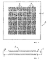
- FIG. 1 depicts a schematic view of a polymer film, hereinafter referred to as PEM 2.
- the PEM layer 2 comprises various treated sections, hereinafter referred to as active sections 4, which are separated from each other by separation bands 6.
- the active sections 4 have been generated by irradiation of these sections with an electron beam having a predetermined irradiation profile in order to both define irradiated sections and to form reactive centers, i.e.
- radicals in said irradiated sections of the PEM layer 2 and by subsequently exposing the irradiated sections of the PEM layer 2 to a monomer or a mixture of monomers amenable to radical polymerization in order to achieve the formation of a graft copolymer in said irradiated sections, followed by further chemical steps, such as sulfonation, in order to arrive at the final product of an active section 4 with respect to fuel cell functionality.
- the active sections 4 are separated from each other by the separation bands 6.
- the separation bands 6 can be subjected to a separate irradiation and chemical modification step in order to introduce specific properties even in these initially un-irradiated and un-grafted separation bands 6 in the PEM layer 2.
- suitable materials for the PEM layer 2, suitable irradiation steps and profiles and suitable grafting conditions and materials are proposed in the international patent application PCT/EP2004/010252 .
- the use of the predetermined irradiation profile applied to the PEM layer 2 allows therefore to generate this active sections 4 which have full fuel cell ion exchange functionality.
- the sections 4 are all placed within the same plane of the PEM layer 2.
- the separation bands 6 in between the active sections 4 serve the purpose of stabilizing the regions comprising the active sections 4 since these separation bands 6 are sections having no ion exchange functionality and therefore they are not subject to bulging and buckling.
- the periphery 8 of the PEM layer 2 has the same properties as the separation bands 6 and serves sealing purposes, thereby offering an inert contact to a bipolar plate since the PEM layer 2 in its untreated status is an insulator and fluid tight separator.
- Figure 2 is a schematic cross sectional view through an active section 4 of the PEM layer 2.
- the active section 4 has been treated prior to the irradiation and chemical modification steps by an imprinting step to reduce its thickness to a smaller thickness d 2 as compared to the normal thickness d 1 of the separation bands 6.
- this figure shows the mechanical structuring of the film prior to modification through irradiation and grafting by introducing a ridged structure within an active section 4.
- the ridged structure is advantageous in the sense of offering spare volume to balance any swelling which otherwise would lead to bulging/buckling of the active sections 4 upon chemical modification.
- FIG. 3 now schematically illustrates a fuel cell module 10 having a number of fuel cell sections 12a, 12b, 12c and 12d which are connected electrically in series by electric conductors 14.
- Each cell section 12a to 12d comprises an active section 4 of the PEM layer 2, a cathode 16 and an anode 18.
- an oxygen containing gas can be supplied in a cathode chamber 20, which is commonly used for all cathodes 16.
- a hydrogen or methanol containing fluid can be supplied in an anode chamber 22 which is commonly used for all anodes 18.
- cathode chambers 20 and anode chambers 22 simplify the design of the full cell module 10 tremendously since between the single fuel cell sections 12a to 12d additional insulation material is obsolete.
- the electric conductors 14 have to penetrate through the PEM layer 2 in the sections of the separation bands 6. Since the untreated separation bands 6 do not have ion exchange properties and can therefore be considered insulating, the electric conductors 14 do not have to be insulated specifically.
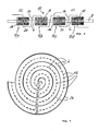
- FIG 4 finally illustrates one design option for a fuel cell module which can be derived from the new fuel cell arrangement which might be called a "Multi-cell-in-one-layer-concept".
- the full cell module shown in Figure 4 comprises a wound PEM layer comprising a plurality of fuel cells 12.
- the active regions and thereby the fuel cells 12 are separated from each other by separation bands 6 which are in Figure 4 shown as the gaps in the dashed line which stands for the PEM layer.
- the separation bands can be used in this embodiment as joints for the wound structure when the fuel cells 12 are substantially planar.
- the windings are separated from each other by an intermediate layer 24 which essentially serves the purpose of separating the cathode chamber 20 from the anode chamber 22 in the next winding. It can be easily seen from this example that the "Multi-cell-in-one-layer-concept" offers a variety of new fuel cell design concepts which have not been accessible with the prior art stack technology of substantially parallel and planar fuel cells.
Landscapes
- Chemical & Material Sciences (AREA)
- Manufacturing & Machinery (AREA)
- Engineering & Computer Science (AREA)
- Chemical Kinetics & Catalysis (AREA)
- General Chemical & Material Sciences (AREA)
- Sustainable Energy (AREA)
- Electrochemistry (AREA)
- Life Sciences & Earth Sciences (AREA)
- Sustainable Development (AREA)
- Health & Medical Sciences (AREA)
- Polymers & Plastics (AREA)
- Transplantation (AREA)
- Materials Engineering (AREA)
- Medicinal Chemistry (AREA)
- Inorganic Chemistry (AREA)
- Organic Chemistry (AREA)
- Physics & Mathematics (AREA)
- Spectroscopy & Molecular Physics (AREA)
- Fuel Cell (AREA)
- Graft Or Block Polymers (AREA)
- Treatments Of Macromolecular Shaped Articles (AREA)
- Printers Or Recording Devices Using Electromagnetic And Radiation Means (AREA)
- Separation Using Semi-Permeable Membranes (AREA)
Claims (7)
- Membranelektrodenanordnung (10), einen Polymerelektrolyten (2) umfassend, welcher zwischen einer Kathodenschicht (16) und einer Anodenschicht (18) sandwichartig angeordnet ist, dadurch gekennzeichnet, dass
die besagte Polymerelektrolytschicht (2) eine Polymerfolie ist, die eine Vielzahl von Abschnitten (4) aufweist, wobei diese Abschnitte (4) unter Verwendung eines vorbestimmten Bestrahlungsprofils strahlungsgepfropft und sulfoniert sind, wobei das besagte vorbestimmte Bestrahlungsprofil einen Bestrahlungsgradienten liefert, der sich von den Rändern (6, 8) der zu bestrahlenden Abschnitte (4) zu den inneren Bereichen der zu bestrahlenden Abschnitte (4) hin erhöht, wobei die besagten Abschnitte (4) durch Trennbänder (6) voneinander getrennt sind, wobei die Trennbänder (6) unbehandelte Abschnitte der ursprünglichen Polymerelektrolytschicht (2) sind; wodurch die besagten Trennbänder (6) ein Isolator und fluiddichter Separator der Abschnitte (4) sind. - Verfahren zur Herstellung einer Membran (2) für die Anordnung in einer Membranelektrodenanordnung (10), die folgenden Schritte umfassend:a) Bestrahlen von Abschnitten (4) der Polymerfolie (2) mit elektromagnetischer und/oder Teilchenstrahlung mit einem vorbestimmten Bestrahlungsprofil, um sowohl bestrahlte Abschnitte (4) zu definieren als auch reaktive Zentren, d.h. Radikale, in den besagten bestrahlten Abschnitten (4) der Folie zu bilden, wobei das besagte vorbestimmte Bestrahlungsprofil so gewählt wird, dass es einen Bestrahlungsgradienten liefert, der sich von den Rändern (6, 8) der zu bestrahlenden Abschnitte (4) zu den inneren Bereichen der zu bestrahlenden Abschnitte (4) hin erhöht, wobei die bestrahlten Abschnitte (4) durch Trennbänder (6) aus unbestrahlten Folienabschnitten voneinander getrennt werden; wobei die besagten Trennbänder (6) isolierend und fluiddicht sind;b) Aussetzen der Folie (2), welche die bestrahlten Abschnitte (4) umfasst, gegenüber einem Monomer oder einem Gemisch von einer Radikalpolymerisation zugänglichen Monomeren, um die Bildung eines Pfropfcopolymers in den besagten bestrahlten Abschnitten (4) zu erzielen.
- Verfahren nach Anspruch 2, wobei das besagte vorbestimmte Bestrahlungsprofil gitterförmig ist.
- Verfahren nach Anspruch 2 oder 3, wobei die Dicke (d2) der Membran in den zu bestrahlenden Abschnitten (4) im Vergleich zu der Dicke (d1) der Membran (2) in den Trennbändern (6), welche unbestrahlt bleiben, reduziert ist.
- Verfahren nach einem der vorhergehenden Ansprüche 2 bis 4, wobei die zu bestrahlenden Abschnitte einem Schritt des Eindruckens (Imprinting) ausgesetzt werden, um eine dreidimensionale Membranstruktur zu erzeugen.
- Verfahren nach einem der vorhergehenden Ansprüche 2 bis 5, wobei die Schritte des Bestrahlens und der anschließenden chemischen Veränderung unter Verwendung unterschiedlicher Bestrahlungsprofile bzw. unterschiedlicher chemischer Verbindungen oder Vorläufer derselben wiederholt durchgeführt werden.
- Verfahren nach einem der vorhergehenden Ansprüche 2 bis 6, wobei
weitere Schritte, wie etwa eine Sulfonierung der gepfropften Komponente, angewendet werden, um die gewünschte Funktionalität der Protonenleitung in den besagten bestrahlten Abschnitten (4) zu bewirken.
Priority Applications (1)
| Application Number | Priority Date | Filing Date | Title |
|---|---|---|---|
| EP06703834A EP1844516B1 (de) | 2005-02-04 | 2006-01-25 | Verfahren zur herstellung einer membran für die anordnung in einer membranelektrodenanordnung und membranelektrodenanordnung |
Applications Claiming Priority (3)
| Application Number | Priority Date | Filing Date | Title |
|---|---|---|---|
| EP05002446A EP1689014A1 (de) | 2005-02-04 | 2005-02-04 | Verfahren zur Herstellung einer Membran für eine Membran-Elektroden-Anordnung und Membran-Elektroden-Anordnung |
| EP06703834A EP1844516B1 (de) | 2005-02-04 | 2006-01-25 | Verfahren zur herstellung einer membran für die anordnung in einer membranelektrodenanordnung und membranelektrodenanordnung |
| PCT/EP2006/000628 WO2006081970A2 (en) | 2005-02-04 | 2006-01-25 | A method for preparing a membrane to be assembled in a membrane electrode assembly and membrane electrode assembly |
Publications (2)
| Publication Number | Publication Date |
|---|---|
| EP1844516A2 EP1844516A2 (de) | 2007-10-17 |
| EP1844516B1 true EP1844516B1 (de) | 2011-03-23 |
Family
ID=34933608
Family Applications (2)
| Application Number | Title | Priority Date | Filing Date |
|---|---|---|---|
| EP05002446A Withdrawn EP1689014A1 (de) | 2005-02-04 | 2005-02-04 | Verfahren zur Herstellung einer Membran für eine Membran-Elektroden-Anordnung und Membran-Elektroden-Anordnung |
| EP06703834A Expired - Lifetime EP1844516B1 (de) | 2005-02-04 | 2006-01-25 | Verfahren zur herstellung einer membran für die anordnung in einer membranelektrodenanordnung und membranelektrodenanordnung |
Family Applications Before (1)
| Application Number | Title | Priority Date | Filing Date |
|---|---|---|---|
| EP05002446A Withdrawn EP1689014A1 (de) | 2005-02-04 | 2005-02-04 | Verfahren zur Herstellung einer Membran für eine Membran-Elektroden-Anordnung und Membran-Elektroden-Anordnung |
Country Status (6)
| Country | Link |
|---|---|
| US (1) | US20090053611A1 (de) |
| EP (2) | EP1689014A1 (de) |
| CN (1) | CN100521346C (de) |
| AT (1) | ATE503282T1 (de) |
| DE (1) | DE602006020840D1 (de) |
| WO (1) | WO2006081970A2 (de) |
Families Citing this family (4)
| Publication number | Priority date | Publication date | Assignee | Title |
|---|---|---|---|---|
| DE102011003746B4 (de) * | 2011-02-08 | 2017-12-28 | Fraunhofer-Gesellschaft zur Förderung der angewandten Forschung e.V. | Ionenleitender Festkörperseparator sowie dessen Herstellung und Verwendung |
| US9385389B2 (en) * | 2011-05-20 | 2016-07-05 | Sanyo Electric Co., Ltd. | Fuel cell |
| DE102017204717A1 (de) * | 2017-03-21 | 2018-09-27 | Robert Bosch Gmbh | PEM-Membran-Elektroden-Einheit, PEM-Zelle und Verfahren zum Herstellen einer PEM-Membran-Elektroden-Einheit |
| EP4148841A4 (de) * | 2020-12-31 | 2025-06-11 | Kolon Industries, Inc. | Membranelektrodenanordnung und herstellungsverfahren dafür |
Family Cites Families (6)
| Publication number | Priority date | Publication date | Assignee | Title |
|---|---|---|---|---|
| US5591539A (en) * | 1993-04-13 | 1997-01-07 | Pall Corporation | Electrolytically conductive battery separator polymeric film |
| NL1014402C1 (nl) * | 2000-02-17 | 2001-08-20 | Nedstack Holding B V | Methode voor het vervaardigen van versterkte membranen voor polymeer Elektrolyt Brandstofcellen. |
| JP2002198068A (ja) * | 2000-12-26 | 2002-07-12 | Aisin Seiki Co Ltd | 固体高分子電解質膜及びその製造方法 |
| WO2003018655A1 (en) * | 2001-08-27 | 2003-03-06 | Ballard Power Systems Inc. | Process for preparing graft copolymer membranes |
| WO2004051782A1 (en) * | 2002-06-28 | 2004-06-17 | Dubitsky Yuri A | Fuel cell incorporating a polymer electrolyte membrane grafted by irradiation |
| WO2005014702A1 (en) * | 2003-07-24 | 2005-02-17 | Paul Scherrer Institut | Method for grafting a chemical compound to a support substrate |
-
2005
- 2005-02-04 EP EP05002446A patent/EP1689014A1/de not_active Withdrawn
-
2006
- 2006-01-25 CN CNB2006800040638A patent/CN100521346C/zh not_active Expired - Fee Related
- 2006-01-25 DE DE602006020840T patent/DE602006020840D1/de not_active Expired - Lifetime
- 2006-01-25 WO PCT/EP2006/000628 patent/WO2006081970A2/en not_active Ceased
- 2006-01-25 EP EP06703834A patent/EP1844516B1/de not_active Expired - Lifetime
- 2006-01-25 US US11/883,143 patent/US20090053611A1/en not_active Abandoned
- 2006-01-25 AT AT06703834T patent/ATE503282T1/de not_active IP Right Cessation
Also Published As
| Publication number | Publication date |
|---|---|
| ATE503282T1 (de) | 2011-04-15 |
| EP1844516A2 (de) | 2007-10-17 |
| CN101116214A (zh) | 2008-01-30 |
| WO2006081970A3 (en) | 2007-05-31 |
| WO2006081970A2 (en) | 2006-08-10 |
| EP1689014A1 (de) | 2006-08-09 |
| CN100521346C (zh) | 2009-07-29 |
| DE602006020840D1 (de) | 2011-05-05 |
| US20090053611A1 (en) | 2009-02-26 |
Similar Documents
| Publication | Publication Date | Title |
|---|---|---|
| US5958616A (en) | Membrane and electrode structure for methanol fuel cell | |
| EP0979534B1 (de) | Polymerelektrolyt-membran-brennstoffzelle mit fluidverteilungsschicht mit integrierter dichtung | |
| EP2612390B1 (de) | Anordnung für eine umkehrbare brennstoffzelle | |
| Kumar et al. | Enhanced performance of direct methanol fuel cells: a study on the combined effect of various supporting electrolytes, flow channel designs and operating temperatures | |
| WO2000002273A2 (en) | Electrochemical fuel cell having a membrane electrode assembly formed in-situ and methods for forming same | |
| CA2696233C (en) | Single fuel cell with thickness control layer | |
| WO2005014468A2 (en) | Method and system for producing high-pressure hydrogen | |
| US8148436B2 (en) | Ion/electron-conducting composite polymer membrane, manufacturing processes thereof and planar fuel cell core comprising it | |
| KR20170012311A (ko) | 전기 화학 셀에 사용하기 위한 유동장들 | |
| EP1518289B1 (de) | Brennstoffzelle mit durch strahlung gepfropfter polymer-elektrolyt-membran | |
| US20080145732A1 (en) | Proton Exchange Fuel Cell | |
| EP1844516B1 (de) | Verfahren zur herstellung einer membran für die anordnung in einer membranelektrodenanordnung und membranelektrodenanordnung | |
| US8617760B2 (en) | Localized deactivation of a membrane | |
| US6979510B2 (en) | Solid polymer electrolyte membrane of a fuel cell and method for producing the same | |
| US20180233760A1 (en) | Polymer electrolyte fuel cells and production method thereof | |
| JP4296667B2 (ja) | 触媒電極および該触媒電極の製造方法並びに燃料電池 | |
| WO2009067617A1 (en) | Fuel cell flow field plate assembly | |
| KR102375457B1 (ko) | 전해조용 채칼형 유로구조 및 그 유로구조를 갖는 고분자 전해질 전해조 | |
| US20090181281A1 (en) | Electrochemical cell bipolar plate | |
| KR101355543B1 (ko) | 메탈폼의 제조방법 및 이 메탈폼이 구비된 전기화학 스택 | |
| Zawodzinski et al. | The Evolution of Fuel Cells and Their Components | |
| JP2004220995A (ja) | 膜−電極接合体、その製造方法、及び燃料電池 | |
| JP5405783B2 (ja) | 燃料電池用触媒層、燃料電池用触媒層転写シート、燃料電池用ガス拡散電極、燃料電池用膜電極接合体、および燃料電池 | |
| JP2012099332A (ja) | 燃料電池システム | |
| WO2006039464A1 (en) | Gas barrier for electrochemical cells |
Legal Events
| Date | Code | Title | Description |
|---|---|---|---|
| PUAI | Public reference made under article 153(3) epc to a published international application that has entered the european phase |
Free format text: ORIGINAL CODE: 0009012 |
|
| 17P | Request for examination filed |
Effective date: 20070725 |
|
| AK | Designated contracting states |
Kind code of ref document: A2 Designated state(s): AT BE BG CH CY CZ DE DK EE ES FI FR GB GR HU IE IS IT LI LT LU LV MC NL PL PT RO SE SI SK TR |
|
| AX | Request for extension of the european patent |
Extension state: AL BA HR MK YU |
|
| RIN1 | Information on inventor provided before grant (corrected) |
Inventor name: GUBLER, LORENZ Inventor name: GUERSEL, SELMIYE, ALKAN Inventor name: SCHERER, GUENTHER, G. |
|
| DAX | Request for extension of the european patent (deleted) | ||
| 17Q | First examination report despatched |
Effective date: 20091126 |
|
| RIC1 | Information provided on ipc code assigned before grant |
Ipc: C08J 7/18 20060101ALI20100806BHEP Ipc: H01M 8/10 20060101AFI20100806BHEP |
|
| GRAP | Despatch of communication of intention to grant a patent |
Free format text: ORIGINAL CODE: EPIDOSNIGR1 |
|
| GRAS | Grant fee paid |
Free format text: ORIGINAL CODE: EPIDOSNIGR3 |
|
| GRAA | (expected) grant |
Free format text: ORIGINAL CODE: 0009210 |
|
| AK | Designated contracting states |
Kind code of ref document: B1 Designated state(s): AT BE BG CH CY CZ DE DK EE ES FI FR GB GR HU IE IS IT LI LT LU LV MC NL PL PT RO SE SI SK TR |
|
| REG | Reference to a national code |
Ref country code: GB Ref legal event code: FG4D |
|
| REG | Reference to a national code |
Ref country code: CH Ref legal event code: EP Ref country code: CH Ref legal event code: NV Representative=s name: SIEMENS SCHWEIZ AG |
|
| REG | Reference to a national code |
Ref country code: IE Ref legal event code: FG4D |
|
| REF | Corresponds to: |
Ref document number: 602006020840 Country of ref document: DE Date of ref document: 20110505 Kind code of ref document: P |
|
| REG | Reference to a national code |
Ref country code: DE Ref legal event code: R096 Ref document number: 602006020840 Country of ref document: DE Effective date: 20110505 |
|
| REG | Reference to a national code |
Ref country code: NL Ref legal event code: VDEP Effective date: 20110323 |
|
| PG25 | Lapsed in a contracting state [announced via postgrant information from national office to epo] |
Ref country code: SE Free format text: LAPSE BECAUSE OF FAILURE TO SUBMIT A TRANSLATION OF THE DESCRIPTION OR TO PAY THE FEE WITHIN THE PRESCRIBED TIME-LIMIT Effective date: 20110323 Ref country code: GR Free format text: LAPSE BECAUSE OF FAILURE TO SUBMIT A TRANSLATION OF THE DESCRIPTION OR TO PAY THE FEE WITHIN THE PRESCRIBED TIME-LIMIT Effective date: 20110624 Ref country code: LT Free format text: LAPSE BECAUSE OF FAILURE TO SUBMIT A TRANSLATION OF THE DESCRIPTION OR TO PAY THE FEE WITHIN THE PRESCRIBED TIME-LIMIT Effective date: 20110323 Ref country code: LV Free format text: LAPSE BECAUSE OF FAILURE TO SUBMIT A TRANSLATION OF THE DESCRIPTION OR TO PAY THE FEE WITHIN THE PRESCRIBED TIME-LIMIT Effective date: 20110323 |
|
| LTIE | Lt: invalidation of european patent or patent extension |
Effective date: 20110323 |
|
| PG25 | Lapsed in a contracting state [announced via postgrant information from national office to epo] |
Ref country code: FI Free format text: LAPSE BECAUSE OF FAILURE TO SUBMIT A TRANSLATION OF THE DESCRIPTION OR TO PAY THE FEE WITHIN THE PRESCRIBED TIME-LIMIT Effective date: 20110323 Ref country code: AT Free format text: LAPSE BECAUSE OF FAILURE TO SUBMIT A TRANSLATION OF THE DESCRIPTION OR TO PAY THE FEE WITHIN THE PRESCRIBED TIME-LIMIT Effective date: 20110323 Ref country code: CY Free format text: LAPSE BECAUSE OF FAILURE TO SUBMIT A TRANSLATION OF THE DESCRIPTION OR TO PAY THE FEE WITHIN THE PRESCRIBED TIME-LIMIT Effective date: 20110323 Ref country code: BG Free format text: LAPSE BECAUSE OF FAILURE TO SUBMIT A TRANSLATION OF THE DESCRIPTION OR TO PAY THE FEE WITHIN THE PRESCRIBED TIME-LIMIT Effective date: 20110623 Ref country code: SI Free format text: LAPSE BECAUSE OF FAILURE TO SUBMIT A TRANSLATION OF THE DESCRIPTION OR TO PAY THE FEE WITHIN THE PRESCRIBED TIME-LIMIT Effective date: 20110323 |
|
| PG25 | Lapsed in a contracting state [announced via postgrant information from national office to epo] |
Ref country code: BE Free format text: LAPSE BECAUSE OF FAILURE TO SUBMIT A TRANSLATION OF THE DESCRIPTION OR TO PAY THE FEE WITHIN THE PRESCRIBED TIME-LIMIT Effective date: 20110323 |
|
| PG25 | Lapsed in a contracting state [announced via postgrant information from national office to epo] |
Ref country code: EE Free format text: LAPSE BECAUSE OF FAILURE TO SUBMIT A TRANSLATION OF THE DESCRIPTION OR TO PAY THE FEE WITHIN THE PRESCRIBED TIME-LIMIT Effective date: 20110323 Ref country code: PT Free format text: LAPSE BECAUSE OF FAILURE TO SUBMIT A TRANSLATION OF THE DESCRIPTION OR TO PAY THE FEE WITHIN THE PRESCRIBED TIME-LIMIT Effective date: 20110725 |
|
| PG25 | Lapsed in a contracting state [announced via postgrant information from national office to epo] |
Ref country code: IS Free format text: LAPSE BECAUSE OF FAILURE TO SUBMIT A TRANSLATION OF THE DESCRIPTION OR TO PAY THE FEE WITHIN THE PRESCRIBED TIME-LIMIT Effective date: 20110723 Ref country code: SK Free format text: LAPSE BECAUSE OF FAILURE TO SUBMIT A TRANSLATION OF THE DESCRIPTION OR TO PAY THE FEE WITHIN THE PRESCRIBED TIME-LIMIT Effective date: 20110323 Ref country code: ES Free format text: LAPSE BECAUSE OF FAILURE TO SUBMIT A TRANSLATION OF THE DESCRIPTION OR TO PAY THE FEE WITHIN THE PRESCRIBED TIME-LIMIT Effective date: 20110704 Ref country code: CZ Free format text: LAPSE BECAUSE OF FAILURE TO SUBMIT A TRANSLATION OF THE DESCRIPTION OR TO PAY THE FEE WITHIN THE PRESCRIBED TIME-LIMIT Effective date: 20110323 Ref country code: RO Free format text: LAPSE BECAUSE OF FAILURE TO SUBMIT A TRANSLATION OF THE DESCRIPTION OR TO PAY THE FEE WITHIN THE PRESCRIBED TIME-LIMIT Effective date: 20110323 |
|
| PG25 | Lapsed in a contracting state [announced via postgrant information from national office to epo] |
Ref country code: NL Free format text: LAPSE BECAUSE OF FAILURE TO SUBMIT A TRANSLATION OF THE DESCRIPTION OR TO PAY THE FEE WITHIN THE PRESCRIBED TIME-LIMIT Effective date: 20110323 |
|
| PLBE | No opposition filed within time limit |
Free format text: ORIGINAL CODE: 0009261 |
|
| STAA | Information on the status of an ep patent application or granted ep patent |
Free format text: STATUS: NO OPPOSITION FILED WITHIN TIME LIMIT |
|
| 26N | No opposition filed |
Effective date: 20111227 |
|
| PG25 | Lapsed in a contracting state [announced via postgrant information from national office to epo] |
Ref country code: PL Free format text: LAPSE BECAUSE OF FAILURE TO SUBMIT A TRANSLATION OF THE DESCRIPTION OR TO PAY THE FEE WITHIN THE PRESCRIBED TIME-LIMIT Effective date: 20110323 Ref country code: DK Free format text: LAPSE BECAUSE OF FAILURE TO SUBMIT A TRANSLATION OF THE DESCRIPTION OR TO PAY THE FEE WITHIN THE PRESCRIBED TIME-LIMIT Effective date: 20110323 |
|
| REG | Reference to a national code |
Ref country code: DE Ref legal event code: R097 Ref document number: 602006020840 Country of ref document: DE Effective date: 20111227 |
|
| PG25 | Lapsed in a contracting state [announced via postgrant information from national office to epo] |
Ref country code: IT Free format text: LAPSE BECAUSE OF FAILURE TO SUBMIT A TRANSLATION OF THE DESCRIPTION OR TO PAY THE FEE WITHIN THE PRESCRIBED TIME-LIMIT Effective date: 20110323 |
|
| PG25 | Lapsed in a contracting state [announced via postgrant information from national office to epo] |
Ref country code: MC Free format text: LAPSE BECAUSE OF NON-PAYMENT OF DUE FEES Effective date: 20120131 |
|
| REG | Reference to a national code |
Ref country code: CH Ref legal event code: PL |
|
| GBPC | Gb: european patent ceased through non-payment of renewal fee |
Effective date: 20120125 |
|
| REG | Reference to a national code |
Ref country code: FR Ref legal event code: ST Effective date: 20120928 |
|
| REG | Reference to a national code |
Ref country code: IE Ref legal event code: MM4A |
|
| PG25 | Lapsed in a contracting state [announced via postgrant information from national office to epo] |
Ref country code: LI Free format text: LAPSE BECAUSE OF NON-PAYMENT OF DUE FEES Effective date: 20120131 Ref country code: GB Free format text: LAPSE BECAUSE OF NON-PAYMENT OF DUE FEES Effective date: 20120125 Ref country code: DE Free format text: LAPSE BECAUSE OF NON-PAYMENT OF DUE FEES Effective date: 20120801 Ref country code: CH Free format text: LAPSE BECAUSE OF NON-PAYMENT OF DUE FEES Effective date: 20120131 |
|
| REG | Reference to a national code |
Ref country code: DE Ref legal event code: R119 Ref document number: 602006020840 Country of ref document: DE Effective date: 20120801 |
|
| PG25 | Lapsed in a contracting state [announced via postgrant information from national office to epo] |
Ref country code: FR Free format text: LAPSE BECAUSE OF NON-PAYMENT OF DUE FEES Effective date: 20120131 |
|
| PG25 | Lapsed in a contracting state [announced via postgrant information from national office to epo] |
Ref country code: IE Free format text: LAPSE BECAUSE OF NON-PAYMENT OF DUE FEES Effective date: 20120125 |
|
| PG25 | Lapsed in a contracting state [announced via postgrant information from national office to epo] |
Ref country code: TR Free format text: LAPSE BECAUSE OF FAILURE TO SUBMIT A TRANSLATION OF THE DESCRIPTION OR TO PAY THE FEE WITHIN THE PRESCRIBED TIME-LIMIT Effective date: 20110323 |
|
| PG25 | Lapsed in a contracting state [announced via postgrant information from national office to epo] |
Ref country code: LU Free format text: LAPSE BECAUSE OF NON-PAYMENT OF DUE FEES Effective date: 20120125 |
|
| PG25 | Lapsed in a contracting state [announced via postgrant information from national office to epo] |
Ref country code: HU Free format text: LAPSE BECAUSE OF FAILURE TO SUBMIT A TRANSLATION OF THE DESCRIPTION OR TO PAY THE FEE WITHIN THE PRESCRIBED TIME-LIMIT Effective date: 20060125 |