EP1844512B1 - Method of producing metal to glass, metal to metal or metal to ceramic connections - Google Patents
Method of producing metal to glass, metal to metal or metal to ceramic connections Download PDFInfo
- Publication number
- EP1844512B1 EP1844512B1 EP05822618.4A EP05822618A EP1844512B1 EP 1844512 B1 EP1844512 B1 EP 1844512B1 EP 05822618 A EP05822618 A EP 05822618A EP 1844512 B1 EP1844512 B1 EP 1844512B1
- Authority
- EP
- European Patent Office
- Prior art keywords
- metal
- oxide
- glass
- powder
- coated
- Prior art date
- Legal status (The legal status is an assumption and is not a legal conclusion. Google has not performed a legal analysis and makes no representation as to the accuracy of the status listed.)
- Expired - Lifetime
Links
Images

Classifications
-
- H—ELECTRICITY
- H01—ELECTRIC ELEMENTS
- H01M—PROCESSES OR MEANS, e.g. BATTERIES, FOR THE DIRECT CONVERSION OF CHEMICAL ENERGY INTO ELECTRICAL ENERGY
- H01M8/00—Fuel cells; Manufacture thereof
- H01M8/02—Details
-
- C—CHEMISTRY; METALLURGY
- C03—GLASS; MINERAL OR SLAG WOOL
- C03C—CHEMICAL COMPOSITION OF GLASSES, GLAZES OR VITREOUS ENAMELS; SURFACE TREATMENT OF GLASS; SURFACE TREATMENT OF FIBRES OR FILAMENTS MADE FROM GLASS, MINERALS OR SLAGS; JOINING GLASS TO GLASS OR OTHER MATERIALS
- C03C27/00—Joining pieces of glass to pieces of other inorganic material; Joining glass to glass other than by fusing
- C03C27/04—Joining glass to metal by means of an interlayer
- C03C27/042—Joining glass to metal by means of an interlayer consisting of a combination of materials selected from glass, glass-ceramic or ceramic material with metals, metal oxides or metal salts
-
- C—CHEMISTRY; METALLURGY
- C03—GLASS; MINERAL OR SLAG WOOL
- C03C—CHEMICAL COMPOSITION OF GLASSES, GLAZES OR VITREOUS ENAMELS; SURFACE TREATMENT OF GLASS; SURFACE TREATMENT OF FIBRES OR FILAMENTS MADE FROM GLASS, MINERALS OR SLAGS; JOINING GLASS TO GLASS OR OTHER MATERIALS
- C03C27/00—Joining pieces of glass to pieces of other inorganic material; Joining glass to glass other than by fusing
- C03C27/04—Joining glass to metal by means of an interlayer
-
- C—CHEMISTRY; METALLURGY
- C03—GLASS; MINERAL OR SLAG WOOL
- C03C—CHEMICAL COMPOSITION OF GLASSES, GLAZES OR VITREOUS ENAMELS; SURFACE TREATMENT OF GLASS; SURFACE TREATMENT OF FIBRES OR FILAMENTS MADE FROM GLASS, MINERALS OR SLAGS; JOINING GLASS TO GLASS OR OTHER MATERIALS
- C03C29/00—Joining metals with the aid of glass
-
- C—CHEMISTRY; METALLURGY
- C03—GLASS; MINERAL OR SLAG WOOL
- C03C—CHEMICAL COMPOSITION OF GLASSES, GLAZES OR VITREOUS ENAMELS; SURFACE TREATMENT OF GLASS; SURFACE TREATMENT OF FIBRES OR FILAMENTS MADE FROM GLASS, MINERALS OR SLAGS; JOINING GLASS TO GLASS OR OTHER MATERIALS
- C03C8/00—Enamels; Glazes; Fusion seal compositions being frit compositions having non-frit additions
- C03C8/24—Fusion seal compositions being frit compositions having non-frit additions, i.e. for use as seals between dissimilar materials, e.g. glass and metal; Glass solders
-
- C—CHEMISTRY; METALLURGY
- C04—CEMENTS; CONCRETE; ARTIFICIAL STONE; CERAMICS; REFRACTORIES
- C04B—LIME, MAGNESIA; SLAG; CEMENTS; COMPOSITIONS THEREOF, e.g. MORTARS, CONCRETE OR LIKE BUILDING MATERIALS; ARTIFICIAL STONE; CERAMICS; REFRACTORIES; TREATMENT OF NATURAL STONE
- C04B37/00—Joining burned ceramic articles with other burned ceramic articles or other articles by heating
- C04B37/02—Joining burned ceramic articles with other burned ceramic articles or other articles by heating with metallic articles
-
- C—CHEMISTRY; METALLURGY
- C04—CEMENTS; CONCRETE; ARTIFICIAL STONE; CERAMICS; REFRACTORIES
- C04B—LIME, MAGNESIA; SLAG; CEMENTS; COMPOSITIONS THEREOF, e.g. MORTARS, CONCRETE OR LIKE BUILDING MATERIALS; ARTIFICIAL STONE; CERAMICS; REFRACTORIES; TREATMENT OF NATURAL STONE
- C04B37/00—Joining burned ceramic articles with other burned ceramic articles or other articles by heating
- C04B37/02—Joining burned ceramic articles with other burned ceramic articles or other articles by heating with metallic articles
- C04B37/023—Joining burned ceramic articles with other burned ceramic articles or other articles by heating with metallic articles characterised by the interlayer used
- C04B37/025—Joining burned ceramic articles with other burned ceramic articles or other articles by heating with metallic articles characterised by the interlayer used consisting of glass or ceramic material
-
- H—ELECTRICITY
- H01—ELECTRIC ELEMENTS
- H01M—PROCESSES OR MEANS, e.g. BATTERIES, FOR THE DIRECT CONVERSION OF CHEMICAL ENERGY INTO ELECTRICAL ENERGY
- H01M8/00—Fuel cells; Manufacture thereof
- H01M8/02—Details
- H01M8/0271—Sealing or supporting means around electrodes, matrices or membranes
- H01M8/028—Sealing means characterised by their material
- H01M8/0282—Inorganic material
-
- B—PERFORMING OPERATIONS; TRANSPORTING
- B32—LAYERED PRODUCTS
- B32B—LAYERED PRODUCTS, i.e. PRODUCTS BUILT-UP OF STRATA OF FLAT OR NON-FLAT, e.g. CELLULAR OR HONEYCOMB, FORM
- B32B2311/00—Metals, their alloys or their compounds
-
- C—CHEMISTRY; METALLURGY
- C04—CEMENTS; CONCRETE; ARTIFICIAL STONE; CERAMICS; REFRACTORIES
- C04B—LIME, MAGNESIA; SLAG; CEMENTS; COMPOSITIONS THEREOF, e.g. MORTARS, CONCRETE OR LIKE BUILDING MATERIALS; ARTIFICIAL STONE; CERAMICS; REFRACTORIES; TREATMENT OF NATURAL STONE
- C04B2237/00—Aspects relating to ceramic laminates or to joining of ceramic articles with other articles by heating
- C04B2237/02—Aspects relating to interlayers, e.g. used to join ceramic articles with other articles by heating
- C04B2237/10—Glass interlayers, e.g. frit or flux
-
- C—CHEMISTRY; METALLURGY
- C04—CEMENTS; CONCRETE; ARTIFICIAL STONE; CERAMICS; REFRACTORIES
- C04B—LIME, MAGNESIA; SLAG; CEMENTS; COMPOSITIONS THEREOF, e.g. MORTARS, CONCRETE OR LIKE BUILDING MATERIALS; ARTIFICIAL STONE; CERAMICS; REFRACTORIES; TREATMENT OF NATURAL STONE
- C04B2237/00—Aspects relating to ceramic laminates or to joining of ceramic articles with other articles by heating
- C04B2237/30—Composition of layers of ceramic laminates or of ceramic or metallic articles to be joined by heating, e.g. Si substrates
- C04B2237/32—Ceramic
- C04B2237/34—Oxidic
- C04B2237/343—Alumina or aluminates
-
- C—CHEMISTRY; METALLURGY
- C04—CEMENTS; CONCRETE; ARTIFICIAL STONE; CERAMICS; REFRACTORIES
- C04B—LIME, MAGNESIA; SLAG; CEMENTS; COMPOSITIONS THEREOF, e.g. MORTARS, CONCRETE OR LIKE BUILDING MATERIALS; ARTIFICIAL STONE; CERAMICS; REFRACTORIES; TREATMENT OF NATURAL STONE
- C04B2237/00—Aspects relating to ceramic laminates or to joining of ceramic articles with other articles by heating
- C04B2237/30—Composition of layers of ceramic laminates or of ceramic or metallic articles to be joined by heating, e.g. Si substrates
- C04B2237/40—Metallic
-
- H—ELECTRICITY
- H01—ELECTRIC ELEMENTS
- H01M—PROCESSES OR MEANS, e.g. BATTERIES, FOR THE DIRECT CONVERSION OF CHEMICAL ENERGY INTO ELECTRICAL ENERGY
- H01M8/00—Fuel cells; Manufacture thereof
- H01M8/10—Fuel cells with solid electrolytes
- H01M8/12—Fuel cells with solid electrolytes operating at high temperature, e.g. with stabilised ZrO2 electrolyte
- H01M2008/1293—Fuel cells with solid oxide electrolytes
-
- Y—GENERAL TAGGING OF NEW TECHNOLOGICAL DEVELOPMENTS; GENERAL TAGGING OF CROSS-SECTIONAL TECHNOLOGIES SPANNING OVER SEVERAL SECTIONS OF THE IPC; TECHNICAL SUBJECTS COVERED BY FORMER USPC CROSS-REFERENCE ART COLLECTIONS [XRACs] AND DIGESTS
- Y02—TECHNOLOGIES OR APPLICATIONS FOR MITIGATION OR ADAPTATION AGAINST CLIMATE CHANGE
- Y02E—REDUCTION OF GREENHOUSE GAS [GHG] EMISSIONS, RELATED TO ENERGY GENERATION, TRANSMISSION OR DISTRIBUTION
- Y02E60/00—Enabling technologies; Technologies with a potential or indirect contribution to GHG emissions mitigation
- Y02E60/30—Hydrogen technology
- Y02E60/50—Fuel cells
-
- Y—GENERAL TAGGING OF NEW TECHNOLOGICAL DEVELOPMENTS; GENERAL TAGGING OF CROSS-SECTIONAL TECHNOLOGIES SPANNING OVER SEVERAL SECTIONS OF THE IPC; TECHNICAL SUBJECTS COVERED BY FORMER USPC CROSS-REFERENCE ART COLLECTIONS [XRACs] AND DIGESTS
- Y02—TECHNOLOGIES OR APPLICATIONS FOR MITIGATION OR ADAPTATION AGAINST CLIMATE CHANGE
- Y02P—CLIMATE CHANGE MITIGATION TECHNOLOGIES IN THE PRODUCTION OR PROCESSING OF GOODS
- Y02P70/00—Climate change mitigation technologies in the production process for final industrial or consumer products
- Y02P70/50—Manufacturing or production processes characterised by the final manufactured product
Definitions
- the present invention relates to a method of producing metal to glass, metal to metal and metal to ceramic connections.
- Said connections may, for example, be used in solid oxide fuel cell (SOFC) applications.
- SOFC solid oxide fuel cell
- SOFCs of the flat plate design comprise a stack of multiple cells, each of them comprising an electrolyte sandwiched by two electrodes.
- the electrodes of each cell are in contact with interconnect layers which make the series connection between the individual cells. Gas tight sealings are virtually important for the performance, durability and safely operation of a fuel cell.
- Glasses are suitable as sealing materials for SOFCs since the physical and chemical properties of glasses can be tailored within a wide range.
- Different glass and glass-ceramic compositions have been examined within the group of alkali silicate, alkali aluminosilicates, alkaline earth silicates, alkaline earth aluminoborosilicates, phosphate and borosilicate glasses.
- alkali silicate, alkali aluminosilicates, alkaline earth silicates, alkaline earth aluminoborosilicates, phosphate and borosilicate glasses have been able to fulfill all the requirements of mechanical performance, e.g. viscosity and match of thermal expansion and chemical compatibility, e.g. wetting and bonding.
- Oxides of the metallic elements themselves are well known constituents in the so-called ground coats when bonding vitreous enamels to ferrous alloys and are characterized by their ability to partially oxidize metallic Fe and form vitreous or mixed oxide phases, often characterized by dendrite formation at various oxidation states, cf. Donald, I. W., "Preparation, properties and chemistry of glass and glass-ceramic-to-metal seals and coatings, J. Mat, Sci. 28 (1993), p. 2841-86 and Eppler, R. A "Glazes and glass coatings", The American Ceramic Society, Westerville, Ohio (2000 ).
- DE 19710345 discloses a material suitable to form contact layers in between an electrode and an interconnect of a solid oxide fuel cell.
- Said material comprises at least two phases, wherein the first phase comprises a glass or glass ceramic, and wherein the second phase has electrical conductivity.
- US 2003/082434 relates to glass sealing compositions which are used at the etches of solid oxide fuel cells and interconnectors to bond a ceramic spacer on top of the interconnector.
- sealing compositions suitable for solid oxide fuel cells comprising alkali silicate glass with additions of magnesium oxide and SYZ. As may be seen from Figure 6 of D3, the sealing composition is directly placed around the electrode and partly in between the electrode and interconnect.
- EP 0446680 discloses a current collector in between two stacked high temperature solid oxide fuel cells.
- Said object is achieved by a method of manufacturing metal to glass, metal to metal, and metal to ceramic connections, characterized by said connections being produced with a mixture comprising a base glass powder and a metal oxide powder having a grain size of 5 ⁇ m or less, wherein the base glass powder is selected from the group consisting of alumosilicates, alkali earth alumoborosilicates and phosphate glasses, and wherein prior to applying the base-glass powder together with the metal oxide on the metal surface, the metal surface is coated with a metallic coating or a transition-metal oxide coating, wherein the bonding is provided at a temperature of from 400°C to 1100°C, at a pressure between 0.1 kPa and 1000 kPa, and for a time of from 0.1 to 10 hours; and wherein the metal oxide powder is selected from the group consisting of boron oxide, magnesium oxide, sodium oxide, potassium oxide, vanadium oxide, manganese oxide, nickel oxide, cobalt oxide, molybdenum oxide and copper oxide.
- the base glass powder is a glass matrix with a high coefficient of thermal expansion.
- the base glass powder is selected from the group consisting of alkali aluminosilicates, (NAS), alkaline earth aluminoborosilicates, (CAS), and phosphate glasses, (MAP), to which metal oxides are added, e.g. magnesium oxide, in order to control the local wetting properties, henceforth referred to as a glassy connection layer.
- NAS alkali aluminosilicates
- CAS alkaline earth aluminoborosilicates
- MAP phosphate glasses
- Alkali alumosilicates, (NAS), suitable for the present invention comprise 10-25 mole % sodium oxide, 40-80 mole % silicon dioxide, 5-20 mole % aluminium oxide, and may optionally comprise 0-10 mole % boric oxide, 0-10 mole % magnesium oxide, 0-10 mole % calcium oxide, 0-10 mole % barium oxide, 0-2 mole % fluorine, and 0-5 mole % phosphor oxide.
- Alkaline earth alumoborosilicates suitable for the present invention comprise 40-80 mole % silicon dioxide, 5-20 mole % aluminium oxide, 20-45 mole % calcium oxide, and may optionally comprise 0-5 mole % sodium oxide, 0-10 mole % boric oxide, 0-10 mole % magnesium oxide, 0-2 mole % barium oxide, 0-2 mole % fluorine, and 0-5 mole % phosphor oxide.
- Phosphate glasses (MAP) suitable for the present invention comprise 5-25 mole % aluminium oxide, 10-30 mole % magnesium oxide, 5-20 mole % calcium oxide, 40-60 mole % phosphor oxide and may optionally comprise 0-5 mole % sodium oxide, 0-12 mole % silicon dioxide, 0-10 mole % boric oxide, 0-5 mole % barium oxide, and 0-2 mole % fluorine.
- Table 1 illustrates the compositional range for the base glasses used as defined above.
- Table 1. Mole % "NAS” "MAP” "CAS” Sodium oxide 10-25 0-5 0-5 Silicon dioxide 40-80 0-12 40-70 Aluminium oxide 5-20 5-25 5-20 Boric oxide 0-10 0-10 0-10 Magnesium oxide 0-10 10-30 0-10 Calcium oxide 0-10 5-20 20-45 Barium oxide 0-10 0-5 0-02 Fluorine 0-2 0-2 0-2 Phosphor oxide 0-5 40-60 0-5
- Interconnects develop a protective chromium-containing scale having a microstructure and composition which depend on the intrinsic alloy.
- surface coatings are applied onto the interconnect which form strong and chemically compatible interfaces between the two components.
- the inherent properties of the glass used in the composite seal parts have been altered locally at the metal-coat interface by addition of e.g. MgO, in order to control the viscosity and wetting, and at the same time maintain the bulk properties, e.g. high coefficient of thermal expansion of the base glass towards the seal components.
- the base glass composition has been selected so that a considerable amount of residual glass remains after bonding and partially crystallization of the glass composite seal and the glassy connection layer.
- the grain size of the base glass powder to be used in accordance with the present invention is preferably from 0.05 ⁇ m to 100 ⁇ m, more preferably from 0.05 ⁇ m to 50 ⁇ m, and most preferred from 0.05 ⁇ m to 30 ⁇ m.
- the grain size of the metal oxide powder to be used with the base glass powder in accordance with the present invention is 5 ⁇ m or less, preferably from 0.05 ⁇ m to 5 ⁇ m, more preferably from 0.05 ⁇ m to 3 ⁇ m, and most preferred from 0.05 ⁇ m to 1.5 ⁇ m.
- the bonding in accordance with the present invention is provided under elevated temperatures, depending on the specific components used, particularly the base glass powder.
- Preferred temperatures for the bonding are from 400°C to 1100°C. It is also preferred to select the temperature to be from 200 to 400°C above the glass transition temperature in question and even more preferred from 250 to 350°C above the glass transition temperature in question.
- the conditions for the bonding are controlled to achieve optimal bonding strength of the connections by firstly supplying air to the joint for oxidizing the organic binder during heat up through a temperature range from room temperature to 550°C. Secondly, at higher temperatures an orthogonal sealing pressure, typically between 0.1 kPa and 1000 kPa and preferably between 10 kPa and 400 kPa is applied and held constant during the bonding process, which typically lasts from 0.1 to 10 hours.
- the metal surface is coated with a metallic coating.
- Said coating may be alloyed into the surface by heating to high temperature, preferably between 750 to 950°C for relatively short time, preferably 0.5 to 5 hours in a controlled atmosphere, where the oxygen and nitrogen partial pressures are held lower than ⁇ 10 -20 bar.
- a transition-metal oxide coating may be applied to the metal surface by spraying or dip-coating prior to the application of the base glass powder and the metal oxide.
- transition metal oxides in particular cobalt-, nickel-, and manganese oxide, which are preferably applied as a surface coating on the metal, together with the glassy connection layer, encompasses a tunable base coat, which is used for instance in a SOFC environment for providing a strong bonding component between the metal parts and the neighbor components in form of glassy composite seal parts, other metal parts or ceramic parts.
- the transition metal oxides may also be added to the glass in smaller amounts.
- Specific connections are produced by coating a composite seal part with a dispersed metal oxide suspension. This may be carried out by, for example, dip coating or spraying.
- Examples of the metal oxides to be added to the base glass powder in order to control the glass wetting properties are boron oxide, magnesium oxide, sodium oxide, potassium oxide and vanadium oxide, with boron oxide, magnesium oxide and sodium oxide being particularly preferred.
- Examples of the metal oxides to be added to the base glass powder or preferably as a surface coat on the metallic part in order to control the glass bonding and adhesion properties are manganese oxide, nickel oxide, cobalt oxide, molybdenum oxide, copper oxide or mixtures thereof.
- Preferred oxides are manganese oxide, nickel oxide, and cobalt oxide, with nickel oxide and cobalt oxide being particularly preferred.
- connections are produced as a mixture of a base glass powder and a metal oxide powder in a binder system.
- Metallic materials have been divided into three groups; one which develops a duplex seal of chromia and Cr-Mn-spinel (exemplified by Krupp-Thyssen, Crofer 22APU), a second which develops a single layer scale of chromia (exemplified by Sandvik 0YC44), and a third which develops a protective alumina scale (exemplified by Fe Cr alloy). Interconnect materials of ferritic chromium steel were cut to shape before treated with surface coatings.
- the surface oxides on the interconnect metal were removed prior to coating by rinsing specimens in a ultrasonic aqueous HF/HN03-bath, followed by a rinse in ethanol and finally dried at 60°C in air.
- Other coatings were applied after degreasing the metal surface in acetone and drying at 60°C in air.
- Silicate glass samples were produced by melting analytical grade chemicals Na 2 CO 3 , SiO 2 Al 2 O 3 , B 2 O 3 , MgO, NaF, and CaCO 2 in a platinum crucible at 1500°C for 4 hr. The glass was quenched, crushed, re-melted and finall milled into powder (d50 ⁇ 5 ⁇ m, as measured by a Beckman coulter I/S particle size analyser).
- Phosphate glasses were prepared by mixing analytical grade MgHPO 4 (3H 2 O), Al(PO 3 ) 3 , H 3 BO 3 and SiO 2 by ball milling, melting in alumina crucibles at 1500°C for 30 minutes while stirring before quenching, crushing and final milling into powder (d50 ⁇ 5 ⁇ m).
- Thin films having a dried thickness of 5-45 ⁇ m were made by screen-printing of glass powder or mixtures of glass powder and metal oxide powders.
- Glass foils typically in the range of 200-400 ⁇ m were made by tape casting of glass powder or mixtures of glass powder and metal oxide powder.
- Table 2 illustrates the three prepared base glass samples. Table 2. Mole % Glass No 1 (“NAS”) Glass No 2 (“MAP”) Glass No 3 (“CAS”) Sodium oxide 17.8 - 0.5 Silicon dioxide 72.8 8.0 39.4 Aluminium oxide 9.4 15.0 10.1 Boric oxide - 2.0 4.5 Magnesium oxide - 30.0 4.6 Calcium oxide - - 40.1 Fluorine - - 0.8 Phosphor oxide - 55.0 -
- a Crofer 22APU (c) was coated with a 15 ⁇ m thick layer of glass No 3/MgO/Co 3 O 4 (4 wt% MgO, 0.5 wt% Co 3 O 4 ) glassy connection layer by screen-printing, (b) in Fig. 2A .
- Glass No 3 was prepared and combined with 72 wt% metal powder (Fe Cr alloy, 90 ⁇ m ⁇ d ⁇ 120 ⁇ m) for the composite seal part (a).
- Metal and composite seal were held together by 400 kPa during heating to 950° for 4 h before cooling to 750°C, where the connection was aged for 500 h before being thermally cycled twice to room temperature.
- a Sandvik 0YC44 (c) was coated with nominally 0.1 ⁇ m metallic nickel (d) and by screen-printing coated with a 45 ⁇ m thick layer of glass No 1/MgO glassy connection layer (2 wt% MgO, d ⁇ 1.1 ⁇ m (b), Cf. Fig. 2 B) .
- Glass No 1 was prepared and combined with 55 wt% coarse MgO for the composite seal part (a).
- Metal and composite seal were held together by 400 kPa during heating to 950° for 4 h before cooling to 750°C in an argon/hydrogen mixture, where the connection was aged for 500 h before being thermally cycled twice to room temperature.
- a Sandvik 0YC44 (c) was coated with nominally 0.1 ⁇ m Mn-metal (d) and preheated in argon (pO 2 ⁇ 10 -20 atm.) to alloy the coating into the surface and after cooling to room temperature coated with a 15 ⁇ m thick layer of glass No 3/MgO/NaO glassy connection layer (10 wt% MgO, d ⁇ 1.3 ⁇ m; 1 wt% Na 2 O, (d ⁇ 2 ⁇ m) by screen printing (b), cf. Fig. 2B .
- Glass No 3 was prepared and combined with 79 wt% metal powder (SS316) for the composite seal part (a). Metal and composite seal were held together by 400 kPa during heating to 950° for 4 h before cooling to 750°C in an argon/hydrogen mixture, where the connection was aged for 500 h before being thermally cycled twice to room temperature.
- a Crofer 22 APU (c) was coated with metallic cobalt (d), cf. Fig. 2B , preheated at 900°C for 2h in argon (pO 2 ⁇ 10 -20 atm.) to alloy the coating into the surface and after cooling to room temperature coated with a thin thick layer of glass No 1/MgO glassy connection layer (20 wt% MgO) by screen printing (b). Glass No 1 was prepared and combined with 55 wt% coarse MgO for the composite seal part (a).
- Metal and composite seal were- heated to 400°C in air and then held together by 400 kPa during heating to 950° for 4 h and cooling to 750° in an argon/hydrogen mixture, where the connection was aged for 500 h before being thermally cycled twice to room temperature.
- a Sandvik 0YC44 (c) was coated with Mn-metal and preheated (d) at 850°C for 0.5 h in argon (pO 2 ⁇ 10 -20 atm.) to alloy the coating into the surface and after cooling to room temperature coated with a 45 ⁇ m thick layer of glass No 1/MgO glassy connection layer (2 wt% MgO) by screen printing, (b) in Fig. 2B .
- Glass No 1 was prepared and combined with 55 wt% coarse MgO for the composite seal part (a).
- Metal and composite seal were heated to 400°C in air and then held together by 400 kPa during heating to 750° for 4 h before cooling to 550°C, where the connection was aged for 500 h before being thermally cycled twice to room temperature.
- a Crofer 22 APU (c) was coated with a 5 ⁇ m thick layer of cobalt oxide (e) and then coated with a 15 ⁇ m thick layer of glass No 1/MgO glassy connection layer (5 wt% MgO) by screen-printing (b), cf. Fig. 2C .
- Glass No 1 was prepared and combined with 55 wt% coarse MgO for the composite seal part (a).
- Metal and composite seal were heated to 400°C in air and then held together by 400 kPa during heating lo 950° for 4 h before cooling to 750°C, where the connection was aged for 500 h before being thermally cycled twice to room temperature.
- a Sandvik 0YC44 (c) was coated with Mn-metal, (d) in Fig. 2D and preheated at 850°C for 0.5 h in argon (pO 2 ⁇ 10 -20 atm.) to ally the coating into the surface.
- the metal was then slurry coated with a 10 ⁇ m thick cobalt oxide (e) preheated in air to 500°C for 0.5 h to alloy and oxidize the coaling and after cooling to room temperature coated with 45 ⁇ m thick layer of glass No 1/MgO/ B 2 O 3 glassy connection layer (2 wt% MgO, d ⁇ 1.1 ⁇ m, 4 wt% B 2 O 3 , d ⁇ 0.8 ⁇ m) by screen printing (b).
- Glass No 1 was prepared and combined with 55 wt% coarse MgO for the composite seal part (a). Metal and composite seal were held together by 400 kPa during heating to 880°C for 4 h before cooling to 750°C, where the connection was aged for 500 h before being thermally cycled twice to room temperature.
- a Sandvik 0YC44 (c) was coated with nominally 0.1 ⁇ m metallic nickel, (d) In Fig. 2B and by screen-printing coated with a 45 ⁇ m thick layer of glass No 3/MgO/Na 2 O (10 wt% MgO, 2 wt% Na 2 O) glassy connection layer (b). Glass No 3 was prepared and combined with 70 vol% metal powder (SS316, 50 ⁇ m ⁇ d ⁇ 140 ⁇ m) for the composite seal part (a). Metal and composite seal were held together by 400 kPa during heating to 950°C for 4 h in air before cooling to 750°C in an argon/hydrogen mixture, where the connection was aged for 500 h before being thermally cycled twice to room temperature.
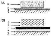
- a Sandvik 0YC44 (c) was spray-coated with nominally 10 ⁇ m layer of nickel oxide (d 25 ⁇ 1.5 ⁇ m) (e) dispersed in a binder system, dried and coated with a 45 ⁇ m thick layer of glass No 3/MgO/NaO glassy connection layer (3 wt% MgO; wt% NaO) by screen printing, (b), cf. Fig- 3 A.
- Magnesium aluminate spinel ceramic was cut to rectangular shape and ground to obtain plane parallel surfaces (h). Metal and ceramic parts were held together by 400 kPa during heating to 950° for 4 h before cooling to 750° in an argon/hydrogen mixture, where the connection was aged for 500 h before being thermally cycled twice to room temperature.
- the powders were mixed with an organic vehicle (paraffin dissolved in EtOH) and composite seal parts made by uniaxial pressing.
- Magnesium manganese spinel (MgMn 2 O 4 ) powder (d 50 2 ⁇ m) was dispersed and mixed with an organic vehicle.
- the composite seal parts were subsequently coated with the spinel-slurry by dip-coating (e).
- a Crofer 22 APU (c) was coated with metallic cobalt (25 ⁇ m/cm 2 ) (d) and preheated at 900°C for 2 h in argon (pO 2 ⁇ 10 -20 atm.) to alloy the coating into the surface. After cooling to room temperature, the metal and the coated seal part were held together by approximately 10 kPa and heated to 900°C, where the load was increased to 40 kPa while keeping the temperature. After 2 h the temperature was reduced to 750°C, where the connection was aged for 500 h before being thermally cycled twice to room temperature.
- a Sandvik 0YC44 (e) was coated with nominally 0.1 ⁇ m metallic nickel, (d) in fig. 3B and by screen-printing coated with a 5 ⁇ m thick layer of cobalt oxide (e).
- Crofer 22APU (g) was coated with a 15 my thick layer of glass No 3/MgO/Co 3 O 4 glassy connection layer by screen-printing (b).
- a Crofer 22APU (c) in Fig. 2A was coated with a 15 ⁇ m thick layer of glass No 2/Co 3 O 4 glassy connection layer (5wt% Co 3 O 4 , d ⁇ 1.5 ⁇ m) by screen-printing (b).
- Glass No 2 was prepared and combined with 79 wt% metal powder (0YC44) for the composite seal part (a).
- Metal and composite seal were held together by 200 kPa during heating to 700°C for 4 h before cooling to 550°C, where the connection was aged for 500 h before being thermally cycled twice to room temperature.
- a Sandvik 0YC44 (c) was coated with Mn-metal, (d) m Fig. 2D and preheated at 850°C for 0.5 h in argon/hydrogen (pO 2 ⁇ 10 -20 atm.) to alloy the coating into the surface.
- the metal was then slurry coated with a 10 ⁇ m thick cobalt oxide layer (e), preheated in air to 800°C for 0.5 h to alloy and oxidize the coating, and after cooling to room temperature coated with 45 ⁇ m thick layer of glass No 2/MgO (2 wt% MgO) glassy connection layer by screen printing (b).
- Glass No 2 was prepared and combined with 55 wt% coarse MgO for the composite seal part (a).
- Metal and composite seal were held together by 100 kPa during heating to 700°C for 4 h before cooling to 550°C, where the connection was aged for 500 h before being thermally cycled twice to room temperature.
Landscapes
- Chemical & Material Sciences (AREA)
- Engineering & Computer Science (AREA)
- Ceramic Engineering (AREA)
- Life Sciences & Earth Sciences (AREA)
- Chemical Kinetics & Catalysis (AREA)
- General Chemical & Material Sciences (AREA)
- Materials Engineering (AREA)
- Organic Chemistry (AREA)
- Geochemistry & Mineralogy (AREA)
- Sustainable Development (AREA)
- Manufacturing & Machinery (AREA)
- Sustainable Energy (AREA)
- Electrochemistry (AREA)
- Structural Engineering (AREA)
- Inorganic Chemistry (AREA)
- Glass Compositions (AREA)
- Fuel Cell (AREA)
- Joining Of Glass To Other Materials (AREA)
- Gasket Seals (AREA)
- Ceramic Products (AREA)
- Other Surface Treatments For Metallic Materials (AREA)
Description
- The present invention relates to a method of producing metal to glass, metal to metal and metal to ceramic connections. Said connections may, for example, be used in solid oxide fuel cell (SOFC) applications.
- Typically, SOFCs of the flat plate design comprise a stack of multiple cells, each of them comprising an electrolyte sandwiched by two electrodes. The electrodes of each cell are in contact with interconnect layers which make the series connection between the individual cells. Gas tight sealings are virtually important for the performance, durability and safely operation of a fuel cell.
- Glasses are suitable as sealing materials for SOFCs since the physical and chemical properties of glasses can be tailored within a wide range. Different glass and glass-ceramic compositions have been examined within the group of alkali silicate, alkali aluminosilicates, alkaline earth silicates, alkaline earth aluminoborosilicates, phosphate and borosilicate glasses. However, even though promising results have been reported, none of them have been able to fulfill all the requirements of mechanical performance, e.g. viscosity and match of thermal expansion and chemical compatibility, e.g. wetting and bonding.
- Composite seals with crystalline filler materials dispersed into base glass, e.g. alkali borosilicate glass, or in sodium aluminosilicate glass, have shown promising results in relation to exact matching the coefficient of thermal expansion (CTE) between the sealant and the seal surfaces. At the same time, suitable viscosities at the sealing temperature have been obtained.
- However, an optimization of the bonding to metal surfaces is still required, and particularly a bonding to the corrosion scales formed on the metal surfaces as these depend on operation temperature, composition and microstructure of the pristine metals.
- Bonding between the metal and a glass based seal has been demonstrated, Cf. Yang, Z; Coyle, C.A.; Baskaran, S.; Chick, LA. "Making metal-to-metal and metal-to-ceramic interconnections for use in high temperature electrochemical devices by forming bond coat on first metal part, applying sealing material to bond coat, and adhering second part to sealing material"
US 2004060967-A1 , by forming a single element metallic bond coat (M = Fe, Ni or Co) or by the preferred solution where a composite bond coat phase (M-CrAlY) is applied to the metallic surface prior to adhering the seal and further elements. The alumina content of the bond coat, either stemming from the steel or from the bond coat, is claimed to be essential for the bond coat performance. - Oxides of the metallic elements themselves (V, Fe, Ni, Cu, Co and Mo) are well known constituents in the so-called ground coats when bonding vitreous enamels to ferrous alloys and are characterized by their ability to partially oxidize metallic Fe and form vitreous or mixed oxide phases, often characterized by dendrite formation at various oxidation states, cf. Donald, I. W., "Preparation, properties and chemistry of glass and glass-ceramic-to-metal seals and coatings, J. Mat, Sci. 28 (1993), p. 2841-86 and Eppler, R. A "Glazes and glass coatings", The American Ceramic Society, Westerville, Ohio (2000 ).
-
DE 19710345 discloses a material suitable to form contact layers in between an electrode and an interconnect of a solid oxide fuel cell. Said material comprises at least two phases, wherein the first phase comprises a glass or glass ceramic, and wherein the second phase has electrical conductivity. -
US 2003/082434 relates to glass sealing compositions which are used at the etches of solid oxide fuel cells and interconnectors to bond a ceramic spacer on top of the interconnector. -
DE 19650704 discloses sealing compositions suitable for solid oxide fuel cells, comprising alkali silicate glass with additions of magnesium oxide and SYZ. As may be seen from Figure 6 of D3, the sealing composition is directly placed around the electrode and partly in between the electrode and interconnect. -
EP 0446680 discloses a current collector in between two stacked high temperature solid oxide fuel cells. - In view of the disadvantages of the prior art, it is the object of the present invention to provide metal to glass, metal to metal and metal to ceramic connections to be used in, for instance, SOFC applications, with which the boundary phases can be engineered so as to obtain a strong bond.
- Said object is achieved by a method of manufacturing metal to glass, metal to metal, and metal to ceramic connections,
characterized by said connections being produced with a mixture comprising a base glass powder and a metal oxide powder having a grain size of 5 µm or less, wherein the base glass powder is selected from the group consisting of alumosilicates, alkali earth alumoborosilicates and phosphate glasses, and wherein prior to applying the base-glass powder together with the metal oxide on the metal surface, the metal surface is coated with a metallic coating or a transition-metal oxide coating,
wherein the bonding is provided at a temperature of from 400°C to 1100°C, at a pressure between 0.1 kPa and 1000 kPa, and for a time of from 0.1 to 10 hours; and
wherein the metal oxide powder is selected from the group consisting of boron oxide, magnesium oxide, sodium oxide, potassium oxide, vanadium oxide, manganese oxide, nickel oxide, cobalt oxide, molybdenum oxide and copper oxide. - Preferred embodiments are set forth in the subclaims.
- The invention will be explained in the following with reference to the drawings wherein:
-
Fig. 1 illustrates the general concept and method. -
Fig. 2A-2E illustrate the method of manufacturing the connections and specific embodiments of the method. -
Fig. 3A-3B illustrate a special embodiment of the method. - In the following, the invention will be described in more detail.
- According to the invention the base glass powder is a glass matrix with a high coefficient of thermal expansion. The base glass powder is selected from the group consisting of alkali aluminosilicates, (NAS), alkaline earth aluminoborosilicates, (CAS), and phosphate glasses, (MAP), to which metal oxides are added, e.g. magnesium oxide, in order to control the local wetting properties, henceforth referred to as a glassy connection layer.
- Particularly high chemical stability and slow crystallization behavior have been reported in connection with the sodium aluminosilicates (NAS) glass, cf. Höland. W. and Beall, G., "Glass-Ceramic Technology", The American Ceramic Society, Westerville, Ohio (2002 ), and the residual vitreous glass has proved particularly beneficial in seal applications which may experience large thermal variations, e.g, rapid cycling between room temperature and operational temperatures close to the glass softening temperature.
- Alkali alumosilicates, (NAS), suitable for the present invention comprise 10-25 mole % sodium oxide, 40-80 mole % silicon dioxide, 5-20 mole % aluminium oxide, and may optionally comprise 0-10 mole % boric oxide, 0-10 mole % magnesium oxide, 0-10 mole % calcium oxide, 0-10 mole % barium oxide, 0-2 mole % fluorine, and 0-5 mole % phosphor oxide.
- Alkaline earth alumoborosilicates (CAS), suitable for the present invention comprise 40-80 mole % silicon dioxide, 5-20 mole % aluminium oxide, 20-45 mole % calcium oxide, and may optionally comprise 0-5 mole % sodium oxide, 0-10 mole % boric oxide, 0-10 mole % magnesium oxide, 0-2 mole % barium oxide, 0-2 mole % fluorine, and 0-5 mole % phosphor oxide.
- Phosphate glasses (MAP) suitable for the present invention comprise 5-25 mole % aluminium oxide, 10-30 mole % magnesium oxide, 5-20 mole % calcium oxide, 40-60 mole % phosphor oxide and may optionally comprise 0-5 mole % sodium oxide, 0-12 mole % silicon dioxide, 0-10 mole % boric oxide, 0-5 mole % barium oxide, and 0-2 mole % fluorine.
- Table 1 illustrates the compositional range for the base glasses used as defined above.
Table 1. Mole % "NAS" "MAP" "CAS" Sodium oxide 10-25 0-5 0-5 Silicon dioxide 40-80 0-12 40-70 Aluminium oxide 5-20 5-25 5-20 Boric oxide 0-10 0-10 0-10 Magnesium oxide 0-10 10-30 0-10 Calcium oxide 0-10 5-20 20-45 Barium oxide 0-10 0-5 0-02 Fluorine 0-2 0-2 0-2 Phosphor oxide 0-5 40-60 0-5 - Interconnects develop a protective chromium-containing scale having a microstructure and composition which depend on the intrinsic alloy. In order to control the wetting and adhesion between the scale and the composite seal part, surface coatings are applied onto the interconnect which form strong and chemically compatible interfaces between the two components. Further, the inherent properties of the glass used in the composite seal parts have been altered locally at the metal-coat interface by addition of e.g. MgO, in order to control the viscosity and wetting, and at the same time maintain the bulk properties, e.g. high coefficient of thermal expansion of the base glass towards the seal components. The base glass composition has been selected so that a considerable amount of residual glass remains after bonding and partially crystallization of the glass composite seal and the glassy connection layer.
- The grain size of the base glass powder to be used in accordance with the present invention is preferably from 0.05 µm to 100 µm, more preferably from 0.05 µm to 50 µm, and most preferred from 0.05 µm to 30 µm.
- The grain size of the metal oxide powder to be used with the base glass powder in accordance with the present invention is 5 µm or less, preferably from 0.05 µm to 5 µm, more preferably from 0.05 µm to 3 µm, and most preferred from 0.05 µm to 1.5 µm.
- The bonding in accordance with the present invention is provided under elevated temperatures, depending on the specific components used, particularly the base glass powder. Preferred temperatures for the bonding are from 400°C to 1100°C. It is also preferred to select the temperature to be from 200 to 400°C above the glass transition temperature in question and even more preferred from 250 to 350°C above the glass transition temperature in question.
- The conditions for the bonding are controlled to achieve optimal bonding strength of the connections by firstly supplying air to the joint for oxidizing the organic binder during heat up through a temperature range from room temperature to 550°C. Secondly, at higher temperatures an orthogonal sealing pressure, typically between 0.1 kPa and 1000 kPa and preferably between 10 kPa and 400 kPa is applied and held constant during the bonding process, which typically lasts from 0.1 to 10 hours.
- Preferably, prior to applying the base glass powder together with the metal oxide on the metal surface, the metal surface is coated with a metallic coating. Said coating may be alloyed into the surface by heating to high temperature, preferably between 750 to 950°C for relatively short time, preferably 0.5 to 5 hours in a controlled atmosphere, where the oxygen and nitrogen partial pressures are held lower than ∼10-20 bar.
- Alternatively, a transition-metal oxide coating may be applied to the metal surface by spraying or dip-coating prior to the application of the base glass powder and the metal oxide.
- The combined action of transition metal oxides, in particular cobalt-, nickel-, and manganese oxide, which are preferably applied as a surface coating on the metal, together with the glassy connection layer, encompasses a tunable base coat, which is used for instance in a SOFC environment for providing a strong bonding component between the metal parts and the neighbor components in form of glassy composite seal parts, other metal parts or ceramic parts. The transition metal oxides may also be added to the glass in smaller amounts.
- Specific connections are produced by coating a composite seal part with a dispersed metal oxide suspension. This may be carried out by, for example, dip coating or spraying.
- Examples of the metal oxides to be added to the base glass powder in order to control the glass wetting properties are boron oxide, magnesium oxide, sodium oxide, potassium oxide and vanadium oxide, with boron oxide, magnesium oxide and sodium oxide being particularly preferred. Examples of the metal oxides to be added to the base glass powder or preferably as a surface coat on the metallic part in order to control the glass bonding and adhesion properties are manganese oxide, nickel oxide, cobalt oxide, molybdenum oxide, copper oxide or mixtures thereof. Preferred oxides are manganese oxide, nickel oxide, and cobalt oxide, with nickel oxide and cobalt oxide being particularly preferred.
- Furthermore, in a preferred embodiment the connections are produced as a mixture of a base glass powder and a metal oxide powder in a binder system.
- The invention will in the following be illustrated with reference to the detailed examples which are however not limiting the invention.
- Metallic materials have been divided into three groups; one which develops a duplex seal of chromia and Cr-Mn-spinel (exemplified by Krupp-Thyssen, Crofer 22APU), a second which develops a single layer scale of chromia (exemplified by Sandvik 0YC44), and a third which develops a protective alumina scale (exemplified by Fe Cr alloy). Interconnect materials of ferritic chromium steel were cut to shape before treated with surface coatings. In case of metallic coatings, except for nickel, the surface oxides on the interconnect metal were removed prior to coating by rinsing specimens in a ultrasonic aqueous HF/HN03-bath, followed by a rinse in ethanol and finally dried at 60°C in air. Other coatings were applied after degreasing the metal surface in acetone and drying at 60°C in air.
- Silicate glass samples were produced by melting analytical grade chemicals Na2CO3, SiO2 Al2O3, B2O3, MgO, NaF, and CaCO2 in a platinum crucible at 1500°C for 4 hr. The glass was quenched, crushed, re-melted and finall milled into powder (d50 < 5 µm, as measured by a Beckman coulter I/S particle size analyser). Phosphate glasses were prepared by mixing analytical grade MgHPO4(3H2O), Al(PO3)3, H3BO3 and SiO2 by ball milling, melting in alumina crucibles at 1500°C for 30 minutes while stirring before quenching, crushing and final milling into powder (d50 < 5 µm). Thin films having a dried thickness of 5-45 µm were made by screen-printing of glass powder or mixtures of glass powder and metal oxide powders. Glass foils, typically in the range of 200-400 µm were made by tape casting of glass powder or mixtures of glass powder and metal oxide powder. Large bodies of glass composite sealing, for which the CTE was matched to the CTE of the steels, were prepared from MgO powder (d = 90-200 µm) or metal powder (Fe Cr alloy, d = 10-200 µm) mixed in a ball mill with glass powder for 18 h before filled into graphite moulds and sintered at 750°C for 2 h at a pO2 < 3 10'9 atm. The sintered seals were finally machined to obtain parallel, smooth surfaces. Three prepared base glass samples are illustrated in table 2.
- Table 2 illustrates the three prepared base glass samples.
Table 2. Mole % Glass No 1 ("NAS") Glass No 2 ("MAP") Glass No 3 ("CAS") Sodium oxide 17.8 - 0.5 Silicon dioxide 72.8 8.0 39.4 Aluminium oxide 9.4 15.0 10.1 Boric oxide - 2.0 4.5 Magnesium oxide - 30.0 4.6 Calcium oxide - - 40.1 Fluorine - - 0.8 Phosphor oxide - 55.0 - - A Crofer 22APU (c) was coated with a 15 µm thick layer of glass No 3/MgO/Co3O4 (4 wt% MgO, 0.5 wt% Co3O4) glassy connection layer by screen-printing, (b) in
Fig. 2A . Glass No 3 was prepared and combined with 72 wt% metal powder (Fe Cr alloy, 90 µm < d < 120 µm) for the composite seal part (a). Metal and composite seal were held together by 400 kPa during heating to 950° for 4 h before cooling to 750°C, where the connection was aged for 500 h before being thermally cycled twice to room temperature. - A Sandvik 0YC44 (c) was coated with nominally 0.1 µm metallic nickel (d) and by screen-printing coated with a 45 µm thick layer of
glass No 1/MgO glassy connection layer (2 wt% MgO, d < 1.1 µm (b), Cf.Fig. 2 B) .Glass No 1 was prepared and combined with 55 wt% coarse MgO for the composite seal part (a). Metal and composite seal were held together by 400 kPa during heating to 950° for 4 h before cooling to 750°C in an argon/hydrogen mixture, where the connection was aged for 500 h before being thermally cycled twice to room temperature. - A Sandvik 0YC44 (c) was coated with nominally 0.1 µm Mn-metal (d) and preheated in argon (pO2 < 10-20 atm.) to alloy the coating into the surface and after cooling to room temperature coated with a 15 µm thick layer of glass No 3/MgO/NaO glassy connection layer (10 wt% MgO, d < 1.3 µm; 1 wt% Na2O, (d < 2 µm) by screen printing (b), cf.
Fig. 2B . Glass No 3 was prepared and combined with 79 wt% metal powder (SS316) for the composite seal part (a). Metal and composite seal were held together by 400 kPa during heating to 950° for 4 h before cooling to 750°C in an argon/hydrogen mixture, where the connection was aged for 500 h before being thermally cycled twice to room temperature. - A Crofer 22 APU (c) was coated with metallic cobalt (d), cf.
Fig. 2B , preheated at 900°C for 2h in argon (pO2 < 10-20 atm.) to alloy the coating into the surface and after cooling to room temperature coated with a thin thick layer ofglass No 1/MgO glassy connection layer (20 wt% MgO) by screen printing (b).Glass No 1 was prepared and combined with 55 wt% coarse MgO for the composite seal part (a). Metal and composite seal were- heated to 400°C in air and then held together by 400 kPa during heating to 950° for 4 h and cooling to 750° in an argon/hydrogen mixture, where the connection was aged for 500 h before being thermally cycled twice to room temperature. - A Sandvik 0YC44 (c) was coated with Mn-metal and preheated (d) at 850°C for 0.5 h in argon (pO2 < 10-20 atm.) to alloy the coating into the surface and after cooling to room temperature coated with a 45 µm thick layer of
glass No 1/MgO glassy connection layer (2 wt% MgO) by screen printing, (b) inFig. 2B .Glass No 1 was prepared and combined with 55 wt% coarse MgO for the composite seal part (a). Metal and composite seal were heated to 400°C in air and then held together by 400 kPa during heating to 750° for 4 h before cooling to 550°C, where the connection was aged for 500 h before being thermally cycled twice to room temperature. - A Crofer 22 APU (c) was coated with a 5 µm thick layer of cobalt oxide (e) and then coated with a 15 µm thick layer of
glass No 1/MgO glassy connection layer (5 wt% MgO) by screen-printing (b), cf.Fig. 2C .Glass No 1 was prepared and combined with 55 wt% coarse MgO for the composite seal part (a). Metal and composite seal were heated to 400°C in air and then held together by 400 kPa during heating lo 950° for 4 h before cooling to 750°C, where the connection was aged for 500 h before being thermally cycled twice to room temperature. - A Sandvik 0YC44 (c) was coated with Mn-metal, (d) in
Fig. 2D and preheated at 850°C for 0.5 h in argon (pO2 < 10-20 atm.) to ally the coating into the surface. The metal was then slurry coated with a 10 µm thick cobalt oxide (e) preheated in air to 500°C for 0.5 h to alloy and oxidize the coaling and after cooling to room temperature coated with 45 µm thick layer ofglass No 1/MgO/ B2O3 glassy connection layer (2 wt% MgO, d < 1.1 µm, 4 wt% B2O3, d < 0.8 µm) by screen printing (b).Glass No 1 was prepared and combined with 55 wt% coarse MgO for the composite seal part (a). Metal and composite seal were held together by 400 kPa during heating to 880°C for 4 h before cooling to 750°C, where the connection was aged for 500 h before being thermally cycled twice to room temperature. - A Sandvik 0YC44 (c) was coated with nominally 0.1 µm metallic nickel, (d) In
Fig. 2B and by screen-printing coated with a 45 µm thick layer of glass No 3/MgO/Na2O (10 wt% MgO, 2 wt% Na2O) glassy connection layer (b). Glass No 3 was prepared and combined with 70 vol% metal powder (SS316, 50 µm < d < 140 µm) for the composite seal part (a). Metal and composite seal were held together by 400 kPa during heating to 950°C for 4 h in air before cooling to 750°C in an argon/hydrogen mixture, where the connection was aged for 500 h before being thermally cycled twice to room temperature. - A Sandvik 0YC44 (c) was spray-coated with nominally 10 µm layer of nickel oxide (d 25 < 1.5 µm) (e) dispersed in a binder system, dried and coated with a 45 µm thick layer of glass No 3/MgO/NaO glassy connection layer (3 wt% MgO; wt% NaO) by screen printing, (b), cf. Fig- 3 A. Magnesium aluminate spinel ceramic was cut to rectangular shape and ground to obtain plane parallel surfaces (h). Metal and ceramic parts were held together by 400 kPa during heating to 950° for 4 h before cooling to 750° in an argon/hydrogen mixture, where the connection was aged for 500 h before being thermally cycled twice to room temperature.
- A
glass No 1, cf. table 2, was prepared and combined with 55 wt% coarse MgO (a) inFig. 2E-1 . The powders were mixed with an organic vehicle (paraffin
dissolved in EtOH) and composite seal parts made by uniaxial pressing. Magnesium manganese spinel (MgMn2O4) powder (d50 = 2 µm) was dispersed and mixed with an organic vehicle. The composite seal parts were subsequently coated with the spinel-slurry by dip-coating (e). Crofer 22APU (c) and the coated seal pan were held together by approximately 10 kPa and heated to 900°C where the load was increased to 40 kPa while keeping the temperature. After 2 h the temperature was reduced to 750°C, where the connection was aged for 500 h before being thermally cycled twice to room temperature. - A
glass No 1, Cf. table 2, was prepared and combined with 55 wt% coarse MgO (a) inFig. 2E-2 , The powders were mixed with an organic vehicle (paraffin dissolved in EtOH) and composite seal parts made by uniaxial pressing. Magnesium manganese spinel (MgMn2O4) powder (d50 = 2 µm) was dispersed and mixed with an organic vehicle. The composite seal parts were subsequently
coated with the spinel-slurry by dip-coating (e). A Crofer 22 APU (c) was coated with metallic cobalt (25 µm/cm2) (d) and preheated at 900°C for 2 h in argon (pO2 < 10-20 atm.) to alloy the coating into the surface. After cooling to room temperature, the metal and the coated seal part were held together by approximately 10 kPa and heated to 900°C, where the load was increased to 40 kPa while keeping the temperature. After 2 h the temperature was reduced to 750°C, where the connection was aged for 500 h before being thermally cycled twice to room temperature. - A Sandvik 0YC44 (e) was coated with nominally 0.1 µm metallic nickel, (d) in
fig. 3B and by screen-printing coated with a 5 µm thick layer of cobalt oxide (e). Crofer 22APU (g) was coated with a 15 my thick layer of glass No 3/MgO/Co3O4 glassy connection layer by screen-printing (b). A 200 µm, thick tape cast foil (i) of glass No 5 3/MgO/Na2O/CaO glassy connection layer was sandwiched in between these two metal parts. The compound was held together by 400 kPa during heating to 750°C for 4 h in air before cooling to 550°C, where the connection was aged for 500 h before being thermally cycled twice to room temperature. - A Crofer 22APU (c) in
Fig. 2A was coated with a 15 µm thick layer ofglass No 2/Co3O4 glassy connection layer (5wt% Co3O4, d < 1.5 µm) by screen-printing (b).Glass No 2 was prepared and combined with 79 wt% metal powder (0YC44) for the composite seal part (a). Metal and composite seal were held together by 200 kPa during heating to 700°C for 4 h before cooling to 550°C, where the connection was aged for 500 h before being thermally cycled twice to room temperature. - A Sandvik 0YC44 (c) was coated with Mn-metal, (d) m
Fig. 2D and preheated at 850°C for 0.5 h in argon/hydrogen (pO2 < 10-20 atm.) to alloy the coating into the surface. The metal was then slurry coated with a 10 µm thick cobalt oxide layer (e), preheated in air to 800°C for 0.5 h to alloy and oxidize the coating, and after cooling to room temperature coated with 45 µm thick layer ofglass No 2/MgO (2 wt% MgO) glassy connection layer by screen printing (b).Glass No 2 was prepared and combined with 55 wt% coarse MgO for the composite seal part (a). Metal and composite seal were held together by 100 kPa during heating to 700°C for 4 h before cooling to 550°C, where the connection was aged for 500 h before being thermally cycled twice to room temperature.
Claims (3)
- A method of manufacturing metal to glass, metal to metal, and metal to ceramic connections,
characterized by said connections being produced with a mixture comprising a base glass powder and a metal oxide powder having a grain size of 5 µm or less,
wherein the base glass powder is selected from the group consisting of alumosilicates, alkali earth alumoborosilicates and phosphate glasses, and
wherein prior to applying the base-glass powder together with the metal oxide on the metal surface, the metal surface is coated with a metallic coating or a transition-metal oxide coating,
wherein the bonding is provided at a temperature of from 400°C to 1100°C, at a pressure between 0.1 kPa and 1000 kPa, and for a time of from 0.1 to 10 hours; and
wherein the metal oxide powder is selected from the group consisting of boron oxide, magnesium oxide, sodium oxide, potassium oxide, vanadium oxide, manganese oxide, nickel oxide, cobalt oxide, molybdenum oxide and copper oxide. - The method according to claim 1, characterized by said connections being produced as a base glass powder and a metal oxide powder in a binder system.
- The method according to claim 1, characterized by said connections being produced by coating a composite seal part with a dispersed metal oxide suspension.
Applications Claiming Priority (2)
| Application Number | Priority Date | Filing Date | Title |
|---|---|---|---|
| DKPA200402011 | 2004-12-28 | ||
| PCT/EP2005/013968 WO2006069753A1 (en) | 2004-12-28 | 2005-12-23 | Method of producing metal to glass, metal to metal or metal to ceramic connections |
Publications (2)
| Publication Number | Publication Date |
|---|---|
| EP1844512A1 EP1844512A1 (en) | 2007-10-17 |
| EP1844512B1 true EP1844512B1 (en) | 2017-04-19 |
Family
ID=36062513
Family Applications (1)
| Application Number | Title | Priority Date | Filing Date |
|---|---|---|---|
| EP05822618.4A Expired - Lifetime EP1844512B1 (en) | 2004-12-28 | 2005-12-23 | Method of producing metal to glass, metal to metal or metal to ceramic connections |
Country Status (10)
| Country | Link |
|---|---|
| US (1) | US8002166B2 (en) |
| EP (1) | EP1844512B1 (en) |
| JP (2) | JP5639737B2 (en) |
| KR (1) | KR100886882B1 (en) |
| CN (1) | CN100568598C (en) |
| AU (1) | AU2005321530B2 (en) |
| CA (1) | CA2594168C (en) |
| NO (1) | NO20073274L (en) |
| RU (1) | RU2366040C2 (en) |
| WO (1) | WO2006069753A1 (en) |
Families Citing this family (66)
| Publication number | Priority date | Publication date | Assignee | Title |
|---|---|---|---|---|
| WO2005122300A2 (en) * | 2004-06-10 | 2005-12-22 | Risoe National Laboratory | Solid oxide fuel cell |
| RU2366040C2 (en) * | 2004-12-28 | 2009-08-27 | Текникал Юниверсити Оф Денмарк | Method of obtaining compounds metal-glass, metal-metal and metal- ceramics |
| KR100924700B1 (en) * | 2005-01-12 | 2009-11-03 | 테크니칼 유니버시티 오브 덴마크 | The method producing multilayer structures whose shrinkage and porosity are controlled during sintering, multilayer structures produced by the said method, and SOFC including the said multilayer structures |
| JP5139813B2 (en) * | 2005-01-31 | 2013-02-06 | テクニカル ユニバーシティ オブ デンマーク | Redox stable anode |
| DK1844517T3 (en) * | 2005-02-02 | 2010-07-19 | Univ Denmark Tech Dtu | Process for preparing a reversible solid fuel cell |
| DK1760817T3 (en) | 2005-08-31 | 2013-10-14 | Univ Denmark Tech Dtu | Reversible solid oxide fuel cell stack and process for making same |
| EP2378599B1 (en) * | 2006-11-23 | 2012-10-31 | Technical University of Denmark | Method for the manufacture of reversible solid oxide cells |
| US8197979B2 (en) * | 2006-12-12 | 2012-06-12 | Corning Incorporated | Thermo-mechanical robust seal structure for solid oxide fuel cells |
| EP2104172A1 (en) | 2008-03-20 | 2009-09-23 | The Technical University of Denmark | A composite glass seal for a solid oxide electrolyser cell stack |
| ES2411079T3 (en) * | 2008-04-07 | 2013-07-04 | Topsoe Fuel Cell A/S | Stacking of solid oxide fuel cells, process for preparing it and using an e glass in it |
| KR100901087B1 (en) * | 2008-08-11 | 2009-06-08 | 소우섭 | Glass structure with fine powder and method for manufacturing same |
| US8858745B2 (en) * | 2008-11-12 | 2014-10-14 | Applied Materials, Inc. | Corrosion-resistant bonding agents for bonding ceramic components which are exposed to plasmas |
| ES2423589T3 (en) * | 2009-03-13 | 2013-09-23 | Topsoe Fuel Cell A/S | Stacking fuel cells |
| CN101514277B (en) * | 2009-04-01 | 2011-11-30 | 北京化工大学 | High temperature resistance adhesive with low-expansion coefficients |
| FR2947540B1 (en) * | 2009-07-03 | 2012-01-06 | Commissariat Energie Atomique | GLASS COMPOSITIONS FOR JOINTS OF APPLIANCES OPERATING AT HIGH TEMPERATURES AND ASSEMBLY METHOD USING THEM. |
| CA2774104A1 (en) * | 2009-10-06 | 2011-04-14 | Topsoe Fuel Cell A/S | Sealing glass for solid oxide electrolysis cell (soec) stacks |
| US9267184B2 (en) | 2010-02-05 | 2016-02-23 | Ati Properties, Inc. | Systems and methods for processing alloy ingots |
| FR2958283B1 (en) | 2010-04-01 | 2014-07-04 | Commissariat Energie Atomique | VITROCERAMIC GLASS COMPOSITIONS FOR JOINTS OF APPLIANCES OPERATING AT HIGH TEMPERATURES AND METHOD OF ASSEMBLY USING SAME. |
| US10207312B2 (en) | 2010-06-14 | 2019-02-19 | Ati Properties Llc | Lubrication processes for enhanced forgeability |
| US8789254B2 (en) * | 2011-01-17 | 2014-07-29 | Ati Properties, Inc. | Modifying hot workability of metal alloys via surface coating |
| CN103128181A (en) * | 2011-11-23 | 2013-06-05 | 苏州工业园区协诚精密五金有限公司 | Fixing structure of thin metal plate connection joint column |
| TWI463710B (en) * | 2012-10-05 | 2014-12-01 | Subtron Technology Co Ltd | Mrthod for bonding heat-conducting substraye and metal layer |
| WO2014100376A1 (en) | 2012-12-19 | 2014-06-26 | Praxair Technology, Inc. | Method for sealing an oxygen transport membrane assembly |
| US9212113B2 (en) | 2013-04-26 | 2015-12-15 | Praxair Technology, Inc. | Method and system for producing a synthesis gas using an oxygen transport membrane based reforming system with secondary reforming and auxiliary heat source |
| US9938145B2 (en) | 2013-04-26 | 2018-04-10 | Praxair Technology, Inc. | Method and system for adjusting synthesis gas module in an oxygen transport membrane based reforming system |
| US9296671B2 (en) | 2013-04-26 | 2016-03-29 | Praxair Technology, Inc. | Method and system for producing methanol using an integrated oxygen transport membrane based reforming system |
| CN104276839B (en) * | 2013-07-12 | 2016-05-18 | 中国科学院上海硅酸盐研究所 | The method for sealing of glass-ceramic |
| CN104276838B (en) * | 2013-07-12 | 2016-01-06 | 中国科学院上海硅酸盐研究所 | Pottery vitrified method for sealing two with metal |
| CN104347438A (en) * | 2013-08-06 | 2015-02-11 | 鸿富锦精密工业(深圳)有限公司 | Method for combining glass base plate with metal base plate |
| WO2015054228A2 (en) | 2013-10-07 | 2015-04-16 | Praxair Technology, Inc. | Ceramic oxygen transport membrane array reactor and reforming method |
| WO2015160609A1 (en) | 2014-04-16 | 2015-10-22 | Praxair Technology, Inc. | Method and system for oxygen transport membrane enhanced integrated gasifier combined cycle (igcc) |
| US10087101B2 (en) | 2015-03-27 | 2018-10-02 | Goodrich Corporation | Formulations for oxidation protection of composite articles |
| US10441922B2 (en) | 2015-06-29 | 2019-10-15 | Praxair Technology, Inc. | Dual function composite oxygen transport membrane |
| DE102015220395A1 (en) * | 2015-10-20 | 2017-04-20 | Bayerische Motoren Werke Aktiengesellschaft | soot sensor |
| US10118823B2 (en) | 2015-12-15 | 2018-11-06 | Praxair Technology, Inc. | Method of thermally-stabilizing an oxygen transport membrane-based reforming system |
| EP3394003A1 (en) * | 2015-12-21 | 2018-10-31 | Praxair Technology Inc. | Apparatus including a ceramic component, a metal component, and a glass sealing material and a process of forming the apparatus |
| US9938146B2 (en) | 2015-12-28 | 2018-04-10 | Praxair Technology, Inc. | High aspect ratio catalytic reactor and catalyst inserts therefor |
| US11052353B2 (en) | 2016-04-01 | 2021-07-06 | Praxair Technology, Inc. | Catalyst-containing oxygen transport membrane |
| WO2017191787A1 (en) * | 2016-05-06 | 2017-11-09 | 住友精密工業株式会社 | Method for manufacturing fuel cell, and fuel cell |
| US10377675B2 (en) | 2016-05-31 | 2019-08-13 | Goodrich Corporation | High temperature oxidation protection for composites |
| US10465285B2 (en) | 2016-05-31 | 2019-11-05 | Goodrich Corporation | High temperature oxidation protection for composites |
| US10508206B2 (en) | 2016-06-27 | 2019-12-17 | Goodrich Corporation | High temperature oxidation protection for composites |
| DE102016214742A1 (en) * | 2016-08-09 | 2018-02-15 | Siemens Aktiengesellschaft | Method for joining materials and composite material |
| US10767059B2 (en) | 2016-08-11 | 2020-09-08 | Goodrich Corporation | High temperature oxidation protection for composites |
| US10010876B2 (en) | 2016-11-23 | 2018-07-03 | Praxair Technology, Inc. | Catalyst for high temperature steam reforming |
| US10526253B2 (en) | 2016-12-15 | 2020-01-07 | Goodrich Corporation | High temperature oxidation protection for composites |
| JP2018129245A (en) * | 2017-02-10 | 2018-08-16 | Toto株式会社 | Fuel cell unit and fuel cell stack |
| CN107010849B (en) * | 2017-05-10 | 2020-06-16 | 北京工业大学 | Laser welding process method for molybdenum group glass and kovar alloy |
| CN107342377A (en) * | 2017-07-20 | 2017-11-10 | 东莞威胜储能技术有限公司 | A kind of high temperature battery |
| CN107470081A (en) * | 2017-08-07 | 2017-12-15 | 苏州雾联医疗科技有限公司 | A kind of atomizing piece metal mesh sheet |
| DE102017216422B3 (en) * | 2017-09-15 | 2019-01-03 | Schott Ag | High-expansion bonded glass with improved water resistance and its applications |
| EP3797085A1 (en) | 2018-05-21 | 2021-03-31 | Praxair Technology, Inc. | Otm syngas panel with gas heated reformer |
| US11046619B2 (en) | 2018-08-13 | 2021-06-29 | Goodrich Corporation | High temperature oxidation protection for composites |
| CN110972418B (en) * | 2018-09-30 | 2022-01-07 | 比亚迪股份有限公司 | Electronic device case, electronic device, and composite body |
| US11634213B2 (en) | 2018-11-14 | 2023-04-25 | Goodrich Corporation | High temperature oxidation protection for composites |
| JP6684341B1 (en) * | 2018-12-27 | 2020-04-22 | 日本碍子株式会社 | Zygote |
| US12246994B2 (en) | 2019-12-27 | 2025-03-11 | Goodrich Corporation | High temperature oxidation protection for composites |
| CN112845906B (en) * | 2021-02-02 | 2023-04-18 | 四川中雅科技有限公司 | Formed foil connecting method |
| US12330996B2 (en) | 2021-05-05 | 2025-06-17 | Goodrich Corporation | High temperature oxidation protection for carbon-carbon composites |
| US12065380B2 (en) | 2021-11-16 | 2024-08-20 | Goodrich Corporation | High temperature oxidation protection for carbon-carbon composites |
| US12344564B2 (en) | 2022-01-07 | 2025-07-01 | Goodrich Corporation | Oxidation protection with improved water resistance for composites |
| US12319622B2 (en) | 2022-05-18 | 2025-06-03 | Goodrich Corporation | Oxidation protection of composites |
| US12565450B2 (en) | 2022-06-17 | 2026-03-03 | Goodrich Corporation | Oxidation protection for carbon-carbon composites |
| US12559634B2 (en) | 2023-03-20 | 2026-02-24 | Goodrich Corporation | Oxidation protective systems and methods of manufacture |
| US12583785B2 (en) | 2023-03-20 | 2026-03-24 | Goodrich Corporation | Advanced oxidation protection system with broad temperature range capability |
| WO2025036558A1 (en) * | 2023-08-16 | 2025-02-20 | Ceres Power Limited | Electrochemical cell assembly and method for preparing an electrochemical cell assembly |
Family Cites Families (108)
| Publication number | Priority date | Publication date | Assignee | Title |
|---|---|---|---|---|
| US3023492A (en) * | 1958-11-19 | 1962-03-06 | Gen Electric | Metalized ceramic member and composition and method for manufacturing same |
| DE2019732A1 (en) | 1969-04-21 | 1970-11-26 | Minnesota Mining & Mfg | Metal powder filter |
| US4218985A (en) | 1972-08-10 | 1980-08-26 | Jones Allen Jr | Steering and stabilization apparatus for torpedo |
| US4472223A (en) * | 1982-10-06 | 1984-09-18 | Emerson Electric Co. | Method of forming glass seal |
| US4702971A (en) | 1986-05-28 | 1987-10-27 | Westinghouse Electric Corp. | Sulfur tolerant composite cermet electrodes for solid oxide electrochemical cells |
| US5058799A (en) * | 1986-07-24 | 1991-10-22 | Zsamboky Kalman F | Metallized ceramic substrate and method therefor |
| US4957673A (en) | 1988-02-01 | 1990-09-18 | California Institute Of Technology | Multilayer ceramic oxide solid electrolyte for fuel cells and electrolysis cells and method for fabrication thereof |
| JPH0219406A (en) | 1988-07-05 | 1990-01-23 | Nippon Steel Corp | Manufacture of iron porous body |
| JPH0616897Y2 (en) * | 1988-07-19 | 1994-05-02 | 日本電気株式会社 | Glass sealed |
| US5021304A (en) | 1989-03-22 | 1991-06-04 | Westinghouse Electric Corp. | Modified cermet fuel electrodes for solid oxide electrochemical cells |
| EP0424732A1 (en) | 1989-10-27 | 1991-05-02 | Asea Brown Boveri Ag | Current conduction element for stacked hightemperature fuel cells and method of manufacture |
| EP0446680A1 (en) * | 1990-03-15 | 1991-09-18 | Asea Brown Boveri Ag | Current collector for conducting current between neighbouring piled high temperature fuel cells |
| US5162167A (en) * | 1990-09-11 | 1992-11-10 | Allied-Signal Inc. | Apparatus and method of fabricating a monolithic solid oxide fuel cell |
| US5455206A (en) * | 1990-09-14 | 1995-10-03 | Kaun; Thomas D. | Corrosion resistant ceramic materials |
| DK167163B1 (en) | 1991-02-13 | 1993-09-06 | Risoe Forskningscenter | FAST OXIDE FUEL CELLS FOR OXIDATION OF CH4 |
| JPH05135787A (en) | 1991-03-28 | 1993-06-01 | Ngk Insulators Ltd | Manufacture of solid electrolyte film and manufacture of solid electrolyte fuel cell |
| JP3151933B2 (en) | 1992-05-28 | 2001-04-03 | 株式会社村田製作所 | Solid oxide fuel cell |
| DE4237602A1 (en) | 1992-11-06 | 1994-05-11 | Siemens Ag | High temperature fuel cell stack and process for its manufacture |
| US5368667A (en) | 1993-01-29 | 1994-11-29 | Alliedsignal Inc. | Preparation of devices that include a thin ceramic layer |
| DK94393D0 (en) | 1993-08-18 | 1993-08-18 | Risoe Forskningscenter | PROCEDURE FOR THE PREPARATION OF CALCIUM-DOPED LANTHANCHROMITE |
| US5592686A (en) | 1995-07-25 | 1997-01-07 | Third; Christine E. | Porous metal structures and processes for their production |
| JP3547062B2 (en) * | 1995-10-26 | 2004-07-28 | 東燃ゼネラル石油株式会社 | Sealing material for fuel cells |
| US5670270A (en) | 1995-11-16 | 1997-09-23 | The Dow Chemical Company | Electrode structure for solid state electrochemical devices |
| DE19547700C2 (en) | 1995-12-20 | 1998-09-17 | Forschungszentrum Juelich Gmbh | Electrode substrate for a fuel cell |
| US5702837A (en) * | 1996-02-05 | 1997-12-30 | Alliedsignal Inc. | Bonding materials for anode to anode bonding and anode to interconnect bonding in solid oxide fuel cells |
| AUPN876896A0 (en) | 1996-03-18 | 1996-04-18 | Ceramic Fuel Cells Limited | An electrical interconnect for a planar fuel cell |
| JP3599894B2 (en) | 1996-04-03 | 2004-12-08 | 株式会社フジクラ | Fuel electrode of solid oxide fuel cell |
| WO1998021769A1 (en) | 1996-11-11 | 1998-05-22 | Gorina, Liliya Fedorovna | Method for manufacturing a single unit high temperature fuel cell and its components: a cathode, an electrolyte, an anode, a current conductor, and interface and insulating layers |
| DE19650704C2 (en) * | 1996-12-06 | 2000-09-14 | Forschungszentrum Juelich Gmbh | Connection element for fuel cells |
| RU2131798C1 (en) * | 1997-01-23 | 1999-06-20 | Институт высокотемпературной электрохимии Уральского отделения РАН | Method and paste for joining metallic and metal-ceramic objects |
| DE19710345C1 (en) | 1997-03-13 | 1999-01-21 | Forschungszentrum Juelich Gmbh | Material for electrical contact layers between an electrode of a high-temperature fuel cell and a connecting element |
| US6210612B1 (en) | 1997-03-31 | 2001-04-03 | Pouvair Corporation | Method for the manufacture of porous ceramic articles |
| WO1998049738A1 (en) | 1997-04-30 | 1998-11-05 | The Dow Chemical Company | Electrode structure for solid state electrochemical devices |
| US6099985A (en) | 1997-07-03 | 2000-08-08 | Gas Research Institute | SOFC anode for enhanced performance stability and method for manufacturing same |
| DK0902493T3 (en) | 1997-09-11 | 2001-02-05 | Sulzer Hexis Ag | Electrochemically active element for a solid oxide fuel cell |
| US5908713A (en) | 1997-09-22 | 1999-06-01 | Siemens Westinghouse Power Corporation | Sintered electrode for solid oxide fuel cells |
| JP3408732B2 (en) | 1997-11-07 | 2003-05-19 | 三菱重工業株式会社 | Base material for fuel cell |
| US6410160B1 (en) | 1998-05-04 | 2002-06-25 | Colorado School Of Mines | Porous metal-containing materials, method of manufacture and products incorporating or made from the materials |
| DE19836132B4 (en) | 1998-08-10 | 2006-11-23 | Siemens Ag | High temperature solid electrolyte fuel cell (SOFC) for a wide operating temperature range |
| US6458170B1 (en) | 1998-12-03 | 2002-10-01 | The Regents Of The University Of California | Method for making thin, flat, dense membranes on porous substrates |
| EP1010675B1 (en) * | 1998-12-15 | 2009-02-18 | Topsoe Fuel Cell A/S | High temperature sealing material |
| US6248468B1 (en) | 1998-12-31 | 2001-06-19 | Siemens Westinghouse Power Corporation | Fuel electrode containing pre-sintered nickel/zirconia for a solid oxide fuel cell |
| US6589680B1 (en) | 1999-03-03 | 2003-07-08 | The Trustees Of The University Of Pennsylvania | Method for solid oxide fuel cell anode preparation |
| JP4207218B2 (en) | 1999-06-29 | 2009-01-14 | 住友電気工業株式会社 | Metal porous body, method for producing the same, and metal composite using the same |
| US6605316B1 (en) | 1999-07-31 | 2003-08-12 | The Regents Of The University Of California | Structures and fabrication techniques for solid state electrochemical devices |
| US6682842B1 (en) | 1999-07-31 | 2004-01-27 | The Regents Of The University Of California | Composite electrode/electrolyte structure |
| DK174654B1 (en) | 2000-02-02 | 2003-08-11 | Topsoe Haldor As | Solid oxide fuel cell and its applications |
| JP2001335388A (en) | 2000-03-22 | 2001-12-04 | Toto Ltd | Ceramic film and solid electrolyte fuel cell |
| US6743395B2 (en) * | 2000-03-22 | 2004-06-01 | Ebara Corporation | Composite metallic ultrafine particles and process for producing the same |
| DE10014403A1 (en) | 2000-03-24 | 2001-09-27 | Wolfgang Kochanek | Process for the powder metallurgy production of metal bodies comprises mixing a metal compound powder such as oxide powder with a rheology-improving additive, removing the additive; and reducing the metal compound using a reducing gas |
| CA2614620C (en) | 2000-05-10 | 2010-02-02 | Alberta Research Council Inc. | Production of hollow ceramic membranes by electrophoretic deposition |
| DE10025108A1 (en) | 2000-05-20 | 2001-11-29 | Forschungszentrum Juelich Gmbh | High temperature material |
| JP2002015755A (en) | 2000-06-30 | 2002-01-18 | Honda Motor Co Ltd | Method for manufacturing phosphoric acid type fuel cell |
| AU2001280467A1 (en) | 2000-07-25 | 2002-02-05 | Bae Systems | Cmos sram cell with prescribed power-on data state |
| GB2368450B (en) | 2000-10-25 | 2004-05-19 | Imperial College | Fuel cells |
| US8007954B2 (en) | 2000-11-09 | 2011-08-30 | The Trustees Of The University Of Pennsylvania | Use of sulfur-containing fuels for direct oxidation fuel cells |
| JP3674840B2 (en) | 2000-11-28 | 2005-07-27 | 日産自動車株式会社 | Fuel cell stack and method for manufacturing the same |
| US6878651B2 (en) * | 2000-12-01 | 2005-04-12 | Ford Global Technologies, Llc | Glass compositions for ceramic electrolyte electrochemical conversion devices |
| FR2817860B1 (en) | 2000-12-07 | 2003-09-12 | Air Liquide | PROCESS FOR THE PREPARATION OF A LOW THICKNESS CERAMIC MATERIAL WITH CONTROLLED SURFACE POROSITY GRADIENT, CERAMIC MATERIAL OBTAINED, ELECTROCHEMICAL CELL AND CERAMIC MEMBRANE COMPRISING THE SAME |
| US6863209B2 (en) * | 2000-12-15 | 2005-03-08 | Unitivie International Limited | Low temperature methods of bonding components |
| US20020127455A1 (en) | 2001-03-08 | 2002-09-12 | The Regents Of The University Of California | Ceria-based solid oxide fuel cells |
| US7709124B2 (en) | 2001-04-10 | 2010-05-04 | Northwestern University | Direct hydrocarbon fuel cells |
| JP3841149B2 (en) | 2001-05-01 | 2006-11-01 | 日産自動車株式会社 | Single cell for solid oxide fuel cell |
| AT4810U1 (en) | 2001-05-31 | 2001-11-26 | Plansee Ag | CURRENT COLLECTOR FOR SOFC FUEL CELLS |
| FR2826956B1 (en) | 2001-07-04 | 2004-05-28 | Air Liquide | PROCESS FOR PREPARING A LOW THICKNESS CERAMIC COMPOSITION WITH TWO MATERIALS, COMPOSITION OBTAINED, ELECTROCHEMICAL CELL AND MEMBRANE COMPRISING IT |
| US6772501B2 (en) | 2001-07-23 | 2004-08-10 | Itn Energy Systems, Inc. | Apparatus and method for the design and manufacture of thin-film electrochemical devices |
| BR0211579A (en) * | 2001-08-02 | 2004-07-13 | 3M Innovative Properties Co | Glass-ceramic, beads, plurality of abrasive particles, abrasive article, and methods for abrading a surface, for making glass-ceramic, for making a glass-ceramic article, and for making abrasive particles |
| CN1409427A (en) | 2001-09-18 | 2003-04-09 | 中国科学技术大学 | PEN multilayer film of middle temperature solid oxide fuel cell and its producing method |
| US6653009B2 (en) | 2001-10-19 | 2003-11-25 | Sarnoff Corporation | Solid oxide fuel cells and interconnectors |
| JP2003132906A (en) | 2001-10-24 | 2003-05-09 | Nissan Motor Co Ltd | Single cells for fuel cells and solid oxide fuel cells |
| DE10161538B4 (en) | 2001-12-10 | 2004-09-09 | Deutsches Zentrum für Luft- und Raumfahrt e.V. | Carrier for an electrochemical functional unit of a high-temperature fuel cell and high-temperature fuel cell |
| US6824907B2 (en) | 2002-01-16 | 2004-11-30 | Alberta Reasearch Council, Inc. | Tubular solid oxide fuel cell stack |
| US6893762B2 (en) | 2002-01-16 | 2005-05-17 | Alberta Research Council, Inc. | Metal-supported tubular micro-fuel cell |
| US8114551B2 (en) | 2002-03-04 | 2012-02-14 | Sulzer Hexis Ag | Porous structured body for a fuel cell anode |
| GB2386126B (en) | 2002-03-06 | 2006-03-08 | Ceres Power Ltd | Forming an impermeable sintered ceramic electrolyte layer on a metallic foil substrate for solid oxide fuel cell |
| JP3922063B2 (en) | 2002-03-25 | 2007-05-30 | 住友電気工業株式会社 | Porous metal and solid polymer fuel cell using the same |
| EP1353394B1 (en) | 2002-03-27 | 2005-06-29 | Haldor Topsoe A/S | Thin film solid oxide fuel cell (SOFC) and its method of production |
| AU2003256251A1 (en) | 2002-04-24 | 2003-11-10 | The Regents Of The University Of California | Planar electrochemical device assembly |
| CA2429899A1 (en) | 2002-05-29 | 2003-11-29 | Sanyo Electric Co., Ltd. | Solid oxide fuel cell |
| EP1530814A4 (en) | 2002-06-06 | 2009-05-27 | Univ Pennsylvania | CERAMIC ANODE AND MANUFACTURING METHOD THEREOF |
| US6843960B2 (en) | 2002-06-12 | 2005-01-18 | The University Of Chicago | Compositionally graded metallic plates for planar solid oxide fuel cells |
| US20030232230A1 (en) | 2002-06-12 | 2003-12-18 | Carter John David | Solid oxide fuel cell with enhanced mechanical and electrical properties |
| US20030235752A1 (en) | 2002-06-24 | 2003-12-25 | England Diane M. | Oxygen getters for anode protection in a solid-oxide fuel cell stack |
| JP3976181B2 (en) | 2002-07-19 | 2007-09-12 | 東邦瓦斯株式会社 | Solid oxide fuel cell single cell and solid oxide fuel cell using the same |
| US20040121222A1 (en) | 2002-09-10 | 2004-06-24 | Partho Sarkar | Crack-resistant anode-supported fuel cell |
| US6843406B2 (en) * | 2002-09-27 | 2005-01-18 | Battelle Memorial Institute | Gas-tight metal/ceramic or metal/metal seals for applications in high temperature electrochemical devices and method of making |
| JP4009179B2 (en) | 2002-10-30 | 2007-11-14 | 京セラ株式会社 | Fuel cell and fuel cell |
| CN1188537C (en) * | 2002-12-12 | 2005-02-09 | 韩敏芳 | Metal connector material for solid oxide fuel cell |
| US6921582B2 (en) | 2002-12-23 | 2005-07-26 | General Electric Company | Oxidation-resistant coatings bonded to metal substrates, and related articles and processes |
| DE10302122A1 (en) | 2003-01-21 | 2004-07-29 | Elringklinger Ag | Multi cell fuel stack has sealing between cells provided by layer of insulation and layer of sealing material |
| JP4438295B2 (en) * | 2003-01-21 | 2010-03-24 | 三菱マテリアル株式会社 | Fuel cell |
| US6958196B2 (en) | 2003-02-21 | 2005-10-25 | Trustees Of The University Of Pennsylvania | Porous electrode, solid oxide fuel cell, and method of producing the same |
| GB2400723B (en) | 2003-04-15 | 2006-06-21 | Ceres Power Ltd | Solid oxide fuel cell with a novel substrate and a method for fabricating the same |
| JP4027836B2 (en) | 2003-04-16 | 2007-12-26 | 東京瓦斯株式会社 | Method for producing solid oxide fuel cell |
| BRPI0414240A (en) | 2003-09-10 | 2006-10-31 | Btu Int | methods for manufacturing a solid oxide fuel cell and a solid oxide fuel cell stack, and a solid oxide fuel cell |
| UA83400C2 (en) | 2003-12-02 | 2008-07-10 | Нанодайнемікс, Інк. | Solid oxide fuel cells (sofc) with cermet electrolite and method for their manufacturing |
| JP4696470B2 (en) * | 2004-05-13 | 2011-06-08 | 三菱マテリアル株式会社 | Fuel cell |
| WO2005122300A2 (en) | 2004-06-10 | 2005-12-22 | Risoe National Laboratory | Solid oxide fuel cell |
| US20060024547A1 (en) | 2004-07-27 | 2006-02-02 | David Waldbillig | Anode supported sofc with an electrode multifunctional layer |
| RU2366040C2 (en) * | 2004-12-28 | 2009-08-27 | Текникал Юниверсити Оф Денмарк | Method of obtaining compounds metal-glass, metal-metal and metal- ceramics |
| US8168347B2 (en) * | 2004-12-30 | 2012-05-01 | Delphi Technologies Inc. | SOFC assembly joint spacing |
| KR100924700B1 (en) | 2005-01-12 | 2009-11-03 | 테크니칼 유니버시티 오브 덴마크 | The method producing multilayer structures whose shrinkage and porosity are controlled during sintering, multilayer structures produced by the said method, and SOFC including the said multilayer structures |
| JP5139813B2 (en) | 2005-01-31 | 2013-02-06 | テクニカル ユニバーシティ オブ デンマーク | Redox stable anode |
| DK1844517T3 (en) | 2005-02-02 | 2010-07-19 | Univ Denmark Tech Dtu | Process for preparing a reversible solid fuel cell |
| US8021795B2 (en) * | 2005-04-07 | 2011-09-20 | General Electric Company | Method for manufacturing solid oxide electrochemical devices |
| US8173010B2 (en) * | 2005-05-19 | 2012-05-08 | Massachusetts Institute Of Technology | Method of dry reforming a reactant gas with intermetallic catalyst |
| EP2378599B1 (en) | 2006-11-23 | 2012-10-31 | Technical University of Denmark | Method for the manufacture of reversible solid oxide cells |
| CN100512500C (en) | 2006-11-27 | 2009-07-08 | 华为技术有限公司 | Method for all processing, service control device, and call processing system |
-
2005
- 2005-12-23 RU RU2007124072/09A patent/RU2366040C2/en not_active IP Right Cessation
- 2005-12-23 WO PCT/EP2005/013968 patent/WO2006069753A1/en not_active Ceased
- 2005-12-23 EP EP05822618.4A patent/EP1844512B1/en not_active Expired - Lifetime
- 2005-12-23 CN CNB2005800453301A patent/CN100568598C/en not_active Expired - Fee Related
- 2005-12-23 AU AU2005321530A patent/AU2005321530B2/en not_active Ceased
- 2005-12-23 JP JP2007548740A patent/JP5639737B2/en not_active Expired - Fee Related
- 2005-12-23 KR KR1020077017245A patent/KR100886882B1/en not_active Expired - Fee Related
- 2005-12-23 CA CA2594168A patent/CA2594168C/en not_active Expired - Fee Related
- 2005-12-23 US US11/813,074 patent/US8002166B2/en not_active Expired - Fee Related
-
2007
- 2007-06-27 NO NO20073274A patent/NO20073274L/en not_active Application Discontinuation
-
2013
- 2013-07-25 JP JP2013154501A patent/JP2013224262A/en active Pending
Non-Patent Citations (1)
| Title |
|---|
| None * |
Also Published As
| Publication number | Publication date |
|---|---|
| JP2008525304A (en) | 2008-07-17 |
| CA2594168A1 (en) | 2006-07-06 |
| US8002166B2 (en) | 2011-08-23 |
| EP1844512A1 (en) | 2007-10-17 |
| WO2006069753A1 (en) | 2006-07-06 |
| KR100886882B1 (en) | 2009-03-05 |
| JP2013224262A (en) | 2013-10-31 |
| AU2005321530A1 (en) | 2006-07-06 |
| KR20070100955A (en) | 2007-10-15 |
| CN101103478A (en) | 2008-01-09 |
| RU2366040C2 (en) | 2009-08-27 |
| RU2007124072A (en) | 2009-02-10 |
| US20080142148A1 (en) | 2008-06-19 |
| CN100568598C (en) | 2009-12-09 |
| AU2005321530B2 (en) | 2009-01-08 |
| CA2594168C (en) | 2011-02-22 |
| NO20073274L (en) | 2007-09-25 |
| JP5639737B2 (en) | 2014-12-10 |
Similar Documents
| Publication | Publication Date | Title |
|---|---|---|
| CA2594168C (en) | Method of producing metal to glass, metal to metal or metal to ceramic connections | |
| EP2519990B1 (en) | Thin, fine grained and fully dense glass-ceramic seal for sofc stack | |
| CA2661421C (en) | Fuel cell stack | |
| US8999870B2 (en) | Barium- and strontium-free vitreous or glass-ceramic jointing material and its use | |
| US20080131723A1 (en) | Braze System With Matched Coefficients Of Thermal Expansion | |
| KR20130019408A (en) | Glass-ceramic compositions for joints of appliances operating at high temperatures, and assembly method using said compositions | |
| Goel et al. | Optimization of La2O3-containing diopside based glass-ceramic sealants for fuel cell applications | |
| CN101682069A (en) | Sealing material, device using same, and manufacturing method of device | |
| Wang et al. | Physical and sealing properties of BaO–Al2O3–SiO2–CaO–V2O5 glasses for solid oxide fuel cell applications | |
| WO2014049119A1 (en) | Method of producing a joined product | |
| CN104703936A (en) | Glass compositions for use as sealants | |
| Kaur et al. | Mechanical and thermal properties of SrO/BaO modified Y2O3-Al2O3-B2O3-SiO2 glasses and their compatibility with solid oxide fuel cell components | |
| Reis et al. | Designing sealing glasses for solid oxide fuel cells | |
| EP2104171A1 (en) | Deformable glass based composite seal for high temperature application | |
| Goedeke et al. | New glass ceramic sealants for SOFC | |
| Gross et al. | Glass-ceramic composite as a new sealing material for SOFCs | |
| CN113692662B (en) | Ceramic material | |
| Basu et al. | Tailor-made BaO-CaO-Al2O3-SiO2-based glass sealant for anode-supported planar SOFC | |
| JP2026501321A (en) | Glass compositions for protective coatings | |
| HK1138433B (en) | Fuel cell stack |
Legal Events
| Date | Code | Title | Description |
|---|---|---|---|
| PUAI | Public reference made under article 153(3) epc to a published international application that has entered the european phase |
Free format text: ORIGINAL CODE: 0009012 |
|
| 17P | Request for examination filed |
Effective date: 20070626 |
|
| AK | Designated contracting states |
Kind code of ref document: A1 Designated state(s): AT BE BG CH CY CZ DE DK EE ES FI FR GB GR HU IE IS IT LI LT LU LV MC NL PL PT RO SE SI SK TR |
|
| 17Q | First examination report despatched |
Effective date: 20071025 |
|
| DAX | Request for extension of the european patent (deleted) | ||
| REG | Reference to a national code |
Ref country code: HK Ref legal event code: DE Ref document number: 1113438 Country of ref document: HK |
|
| REG | Reference to a national code |
Ref country code: HK Ref legal event code: WD Ref document number: 1113438 Country of ref document: HK |
|
| GRAP | Despatch of communication of intention to grant a patent |
Free format text: ORIGINAL CODE: EPIDOSNIGR1 |
|
| INTG | Intention to grant announced |
Effective date: 20161103 |
|
| GRAS | Grant fee paid |
Free format text: ORIGINAL CODE: EPIDOSNIGR3 |
|
| GRAA | (expected) grant |
Free format text: ORIGINAL CODE: 0009210 |
|
| AK | Designated contracting states |
Kind code of ref document: B1 Designated state(s): AT BE BG CH CY CZ DE DK EE ES FI FR GB GR HU IE IS IT LI LT LU LV MC NL PL PT RO SE SI SK TR |
|
| REG | Reference to a national code |
Ref country code: GB Ref legal event code: FG4D |
|
| REG | Reference to a national code |
Ref country code: CH Ref legal event code: EP |
|
| REG | Reference to a national code |
Ref country code: AT Ref legal event code: REF Ref document number: 886729 Country of ref document: AT Kind code of ref document: T Effective date: 20170515 |
|
| REG | Reference to a national code |
Ref country code: IE Ref legal event code: FG4D |
|
| REG | Reference to a national code |
Ref country code: DE Ref legal event code: R096 Ref document number: 602005051802 Country of ref document: DE |
|
| REG | Reference to a national code |
Ref country code: NL Ref legal event code: MP Effective date: 20170419 |
|
| REG | Reference to a national code |
Ref country code: LT Ref legal event code: MG4D |
|
| REG | Reference to a national code |
Ref country code: AT Ref legal event code: MK05 Ref document number: 886729 Country of ref document: AT Kind code of ref document: T Effective date: 20170419 |
|
| PG25 | Lapsed in a contracting state [announced via postgrant information from national office to epo] |
Ref country code: NL Free format text: LAPSE BECAUSE OF FAILURE TO SUBMIT A TRANSLATION OF THE DESCRIPTION OR TO PAY THE FEE WITHIN THE PRESCRIBED TIME-LIMIT Effective date: 20170419 |
|
| PG25 | Lapsed in a contracting state [announced via postgrant information from national office to epo] |
Ref country code: AT Free format text: LAPSE BECAUSE OF FAILURE TO SUBMIT A TRANSLATION OF THE DESCRIPTION OR TO PAY THE FEE WITHIN THE PRESCRIBED TIME-LIMIT Effective date: 20170419 Ref country code: ES Free format text: LAPSE BECAUSE OF FAILURE TO SUBMIT A TRANSLATION OF THE DESCRIPTION OR TO PAY THE FEE WITHIN THE PRESCRIBED TIME-LIMIT Effective date: 20170419 Ref country code: FI Free format text: LAPSE BECAUSE OF FAILURE TO SUBMIT A TRANSLATION OF THE DESCRIPTION OR TO PAY THE FEE WITHIN THE PRESCRIBED TIME-LIMIT Effective date: 20170419 Ref country code: GR Free format text: LAPSE BECAUSE OF FAILURE TO SUBMIT A TRANSLATION OF THE DESCRIPTION OR TO PAY THE FEE WITHIN THE PRESCRIBED TIME-LIMIT Effective date: 20170720 Ref country code: LT Free format text: LAPSE BECAUSE OF FAILURE TO SUBMIT A TRANSLATION OF THE DESCRIPTION OR TO PAY THE FEE WITHIN THE PRESCRIBED TIME-LIMIT Effective date: 20170419 |
|
| PG25 | Lapsed in a contracting state [announced via postgrant information from national office to epo] |
Ref country code: SE Free format text: LAPSE BECAUSE OF FAILURE TO SUBMIT A TRANSLATION OF THE DESCRIPTION OR TO PAY THE FEE WITHIN THE PRESCRIBED TIME-LIMIT Effective date: 20170419 Ref country code: LV Free format text: LAPSE BECAUSE OF FAILURE TO SUBMIT A TRANSLATION OF THE DESCRIPTION OR TO PAY THE FEE WITHIN THE PRESCRIBED TIME-LIMIT Effective date: 20170419 Ref country code: IS Free format text: LAPSE BECAUSE OF FAILURE TO SUBMIT A TRANSLATION OF THE DESCRIPTION OR TO PAY THE FEE WITHIN THE PRESCRIBED TIME-LIMIT Effective date: 20170819 Ref country code: PL Free format text: LAPSE BECAUSE OF FAILURE TO SUBMIT A TRANSLATION OF THE DESCRIPTION OR TO PAY THE FEE WITHIN THE PRESCRIBED TIME-LIMIT Effective date: 20170419 Ref country code: BG Free format text: LAPSE BECAUSE OF FAILURE TO SUBMIT A TRANSLATION OF THE DESCRIPTION OR TO PAY THE FEE WITHIN THE PRESCRIBED TIME-LIMIT Effective date: 20170719 |
|
| REG | Reference to a national code |
Ref country code: FR Ref legal event code: PLFP Year of fee payment: 13 |
|
| REG | Reference to a national code |
Ref country code: DE Ref legal event code: R097 Ref document number: 602005051802 Country of ref document: DE |
|
| PG25 | Lapsed in a contracting state [announced via postgrant information from national office to epo] |
Ref country code: CZ Free format text: LAPSE BECAUSE OF FAILURE TO SUBMIT A TRANSLATION OF THE DESCRIPTION OR TO PAY THE FEE WITHIN THE PRESCRIBED TIME-LIMIT Effective date: 20170419 Ref country code: EE Free format text: LAPSE BECAUSE OF FAILURE TO SUBMIT A TRANSLATION OF THE DESCRIPTION OR TO PAY THE FEE WITHIN THE PRESCRIBED TIME-LIMIT Effective date: 20170419 Ref country code: DK Free format text: LAPSE BECAUSE OF FAILURE TO SUBMIT A TRANSLATION OF THE DESCRIPTION OR TO PAY THE FEE WITHIN THE PRESCRIBED TIME-LIMIT Effective date: 20170419 Ref country code: RO Free format text: LAPSE BECAUSE OF FAILURE TO SUBMIT A TRANSLATION OF THE DESCRIPTION OR TO PAY THE FEE WITHIN THE PRESCRIBED TIME-LIMIT Effective date: 20170419 Ref country code: SK Free format text: LAPSE BECAUSE OF FAILURE TO SUBMIT A TRANSLATION OF THE DESCRIPTION OR TO PAY THE FEE WITHIN THE PRESCRIBED TIME-LIMIT Effective date: 20170419 |
|
| PGFP | Annual fee paid to national office [announced via postgrant information from national office to epo] |
Ref country code: FR Payment date: 20171221 Year of fee payment: 13 |
|
| PLBE | No opposition filed within time limit |
Free format text: ORIGINAL CODE: 0009261 |
|
| STAA | Information on the status of an ep patent application or granted ep patent |
Free format text: STATUS: NO OPPOSITION FILED WITHIN TIME LIMIT |
|
| PG25 | Lapsed in a contracting state [announced via postgrant information from national office to epo] |
Ref country code: IT Free format text: LAPSE BECAUSE OF FAILURE TO SUBMIT A TRANSLATION OF THE DESCRIPTION OR TO PAY THE FEE WITHIN THE PRESCRIBED TIME-LIMIT Effective date: 20170419 |
|
| PGFP | Annual fee paid to national office [announced via postgrant information from national office to epo] |
Ref country code: GB Payment date: 20171221 Year of fee payment: 13 |
|
| 26N | No opposition filed |
Effective date: 20180122 |
|
| PGFP | Annual fee paid to national office [announced via postgrant information from national office to epo] |
Ref country code: DE Payment date: 20171220 Year of fee payment: 13 |
|
| PG25 | Lapsed in a contracting state [announced via postgrant information from national office to epo] |
Ref country code: SI Free format text: LAPSE BECAUSE OF FAILURE TO SUBMIT A TRANSLATION OF THE DESCRIPTION OR TO PAY THE FEE WITHIN THE PRESCRIBED TIME-LIMIT Effective date: 20170419 |
|
| REG | Reference to a national code |
Ref country code: CH Ref legal event code: PL |
|
| REG | Reference to a national code |
Ref country code: IE Ref legal event code: MM4A |
|
| PG25 | Lapsed in a contracting state [announced via postgrant information from national office to epo] |
Ref country code: LU Free format text: LAPSE BECAUSE OF NON-PAYMENT OF DUE FEES Effective date: 20171223 |
|
| REG | Reference to a national code |
Ref country code: BE Ref legal event code: MM Effective date: 20171231 |
|
| PG25 | Lapsed in a contracting state [announced via postgrant information from national office to epo] |
Ref country code: IE Free format text: LAPSE BECAUSE OF NON-PAYMENT OF DUE FEES Effective date: 20171223 |
|
| PG25 | Lapsed in a contracting state [announced via postgrant information from national office to epo] |
Ref country code: LI Free format text: LAPSE BECAUSE OF NON-PAYMENT OF DUE FEES Effective date: 20171231 Ref country code: BE Free format text: LAPSE BECAUSE OF NON-PAYMENT OF DUE FEES Effective date: 20171231 Ref country code: CH Free format text: LAPSE BECAUSE OF NON-PAYMENT OF DUE FEES Effective date: 20171231 |
|
| PG25 | Lapsed in a contracting state [announced via postgrant information from national office to epo] |
Ref country code: MC Free format text: LAPSE BECAUSE OF FAILURE TO SUBMIT A TRANSLATION OF THE DESCRIPTION OR TO PAY THE FEE WITHIN THE PRESCRIBED TIME-LIMIT Effective date: 20170419 Ref country code: HU Free format text: LAPSE BECAUSE OF FAILURE TO SUBMIT A TRANSLATION OF THE DESCRIPTION OR TO PAY THE FEE WITHIN THE PRESCRIBED TIME-LIMIT; INVALID AB INITIO Effective date: 20051223 |
|
| REG | Reference to a national code |
Ref country code: DE Ref legal event code: R119 Ref document number: 602005051802 Country of ref document: DE |
|
| GBPC | Gb: european patent ceased through non-payment of renewal fee |
Effective date: 20181223 |
|
| PG25 | Lapsed in a contracting state [announced via postgrant information from national office to epo] |
Ref country code: FR Free format text: LAPSE BECAUSE OF NON-PAYMENT OF DUE FEES Effective date: 20181231 Ref country code: DE Free format text: LAPSE BECAUSE OF NON-PAYMENT OF DUE FEES Effective date: 20190702 Ref country code: CY Free format text: LAPSE BECAUSE OF NON-PAYMENT OF DUE FEES Effective date: 20170419 |
|
| PG25 | Lapsed in a contracting state [announced via postgrant information from national office to epo] |
Ref country code: GB Free format text: LAPSE BECAUSE OF NON-PAYMENT OF DUE FEES Effective date: 20181223 |
|
| PG25 | Lapsed in a contracting state [announced via postgrant information from national office to epo] |
Ref country code: TR Free format text: LAPSE BECAUSE OF FAILURE TO SUBMIT A TRANSLATION OF THE DESCRIPTION OR TO PAY THE FEE WITHIN THE PRESCRIBED TIME-LIMIT Effective date: 20170419 |
|
| PG25 | Lapsed in a contracting state [announced via postgrant information from national office to epo] |
Ref country code: PT Free format text: LAPSE BECAUSE OF FAILURE TO SUBMIT A TRANSLATION OF THE DESCRIPTION OR TO PAY THE FEE WITHIN THE PRESCRIBED TIME-LIMIT Effective date: 20170419 |