EP1841995B1 - Coupling device for media conduits - Google Patents
Coupling device for media conduits Download PDFInfo
- Publication number
- EP1841995B1 EP1841995B1 EP06704248A EP06704248A EP1841995B1 EP 1841995 B1 EP1841995 B1 EP 1841995B1 EP 06704248 A EP06704248 A EP 06704248A EP 06704248 A EP06704248 A EP 06704248A EP 1841995 B1 EP1841995 B1 EP 1841995B1
- Authority
- EP
- European Patent Office
- Prior art keywords
- coupling
- plug
- parts
- coupling part
- coupling device
- Prior art date
- Legal status (The legal status is an assumption and is not a legal conclusion. Google has not performed a legal analysis and makes no representation as to the accuracy of the status listed.)
- Not-in-force
Links
Images


Classifications
-
- F—MECHANICAL ENGINEERING; LIGHTING; HEATING; WEAPONS; BLASTING
- F16—ENGINEERING ELEMENTS AND UNITS; GENERAL MEASURES FOR PRODUCING AND MAINTAINING EFFECTIVE FUNCTIONING OF MACHINES OR INSTALLATIONS; THERMAL INSULATION IN GENERAL
- F16L—PIPES; JOINTS OR FITTINGS FOR PIPES; SUPPORTS FOR PIPES, CABLES OR PROTECTIVE TUBING; MEANS FOR THERMAL INSULATION IN GENERAL
- F16L37/00—Couplings of the quick-acting type
- F16L37/56—Couplings of the quick-acting type for double-walled or multi-channel pipes or pipe assemblies
-
- F—MECHANICAL ENGINEERING; LIGHTING; HEATING; WEAPONS; BLASTING
- F16—ENGINEERING ELEMENTS AND UNITS; GENERAL MEASURES FOR PRODUCING AND MAINTAINING EFFECTIVE FUNCTIONING OF MACHINES OR INSTALLATIONS; THERMAL INSULATION IN GENERAL
- F16L—PIPES; JOINTS OR FITTINGS FOR PIPES; SUPPORTS FOR PIPES, CABLES OR PROTECTIVE TUBING; MEANS FOR THERMAL INSULATION IN GENERAL
- F16L37/00—Couplings of the quick-acting type
- F16L37/08—Couplings of the quick-acting type in which the connection between abutting or axially overlapping ends is maintained by locking members
- F16L37/084—Couplings of the quick-acting type in which the connection between abutting or axially overlapping ends is maintained by locking members combined with automatic locking
- F16L37/098—Couplings of the quick-acting type in which the connection between abutting or axially overlapping ends is maintained by locking members combined with automatic locking by means of flexible hooks
-
- F—MECHANICAL ENGINEERING; LIGHTING; HEATING; WEAPONS; BLASTING
- F16—ENGINEERING ELEMENTS AND UNITS; GENERAL MEASURES FOR PRODUCING AND MAINTAINING EFFECTIVE FUNCTIONING OF MACHINES OR INSTALLATIONS; THERMAL INSULATION IN GENERAL
- F16L—PIPES; JOINTS OR FITTINGS FOR PIPES; SUPPORTS FOR PIPES, CABLES OR PROTECTIVE TUBING; MEANS FOR THERMAL INSULATION IN GENERAL
- F16L5/00—Devices for use where pipes, cables or protective tubing pass through walls or partitions
- F16L5/02—Sealing
- F16L5/12—Sealing the pipe being cut in two pieces
-
- F—MECHANICAL ENGINEERING; LIGHTING; HEATING; WEAPONS; BLASTING
- F16—ENGINEERING ELEMENTS AND UNITS; GENERAL MEASURES FOR PRODUCING AND MAINTAINING EFFECTIVE FUNCTIONING OF MACHINES OR INSTALLATIONS; THERMAL INSULATION IN GENERAL
- F16L—PIPES; JOINTS OR FITTINGS FOR PIPES; SUPPORTS FOR PIPES, CABLES OR PROTECTIVE TUBING; MEANS FOR THERMAL INSULATION IN GENERAL
- F16L5/00—Devices for use where pipes, cables or protective tubing pass through walls or partitions
- F16L5/02—Sealing
- F16L5/14—Sealing for double-walled or multi-channel pipes
Definitions
- the present invention relates to a coupling device for hose and / or pipes, in particular for wall passages of fluid lines, with two plate-like, connectable in a parallel arrangement coupling parts gemä ⁇ the preamble of patent claims 1.
- Such a coupling device is in the EP 0 618 393 A1 / B1 described and has proven in their design as a multiple clutch in practical use so far well. It is used to conduct the line in the area of a mounting wall (so-called bulkhead) in a motor vehicle.
- a mounting wall so-called bulkhead
- plug-in coupling parts are held in two coupling plates, in one coupling plate plug parts and in the other coupling plate, the corresponding sleeve parts.
- One of the coupling plates has for fixing to the mounting wall locking means, in addition to the clearance compensation, an elastic sealing element is required.
- the one coupling plate metallic screw threaded inserts in the metric threaded screws through holes in the other coupling plate are screwed through. Only through this mutual connection, the coupling plates are firmly attached to the mounting wall by the wall is partially clamped between the coupling plates.
- the known design is connected because of the two very different, each designed specifically for the plug or sleeve side coupling plates with a fairly high cost of manufacture, warehousing and so on.
- the assembly is sometimes difficult because the only restraining (pre-) fixation of a clutch plate during the coupling process is often not safe enough, so that the clutch plate can solve during the joining process of the other clutch plate of the mounting wall, if it is not additionally held manually, but this is not always possible depending on the installation situation.
- FIG. 1 Another coupling device in one embodiment as a multiple clutch is in the document DE 89 04 141 U1 described.
- This known coupling device also consists of two coupling parts in the form of flat support plates, wherein the support plates have hole openings in which plug-in coupling parts are held.
- the holder does not take place in the generic sense about mutually lockable latching means, but each plug-in coupling part is fixed after insertion into the associated hole opening with a kind of snap ring.
- the EP 0 382 484 A2 describes a double clutch, each of two coupling parts on the one hand as a plug part and on the other hand is designed as a sleeve part, so that the coupling parts are plugged into each other in a reverse symmetrical arrangement.
- this dual clutch has no separate, held on locking means in receiving openings of plate-like coupling parts male and female parts, but the known coupling parts have integrally molded male lugs and sleeve openings with inner valve inserts.
- the present invention has for its object to provide a coupling device of the generic type, which is characterized by a reduced production cost and improved performance characteristics.
- the two coupling parts are formed as substantially identical moldings, wherein the two coupling parts are formed identical with respect to the arrangement of the plug part and sleeve part receiving openings, each coupling part both a certain number of receiving openings for plug parts as Also, a certain, in particular equal number of receiving openings for sleeve parts, in each case at least one plug-receiving opening and at least one sleeve-receiving opening.
- the two types of receiving openings are arranged mirror-symmetrically or symmetrically in pairs to an axis of symmetry, in such a way that the coupling parts from a same starting position by relative rotation of one of the coupling parts by 180 ° about the axis of symmetry for the purpose of nesting the plug-in coupling parts are connectable ,
- both coupling parts can be produced substantially identically, in particular as plastic molded parts, in one and the same mold, despite the differently configured types of receiving openings for the plug and sleeve parts. This results in a significant saving of at least 50% of the previous tooling costs.
- substantially identical should be understood to mean that the finished coupling parts can be slightly different from each other, despite being formed in one and the same mold, for. B. by certain interchangeable inserts of the tool and / or by a subsequent to the molding process individual processing of the moldings, such. As an assembly of different threaded pieces or the like.
- each coupling part also has substantially identical means on the one hand for mounting on a mounting wall and on the other hand for mutual connection with the respective other coupling part.
- Both holding connections are advantageously carried out using self-tapping or self-tapping screws, the each be screwed directly into initially smooth-walled holes of the respective coupling part. This eliminates the need for special threaded inserts. By screwing to the mounting wall a secure fixation is achieved, which eliminates the risk of detachment during the coupling process. In addition, no game compensation is required.
- a coupling device 1 according to the invention is provided for an even number of at least two, as shown, preferably six, plug-in couplings 2, each consisting of two plug-in coupling parts, namely a plug part 4 and a sleeve part 6.
- each plug part 4 has a plug shank 8 which is circumferentially sealed in particular via a seated in an outer annular groove sealing ring 10 in a plug-in receptacle 12 of the corresponding sleeve part 6 (see Fig. 6 ).
- Each plug part 4 has at its end facing away from the plug shank 8 end a trained in particular as a custom punch spigot 14, and each sleeve part 6 has an axially remote from the receptacle 12, also preferably formed as Einschlagdom connecting piece 16.
- These connecting pieces 14, 16 are used to connect media lines, not shown, in particular of plastic piping (preferably made of PA) by each line is attached to one of the connecting pieces 14, 16.
- the coupling device 1 further has two substantially plate-shaped coupling parts 18, 20 for holding and locking the plug-in coupling parts 4, 6 of the plug-in couplings 2.
- the one coupling part (eg 18) has a receiving opening S for the plug part 4 while the other coupling part (eg 20) has a receiving opening M for the associated sleeve part 6 (see Fig. 4 to 15 ).
- the coupling parts 18, 20 are connected to one another in a substantially parallel arrangement so that the receiving openings S, M are axially aligned with each other and the plug-in coupling parts 2, 4 seated in the receiving openings S, M are plug-connected during assembly of the coupling parts 18, 20. This can be based on the FIGS. 5 and 6 easy to understand.
- the female part receiving openings M understandably have a larger opening cross-section than the male part receiving openings S.
- the receiving openings S, M differ slightly with respect to the mounting of the male and female parts 4, 6. This will be explained in more detail below.
- the two coupling parts 18 and 20 are formed at least almost identically, in particular, in each case as one-piece, monolithic plastic molded parts. Due to the extensive identity is advantageously a production in one and the same mold possible.
- the coupling parts 18, 20 made of a fiber-reinforced plastic material, such as PA66-GF30.
- Each of the substantially identical coupling parts 18, 20 has both a certain number - as shown for example three - of receiving openings S for connector parts 4 and the same number of receiving openings M for sleeve parts 6.
- the two types of receiving openings S and M are arranged in pairs symmetrically opposite to an axis of symmetry X.
- the coupling parts 18 and 20 from a same starting position in space by rotating one of the coupling parts by 180 ° about the axis of symmetry X relative to the other coupling part for the purpose of coupling the plug-in couplings 2 and the male and female parts 4, 6 are connected.
- Fig. 7 to 13 can be arranged on each side of the axis of symmetry X respectively receiving openings S or M of the same kind.
- FIGS. 14 and 15 also different types of receiving openings S and M can be arranged on each side next to the symmetry axis X, but mirror-symmetrically opposite each other type of the receiving opening must be provided in each case.
- Each coupling part 18 or 20 has for mutual connection with the respective other coupling part 20 or 18 at least one through hole 22 and at least one screw hole 24 in a mutually symmetrical with respect to the axis of symmetry X arrangement.
- two through holes 22 and two screw holes 24 are provided, which are spaced apart in the direction of the axis of symmetry X and parallel thereto.
- Each screw hole 24 is designed in particular as a blind hole in a tubular or stud-like projection 26 such that in each case a self-tapping, ie self-tapping screw 28 (see Fig. 2 ) can be screwed through the through hole 22 of the one coupling part 18/20 directly into the screw hole 24 of the other coupling part 20/18.
- the through holes 22 and screw holes 24 may each lie in a surface area between the receiving openings S, M. In this case, these holes 22, 24 should be as close as possible to the axis of symmetry X, in order to connect both coupling parts 18, 20 over their entire surface area away sufficiently firmly together.
- the receiving openings S, M are as close to the axis of symmetry X, so that the through holes 22 and the lugs 26 may be arranged with the screw holes 24 in the outer edge region. This advantageously results in a better accessibility of the screws 28 during assembly, especially when mounted, via the connection nozzle 14, 16 with the seated in the receiving openings S, M plug-in coupling parts 4, 6 connected lines.
- each coupling part 18, 20 For attachment in the region of a correspondingly large-sized line-through opening of a mounting wall 30 (so-called bulkhead, see Fig. 1 to 3 ), each coupling part 18, 20 at least two mounting portions 32 preferably lying on the axis of symmetry X Montagelöchem 34.
- These mounting holes 34 are advantageously designed for direct screwing self-tapping screws 36.
- Fig. 2 2 only one of the two coupling parts 18, 20 is fastened to the mounting wall 30 by screwing the screws 36 through through holes of the mounting wall 30 into the mounting holes 34 of the respective coupling part (eg 20) to be fastened.
- the coupling part (20) is very securely fixed to the mounting wall 30.
- each attachment portion 32 has a wall abutment surface 38, which according to Fig. 2 relative to a centrally located between the connected coupling parts 18, 20 coupling plane 40 is parallel offset so that between the mutually opposite mounting portions 32 of the two connected coupling parts 18, 20 sufficient clearance 42 for receiving a holding portion of the mounting wall 30 and optionally a screw head of the screw 36 is formed.
- the said offset between the abutment surface 38 and the coupling plane 40 is indicated by the reference numeral 44.
- the free space 42 then results with a double offset 44 corresponding opening width.
- each coupling part 18, 20 has a substantially rectangular surface shape with preferably rounded corners. It is in the embodiments according to Fig. 1 to 3 and Fig. 7 to 10 provided that the fastening portions 32 are formed as over the surface shape projecting lugs on opposite sides, in particular the narrow sides. Advantage of this design is that the mounting wall 30 can have quite simple, corresponding rectangular through openings. In the alternatives according to Fig. 11 to 15 On the other hand, the fastening portions 32 are formed as subregions within the surface shape of the respective coupling part 18, 20. Advantage of this design is a reduced space requirement in a multiple arrangement (see. Fig. 1 to 3 ), by the coupling means 1 can be arranged closer together on the mounting wall 30. However, in this embodiment, the mounting wall 30 must have in the region of the passage openings inwardly facing wall sections.
- the arrangement of the mounting holes 34 on the axis of symmetry X achieves the advantage that the sequence of assembly is arbitrary, ie, it is irrelevant whether the coupling part 18 or the coupling part 20 is fastened to the respective side of the mounting wall 30.
- each coupling part 18 or 20 has at least two peripheral abutment elements 46 opposite the axis of symmetry X for tilt-abutment contact with the mounting wall 30. As shown, a total of four abutment elements 46 may be provided in a paired arrangement on both longitudinal sides of each coupling part 18, 20.
- Fig. 6 - By particular automatic or mutual locking of the locking means 50 is held form-fitting and thus insoluble.
- each coupling part 18, 20 as latching means 50 radially resilient latching arms 56 and 58, which are in each case distributed over the circumference of the receiving opening S and M (and so practically form the respective receiving opening) and thereby each extending from the rear side 52 and 54 of the coupling part 18 and 20 substantially in or parallel to the joining direction of the plug-in couplings 2.
- the latching arms 56, 58 in their coupling to the side 60 and 62 of the respective coupling part 18, 20 facing, radially resiliently movable region radially inwardly into the receiving opening S and M projecting locking lugs 64, each with a circumferential annular groove 66 the respective plug-in coupling part 4 and 6 cooperate latching.
- the latching arms 58 in the region of each muffle part receiving opening M in the joining direction facing locking shoulders 68 which engage in the interconnected state of the coupling parts 18, 20 in the axial direction in one of the locking arms 56 of the other coupling part annular gap 70 so, that then all locking arms 56, 58 of both coupling parts 18, 20 are supported against a radial movement (locked).
- the locking shoulders 68 connected to the latching arms 58 are supported on the annular gap 70 to the outside limiting, outer annular surface, and the latching arms 56 are in turn based on the inner surfaces of the Sperran accounts 68.
- the latching arms 56, 58 can not move radially outwardly in this position, so that the coupling parts 4, 6 are held positively and practically insoluble.
- a release is possible by separating the two coupling parts 18, 20; starting from the in Fig. 5 shown state, the plug-in coupling parts 4, 6 can be easily pulled out of the receiving openings S, M, overcoming the Kraftform gleiches the locking means 50.
- plug-in coupling parts 4, 6 are circumferentially sealed in the respective receiving opening S, M.
- the respective plug-in coupling part 4, 6 in an outer ring groove have a sealing ring 72 which is arranged in the circumferentially closed, continuous "connection region" of the locking arms 58 (or 56), ie in itself Contrary to the drawing, such a seal can also be provided in the region of the plug part 4.
- the plug-in coupling parts 4, 6 preferably each have a stop element 74 as Einsetzbegrenzung on to prevent that the plug part 4 and the sleeve part 6 relative to the respective coupling part 18, 20 too far on or can be pushed through.
- a stop element 74 as Einsetzbegrenzung on to prevent that the plug part 4 and the sleeve part 6 relative to the respective coupling part 18, 20 too far on or can be pushed through.
- an annular collar is provided in each case as a stop element 74 in such a way that it comes to rest in the correctly latched insertion position in the region of the rear side 52, 54 of the respective coupling part 18, 20.
- FIG. 16 shows, in a preferred embodiment, the annular groove 66 of each plug-in coupling part 4, 6 and each locking projection 64 of the latching arms 56, 58 of the coupling parts 18, 20 on the one hand on their in the insertion direction of the plug-in coupling parts 4, 6 cooperating sides first inclined surfaces 76 and on the other hand cooperating in their removal direction Side second inclined surfaces 78 on.
- the first inclined surfaces 76 include a first angle ⁇ 1 and the second inclined surfaces 78 a second angle ⁇ 2 each with the thru axle 80 a.
- the first angle ⁇ 1 is smaller than the second angle ⁇ 2.
- the first angle ⁇ 1 is preferably in the range of 15 ° to 60 °, in particular 30 ° to 45 °, while the second angle ⁇ 2 in the range of 30 ° to 90 °, in particular 45 ° to 60 ° should be.
Abstract
Description
Die vorliegende Erfindung betrifft eine Kupplungseinrichtung für Schlauch- und/oder Rohrleitungen, insbesondere für Wandungsdurchführungen von Strömungsmittelleitungen, mit zwei plattenartigen, miteinander in einer parallelen Anordnung verbindbaren Kupplungsteilen gemäβ dem Oberbegriff des Patentansprucks 1.The present invention relates to a coupling device for hose and / or pipes, in particular for wall passages of fluid lines, with two plate-like, connectable in a parallel arrangement coupling parts gemäβ the preamble of patent claims 1.
Eine derartige Kupplungseinrichtung ist in der
Eine weitere Kupplungseinrichtung in einer Ausgestaltung als Mehrfachkupplung ist in dem Dokument
Die
Der vorliegenden Erfindung liegt die Aufgabe zugrunde, eine Kupplungseinrichtung der gattungsgemäßen Art zu schaffen, die sich durch einen reduzierten Herstellungsaufwand sowie durch verbesserte Gebrauchseigenschaften auszeichnet.The present invention has for its object to provide a coupling device of the generic type, which is characterized by a reduced production cost and improved performance characteristics.
Erfindungsgemäß wird dies gemäβ dem Anspruch 1 dadurch erreicht, dass die beiden Kupplungsteile als im Wesentlichen identische Formteile ausgebildet sind, wobei die beiden Kupplungsteile bezüglich der Anordnung der Steckerteil- und Muffenteilaufnahmeöffnungen identisch ausgebildet sind, wobei jedes Kupplungsteil sowohl eine bestimmte Anzahl von Aufnahmeöffnungen für Steckerteile als auch eine bestimmte, insbesondere gleiche Anzahl von Aufnahmeöffnungen für Muffenteile aufweist, und zwar jeweils mindestens eine Stecker-Aufnahmeöffnung und mindestens eine Muffen-Aufnahmeöffnung. Dabei sind die beiden Arten der Aufnahmeöffnungen (jeweils) paarweise spiegel- bzw. klappsymmetrisch zu einer Symmetrieachse angeordnet, und zwar derart, dass die Kupplungsteile aus einer gleichen Ausgangslage durch relatives Drehen eines der Kupplungsteile um 180° um die Symmetrieachse zwecks Ineinanderstecken der Steckkupplungsteile verbindbar sind.According to the invention this is achieved according to claim 1, characterized in that the two coupling parts are formed as substantially identical moldings, wherein the two coupling parts are formed identical with respect to the arrangement of the plug part and sleeve part receiving openings, each coupling part both a certain number of receiving openings for plug parts as Also, a certain, in particular equal number of receiving openings for sleeve parts, in each case at least one plug-receiving opening and at least one sleeve-receiving opening. In this case, the two types of receiving openings (respectively) are arranged mirror-symmetrically or symmetrically in pairs to an axis of symmetry, in such a way that the coupling parts from a same starting position by relative rotation of one of the coupling parts by 180 ° about the axis of symmetry for the purpose of nesting the plug-in coupling parts are connectable ,
Durch die erfindungsgemäße Maßnahme können beide Kupplungsteile (Kupplungsplatten) trotz der unterschiedlich ausgebildeten Arten der Aufnahmeöffnungen für die Stecker- und Muffenteile im Wesentlichen identisch insbesondere als Kunststoff-Formteile in ein und dem selben Formwerkzeug hergestellt werden. Daraus resultiert eine wesentliche Einsparung von mindestens 50 % der bisherigen Werkzeugkosten. Es ist zu bemerken, dass der Begriff "im Wesentlichen identisch" so zu verstehen ist, dass die fertigen Kupplungsteile trotz Formung in ein und demselben Formwerkzeug auch geringfügig unterschiedlich voneinander sein können, und zwar z. B. durch bestimmte Wechseleinsätze des Werkzeugs und/oder durch eine sich an den Formvorgang anschließende individuelle Bearbeitung der Formteile, wie z. B. eine Montage von verschiedenen Gewindestücken oder dergleichen.Due to the measure according to the invention, both coupling parts (coupling plates) can be produced substantially identically, in particular as plastic molded parts, in one and the same mold, despite the differently configured types of receiving openings for the plug and sleeve parts. This results in a significant saving of at least 50% of the previous tooling costs. It should be noted that the term "substantially identical" should be understood to mean that the finished coupling parts can be slightly different from each other, despite being formed in one and the same mold, for. B. by certain interchangeable inserts of the tool and / or by a subsequent to the molding process individual processing of the moldings, such. As an assembly of different threaded pieces or the like.
In vorteilhafter Ausgestaltung der Erfindung weist jedes Kupplungsteil auch im Wesentlichen identische Mittel einerseits zur Halterung an einer Montagewandung sowie andererseits zur gegenseitigen Verbindung mit dem jeweils anderen Kupplungsteil auf. Beide Halteverbindungen erfolgen vorteilhafterweise unter Verwendung von selbstfurchenden bzw. selbst-gewindeformenden Schrauben, die jeweils direkt in zunächst glattwandige Löcher des jeweiligen Kupplungsteils eingeschraubt werden. Dadurch erübrigen sich auch spezielle Gewindeeinsätze. Durch die Schraubbefestigung an der Montagewandung wird eine sichere Fixierung erreicht, die die Lösegefahr beim Kuppelvorgang eliminiert. Zudem ist auch kein Spielausgleich mehr erforderlich.In an advantageous embodiment of the invention, each coupling part also has substantially identical means on the one hand for mounting on a mounting wall and on the other hand for mutual connection with the respective other coupling part. Both holding connections are advantageously carried out using self-tapping or self-tapping screws, the each be screwed directly into initially smooth-walled holes of the respective coupling part. This eliminates the need for special threaded inserts. By screwing to the mounting wall a secure fixation is achieved, which eliminates the risk of detachment during the coupling process. In addition, no game compensation is required.
Weitere vorteilhafte Ausgestaltungen der Erfindung sind in den abhängigen Ansprüchen sowie in der folgenden Beschreibung enthalten.Further advantageous embodiments of the invention are contained in the dependent claims and in the following description.
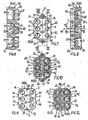
Anhand von bevorzugten, in der Zeichnung veranschaulichten Ausführungsbeispielen soll die Erfindung genauer erläutert werden. Dabei zeigen:
- Fig. 1
- eine Ansicht auf eine Seite einer Montagewandung in einer Einbausituation mit zwei neben- bzw. übereinander angeordneten, erfindungsgemäßen Kupplungseinrichtungen (Ansicht in Pfeilrichtung I gemäß
Fig. 2 ), - Fig. 2
- einen Schnitt senkrecht zur Montagewandung längs der Schnittlinie II-II in
Fig. 1 , - Fig. 3
- eine Ansicht auf die andere Seite der Anordnung nach
Fig. 1 und 2 in Pfeilrichtung III gemäßFig. 2 , - Fig. 4 bis 6
- jeweils einen vergrößerten Ausschnitt eines Teilbereichs einer erfindungsgemäßen Kupplungseinrichtung im Axialschnitt im Bereich einer aus einem Steckerteil und einem Muffenteil bestehenden Steckkupplung, und zwar
Fig.4 den (noch) nicht montierten Zustand (Explosionsdarstellung) der Komponenten in lagerichtiger Zuordnung vor bzw. nach der Montage,
Fig. 5 einen Vor- bzw. Zwischenmontagezustand der Komponenten sowie
Fig. 6 den fertig montierten und gekuppelten Zustand der erfindungsgemäßen Kupplungseinrichtung, - Fig. 7
- eine Ansicht auf die Rückseite eines erfindungsgemäßen Kupplungsteils ohne Steckkupplungsteile,
- Fig. 8
- einen vergrößerten Schnitt in der Ebene VIII-VIII gemäß
Fig. 7 , - Fig. 9
- einen entsprechend vergrößerten Schnitt in der Ebene IX-IX gemäß
Fig. 7 , - Fig. 10
- eine Ansicht auf die Kupplungsseite des Kupplungsteils gemäß
Fig. 7 , - Fig. 11 und 12
- Darstellungen analog zu
Fig. 7 und 10 einer vorteilhaften Ausführungsvariante des Kupplungsteils, - Fig. 13 bis 15
- vergrößerte Darstellungen analog zu
Fig. 11 zur Erläuterung von Ausführungsmöglichkeiten bezüglich der Verteilung von Stecker- und Muffen-Aufnahmeöffnungen des erfindungsgemäßen Kupplungsteils, - Fig. 16
- Schnittanssichten von
- a) Muffenteil und
- b) Steckerteil
in einer bevorzugten Ausgestaltung und
- Fig. 17
- eine alternative Ausgestaltung des Kupplungsteils in Ansichten analog zu
Fig. 11 und 12 , und zwar- a) Ansicht der Rückseite und
- b) Ansicht der Kupplungsseite.
- Fig. 1
- a view on one side of a mounting wall in a mounting situation with two side by side or one above the other arranged, coupling devices according to the invention (view in the direction of arrow I according to
Fig. 2 ) - Fig. 2
- a section perpendicular to the mounting wall along the section line II-II in
Fig. 1 . - Fig. 3
- a view on the other side of the arrangement
Fig. 1 and 2 in the direction of arrow III in accordance withFig. 2 . - 4 to 6
- in each case an enlarged section of a portion of a coupling device according to the invention in axial section in the region of a plug-in part consisting of a plug part and a socket part, namely
4 shows the (not yet) mounted state (exploded view) of the components in the correct position before or after assembly, FIG.
Fig. 5 shows a pre-or intermediate mounting state of the components and
6 shows the assembled and coupled state of the coupling device according to the invention, - Fig. 7
- a view of the back of a coupling part according to the invention without plug-in coupling parts,
- Fig. 8
- an enlarged section in the plane VIII-VIII according to
Fig. 7 . - Fig. 9
- a correspondingly enlarged section in the plane IX-IX according to
Fig. 7 . - Fig. 10
- a view on the coupling side of the coupling part according to
Fig. 7 . - FIGS. 11 and 12
- Representations analogous to
FIGS. 7 and 10 an advantageous embodiment of the coupling part, - Fig. 13 to 15
- enlarged views analogous to
Fig. 11 to explain embodiments with respect to the distribution of male and female receiving openings of the coupling part according to the invention, - Fig. 16
- Section views of
- a) socket part and
- b) plug part
in a preferred embodiment and
- Fig. 17
- an alternative embodiment of the coupling part in views analogous to
FIGS. 11 and 12 , in fact- a) view of the back and
- b) view of the coupling side.
In den verschiedenen Figuren der Zeichnung sind gleiche Teile stets mit den gleichen Bezugszeichen versehen, so dass jede eventuell nur einmal unter Bezugnahme auf eine der Zeichnungsfiguren vorkommende Beschreibung eines Teils analog auch bezüglich der anderen Zeichnungsfiguren gilt, in denen dieses Teil mit dem entsprechenden Bezugszeichen ebenfalls zu erkennen ist.In the various figures of the drawing, like parts are always provided with the same reference numerals, so that each possibly only once with reference to one of the drawing figures occurring description of a part analogously with respect to the other drawing figures, in which this part is also recognizable by the corresponding reference numeral.
Eine erfindungsgemäße Kupplungseinrichtung 1 ist für eine geradzahlige Anzahl von mindestens zwei, wie dargestellt bevorzugt sechs, Steckkupplungen 2 vorgesehen, die jeweils aus zwei Steckkupplungsteilen, und zwar einem Steckerteil 4 und einem Muffenteil 6, bestehen. Wie sich vor allem aus
Jedes Steckerteil 4 besitzt an seinem von dem Steckerschaft 8 abgekehrten Ende einen insbesondere als üblicher Einschlagdorn ausgebildeten Anschlussstutzen 14, und jedes Muffenteil 6 weist einen von der Steckaufnahme 12 axial abgekehrten, ebenfalls vorzugsweise als Einschlagdom ausgebildeten Anschlussstutzen 16 auf. Diese Anschlussstutzen 14, 16 dienen zum Anschluss von nicht dargestellten Medien-Leitungen, insbesondere von Kunststoff-Rohrleitungen (vorzugsweise aus PA), indem jede Leitung auf einen der Anschlussstutzen 14, 16 aufgesteckt wird.Each
Die Kupplungseinrichtung 1 besitzt ferner zwei im Wesentlichen plattenförmige Kupplungsteile 18, 20 zur Halterung und Arretierung der Steckkupplungsteile 4, 6 der Steckkupplungen 2. Im Bereich jeder Steckkupplung 2 weist das eine Kupplungsteil (z. B. 18) eine Aufnahmeöffnung S für das Steckerteil 4 auf, während das andere Kupplungsteil (z. B. 20) eine Aufnahmeöffnung M für das zugehörige Muffenteil 6 aufweist (siehe
Die Muffenteil-Aufnahmeöffnungen M besitzen verständlicherweise einen größeren Öffnungsquerschnitt als die Steckerteil-Aufnahmeöffnungen S. Zudem unterscheiden sich die Aufnahmeöffnungen S, M geringfügig bezüglich der Halterung der Stecker-und Muffenteile 4, 6. Dies wird weiter unten noch genauer erläutert werden.The female part receiving openings M understandably have a larger opening cross-section than the male part receiving openings S. In addition, the receiving openings S, M differ slightly with respect to the mounting of the male and
Erfindungsgemäß ist nun vorgesehen, dass die beiden Kupplungsteile 18 und 20 zumindest nahezu identisch insbesondere als jeweils einstückige, monolithische Kunststoff-Formteile ausgebildet sind. Durch die weitgehende Identität ist vorteilhafterweise eine Herstellung in ein und dem selben Formwerkzeug möglich. Zweckmäßig bestehen die Kupplungsteile 18, 20 aus einem faserverstärkten Kunststoffmaterial, beispielsweise PA66-GF30.According to the invention, it is now provided that the two
Jedes der im Wesentlichen identischen Kupplungsteile 18, 20 weist sowohl eine bestimmte Anzahl - wie dargestellt beispielsweise drei - von Aufnahmeöffnungen S für Steckerteile 4 als auch die gleiche Anzahl von Aufnahmeöffnungen M für Muffenteile 6 auf. Dabei sind bei jedem Kupplungsteil 18 bzw. 20 die beiden Arten der Aufnahmeöffnungen S und M jeweils paarweise symmetrisch gegenüberliegend zu einer Symmetrieachse X angeordnet. Hierdurch können die Kupplungsteile 18 und 20 aus einer gleichen Ausgangslage im Raum durch Drehen eines der Kupplungsteile um 180° um die Symmetrieachse X relativ zum anderen Kupplungsteil zwecks Kuppeln der Steckkupplungen 2 bzw. der Stecker- und Muffenteile 4, 6 verbunden werden. Es sei bemerkt, dass für die Funktionsfähigkeit der Kupplungseinrichtung 1 nicht alle vorhandenen Aufnahmeöffnungen S, M mit Steckerteilen 4 bzw. Muffenteilen 6 bestückt sein müssen; es reicht aus, wenn eines der Kupplungsteile (mindestens) ein Steckerteil 4 und das andere Kupplungsteil (zumindest) in der zugeordneten Aufnahmeöffnung M ein Muffenteil 6 aufweiset.Each of the substantially
Aus der erfindungsgemäßen Ausgestaltung mit der symmetrischen Anordnung der Aufnahmeöffnungen S und M resultiert der weitere wichtige Vorteil, dass die Kupplungsteile 18, 20 nur in einer Relativstellung miteinander kuppelbar sind. Beim Anschluss können folglich die einander zugeordneten Stecker- und Muffenteile 4, 6 nicht vertauscht werden (selbsttätiger Vertauschungsschutz).From the embodiment according to the invention with the symmetrical arrangement of the receiving openings S and M results in the further important advantage that the
Für die Anordnung bzw. Verteilung der beiden Arten der Aufnahmeöffnungen S und M auf der Fläche des jeweiligen Kupplungsteils 18, 20 gibt es verschiedene Möglichkeiten. Gemäß
In der in
Zur Befestigung im Bereich einer entsprechend groß ausgelegten Leitungs-Durchführöffnung einer Montagewandung 30 (sog. Schottwand, siehe
In den dargestellten Ausführungsbeispielen weist jedes Kupplungsteil 18, 20 eine im Wesentlichen rechteckige Flächenform mit vorzugsweise abgerundeten Ecken auf. Dabei ist in den Ausführungen gemäß
Bei beiden Ausführungen wird durch die Anordnung der Montagelöcher 34 auf der Symmetrieachse X der Vorteil erreicht, dass die Reihenfolge der Montage beliebig ist, d. h. es ist unerheblich, ob das Kupplungsteil 18 oder das Kupplungsteil 20 auf der jeweiligen Seite der Montagewandung 30 befestigt wird.In both embodiments, the arrangement of the mounting holes 34 on the axis of symmetry X achieves the advantage that the sequence of assembly is arbitrary, ie, it is irrelevant whether the
Da alle genannten Schraubverbindungen auf oder in der Nähe der Symmetrieachse X angeordnet sind, ist es vorteilhaft, wenn jedes Kupplungsteil 18 oder 20 mindestens zwei bezüglich der Symmetrieachse X gegenüberliegende, randliche Anlageelemente 46 zur kippverhindemden Anlage an der Montagewandung 30 aufweist. Wie dargestellt können insgesamt vier Anlageelemente 46 in paarweiser Anordnung auf beiden Längsseiten jedes Kupplungsteils 18, 20 vorgesehen sein.Since all the above-mentioned screw connections are arranged on or in the vicinity of the axis of symmetry X, it is advantageous if each
Bevorzugt wird jedes Steckkupplungsteil 4, 6 über derart ausgebildete Rastmittel 50 (nur in
Im dargestellten, besonders vorteilhaften Ausführungsbeispiel weist jedes Kupplungsteil 18, 20 als Rastmittel 50 radial federelastische Rastarme 56 bzw. 58 auf, die jweils über den Umfang der Aufnahmeöffnung S bzw. M verteilt angeordnet sind (und so praktisch die jeweiligen Aufnahmeöffnung bilden) und sich dabei jeweils ausgehend von der Rückseite 52 bzw. 54 des Kupplungsteils 18 bzw. 20 im Wesentlichen in bzw. parallel zur Fügerichtung der Steckkupplungen 2 erstrecken. Hierbei besitzen die Rastarme 56, 58 in ihrem zur Kupplungsseite 60 bzw. 62 des jeweiligen Kupplungsteils 18, 20 weisenden, in radialer Richtung federelastisch beweglichen Bereich radial nach innen in die Aufnahmeöffnung S bzw. M ragende Rastansätze 64, die jeweils mit einer umfänglichen Ringnut 66 des jeweiligen Steckkupplungsteils 4 bzw. 6 rastend zusammenwirken. Hierbei ist ferner vorgesehen, dass die Rastarme 58 im Bereich jeder Muffelteil-Aufnahmeöffnung M in Fügerichtung weisende Sperransätze 68 aufweisen, die im miteinander verbundenen Zustand der Kupplungsteile 18, 20 in axialer Richtung in einen die Rastarme 56 des anderen Kupplungsteils umschließenden Ringspalt 70 derart eingreifen, dass dann alle Rastarme 56, 58 beider Kupplungsteile 18, 20 gegen eine radiale Bewegung abgestützt (gesperrt) sind. Dies läßt sich in
Insbesondere bei Anwendungen in Fahrzeugen ist es zudem vorteilhaft, wenn die Steckkupplungsteile 4, 6 in der jeweiligen Aufnahmeöffnung S, M umfänglich abgedichtet sind. Wie in
Wie sich noch aus
Wie sich weiter aus
In diesem Zusammenhang sind die Anschlagelemente 74 der Stecker-und Muffenteile 4, 6 von besonderem Vorteil, weil dadurch sicher verhindert wird, dass sie über ihre eigentliche Raststellung hinausgehend eingesetzt werden können, wodurch die Rastarme 56 ,58 wieder gespreizt werden würden und dadurch die Kupplungsteile 18, 20 nur schwer oder gar nicht mehr gekuppelt werden könnten. Ohne die Anschlagelemente 74 wäre diese Gefahr durch den kleineren Winkel α1 besonders groß. Durch den größeren Winkel α2, der bis zu 90° (Formschluß = unlösbar) betragen kann, wird verhindert, dass beim Kuppeln durch vormontierte Leitungen die Steckkupplungsteile 4, 6 aus dem jeweiligen Kupplungseil 18, 20 herausgezogen bzw. herausgedrückt werden könnten.In this context, the
Claims (19)
- A coupling device (1) for hose lines and/or pipelines, in particular for wall ducts of fluid lines, having two plate-like coupling parts (18, 20) which can be connected to one another and which each have receiving openings (S, M) for the insertion and fixed securing of plug-in coupling parts, namely plug parts (4) on the one hand and socket parts (6) on the other hand, in such a manner that, through connection of the coupling parts (18, 20), the plug parts and socket parts (4, 6) are inserted into one another in pairs in a joining direction, wherein each plug-in coupling part (4, 6) can be fixed in the associated receiving opening (S, M) of the respective coupling part (18, 20) via locking means (50) designed in such a manner that the plug-in coupling part is on the one hand insertable into the corresponding receiving opening (S, M) of the respective coupling part (18, 20) in a locking and detachable manner when the coupling parts (18, 20) are separated and on the other hand is held undetachably through automatic mutual blocking of the locking means (50) when the coupling parts (18, 20) are in the connected state, wherein the receiving openings (S) for the plug parts and the receiving openings (M) for the socket parts differ in construction, characterised in that the two coupling parts (18, 20) are in the form of substantially identical moulded parts, in that the two coupling parts (18, 20) are identical in design with regard to the arrangement of the receiving openings (S, M) for the plug part and the socket part, wherein each coupling part (18, 20) has both at least one receiving opening (S) for a plug part (4) and at least one receiving opening (M) for a socket part (6), wherein the two types of receiving openings (S, M) are arranged in pairs mirror-symmetrically with respect to an axis of symmetry (X).
- A coupling device according to claim 1, characterised in that each coupling part (18, 20) is in the form of a one-piece, monolithic plastics moulded part.
- A coupling device according to claim 1 or 2, characterised in that each coupling part (18, 20) has, for mutual connection to the other coupling part (20, 18) in each case, at least one through hole (22) and at least one screw hole (24) in a symmetrical arrangement to one another with respect to the axis of symmetry (X).
- A coupling device according to claim 3, characterised in that the/each screw hole (24) is designed in such a manner that in each case a self-tapping screw (28) can be screwed through the through hole (22) of one coupling part (18, 20) directly into the screw hole (24) of the other coupling part (20, 18).
- A coupling device according to any one of claims 1 to 4, characterised in that each coupling part (18, 20) has, for fixing to an installation wall (30), at least two securing portions (32) with installation holes (34) which are preferably located on the axis of symmetry (X).
- A coupling device according to claim 5, characterised in that the installation holes (34) are designed for the direct screwing-in of self-tapping screws (36).
- A coupling device according to claim 5 or 6, characterised in that each securing portion (32) has a wall contact surface (38) which is offset in relation to a coupling plane (40), located between the connected coupling parts (18, 20), in such a manner that sufficient free space (42) to receive a holding portion of the installation wall (30) and, optionally, a screw head of the screw (36) is formed between the securing portions (32) of the two connected coupling parts (18, 20).
- A coupling device according to any one of claims 5 to 7, characterised in that each coupling part (18, 20) has a given, in particular substantially rectangular, surface shape, wherein the securing portions (32) are formed as lugs protruding beyond the surface shape or as partial regions within the surface shape.
- A coupling device according to any one of claims 1 to 8, characterised in that each coupling part (18, 20) has at least two contact elements (46), located opposite each other with respect to the axis of symmetry (X), to contact with the installation wall (30).
- A coupling device according to any one of claims 1 to 9, characterised in that the coupling parts (18, 20) have, as locking means (50), radially resilient locking arms (56, 58) which are each arranged so as to be distributed over the circumference of the receiving opening (S, M) and extend substantially in the joining direction of the plug-in coupling parts (4, 6).
- A coupling device according to claim 10, characterised in that in their region directed towards the coupling side (60, 62) of the respective coupling part (18, 20), the locking arms (56, 58) have locking lugs (64) which project radially inwards into the receiving opening (S, M) and which cooperate in a locking manner with an annular groove (66) of the respective plug-in coupling part (4, 6).
- A coupling device according to claim 10 or 11, characterised in that the locking arms (58), in particular of each socket-receiving opening (M), have blocking lugs (68) which are directed in the joining direction and which, in the connected state of the coupling parts (18, 20), engage a respective annular gap (70) surrounding the locking arms (56), in particular of each plug-receiving opening (S), in such a manner that all locking arms (56, 58) of both coupling parts (18, 20) are blocked as regards radial movement.
- A coupling device according to any one of claims 1 to 12 having plug-in coupling parts (4, 6) arranged in the receiving openings (S, M), characterised in that each plug-in coupling part (4, 6) has a stop element (74) for insertion-limiting contact with the respective coupling part (18, 20).
- A coupling device according to any one of claims 11 to 13, characterised in that the annular groove (66) of each plug-in coupling part (4, 6) and each locking lug (64) of the locking arms (56, 58) of the coupling parts (18, 20) have on the one hand, on their sides cooperating in the insertion direction, first oblique surfaces (76) and on the other hand, on their sides cooperating in the removal direction, second oblique surfaces (78), wherein the first oblique surfaces (76) and the second oblique surfaces (78) form a first angle (α1) and a second angle (α2) respectively with the plug-in axis (80).
- A coupling device according to claim 14, characterised in that the first angle (α1) is smaller than the second angle (α2).
- A coupling device according to claim 14 or 15, characterised in that the first angle (α1) lies in the range of 15° to 60°, in particular 30° to 45°, and the second angle (α2) lies in the range of 30° to 90°, in particular 45° to 60°.
- A coupling device according to any one of claims 1 to 16 having plug-in coupling parts (4, 6) arranged in the receiving openings (S, M), characterised in that the plug-in coupling parts (4, 6) each have a connection piece (14, 16), in particular a drive-in pin for the attachment of a line, in particular of a plastics pipe.
- A coupling part (18, 20) for a coupling device (1) according to any one of claims 1 to 17, having at least two receiving openings (S/M) for the insertion and fixed securing of plug-in coupling parts (4, 6), wherein each plug-in coupling part (4, 6) can be fixed in the associated receiving opening (S/M) via locking means (50), characterised by at least one receiving opening (S) for a plug part (4) as well as at least one receiving opening (M) for a socket part (6), wherein the two differently designed types of receiving openings (S, M) are arranged opposite each other in pairs mirror-symmetrically with respect to an axis of symmetry (X).
- A coupling part according to claim 18, characterised by at least one additional feature, relating to the coupling part (18/20), of one of claims 2 to 16.
Applications Claiming Priority (2)
| Application Number | Priority Date | Filing Date | Title |
|---|---|---|---|
| DE202005001153U DE202005001153U1 (en) | 2005-01-24 | 2005-01-24 | Coupling device for media lines |
| PCT/EP2006/050413 WO2006077264A1 (en) | 2005-01-24 | 2006-01-24 | Coupling device for media conduits |
Publications (2)
| Publication Number | Publication Date |
|---|---|
| EP1841995A1 EP1841995A1 (en) | 2007-10-10 |
| EP1841995B1 true EP1841995B1 (en) | 2010-06-02 |
Family
ID=36130151
Family Applications (1)
| Application Number | Title | Priority Date | Filing Date |
|---|---|---|---|
| EP06704248A Not-in-force EP1841995B1 (en) | 2005-01-24 | 2006-01-24 | Coupling device for media conduits |
Country Status (6)
| Country | Link |
|---|---|
| US (1) | US8256801B2 (en) |
| EP (1) | EP1841995B1 (en) |
| CN (1) | CN101147019B (en) |
| AT (1) | ATE470098T1 (en) |
| DE (2) | DE202005001153U1 (en) |
| WO (1) | WO2006077264A1 (en) |
Cited By (1)
| Publication number | Priority date | Publication date | Assignee | Title |
|---|---|---|---|---|
| DE102012110935A1 (en) | 2012-11-14 | 2014-05-15 | Voss Automotive Gmbh | Coupling device for media lines |
Families Citing this family (12)
| Publication number | Priority date | Publication date | Assignee | Title |
|---|---|---|---|---|
| DE202008002206U1 (en) * | 2008-02-15 | 2009-06-25 | Voss Automotive Gmbh | Multiple plug-in coupling for media lines |
| JP5447975B2 (en) * | 2010-06-29 | 2014-03-19 | 住友電装株式会社 | Gas distribution unit |
| DE102012202142B4 (en) * | 2012-02-13 | 2024-01-18 | Schaeffler Technologies AG & Co. KG | fastener |
| DE102012004165A1 (en) | 2012-03-05 | 2013-09-05 | Voss Automotive Gmbh | Control system and method for controlling the assembly of a coupling device |
| DE102013214611A1 (en) * | 2013-07-26 | 2015-01-29 | Bayerische Motoren Werke Aktiengesellschaft | Coupling system for forming at least one arranged in a vehicle fluid-carrying line |
| ES2601225T3 (en) * | 2013-12-10 | 2017-02-14 | Faster S.P.A. | Multi-connector device for quick multiple connection of multiple hydraulic, electric and / or pneumatic lines, with the possibility of individual manual connectors |
| US10763189B2 (en) * | 2014-08-29 | 2020-09-01 | International Business Machines Corporation | Sealing arrangement |
| PL3061890T3 (en) * | 2015-02-26 | 2018-02-28 | Hauff-Technik Gmbh & Co. Kg | Feed-through for casting with concrete |
| DE102017106676A1 (en) * | 2017-03-28 | 2018-10-04 | Voss Automotive Gmbh | Connecting device for media lines |
| DE102017126477A1 (en) * | 2017-11-10 | 2019-05-16 | Syn Trac Gmbh | clutch plate |
| DE102022112773A1 (en) | 2022-05-20 | 2023-11-23 | Johannes Schäfer vorm. Stettiner Schraubenwerke GmbH & Co. KG | Plastic component with a plug-in part and a cavity intended to accommodate a fastener |
| DE102022122296A1 (en) * | 2022-09-02 | 2024-03-07 | Voss Automotive Gmbh | Multiple coupling for media lines and coupling carriers |
Family Cites Families (15)
| Publication number | Priority date | Publication date | Assignee | Title |
|---|---|---|---|---|
| US1899861A (en) * | 1930-03-20 | 1933-02-28 | American Conduit Corp | Tile |
| US1974402A (en) * | 1931-01-31 | 1934-09-18 | John O Templeton | Heat exchanger |
| US2628850A (en) * | 1949-03-19 | 1953-02-17 | Donald V Summerville | Releasable conduit connection with automatic valving |
| US3469863A (en) * | 1967-04-05 | 1969-09-30 | Trico Products Corp | Fluid coupling assembly |
| GB1216767A (en) * | 1968-04-18 | 1970-12-23 | Carl Kurt Walther | Device for the simultaneous coupling of a plurality of separate hose-pipes |
| FR2122738A5 (en) * | 1971-01-21 | 1972-09-01 | Corobit Anstalt | |
| US3779584A (en) * | 1971-09-22 | 1973-12-18 | Pitney Bowes Inc | Fluidic connector |
| US4555130A (en) * | 1983-04-01 | 1985-11-26 | The United States Of America As Represented By The Secretary Of The Navy | Diver's umbilical quick-disconnect device |
| US4884584A (en) * | 1987-08-14 | 1989-12-05 | National Coupling Company, Inc. | Internally preloaded metal-to-metal seal hydraulic connector |
| US4982736A (en) * | 1989-02-08 | 1991-01-08 | Hollister Incorporated | Hermaphroditic coupling for anatomical thermal system |
| DE8904141U1 (en) * | 1989-04-04 | 1989-05-24 | Rectus-Apparatebau Walter Klein Gmbh, 7147 Eberdingen, De | |
| DE4310370A1 (en) | 1993-03-30 | 1994-10-06 | Voss Armaturen | Coupling device for hose and / or pipes |
| US5645302A (en) * | 1994-04-27 | 1997-07-08 | Sakura Rubber Co., Ltd. | Coupling apparatus |
| AU2002306482A1 (en) * | 2001-02-13 | 2002-08-28 | Smc Corporation Of America | Pneumatic coupling |
| US7021668B2 (en) * | 2004-02-06 | 2006-04-04 | Westendorf Manufacturing Co., Inc. | Hydraulic line attachment device and method |
-
2005
- 2005-01-24 DE DE202005001153U patent/DE202005001153U1/en not_active Expired - Lifetime
-
2006
- 2006-01-24 CN CN2006800090800A patent/CN101147019B/en not_active Expired - Fee Related
- 2006-01-24 AT AT06704248T patent/ATE470098T1/en not_active IP Right Cessation
- 2006-01-24 DE DE502006007085T patent/DE502006007085D1/en active Active
- 2006-01-24 WO PCT/EP2006/050413 patent/WO2006077264A1/en active Application Filing
- 2006-01-24 EP EP06704248A patent/EP1841995B1/en not_active Not-in-force
-
2007
- 2007-07-24 US US11/782,471 patent/US8256801B2/en not_active Expired - Fee Related
Cited By (2)
| Publication number | Priority date | Publication date | Assignee | Title |
|---|---|---|---|---|
| DE102012110935A1 (en) | 2012-11-14 | 2014-05-15 | Voss Automotive Gmbh | Coupling device for media lines |
| EP2733403A1 (en) | 2012-11-14 | 2014-05-21 | Voss Automotive GmbH | Coupling device for media conduits |
Also Published As
| Publication number | Publication date |
|---|---|
| CN101147019B (en) | 2012-10-03 |
| US8256801B2 (en) | 2012-09-04 |
| WO2006077264A1 (en) | 2006-07-27 |
| DE502006007085D1 (en) | 2010-07-15 |
| EP1841995A1 (en) | 2007-10-10 |
| CN101147019A (en) | 2008-03-19 |
| US20080014774A1 (en) | 2008-01-17 |
| ATE470098T1 (en) | 2010-06-15 |
| DE202005001153U1 (en) | 2006-06-08 |
Similar Documents
| Publication | Publication Date | Title |
|---|---|---|
| EP1841995B1 (en) | Coupling device for media conduits | |
| EP3149384B1 (en) | Plug-in connector for fluid lines with inner adapter sleeve | |
| EP1697674B1 (en) | Plug connector for fluid conduits | |
| EP2439439B1 (en) | Connecting element for a fluid connection | |
| WO2006039882A1 (en) | Joining arrangement for connecting a pipe to a system | |
| EP1733164B1 (en) | Plug-in connection provided with an angle-locking device | |
| EP2419978A2 (en) | Cable guide | |
| EP2990708B1 (en) | Coupling system for connecting two fluid conducting elements | |
| EP4127543B1 (en) | Plug-type coupling with pre-assembly locking | |
| DE102005044304A1 (en) | Connector for attaching pipes to hydraulic decoupling systems has annular groove on its inner surface which fits over collar on pipe | |
| DE60205641T2 (en) | CLUTCH AND ASSEMBLY PROCESS USED TO CONNECT TWO TUBE ELEMENTS | |
| EP1352193A1 (en) | Locking plug-in connection device | |
| EP2115825B1 (en) | Electrical connector | |
| EP2733403B1 (en) | Coupling device for media conduits | |
| EP1731821A2 (en) | Quick-acting coupling for a pipe system | |
| EP3601867A1 (en) | Connecting device for media lines | |
| EP2369215B1 (en) | Connector | |
| EP0618393B1 (en) | Coupling device for hoses and/or circuits | |
| EP1801485B1 (en) | Coupling device for interconnecting multiple fluid lines | |
| DE202011103941U1 (en) | pipe connectors | |
| EP3526507B1 (en) | Connector and connector assembly and method for producing a connector | |
| DE4310795C1 (en) | Plug-in type union between pipes | |
| EP1703192B1 (en) | Bayonet coupling | |
| DE102007023987A1 (en) | Multiple coupler for hydraulic and pneumatic flow medium and/or pressure medium, has holding unit with clamping unit for surrounding projections with sections, where projections lie axially adjacent to each other in coupling position | |
| DE4022769C2 (en) | Pipe multiple coupling |
Legal Events
| Date | Code | Title | Description |
|---|---|---|---|
| PUAI | Public reference made under article 153(3) epc to a published international application that has entered the european phase |
Free format text: ORIGINAL CODE: 0009012 |
|
| 17P | Request for examination filed |
Effective date: 20060623 |
|
| AK | Designated contracting states |
Kind code of ref document: A1 Designated state(s): AT BE BG CH CY CZ DE DK EE ES FI FR GB GR HU IE IS IT LI LT LU LV MC NL PL PT RO SE SI SK TR |
|
| DAX | Request for extension of the european patent (deleted) | ||
| 17Q | First examination report despatched |
Effective date: 20080523 |
|
| GRAP | Despatch of communication of intention to grant a patent |
Free format text: ORIGINAL CODE: EPIDOSNIGR1 |
|
| GRAS | Grant fee paid |
Free format text: ORIGINAL CODE: EPIDOSNIGR3 |
|
| GRAA | (expected) grant |
Free format text: ORIGINAL CODE: 0009210 |
|
| AK | Designated contracting states |
Kind code of ref document: B1 Designated state(s): AT BE BG CH CY CZ DE DK EE ES FI FR GB GR HU IE IS IT LI LT LU LV MC NL PL PT RO SE SI SK TR |
|
| REG | Reference to a national code |
Ref country code: GB Ref legal event code: FG4D Free format text: NOT ENGLISH |
|
| REG | Reference to a national code |
Ref country code: CH Ref legal event code: EP |
|
| REG | Reference to a national code |
Ref country code: IE Ref legal event code: FG4D Free format text: LANGUAGE OF EP DOCUMENT: GERMAN |
|
| REF | Corresponds to: |
Ref document number: 502006007085 Country of ref document: DE Date of ref document: 20100715 Kind code of ref document: P |
|
| REG | Reference to a national code |
Ref country code: SE Ref legal event code: TRGR |
|
| REG | Reference to a national code |
Ref country code: NL Ref legal event code: VDEP Effective date: 20100602 |
|
| PG25 | Lapsed in a contracting state [announced via postgrant information from national office to epo] |
Ref country code: LT Free format text: LAPSE BECAUSE OF FAILURE TO SUBMIT A TRANSLATION OF THE DESCRIPTION OR TO PAY THE FEE WITHIN THE PRESCRIBED TIME-LIMIT Effective date: 20100602 |
|
| LTIE | Lt: invalidation of european patent or patent extension |
Effective date: 20100602 |
|
| PG25 | Lapsed in a contracting state [announced via postgrant information from national office to epo] |
Ref country code: FI Free format text: LAPSE BECAUSE OF FAILURE TO SUBMIT A TRANSLATION OF THE DESCRIPTION OR TO PAY THE FEE WITHIN THE PRESCRIBED TIME-LIMIT Effective date: 20100602 Ref country code: SI Free format text: LAPSE BECAUSE OF FAILURE TO SUBMIT A TRANSLATION OF THE DESCRIPTION OR TO PAY THE FEE WITHIN THE PRESCRIBED TIME-LIMIT Effective date: 20100602 Ref country code: LV Free format text: LAPSE BECAUSE OF FAILURE TO SUBMIT A TRANSLATION OF THE DESCRIPTION OR TO PAY THE FEE WITHIN THE PRESCRIBED TIME-LIMIT Effective date: 20100602 |
|
| PG25 | Lapsed in a contracting state [announced via postgrant information from national office to epo] |
Ref country code: GR Free format text: LAPSE BECAUSE OF FAILURE TO SUBMIT A TRANSLATION OF THE DESCRIPTION OR TO PAY THE FEE WITHIN THE PRESCRIBED TIME-LIMIT Effective date: 20100903 Ref country code: CY Free format text: LAPSE BECAUSE OF FAILURE TO SUBMIT A TRANSLATION OF THE DESCRIPTION OR TO PAY THE FEE WITHIN THE PRESCRIBED TIME-LIMIT Effective date: 20100602 Ref country code: PL Free format text: LAPSE BECAUSE OF FAILURE TO SUBMIT A TRANSLATION OF THE DESCRIPTION OR TO PAY THE FEE WITHIN THE PRESCRIBED TIME-LIMIT Effective date: 20100602 |
|
| REG | Reference to a national code |
Ref country code: IE Ref legal event code: FD4D |
|
| PG25 | Lapsed in a contracting state [announced via postgrant information from national office to epo] |
Ref country code: NL Free format text: LAPSE BECAUSE OF FAILURE TO SUBMIT A TRANSLATION OF THE DESCRIPTION OR TO PAY THE FEE WITHIN THE PRESCRIBED TIME-LIMIT Effective date: 20100602 Ref country code: IE Free format text: LAPSE BECAUSE OF FAILURE TO SUBMIT A TRANSLATION OF THE DESCRIPTION OR TO PAY THE FEE WITHIN THE PRESCRIBED TIME-LIMIT Effective date: 20100602 Ref country code: EE Free format text: LAPSE BECAUSE OF FAILURE TO SUBMIT A TRANSLATION OF THE DESCRIPTION OR TO PAY THE FEE WITHIN THE PRESCRIBED TIME-LIMIT Effective date: 20100602 |
|
| PG25 | Lapsed in a contracting state [announced via postgrant information from national office to epo] |
Ref country code: PT Free format text: LAPSE BECAUSE OF FAILURE TO SUBMIT A TRANSLATION OF THE DESCRIPTION OR TO PAY THE FEE WITHIN THE PRESCRIBED TIME-LIMIT Effective date: 20101004 Ref country code: RO Free format text: LAPSE BECAUSE OF FAILURE TO SUBMIT A TRANSLATION OF THE DESCRIPTION OR TO PAY THE FEE WITHIN THE PRESCRIBED TIME-LIMIT Effective date: 20100602 Ref country code: IS Free format text: LAPSE BECAUSE OF FAILURE TO SUBMIT A TRANSLATION OF THE DESCRIPTION OR TO PAY THE FEE WITHIN THE PRESCRIBED TIME-LIMIT Effective date: 20101002 Ref country code: CZ Free format text: LAPSE BECAUSE OF FAILURE TO SUBMIT A TRANSLATION OF THE DESCRIPTION OR TO PAY THE FEE WITHIN THE PRESCRIBED TIME-LIMIT Effective date: 20100602 Ref country code: SK Free format text: LAPSE BECAUSE OF FAILURE TO SUBMIT A TRANSLATION OF THE DESCRIPTION OR TO PAY THE FEE WITHIN THE PRESCRIBED TIME-LIMIT Effective date: 20100602 |
|
| PG25 | Lapsed in a contracting state [announced via postgrant information from national office to epo] |
Ref country code: IT Free format text: LAPSE BECAUSE OF FAILURE TO SUBMIT A TRANSLATION OF THE DESCRIPTION OR TO PAY THE FEE WITHIN THE PRESCRIBED TIME-LIMIT Effective date: 20100602 |
|
| PLBE | No opposition filed within time limit |
Free format text: ORIGINAL CODE: 0009261 |
|
| STAA | Information on the status of an ep patent application or granted ep patent |
Free format text: STATUS: NO OPPOSITION FILED WITHIN TIME LIMIT |
|
| PG25 | Lapsed in a contracting state [announced via postgrant information from national office to epo] |
Ref country code: DK Free format text: LAPSE BECAUSE OF FAILURE TO SUBMIT A TRANSLATION OF THE DESCRIPTION OR TO PAY THE FEE WITHIN THE PRESCRIBED TIME-LIMIT Effective date: 20100602 |
|
| 26N | No opposition filed |
Effective date: 20110303 |
|
| REG | Reference to a national code |
Ref country code: DE Ref legal event code: R097 Ref document number: 502006007085 Country of ref document: DE Effective date: 20110302 |
|
| BERE | Be: lapsed |
Owner name: VOSS AUTOMOTIVE G.M.B.H. Effective date: 20110131 |
|
| PG25 | Lapsed in a contracting state [announced via postgrant information from national office to epo] |
Ref country code: MC Free format text: LAPSE BECAUSE OF NON-PAYMENT OF DUE FEES Effective date: 20110131 |
|
| REG | Reference to a national code |
Ref country code: CH Ref legal event code: PL |
|
| GBPC | Gb: european patent ceased through non-payment of renewal fee |
Effective date: 20110124 |
|
| REG | Reference to a national code |
Ref country code: FR Ref legal event code: ST Effective date: 20110930 |
|
| PG25 | Lapsed in a contracting state [announced via postgrant information from national office to epo] |
Ref country code: LI Free format text: LAPSE BECAUSE OF NON-PAYMENT OF DUE FEES Effective date: 20110131 Ref country code: CH Free format text: LAPSE BECAUSE OF NON-PAYMENT OF DUE FEES Effective date: 20110131 Ref country code: FR Free format text: LAPSE BECAUSE OF NON-PAYMENT OF DUE FEES Effective date: 20110131 |
|
| PG25 | Lapsed in a contracting state [announced via postgrant information from national office to epo] |
Ref country code: GB Free format text: LAPSE BECAUSE OF NON-PAYMENT OF DUE FEES Effective date: 20110124 Ref country code: BE Free format text: LAPSE BECAUSE OF NON-PAYMENT OF DUE FEES Effective date: 20110131 |
|
| REG | Reference to a national code |
Ref country code: AT Ref legal event code: MM01 Ref document number: 470098 Country of ref document: AT Kind code of ref document: T Effective date: 20110124 |
|
| PG25 | Lapsed in a contracting state [announced via postgrant information from national office to epo] |
Ref country code: AT Free format text: LAPSE BECAUSE OF NON-PAYMENT OF DUE FEES Effective date: 20110124 |
|
| PG25 | Lapsed in a contracting state [announced via postgrant information from national office to epo] |
Ref country code: LU Free format text: LAPSE BECAUSE OF NON-PAYMENT OF DUE FEES Effective date: 20110124 |
|
| PG25 | Lapsed in a contracting state [announced via postgrant information from national office to epo] |
Ref country code: TR Free format text: LAPSE BECAUSE OF FAILURE TO SUBMIT A TRANSLATION OF THE DESCRIPTION OR TO PAY THE FEE WITHIN THE PRESCRIBED TIME-LIMIT Effective date: 20100602 Ref country code: BG Free format text: LAPSE BECAUSE OF FAILURE TO SUBMIT A TRANSLATION OF THE DESCRIPTION OR TO PAY THE FEE WITHIN THE PRESCRIBED TIME-LIMIT Effective date: 20100902 |
|
| PG25 | Lapsed in a contracting state [announced via postgrant information from national office to epo] |
Ref country code: HU Free format text: LAPSE BECAUSE OF FAILURE TO SUBMIT A TRANSLATION OF THE DESCRIPTION OR TO PAY THE FEE WITHIN THE PRESCRIBED TIME-LIMIT Effective date: 20100602 Ref country code: ES Free format text: LAPSE BECAUSE OF FAILURE TO SUBMIT A TRANSLATION OF THE DESCRIPTION OR TO PAY THE FEE WITHIN THE PRESCRIBED TIME-LIMIT Effective date: 20100913 |
|
| PGFP | Annual fee paid to national office [announced via postgrant information from national office to epo] |
Ref country code: DE Payment date: 20210330 Year of fee payment: 16 |
|
| PGFP | Annual fee paid to national office [announced via postgrant information from national office to epo] |
Ref country code: SE Payment date: 20211230 Year of fee payment: 17 |
|
| REG | Reference to a national code |
Ref country code: DE Ref legal event code: R119 Ref document number: 502006007085 Country of ref document: DE |
|
| PG25 | Lapsed in a contracting state [announced via postgrant information from national office to epo] |
Ref country code: DE Free format text: LAPSE BECAUSE OF NON-PAYMENT OF DUE FEES Effective date: 20220802 |
|
| REG | Reference to a national code |
Ref country code: SE Ref legal event code: EUG |
|
| PG25 | Lapsed in a contracting state [announced via postgrant information from national office to epo] |
Ref country code: SE Free format text: LAPSE BECAUSE OF NON-PAYMENT OF DUE FEES Effective date: 20230125 |