EP1840626A1 - Head-up display, motor vehicle und method for operating a head-up display - Google Patents
Head-up display, motor vehicle und method for operating a head-up display Download PDFInfo
- Publication number
- EP1840626A1 EP1840626A1 EP20070006337 EP07006337A EP1840626A1 EP 1840626 A1 EP1840626 A1 EP 1840626A1 EP 20070006337 EP20070006337 EP 20070006337 EP 07006337 A EP07006337 A EP 07006337A EP 1840626 A1 EP1840626 A1 EP 1840626A1
- Authority
- EP
- European Patent Office
- Prior art keywords
- display
- light
- color
- head
- light guide
- Prior art date
- Legal status (The legal status is an assumption and is not a legal conclusion. Google has not performed a legal analysis and makes no representation as to the accuracy of the status listed.)
- Granted
Links
Images


Classifications
-
- G—PHYSICS
- G02—OPTICS
- G02B—OPTICAL ELEMENTS, SYSTEMS OR APPARATUS
- G02B27/00—Optical systems or apparatus not provided for by any of the groups G02B1/00 - G02B26/00, G02B30/00
- G02B27/01—Head-up displays
- G02B27/0101—Head-up displays characterised by optical features
-
- G—PHYSICS
- G02—OPTICS
- G02B—OPTICAL ELEMENTS, SYSTEMS OR APPARATUS
- G02B6/00—Light guides; Structural details of arrangements comprising light guides and other optical elements, e.g. couplings
- G02B6/0001—Light guides; Structural details of arrangements comprising light guides and other optical elements, e.g. couplings specially adapted for lighting devices or systems
- G02B6/0011—Light guides; Structural details of arrangements comprising light guides and other optical elements, e.g. couplings specially adapted for lighting devices or systems the light guides being planar or of plate-like form
- G02B6/0033—Means for improving the coupling-out of light from the light guide
- G02B6/0058—Means for improving the coupling-out of light from the light guide varying in density, size, shape or depth along the light guide
- G02B6/006—Means for improving the coupling-out of light from the light guide varying in density, size, shape or depth along the light guide to produce indicia, symbols, texts or the like
-
- G—PHYSICS
- G02—OPTICS
- G02B—OPTICAL ELEMENTS, SYSTEMS OR APPARATUS
- G02B6/00—Light guides; Structural details of arrangements comprising light guides and other optical elements, e.g. couplings
- G02B6/0001—Light guides; Structural details of arrangements comprising light guides and other optical elements, e.g. couplings specially adapted for lighting devices or systems
- G02B6/0011—Light guides; Structural details of arrangements comprising light guides and other optical elements, e.g. couplings specially adapted for lighting devices or systems the light guides being planar or of plate-like form
- G02B6/0066—Light guides; Structural details of arrangements comprising light guides and other optical elements, e.g. couplings specially adapted for lighting devices or systems the light guides being planar or of plate-like form characterised by the light source being coupled to the light guide
- G02B6/0068—Arrangements of plural sources, e.g. multi-colour light sources
-
- G—PHYSICS
- G02—OPTICS
- G02B—OPTICAL ELEMENTS, SYSTEMS OR APPARATUS
- G02B6/00—Light guides; Structural details of arrangements comprising light guides and other optical elements, e.g. couplings
- G02B6/0001—Light guides; Structural details of arrangements comprising light guides and other optical elements, e.g. couplings specially adapted for lighting devices or systems
- G02B6/0011—Light guides; Structural details of arrangements comprising light guides and other optical elements, e.g. couplings specially adapted for lighting devices or systems the light guides being planar or of plate-like form
- G02B6/0075—Arrangements of multiple light guides
- G02B6/0078—Side-by-side arrangements, e.g. for large area displays
-
- G—PHYSICS
- G02—OPTICS
- G02B—OPTICAL ELEMENTS, SYSTEMS OR APPARATUS
- G02B27/00—Optical systems or apparatus not provided for by any of the groups G02B1/00 - G02B26/00, G02B30/00
- G02B27/01—Head-up displays
- G02B27/0101—Head-up displays characterised by optical features
- G02B2027/0112—Head-up displays characterised by optical features comprising device for genereting colour display
-
- G—PHYSICS
- G02—OPTICS
- G02B—OPTICAL ELEMENTS, SYSTEMS OR APPARATUS
- G02B6/00—Light guides; Structural details of arrangements comprising light guides and other optical elements, e.g. couplings
-
- G—PHYSICS
- G02—OPTICS
- G02F—OPTICAL DEVICES OR ARRANGEMENTS FOR THE CONTROL OF LIGHT BY MODIFICATION OF THE OPTICAL PROPERTIES OF THE MEDIA OF THE ELEMENTS INVOLVED THEREIN; NON-LINEAR OPTICS; FREQUENCY-CHANGING OF LIGHT; OPTICAL LOGIC ELEMENTS; OPTICAL ANALOGUE/DIGITAL CONVERTERS
- G02F1/00—Devices or arrangements for the control of the intensity, colour, phase, polarisation or direction of light arriving from an independent light source, e.g. switching, gating or modulating; Non-linear optics
- G02F1/01—Devices or arrangements for the control of the intensity, colour, phase, polarisation or direction of light arriving from an independent light source, e.g. switching, gating or modulating; Non-linear optics for the control of the intensity, phase, polarisation or colour
- G02F1/13—Devices or arrangements for the control of the intensity, colour, phase, polarisation or direction of light arriving from an independent light source, e.g. switching, gating or modulating; Non-linear optics for the control of the intensity, phase, polarisation or colour based on liquid crystals, e.g. single liquid crystal display cells
- G02F1/133—Constructional arrangements; Operation of liquid crystal cells; Circuit arrangements
- G02F1/1333—Constructional arrangements; Manufacturing methods
- G02F1/1335—Structural association of cells with optical devices, e.g. polarisers or reflectors
- G02F1/1336—Illuminating devices
- G02F1/133615—Edge-illuminating devices, i.e. illuminating from the side
-
- G—PHYSICS
- G02—OPTICS
- G02F—OPTICAL DEVICES OR ARRANGEMENTS FOR THE CONTROL OF LIGHT BY MODIFICATION OF THE OPTICAL PROPERTIES OF THE MEDIA OF THE ELEMENTS INVOLVED THEREIN; NON-LINEAR OPTICS; FREQUENCY-CHANGING OF LIGHT; OPTICAL LOGIC ELEMENTS; OPTICAL ANALOGUE/DIGITAL CONVERTERS
- G02F1/00—Devices or arrangements for the control of the intensity, colour, phase, polarisation or direction of light arriving from an independent light source, e.g. switching, gating or modulating; Non-linear optics
- G02F1/01—Devices or arrangements for the control of the intensity, colour, phase, polarisation or direction of light arriving from an independent light source, e.g. switching, gating or modulating; Non-linear optics for the control of the intensity, phase, polarisation or colour
- G02F1/13—Devices or arrangements for the control of the intensity, colour, phase, polarisation or direction of light arriving from an independent light source, e.g. switching, gating or modulating; Non-linear optics for the control of the intensity, phase, polarisation or colour based on liquid crystals, e.g. single liquid crystal display cells
- G02F1/133—Constructional arrangements; Operation of liquid crystal cells; Circuit arrangements
- G02F1/1333—Constructional arrangements; Manufacturing methods
- G02F1/1335—Structural association of cells with optical devices, e.g. polarisers or reflectors
- G02F1/1336—Illuminating devices
- G02F1/133621—Illuminating devices providing coloured light
Definitions
- the invention relates to a head-up display, a motor vehicle and a method for operating a head-up display.
- HUD head-up display
- a head-up display generally includes a display device and an optical device that interact with a so-called combiner.
- the display device generates an image from which the optical device, eg comprising a lens and a concave mirror, generates a virtual image that the driver or pilot sees in a specular translucent disk, the combiner.
- the combiner thus superimposes the virtual image with the environmental information transmitted through the combiner.
- a head-up display is installed in a motor vehicle, the windshield of the motor vehicle is usually used as a combiner.
- the display device should not only produce a sufficiently bright, but possibly also a colored image.
- the EP 1 143 288 A1 discloses a head-up display in which the light of a light source is transmitted through a liquid crystal display (LCD) and the image visible on the liquid crystal display screen is projected as a virtual image on the windshield of a motor vehicle.
- the light source comprises a plurality of red, blue and green LEDs arranged on a common carrier.
- EP 0 570 037 A1 shows a further head-up display comprising a monochrome or a multi-colored display device.
- the object of the present invention is to provide a relatively inexpensive head-up display in production whose image is colored differently.
- a head-up display with a monochrome display device for generating an image and an optical device for generating a virtual image from the image of the display device wherein the monochrome display device has a display and provided for backlighting the display backlight and the backlight a light having a first color emitting first light source, a light having a second color Color emitting second light source having a first light source coupled to the first optical fiber and a second light source coupled to the second optical fiber, wherein the two optical fibers are arranged so close to each other behind the display of the display device, that the entire display areal and one of the first light guide associated region of the display with the first color and the second light guide associated region of the display with the second color behind.
- An image or a projected image is understood to be any type of displayed information, including numbers, letters or symbols.
- the risk of influencing the two areas can be reduced according to a preferred variant of the head-up display according to the invention if the two light guides are separated from one another by an opaque and / or light-reflecting layer.
- the layer is for example a thin film or may preferably be applied by means of color printing.
- the two colors can be different, identical and / or adjustable.
- the head-up display when according to an embodiment of the head-up display according to the invention as a display, a liquid crystal screen is used, then the head-up display can be made particularly inexpensive.
- the head-up display according to the invention can be embodied particularly attractively if, according to a variant, at least one of the partial light guides has the form of a symbol.
- a symbol is e.g. a trademark.
- the second color changes its color, ie the display is backlit in the area of the second light guide with the second color. Due to the two light guides, which are preferably decoupled from one another by an opaque and / or light-reflecting, however, the second color does not interfere with the region of the display backlit by the first light guide, or only slightly.
- the area of the display illuminated by the second optical waveguide is associated, for example, with a warning signal, so that the control device emits the signal when a vehicle driver or driver of the motor vehicle is to be warned.
- the illuminated by the second light guide portion of the display is then backlit with the second color, eg red.
- the head-up display according to the invention is thus u.a. a head-up display provided with a backlit display device whose light is coupled into the two light guides and from behind the display, e.g. the glass of a liquid crystal display.
- the display includes several lighting zones, each of which is backlit by one of the two light guides.
- the light guides are joined directly next to each other.
- the thin opaque or light-reflecting layer is preferably inserted at the interface of the two light guides. This allows in particular the following use:
- the entire display of the display device can be used completely with its usual backlight color.
- light in the two light guides is first coupled with the same color.
- the entire display is then backlit essentially with this color. If, for example, a warning display is to be displayed in the color red, the associated symbol becomes generated in the region of the second light guide. Only in this area is then the red instead of the yellow backlight activated by a red light is coupled into the second light guide.
- the entire display of the display device is uniformly backlit substantially over the entire surface when a light of the same color is coupled in both light guides.
- a head-up display having a display device for generating an image and an optical device for generating a virtual image from the image of the display device, the display device having a first light guide, a second light guide, a first light source, the light coupling a first color into the first light guide, and a second light source coupling light with a second color into the second light guide, wherein the two light guides are arranged close to each other so that they form a substantially formed as a display surface area, and are separated by an opaque and / or light-reflecting layer.
- the light-absorbing or light-reflecting layer which is preferably a thin film or is applied by means of color printing, on the one hand prevents overlapping of two differently colored lights coupled into the two light guides and, on the other hand, results in an optically continuous display surface which is not interrupted by any non-illuminated boundaries becomes.
- the backlight for the head-up displays according to the invention can be made less bright because a monochrome display has a relatively large transmission. This has a positive effect on the price of the light source used.
- Certain symbols such as a warning symbol, circles or curves, can be stored firmly in the light guide structure. This allows a monochrome display with a relatively low resolution can be used, which in turn costs can be saved.
- Fig. 1 shows a passenger car PKW with a windshield 2 and a dashboard 3, on which a steering wheel 4 is arranged and in which in the case of the present embodiment, a closer in the figures 2 to 4 shown head-up display 5 is attached.
- the head-up display 5 is intended to project a picture in a projection area 6 of the windshield 2.
- the head-up display 5 comprises an optical device 7 and a display device 8 shown in greater detail in FIGS. 3 and 4 for generating an image.
- the image generated by the display device 8 is coupled into the optical device 7, which then in a generally known manner, as for example from the EP 1 143 288 A1 From the image of the display device 8, a virtual image projected onto the projection area 6 of the windshield 2 is generated.
- the optical device 7 includes, for example, a lens and a concave mirror.
- the projection area 6 is located in the field of vision of a vehicle driver not shown in more detail or a vehicle driver of the passenger car, not shown, so that the projection area 6 superimposes the virtual image with the information that shines through the windshield 2 of the environment.
- the head-up display 5 is provided for, the Vehicle driver or vehicle driver to inform about vehicle parameters of the passenger car car.
- the display device 8 comprises a liquid crystal panel 9 as a display and a backlight directly behind the liquid crystal panel 9 for backlighting the liquid crystal panel 9.
- the backlight in the case of the present embodiment has a plexiglass optical fiber 10.
- the optical waveguide 10 has four partial light guides 11-14, which jointly extend over substantially the entire area of the rear side of the liquid crystal screen 9.
- the light conductor 10 is arranged on a printed circuit board 15 with light-emitting diodes 16-23, each of which laterally couple light into the light guide 10.
- each of the four partial light conductors 11-14 is assigned four light-emitting diodes each, which emit light of different colors.
- yellow light emitting yellow LEDs 16 and red light emitting LEDs 17 are arranged in the case of the present embodiment.
- yellow light-emitting yellow light-emitting diodes 18 and green light-emitting light-emitting diodes 19 are arranged.
- yellow light emitting yellow LEDs 20 and red light emitting LEDs 21 are arranged. Laterally on the fourth partial light conductor 14, yellow light-emitting yellow light-emitting diodes 22 and green light-emitting light-emitting diodes 23 are arranged.
- the washern includes the backlight a reflector 24 laterally framing the light guide 10.
- the four partial light guides 11-14 are at those interfaces with which the partial light conductors 11-14 each touch, each with a thin opaque layer 26-29, which in the case of the present embodiment by means of color printing on the first part of the light guide 11 and the third part of the light guide 13 were applied, decoupled.
- the light-emitting diodes 16-23 are electrically connected in a manner not shown with a arranged below the dashboard 3 of the passenger car PKW control device 25 which controls the light-emitting diodes 16-23 individually.
- the intensity of the emitting light of the light-emitting diodes 16-23 can be adjusted by means of the control device 25, or the light-emitting diodes 16-23 can be switched on and off.
- the backlight can be operated in various operating states.
- a first operating state it is provided that only the yellow LEDs 16, 18, 20, 22 are controlled by the control device 25 and the remaining LEDs are turned off.
- the entire liquid crystal screen 9 is backlit yellow.
- the vehicle driver can also adjust the background colors of the display partial areas of the liquid crystal display screen 9 assigned to the individual partial light guides 11-14.
- the yellow light-emitting diodes 16 of the first partial light guide 11 are switched off and the red light-emitting diodes 17 of the first partial light guide are switched off 11 are turned on.
- the yellow light-emitting diodes 18 instead of the yellow light-emitting diodes 18, to turn on the green light-emitting diodes 19 of the second partial light guide 12, as a result of which the part of the liquid crystal screen 9 is backlit green, which is assigned to the second partial light guide 12.
- the head-up display 5 can be operated in a third operating state.
- the third operating state only the yellow LEDs 16, 18, 20, 22 are turned on and the remaining LEDs are turned off. If the driver or the vehicle driver, for example. are made aware of the first part of the light guide 11 associated backlit image content, the control device 25 automatically turns off the yellow LEDs 16 of the first part of the light guide 11 and the red light emitting diodes 17 of the first partial light guide 11 a.
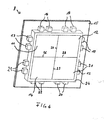
- FIG. 5 shows a further display device 50 which can be used instead of the display device 8 for the head-up display 5 shown in FIGS. 2 to 4.
- components of the display device 50 shown in FIG. 5, which are substantially identical in construction and function to components of the display device 8 shown in FIGS. 2 to 4, are given the same reference numerals.
- the display device 50 shown in FIG. 5 differs substantially from the display device 8 shown in FIGS. 2 to 5 by its backlight.
- This comprises, in addition to the four partial light guides 11-14, a fifth partial light conductor 51, which is embedded in the first partial light conductor 11 and in the case of the present embodiment has the shape of a vehicle with an open tailgate.
- the interface between the fifth partial light conductor 51 and the first partial light conductor 11 is provided with an opaque layer 52 which decouples the fifth partial light conductor 51 and the first partial light conductor 11.
- the opaque layer 52 was applied to the fifth partial light guide 51 by means of color printing.
- the display device 50 In addition to the light-emitting diodes 16-23 connected to the control device 25, which are arranged on printed circuit boards 53, the display device 50 also has a yellow light-emitting diode 54 and a red light-emitting diode 55.
- the two light-emitting diodes 54, 55 are provided with their light in the fifth partial light guide 51 and are also connected to the control device 25.
- the control device 25 is set up in such a way that it receives the yellow light-emitting diode 54 of the fifth partial light conductor 51 controls when the tailgate 30 of the passenger car PKW is locked. As a result, the fifth partial light conductor 51 backlit the liquid crystal panel 9 yellow.
- the control device 25 controls the red light-emitting diode 55 so that the fifth partial light conductor 51 backlit the liquid crystal screen 9 in red.
- the control device 25 controls the red light-emitting diode 55 so that the fifth partial light conductor 51 backlit the liquid crystal screen 9 in red.
- a red illuminated projected image of a vehicle with open tailgate on yellow background appears when the first part of the light guide 11 backlit the yellow liquid crystal screen. Due to the opaque layer 52 of the fifth part of the light guide 51 interfere with the coupled colors of the first and fifth partial light guide 11, 51 if, then only slightly, whereby the projected image of the vehicle with open tailgate is relatively sharp.
- the present invention has been described in terms of preferred embodiments, the invention is not limited to these, but modifiable in many ways.
- the selected colors of the yellow and red LEDs are to be understood as exemplary only.
- the two light guides 5 and 6 may be decoupled from each other by other methods, for example by a light-reflecting layer or a thin film.
- the two optical fibers are rectangular.
- it is possible that at least one of the two optical fibers has the shape of a symbol, so that a symbol with a color which differs from the color of the remaining backlight appears on the liquid crystal screen. It can also be used more than two light guides.
Abstract
Description
Die Erfindung betrifft ein Head-up Display, ein Kraftfahrzeug und ein Verfahren zum Betreiben eines Head-up Displays.The invention relates to a head-up display, a motor vehicle and a method for operating a head-up display.
Ein sogenanntes Head-up Display (HUD) ist ein Anzeigesystem, bei dem für einen Nutzer, z.B. einen Autofahrer oder einen Pilot eines Flugzeugs, Informationen in sein Sichtfeld projiziert werden. Für Piloten existieren solche Systeme bereits seit den 40er Jahren des 20. Jahrhunderts und wurden seinerzeit als Reflexvisiere bezeichnet.A so-called head-up display (HUD) is a display system in which for a user, e.g. a motorist or a pilot of an aircraft, information is projected into his field of vision. For pilots such systems already exist since the 40s of the 20th century and were referred to at that time as Reflexvisiere.
Ein Head-up Display umfasst im Allgemeinen eine Anzeigevorrichtung und eine Optikvorrichtung, die mit einem sogenannten Combiner zusammen wirken. Die Anzeigevorrichtung erzeugt ein Bild, woraus die Optikvorrichtung, z.B. umfassend eine Linse und einen Hohlspiegel, ein virtuelles Bild erzeugt, das der Fahrer oder Pilot in einer spiegelnden, lichtdurchlässigen Scheibe, dem Combiner, sieht. Der Combiner überlagert somit das virtuelle Bild mit den durch den Combiner hindurchscheinenden Informationen der Umwelt.A head-up display generally includes a display device and an optical device that interact with a so-called combiner. The display device generates an image from which the optical device, eg comprising a lens and a concave mirror, generates a virtual image that the driver or pilot sees in a specular translucent disk, the combiner. The combiner thus superimposes the virtual image with the environmental information transmitted through the combiner.
Wird ein Head-up Display in ein Kraftfahrzeug eingebaut, so wird in der Regel die Windschutzscheibe des Kraftfahrzeugs als Combiner verwendet.If a head-up display is installed in a motor vehicle, the windshield of the motor vehicle is usually used as a combiner.
Für eine relativ gute Ablesbarkeit des virtuellen Bildes sollte die Anzeigevorrichtung nicht nur ein ausreichend helles, sondern möglichst auch ein farbiges Bild erzeugen.For a relatively good readability of the virtual image, the display device should not only produce a sufficiently bright, but possibly also a colored image.
Die
Der
Die Aufgabe der vorliegenden Erfindung ist es, ein in der Fertigung relativ kostengünstiges Head-up Display bereit zu stellen, dessen Bild verschieden farbig ist.The object of the present invention is to provide a relatively inexpensive head-up display in production whose image is colored differently.
Die Aufgabe der Erfindung wird gelöst durch ein Head-up Display mit einer monochromen Anzeigevorrichtung zum Erzeugen eines Bildes und einer Optikvorrichtung zum Erzeugen eines virtuellen Bildes aus dem Bild der Anzeigevorrichtung, wobei die monochrome Anzeigevorrichtung eine Anzeige und eine für ein Hinterleuchten der Anzeige vorgesehene Hintergrundbeleuchtung aufweist und die Hintergrundbeleuchtung eine Licht mit einer ersten Farbe abgebende erste Lichtquelle, eine Licht mit einer zweiten Farbe abgebende zweite Lichtquelle, einen mit der ersten Lichtquelle gekoppelten ersten Lichtleiter und einen mit der zweiten Lichtquelle gekoppelten zweiten Lichtleiter aufweist, wobei die beiden Lichtleiter derart dicht nebeneinander hinter der Anzeige der Anzeigenvorrichtung angeordnet sind, dass sie die gesamte Anzeige flächenhaft und einen dem ersten Lichtleiter zugeordneten Bereich der Anzeige mit der ersten Farbe und einen den zweiten Lichtleiter zugeordneten Bereich der Anzeige mit der zweiten Farbe hinterleuchten. Dadurch ist es möglich, die beiden Bereiche mit voneinander verschiedenen Farben zu hinterleuchten und gleichzeitig die gesamte Anzeige flächenhaft zu hinterleuchten, ohne dass sich die Beleuchtungen der beiden Bereiche wenn, dann nur kaum gegenseitig beeinflussen. Somit sind Vorraussetzungen geschaffen, ein verschieden farbiges Bild mit der relativ kostengünstig herstellbaren monochromen Anzeigevorrichtung zu erzeugen, was wiederum eine Vorraussetzung zum Erzeugen eines verschieden farbigen virtuellen Bildes ist. Unter einem Bild bzw. einem projizierten Bild wird jegliche Art angezeigter Information, also auch Zahlen, Buchstaben oder Symbole, verstanden.The object of the invention is achieved by a head-up display with a monochrome display device for generating an image and an optical device for generating a virtual image from the image of the display device, wherein the monochrome display device has a display and provided for backlighting the display backlight and the backlight a light having a first color emitting first light source, a light having a second color Color emitting second light source having a first light source coupled to the first optical fiber and a second light source coupled to the second optical fiber, wherein the two optical fibers are arranged so close to each other behind the display of the display device, that the entire display areal and one of the first light guide associated region of the display with the first color and the second light guide associated region of the display with the second color behind. This makes it possible to backlight the two areas with different colors and at the same time backlit the entire display without the lighting of the two areas if, then hardly influence each other. Thus, prerequisites are created to produce a differently colored image with the relatively inexpensive monochrome display device, which in turn is a prerequisite for generating a differently colored virtual image. An image or a projected image is understood to be any type of displayed information, including numbers, letters or symbols.
Die Gefahr einer Beeinflussung der beiden Bereiche lässt sich gemäß einer bevorzugten Variante des erfindungsgemäßen Head-up Displays verringern, wenn die beiden Lichtleiter durch eine lichtundurchlässige und/oder lichtreflektierende Schicht voneinander getrennt sind. Die Schicht ist beispielsweise eine dünne Folie oder kann bevorzugt mittels Farbdruck aufgebracht werden.The risk of influencing the two areas can be reduced according to a preferred variant of the head-up display according to the invention if the two light guides are separated from one another by an opaque and / or light-reflecting layer. The layer is for example a thin film or may preferably be applied by means of color printing.
Die beiden Farben können verschieden, identisch und/oder einstellbar sein.The two colors can be different, identical and / or adjustable.
Wenn nach einer Ausführungsform des erfindungsgemäßen Head-up Displays als Anzeige ein Flüssigkristallbildschirm verwendet wird, dann kann das Head-up Display besonders preisgünstig hergestellt werden.When according to an embodiment of the head-up display according to the invention as a display, a liquid crystal screen is used, then the head-up display can be made particularly inexpensive.
Besonders attraktiv kann das erfindungsgemäße Head-up Display ausgeführt werden, wenn nach einer Variante wenigstens einer der Teillichtleiter die Form eines Symbols hat. Ein solches Symbol ist z.B. ein Markenzeichen.The head-up display according to the invention can be embodied particularly attractively if, according to a variant, at least one of the partial light guides has the form of a symbol. Such a symbol is e.g. a trademark.
Das erfindungsgemäße Head-up Display wird insbesondere bei einem Kraftfahrzeug, z.B. als Kombiinstrument zum Anzeigen von verschiedenen Fahrzeugparametern, verwendet. Bei der Verwendung in dem Kraftfahrzeug kann das erfindungsgemäße Head-up Display insbesondere zum Durchführen eines Verfahrens mit folgenden Verfahrensschritten verwendet werden:
- Einkoppeln von Licht der ersten Farbe in den ersten Lichtleiter und in den zweiten Lichtleiter, die derart nebeneinander hinter der Anzeige der Anzeigenvorrichtung angeordnet sind, sodass sie im Wesentlichen die gesamte Anzeige flächenhaft mit der ersten Farbe hinterleuchten, und
- Wechseln der Farbe des eingekoppelten Lichts in den zweiten Lichtleiter von der ersten Farbe auf eine von der ersten Farbe verschiedenen zweiten Farbe aufgrund eines von einer Steuereinrichtung des Fahrzeugs abgegebenen Signals, sodass ein dem ersten Lichtleiter zugeordneter Bereich der Anzeige mit der ersten Farbe und ein dem zweiten Lichtleiter zugeordneter Bereich der Anzeige mit der zweiten Farbe hinterleuchtet wird.
- Coupling light of the first color into the first light guide and into the second light guide, which are arranged side by side behind the display of the display device such that they illuminate substantially the entire display areally with the first color, and
- Changing the color of the injected light into the second optical fiber from the first color to a second color different from the first color due to a signal outputted from a controller of the vehicle, such that a portion of the first color display and the second color associated with the first optical fiber are changed Light guide assigned area of the display with the second color is backlit.
Durch dieses Verfahren ist es möglich, im Wesentlichen die gesamte Anzeige zunächst mit der ersten Farbe zu hinterleuchten. Gibt die Steuereinrichtung das Signal ab, so wechselt die zweite Farbe ihre Farbe, d.h. die Anzeige wird im Bereich des zweiten Lichtleiters mit der zweiten Farbe hinterleuchtet. Aufgrund der beiden Lichtleiter, die bevorzugt durch eine lichtundurchlässige und/oder lichtreflektierende voneinander entkoppelt sind, stört jedoch die zweite Farbe den vom ersten Lichtleiter hinterleuchteten Bereich der Anzeige nicht oder nur kaum. Der von dem zweiten Lichtleiter hinterleuchtete Bereich der Anzeige ist beispielsweise einem Warnsignal zugeordnet, sodass die Steuereinrichtung das Signal abgibt, wenn ein Fahrzeuglenker bzw. eine Fahrzeuglenkerin des Kraftfahrzeugs gewarnt werden soll. Der von dem zweiten Lichtleiter hinterleuchtete Bereich der Anzeige wird daraufhin mit der zweiten Farbe, z.B. Rot, hinterleuchtet.By this method, it is possible to backlight substantially the entire display first with the first color. If the control device emits the signal, the second color changes its color, ie the display is backlit in the area of the second light guide with the second color. Due to the two light guides, which are preferably decoupled from one another by an opaque and / or light-reflecting, however, the second color does not interfere with the region of the display backlit by the first light guide, or only slightly. The area of the display illuminated by the second optical waveguide is associated, for example, with a warning signal, so that the control device emits the signal when a vehicle driver or driver of the motor vehicle is to be warned. The illuminated by the second light guide portion of the display is then backlit with the second color, eg red.
Mit dem erfindungsgemäßen Head-up Display wird somit u.a. ein Head-up Display mit einer hinterleuchteten Anzeigevorrichtung bereitgestellt, dessen Licht in die beiden Lichtleiter eingekoppelt wird und von diesen hinter der Anzeige, z.B. dem Glas eines Flüssigkristallbildschirms, abgegeben wird. Die Anzeige umfasst mehrere Beleuchtungszonen, die jeweils von einem der beiden Lichtleiter hinterleuchtet werden. Die Lichtleiter sind direkt nebeneinander gefügt. Um die Gefahr eines Lichtübertritts von einem Lichtleiter zum anderen Lichtleiter zu vermeiden, wird bevorzugt an der Trennfläche der beiden Lichtleiter die dünne lichtundurchlässige oder lichtreflektierende Schicht eingefügt. Dies erlaubt insbesondere folgende Nutzung:With the head-up display according to the invention is thus u.a. a head-up display provided with a backlit display device whose light is coupled into the two light guides and from behind the display, e.g. the glass of a liquid crystal display. The display includes several lighting zones, each of which is backlit by one of the two light guides. The light guides are joined directly next to each other. In order to avoid the risk of light passing from one light guide to the other light guide, the thin opaque or light-reflecting layer is preferably inserted at the interface of the two light guides. This allows in particular the following use:
Die gesamte Anzeige der Anzeigevorrichtung kann komplett mit seiner üblichen Hinterleuchtungsfarbe genutzt werden. Dazu wird in den beiden Lichtleitern zunächst Licht mit derselben Farbe eingekoppelt. Die gesamte Anzeige wird dann im Wesentlichen mit dieser Farbe hinterleuchtet. Wenn eine Warnanzeige z.B. in der Farbe Rot dargestellt werden soll, wird das zugehörige Symbol in dem Bereich des zweiten Lichtleiters erzeugt. Nur in diesem Bereich wird dann die rote anstelle der gelben Hinterleuchtung aktiviert, indem in den zweiten Lichtleiter ein rotes Licht eingekoppelt wird.The entire display of the display device can be used completely with its usual backlight color. For this purpose, light in the two light guides is first coupled with the same color. The entire display is then backlit essentially with this color. If, for example, a warning display is to be displayed in the color red, the associated symbol becomes generated in the region of the second light guide. Only in this area is then the red instead of the yellow backlight activated by a red light is coupled into the second light guide.
Da die Trennfläche zwischen den beiden Lichtleitern relativ dünn ausgeführt werden kann, wird die gesamte Anzeige der Anzeigevorrichtung im Wesentlichen über die gesamte Fläche gleichmäßig hinterleuchtet, wenn in beiden Lichtleitern ein Licht derselben Farbe eingekoppelt wird.Since the interface between the two light guides can be made relatively thin, the entire display of the display device is uniformly backlit substantially over the entire surface when a light of the same color is coupled in both light guides.
Die Aufgabe wird auch gelöst durch ein Head-up Display mit einer Anzeigevorrichtung zum Erzeugen eines Bildes und einer Optikvorrichtung zum Erzeugen eines virtuellen Bildes aus dem Bild der Anzeigevorrichtung, wobei die Anzeigevorrichtung einen ersten Lichtleiter, einen zweiten Lichtleiter, eine erste Lichtquelle, die Licht mit einer ersten Farbe in den ersten Lichtleiter einkoppelt, und eine zweite Lichtquelle, die Licht mit einer zweiten Farbe in den zweiten Lichtleiter einkoppelt, aufweist, wobei die beiden Lichtleiter derart dicht nebeneinander angeordnet sind, dass sie im Wesentlichen eine als Anzeigefläche ausgebildete Fläche bilden, und durch eine lichtundurchlässige und/oder lichtreflektierende Schicht voneinander getrennt sind. Durch die lichtabsorbierende bzw. lichtreflektierende Schicht, die bevorzugt eine dünne Folie ist oder mittels Farbdruck aufgebracht wird, wird einerseits ein Überlappen von zwei verschiedenfarbigen, in die beiden Lichtleiter eingekoppelte Lichter verhindert und andererseits ergibt sich eine optisch durchgehende Anzeigeoberfläche, die durch keine nichtbeleuchteten Begrenzungen durchbrochen wird.The object is also achieved by a head-up display having a display device for generating an image and an optical device for generating a virtual image from the image of the display device, the display device having a first light guide, a second light guide, a first light source, the light coupling a first color into the first light guide, and a second light source coupling light with a second color into the second light guide, wherein the two light guides are arranged close to each other so that they form a substantially formed as a display surface area, and are separated by an opaque and / or light-reflecting layer. The light-absorbing or light-reflecting layer, which is preferably a thin film or is applied by means of color printing, on the one hand prevents overlapping of two differently colored lights coupled into the two light guides and, on the other hand, results in an optically continuous display surface which is not interrupted by any non-illuminated boundaries becomes.
Vorteile der erfindungsgemäßen Head-up Displays sind u.a.:Advantages of the head-up displays according to the invention include:
Es ergeben sich Kostenvorteile aufgrund der Verwendung einer monochromen Anzeigevorrichtung für ein Head-up Display zur Visualisierung von Farbinformationen. Im Vergleich zu gewöhnlichen farbigen Anzeigevorrichtungen kann die Hintergrundbeleuchtung für die erfindungsgemäßen Head-up Displays weniger stark leuchtend ausgeführt werden, da eine monochrome Anzeige eine relativ große Transmission aufweist. Dies wirkt sich positiv auf den Preis der verwendeten Lichtquelle aus.There are cost advantages due to the use of a monochrome display device for a head-up display for visualizing color information. Compared to ordinary color display devices, the backlight for the head-up displays according to the invention can be made less bright because a monochrome display has a relatively large transmission. This has a positive effect on the price of the light source used.
Aufgrund der höheren Transmission der monochromen Anzeige sind Vorraussetzungen für ein relativ helles Bild und daher für ein relativ helles virtuelles Bild gegeben. Aufgrund der erfindungsgemäßen Lichtleiterstruktur ergibt sich trotz Verwendung der monochromen Anzeige ein verschieden farbiges Bild.Due to the higher transmission of the monochrome display, there are prerequisites for a relatively bright image and therefore for a relatively bright virtual image. Due to the optical waveguide structure according to the invention results in a differently colored image despite the use of the monochrome display.
Bestimmte Symbole, wie z.B. ein Warnsymbol, Kreise oder Kurven, können fest in der Lichtleiterstruktur hinterlegt werden. Dadurch kann eine monochrome Anzeige mit einer relativ geringen Auflösung verwendet werden, wodurch wiederum Kosten gespart werden können.Certain symbols, such as a warning symbol, circles or curves, can be stored firmly in the light guide structure. This allows a monochrome display with a relatively low resolution can be used, which in turn costs can be saved.
Es ergibt sich eine relativ einfache Skalierung des Farbumfangs der erfindungsgemäßen Head-up Displays.This results in a relatively simple scaling of the color gamut of the head-up displays according to the invention.
Ausführungsbeispiele der Erfindung sind in den beigefügten schematischen Zeichnungen exemplarisch dargestellt. Es zeigen:
- Figur 1
- Einen Personenkraftwagen,
Figur 2- einen Teil des Personenkraftwagens der Fig. 1 mit einem Headup Display,
Figuren 3, 4- die Anzeigevorrichtung des Head-up Displays der Fig. 2 und
- Figur 5
- eine weitere Anzeigevorrichtung für das Head-up Display der Fig. 2.
- FIG. 1
- A passenger car,
- FIG. 2
- a part of the passenger car of FIG. 1 with a headup display,
- FIGS. 3, 4
- the display device of the head-up display of Fig. 2 and
- FIG. 5
- a further display device for the head-up display of FIG. 2.
Die Fig. 1 zeigt einen Personenkraftwagen PKW mit einer Windschutzscheibe 2 und einem Armaturenbrett 3, an dem ein Lenkrad 4 angeordnet und in dem im Falle des vorliegenden Ausführungsbeispiels ein in den Figuren 2 bis 4 näher dargestelltes Head-up Display 5 befestigt ist. Das Head-up Display 5 ist dafür vorgesehen, in einem Projektionsbereich 6 der Windschutzscheibe 2 ein Bild zu projizieren.Fig. 1 shows a passenger car PKW with a
Das Head-up Display 5 umfasst eine Optikvorrichtung 7 und eine in den Figuren 3 und 4 näher dargestellte Anzeigevorrichtung 8 zum Erzeugen eines Bildes. Das von der Anzeigevorrichtung 8 erzeugte Bild wird in die Optikvorrichtung 7 eingekoppelt, die daraufhin in Allgemein bekannter Weise, wie es z.B. aus der
Der Projektionsbereich 6 befindet sich im Sichtbereich eines nicht näher dargestellten Fahrzeuglenkers bzw. einer nicht näher dargestellten Fahrzeuglenkerin des Personenkraftwagens PKW, sodass der Projektionsbereich 6 das virtuelle Bild mit den durch die Windschutzscheibe 2 hindurchscheinenden Informationen der Umwelt überlagert. Im Falle des vorliegenden Ausführungsbeispiels ist das Head-up Display 5 dafür vorgesehen, den Fahrzeuglenker bzw. die Fahrzeuglenkerin über Fahrzeugparameter des Personenkraftwagens PKW zu informieren.The projection area 6 is located in the field of vision of a vehicle driver not shown in more detail or a vehicle driver of the passenger car, not shown, so that the projection area 6 superimposes the virtual image with the information that shines through the
Die Anzeigevorrichtung 8 umfasst im Falle des vorliegenden Ausführungsbeispiels einen Flüssigkristallbildschirm 9 als Anzeige und eine direkt auf der Rückseite des Flüssigkristallbildschirms 9 angeordnete Hintergrundbeleuchtung zum Hinterleuchten des Flüssigkristallbildschirmes 9. Die Hintergrundbeleuchtung weist im Falle des vorliegenden Ausführungsbeispieles einen Lichtleiter 10 aus Plexiglas auf. Der Lichtleiter 10 weist im Falle des vorliegenden Ausführungsbeispiels vier Teillichtleiter 11-14 auf, die sich gemeinsam im Wesentlichen über die gesamte Fläche der Rückseite des Flüssigkristallbildschirmes 9 erstrecken.In the case of the present embodiment, the
Der Leichtleiter 10 ist auf einer Leiterplatte 15 mit Leuchtdioden 16-23 angeordnet, die jeweils seitlich Licht in den Lichtleiter 10 einkoppeln. Im Falle des vorliegenden Ausführungsbeispiels sind jedem der vier Teillichtleiter 11-14 jeweils vier Leuchtdioden zugeordnet, die verschiedenfarbiges Licht emittieren. Seitlich am ersten Teillichtleiter 13 sind im Falle des vorliegenden Ausführungsbeispiels gelbes Licht emittierende gelbe Leuchtdioden 16 und rotes Licht emittierende Leuchtdioden 17 angeordnet. Seitlich am zweiten Teillichtleiter 12 sind gelbes Licht emittierende gelbe Leuchtdioden 18 und grünes Licht emittierende Leuchtdioden 19 angeordnet. Seitlich am dritten Teillichtleiter 13 sind gelbes Licht emittierende gelbe Leuchtdioden 20 und rotes Licht emittierende Leuchtdioden 21 angeordnet. Seitlich am vierten Teillichtleiter 14 sind gelbes Licht emittierende gelbe Leuchtdioden 22 und grünes Licht emittierende Leuchtdioden 23 angeordnet.The
Des Weitern umfasst die Hintergrundbeleuchtung einen Reflektor 24, der seitlich den Lichtleiter 10 einrahmt. Außerdem sind die vier Teillichtleiter 11-14 an denjenigen Grenzflächen, mit denen sich die Teillichtleiter 11-14 jeweils berühren, mit jeweils einer dünnen lichtundurchlässigen Schicht 26-29, die im Falle des vorliegenden Ausführungsbeispieles mittels Farbdruck auf den ersten Teillichtleiter 11 und den dritten Teillichtleiter 13 aufgebracht wurden, entkoppelt.The Weitern includes the backlight a
Die Leuchtdioden 16-23 sind in nicht dargestellter Weise mit einer unterhalb des Armaturenbrettes 3 des Personenkraftwagens PKW angeordneten Steuerungsvorrichtung 25 elektrisch verbunden, die die Leuchtdioden 16-23 einzeln ansteuert. Im Falle des vorliegenden Ausführungsbeispiels kann mittels der Steuerungsvorrichtung 25 die Intensität des emittierenden Lichts der Leuchtdioden 16-23 eingestellt bzw. können die Leuchtdioden 16-23 ein- und ausgeschaltet werden.The light-emitting diodes 16-23 are electrically connected in a manner not shown with a arranged below the
Im Falle des vorliegenden Ausführungsbeispiels kann die Hintergrundbeleuchtung in verschiedenen Betriebszuständen betrieben werden. In einem ersten Betriebeszustand ist es vorgesehen, dass nur die gelben Leuchtdioden 16, 18, 20, 22 von der Steuerungsvorrichtung 25 angesteuert werden und die restlichen Leuchtdioden ausgeschaltet sind. In diesem Betriebszustand wird der gesamte Flüssigkristallbildschirm 9 gelb hinterleuchtet.In the case of the present embodiment, the backlight can be operated in various operating states. In a first operating state, it is provided that only the
In einem zweiten Betriebszustand kann der Fahrzeuglenker bzw. die Fahrzeuglenkerin auch die Hintergrundfarben der den einzelnen Teillichtleitern 11-14 zugeordneten Anzeigeteilflächen des Flüssigkristallbildschirms 9 einstellen. So ist es im Falle des vorliegenden Ausführungsbeispiels vorgesehen, dass die gelben Leuchtdioden 16 des ersten Teillichtleiters 11 ausgeschaltet und dafür die roten Leuchtdioden 17 des ersten Teillichtleiters 11 eingeschaltet sind. Auch ist es möglich, anstelle der gelben Leuchtdioden 18 die grünen Leuchtdioden 19 des zweiten Teillichtleiters 12 einzuschalten, wodurch derjenige Teil des Flüssigkristallbildschirms 9 grün hinterleuchtet wird, der dem zweiten Teillichtleiter 12 zugeordnet ist. Sinngemäß dasselbe gilt für den dritten Teillichtleiter 13 und den vierten Teillichtleiter 14.In a second operating state, the vehicle driver can also adjust the background colors of the display partial areas of the liquid crystal display screen 9 assigned to the individual partial light guides 11-14. Thus, in the case of the present exemplary embodiment, it is provided that the yellow light-emitting
Aufgrund der mit den dünnen lichtundurchlässigen Schichten 26-29 beschichteten Grenzflächen, mit denen sich die Teillichtleiter 11-14 jeweils berühren, wird verhindert, dass in einen der Teillichtleiter eingekoppeltes Licht auch in einen der anderen Teillichtleiter eingekoppelt wird.Due to the coated with the thin opaque layers 26-29 interfaces, with which the partial light conductors 11-14 each touch, prevents that coupled into one of the partial light guide light is coupled into one of the other part of the light guide.
Im Falle des vorliegenden Ausführungsbeispiels kann das Head-up Display 5 in einem dritten Betriebszustand betrieben werden. Im dritten Betriebszustand sind nur die gelben Leuchtdioden 16, 18, 20, 22 eingeschaltet und die restlichen Leuchtdioden ausgeschaltet. Soll der Fahrzeuglenker bzw. die Fahrzeuglenkerin z.B. auf den dem ersten Teillichtleiter 11 zugeordneten hinterleuchteten Bildinhalt aufmerksam gemacht werden, so schaltet die Steuerungsvorrichtung 25 automatisch die gelben Leuchtdioden 16 des ersten Teillichtleiter 11 aus und die roten Leuchtdioden 17 des ersten Teillichtleiter 11 ein.In the case of the present embodiment, the head-up display 5 can be operated in a third operating state. In the third operating state, only the
Aufgrund der mit den dünnen lichtundurchlässigen Schichten 26-29 beschichteten Grenzflächen, mit denen sich die Teillichtleiter 11-14 jeweils berühren, stört das rote Licht das in den ersten Teillichtleiter 11 eingekoppelt wird, die den restlichen Teillichtleitern 12-14 zugeordneten Teilanzeigeflächen, die den Flüssigkristallbildschirm 9 gelb hinterleuchten, nicht.Due to the coated with the thin opaque layers 26-29 interfaces, with which the partial light conductors 11-14 respectively touch, the red light is coupled into the first part of the
Die Figur 5 zeigt eine weitere Anzeigevorrichtung 50, die anstelle der in den Figuren 2 bis 4 gezeigten Anzeigevorrichtung 8 für das Head-up Display 5 verwendet werden kann. Wenn folgend nicht anders beschrieben, dann sind Bestandteile der in der Figur 5 gezeigten Anzeigevorrichtung 50, die mit Bestandteilen der in den Figuren 2 bis 4 gezeigten Anzeigevorrichtung 8 weitgehend bau- und funktionsgleich sind, mit denselben Bezugszeichen versehen.FIG. 5 shows a further display device 50 which can be used instead of the
Die in der Figur 5 dargestellte Anzeigevorrichtung 50 unterscheidet sich im Wesentlichen von der in den Figuren 2 bis 5 gezeigten Anzeigevorrichtung 8 durch ihre Hintergrundbeleuchtung. Diese umfasst zusätzlich zu den vier Teillichtleitern 11-14 einen fünften Teillichtleiter 51, der in dem ersten Teillichtleiter 11 eingelassen ist und im Falle des vorliegenden Ausführungsbeispiels die Form eines Fahrzeugs mit offener Heckklappe hat. Die Grenzfläche zwischen dem fünften Teillichtleiter 51 und dem ersten Teillichtleiter 11 ist im Falle des vorliegenden Ausführungsbeispiels mit ein lichtundurchlässigen Schicht 52 versehen, die den fünften Teillichtleiter 51 und den ersten Teillichtleiter 11 entkoppeln. Die lichtundurchlässige Schicht 52 wurde mittels Farbdruck auf den fünften Teillichtleiter 51 aufgebracht.The display device 50 shown in FIG. 5 differs substantially from the
Die Anzeigevorrichtung 50 umfasst neben den mit der Steuerungsvorrichtung 25 verbundenen Leuchtdioden 16-23, die auf Leiterplatten 53 angeordnet sind, noch eine gelbe Leuchtdiode 54 und eine rote Leuchtdiode 55. Die beiden Leuchtdioden 54, 55 sind dafür vorgesehen, ihr Licht in den fünften Teillichtleiter 51 einzukoppeln, und sind ebenfalls mit der Steuerungsvorrichtung 25 verbunden. Die Steuerungsvorrichtung 25 ist im Fall des vorliegenden Ausführungsbeispiel derart eingerichtet, dass sie die gelbe Leuchtdiode 54 des fünften Teillichtleiters 51 ansteuert, wenn die Heckklappe 30 des Personenkraftwagens PKW verriegelt ist. Dadurch hinterleuchtet der fünfte Teillichtleiter 51 den Flüssigkristallbildschirm 9 gelb. Ist die Heckklappe 30 des Personenkraftwagens PKW dagegen nicht verriegelt, dann steuert die Steuerungsvorrichtung 25 die rote Leuchtdiode 55 an, sodass der fünfte Teillichtleiter 51 den Flüssigkristallbildschirm 9 rot hinterleuchtet. Dadurch erscheint im Projektionsbereich 6 der Windschutzscheibe 2 ein rot erleuchtetes projiziertes Bild eines Fahrzeugs mit geöffneter Heckklappe auf gelben Hintergrund, wenn der erste Teillichtleiter 11 den Flüssigkristallbildschirm gelb hinterleuchtet. Aufgrund der lichtundurchlässigen Schicht 52 des fünften Teillichtleiters 51 stören sich die eingekoppelten Farben des ersten und fünften Teillichtleiters 11, 51 wenn, dann nur unwesentlich, wodurch das projizierte Bild des Fahrzeugs mit offener Heckklappe relativ scharf ist.In addition to the light-emitting diodes 16-23 connected to the
Obwohl die vorliegende Erfindung anhand bevorzugter Ausführungsbeispiele beschrieben wurde, ist die Erfindung nicht auf diese beschränkt, sondern auf vielfältige Weise modifizierbar. Insbesondere sind die gewählten Farben der gelben und der roten Leuchtdioden nur exemplarisch zu verstehen. Außerdem können die beiden Lichtleiter 5 und 6 auch durch andere Methoden voneinander entkoppelt sein, beispielsweise durch eine lichtreflektierende Schicht oder eine dünnen Folie. Auch ist es nicht notwendig, dass die beiden Lichtleiter recheckförmig sind. Insbesondere ist es möglich, dass wenigstens einer der beiden Lichtleiter die Form eine Symbols hat, sodass auf dem Flüssigkristallbildschirm ein Symbol mit einer Farbe, die sich von der Farbe restlichen Hintergrundbeleuchtung unterscheidet, erscheint. Es können auch mehr als zwei Lichtleiter verwendet werden.Although the present invention has been described in terms of preferred embodiments, the invention is not limited to these, but modifiable in many ways. In particular, the selected colors of the yellow and red LEDs are to be understood as exemplary only. In addition, the two light guides 5 and 6 may be decoupled from each other by other methods, for example by a light-reflecting layer or a thin film. Also, it is not necessary that the two optical fibers are rectangular. In particular, it is possible that at least one of the two optical fibers has the shape of a symbol, so that a symbol with a color which differs from the color of the remaining backlight appears on the liquid crystal screen. It can also be used more than two light guides.
- 22
- WindschutzscheibeWindshield
- 33
- Armaturenbrettdashboard
- 44
- Lenkradsteering wheel
- 55
- Head-up DisplayHead-Up Display
- 66
- Projektionsbereichprojection area
- 77
- Optikvorrichtungoptical device
- 88th
- Anzeigevorrichtungdisplay device
- 99
- Flüssigkristallbildschirmliquid crystal display
- 1010
- Lichtleiteroptical fiber
- 11-1411-14
- TeillichtleiterPart light guide
- 1515
- Leiterplattecircuit board
- 16-2316-23
- LeuchtdiodenLEDs
- 2424
- Reflektorreflector
- 2525
- Steuerungsvorrichtungcontrol device
- 26-2926-29
- lichtdurchlässige Schichttranslucent layer
- 3030
- Heckklappetailgate
- 5050
- Anzeigevorrichtungdisplay device
- 5151
- TeillichtleiterPart light guide
- 5252
- Lichtundurchlässige SchichtOpaque layer
- 5353
- LeiterplattenPCBs
- 5454
- gelbe Leuchtdiodeyellow LED
- 5555
- rote Leuchtdiodered LED
- PKWcar
- PersonenkraftwagenPassenger cars
Claims (16)
Applications Claiming Priority (1)
| Application Number | Priority Date | Filing Date | Title |
|---|---|---|---|
| DE102006014394A DE102006014394A1 (en) | 2006-03-29 | 2006-03-29 | Head-up display, motor vehicle and method for operating a head-up display |
Publications (2)
| Publication Number | Publication Date |
|---|---|
| EP1840626A1 true EP1840626A1 (en) | 2007-10-03 |
| EP1840626B1 EP1840626B1 (en) | 2016-05-11 |
Family
ID=38181108
Family Applications (1)
| Application Number | Title | Priority Date | Filing Date |
|---|---|---|---|
| EP07006337.5A Not-in-force EP1840626B1 (en) | 2006-03-29 | 2007-03-28 | Head-up display, motor vehicle und method for operating a head-up display |
Country Status (3)
| Country | Link |
|---|---|
| US (1) | US7762703B2 (en) |
| EP (1) | EP1840626B1 (en) |
| DE (1) | DE102006014394A1 (en) |
Cited By (4)
| Publication number | Priority date | Publication date | Assignee | Title |
|---|---|---|---|---|
| EP2063297A1 (en) * | 2007-11-22 | 2009-05-27 | Panasonic Corporation | Light guide sheet, movable contact structure using the light guide sheet, method of manufacturing the movable contact structure, and switch using the light guide sheet and the movable contact structure |
| WO2010102777A1 (en) * | 2009-03-10 | 2010-09-16 | Gm Global Technology Operations, Inc. | Display device for a vehicle and method for producing the display device |
| CN101440936B (en) * | 2007-11-22 | 2013-07-17 | 松下电器产业株式会社 | Light guide sheet, movable contact structure using the light guide sheet, method of manufacturing the movable contact structure, and switch using the light guide sheet and the movable contact structur |
| IT201800002897A1 (en) * | 2018-02-21 | 2019-08-21 | Automotive Lighting Italia Spa | AUTOMOTIVE LIGHTING AND / OR SIGNALING DEVICE WITH SEGMENTED ILLUMINATING PORTIONS |
Families Citing this family (13)
| Publication number | Priority date | Publication date | Assignee | Title |
|---|---|---|---|---|
| TW200921208A (en) * | 2007-11-07 | 2009-05-16 | Nano Prec Corp | Side-emitting backlight module |
| DE102009011908B4 (en) | 2009-03-05 | 2021-12-09 | Bayerische Motoren Werke Aktiengesellschaft | Head-up display and vehicle |
| EP2292972B1 (en) * | 2009-09-02 | 2013-03-27 | 3M Innovative Properties Company | Light device and vehicle including light device |
| FR2979081A1 (en) * | 2011-08-18 | 2013-02-22 | Johnson Contr Automotive Elect | DISPLAY DEVICE, IN PARTICULAR FOR A MOTOR VEHICLE |
| DE102011121558B4 (en) * | 2011-10-05 | 2017-06-01 | Johnson Controls Automotive Electronics Gmbh | Display device and method for operating a display device |
| US9302587B2 (en) * | 2014-04-25 | 2016-04-05 | Continental Automotive Systems, Inc. | Instrument cluster including telltale illumination using a light guide |
| US10429215B2 (en) * | 2014-09-30 | 2019-10-01 | Continental Automotive Systems, Inc. | LED beam display for interior automotive applications |
| KR102494031B1 (en) * | 2015-08-20 | 2023-02-01 | 삼성디스플레이 주식회사 | Liquid crystal display device and driving method of the same |
| KR101912648B1 (en) | 2017-06-02 | 2018-10-29 | 콘티넨탈 오토모티브 게엠베하 | Operating device foe head up display |
| DE102018202411A1 (en) * | 2018-02-16 | 2019-08-22 | Audi Ag | Display device and method for a motor vehicle for displaying at least one image symbol on a display element |
| JP2019209870A (en) * | 2018-06-06 | 2019-12-12 | スタンレー電気株式会社 | Decorative component for vehicle |
| JP2020121638A (en) * | 2019-01-30 | 2020-08-13 | アイシン精機株式会社 | Display control device |
| RU2732340C1 (en) * | 2019-05-17 | 2020-09-15 | Общество с ограниченной ответственностью "Научно-технический центр "Биолюмен" (ООО "НТЦ "Биолюмен") | Automotive display on windshield |
Citations (5)
| Publication number | Priority date | Publication date | Assignee | Title |
|---|---|---|---|---|
| EP0570037A1 (en) * | 1992-05-15 | 1993-11-18 | General Motors Corporation | Head-up display system |
| EP0707408A1 (en) * | 1994-10-11 | 1996-04-17 | International Business Machines Corporation | Optical scanner device for transparent media |
| EP1413470A1 (en) * | 2001-07-30 | 2004-04-28 | Nippon Seiki Co., Ltd. | Vehicle display device |
| WO2005045793A1 (en) * | 2003-11-06 | 2005-05-19 | Koninklijke Philips Electronics N.V. | Switchable transparent display |
| DE102004007802A1 (en) * | 2004-02-18 | 2005-09-08 | Robert Bosch Gmbh | Display device for motor vehicle has projection system consisting of individual, independent projection units arranged in row that is horizontal relative to bottom of vehicle and transverse to direction of travel |
Family Cites Families (20)
| Publication number | Priority date | Publication date | Assignee | Title |
|---|---|---|---|---|
| FR1588713A (en) | 1967-10-21 | 1970-04-17 | ||
| DE3301914A1 (en) | 1983-01-21 | 1984-07-26 | Licentia Patent-Verwaltungs-Gmbh, 6000 Frankfurt | Liquid crystal display device |
| GB8303619D0 (en) | 1983-02-09 | 1983-03-16 | Secr Defence | Colour head-up display system |
| DE3512099A1 (en) | 1985-03-29 | 1986-10-09 | Siemens Ag | Display device having pixels arranged row-wise and column-wise |
| DE3639008A1 (en) | 1986-11-14 | 1988-05-19 | Bosch Gmbh Robert | DISPLAY DEVICE WITH LIQUID CRYSTAL CELL, PREFERABLY FOR MOTOR VEHICLES |
| CA2023264C (en) | 1989-08-31 | 1995-03-21 | John J. Ferrer | Louvered reflective head-up display for automobiles |
| DE4203014A1 (en) | 1991-02-26 | 1992-08-27 | Siemens Ag | Light conductor, e.g. for illuminating vehicle computer display - contains luminescent material and has inclined surfaces to concentrate light onto display surface |
| JPH06130383A (en) * | 1992-10-21 | 1994-05-13 | Nippondenso Co Ltd | Display device |
| US5657163A (en) * | 1995-05-31 | 1997-08-12 | Delco Electronics Corporation | Fiber optic illumination of HUD image source |
| DE69624774T2 (en) * | 1995-12-05 | 2003-03-27 | Matsushita Electric Ind Co Ltd | Backlit color display |
| DE19816647C2 (en) | 1998-04-15 | 2000-12-14 | Daimler Chrysler Ag | Device for improving the contrast in a head-up display in a motor vehicle |
| DE10016817A1 (en) * | 2000-04-05 | 2001-10-18 | Mannesmann Vdo Ag | Color head-up display, especially for a vehicle |
| DE10021100A1 (en) | 2000-05-02 | 2001-11-15 | Bosch Gmbh Robert | Lighting device and method for lighting |
| JP4193367B2 (en) * | 2001-03-26 | 2008-12-10 | 株式会社デンソー | Vehicle display device |
| US6646810B2 (en) * | 2001-09-04 | 2003-11-11 | Delphi Technologies, Inc. | Display backlighting apparatus |
| US6962429B2 (en) * | 2002-07-19 | 2005-11-08 | Matsushita Electric Industrial Co., Ltd. | Backlight device and liquid crystal display |
| DE10344687A1 (en) | 2003-09-25 | 2005-05-12 | Siemens Ag | Head-up display with a light source illuminated TFT display for use in motor vehicles, aircraft or ships |
| DE20319732U1 (en) | 2003-12-19 | 2004-04-08 | Bauer, Manfred | Traffic and other signs incorporate a transparent front cover and an optional transparent rear cover which are provided with additional optical properties such as reflectivity and fluorescence |
| US7413328B2 (en) * | 2004-12-30 | 2008-08-19 | Honeywell International Inc. | Remotely coupled hybrid HUD backlight |
| DE102005045692A1 (en) * | 2005-09-24 | 2007-03-29 | GM Global Technology Operations, Inc., Detroit | A monochrome display device with a backlight, motor vehicle and method of operating a monochrome display device |
-
2006
- 2006-03-29 DE DE102006014394A patent/DE102006014394A1/en not_active Withdrawn
-
2007
- 2007-03-02 US US11/681,422 patent/US7762703B2/en not_active Expired - Fee Related
- 2007-03-28 EP EP07006337.5A patent/EP1840626B1/en not_active Not-in-force
Patent Citations (5)
| Publication number | Priority date | Publication date | Assignee | Title |
|---|---|---|---|---|
| EP0570037A1 (en) * | 1992-05-15 | 1993-11-18 | General Motors Corporation | Head-up display system |
| EP0707408A1 (en) * | 1994-10-11 | 1996-04-17 | International Business Machines Corporation | Optical scanner device for transparent media |
| EP1413470A1 (en) * | 2001-07-30 | 2004-04-28 | Nippon Seiki Co., Ltd. | Vehicle display device |
| WO2005045793A1 (en) * | 2003-11-06 | 2005-05-19 | Koninklijke Philips Electronics N.V. | Switchable transparent display |
| DE102004007802A1 (en) * | 2004-02-18 | 2005-09-08 | Robert Bosch Gmbh | Display device for motor vehicle has projection system consisting of individual, independent projection units arranged in row that is horizontal relative to bottom of vehicle and transverse to direction of travel |
Cited By (8)
| Publication number | Priority date | Publication date | Assignee | Title |
|---|---|---|---|---|
| EP2063297A1 (en) * | 2007-11-22 | 2009-05-27 | Panasonic Corporation | Light guide sheet, movable contact structure using the light guide sheet, method of manufacturing the movable contact structure, and switch using the light guide sheet and the movable contact structure |
| US7946720B2 (en) | 2007-11-22 | 2011-05-24 | Panasonic Corporation | Light guide sheet, movable contact structure using the light guide sheet, method of manufacturing the movable contact structure, and switch using the light guide sheet and the movable contact structure |
| CN101440936B (en) * | 2007-11-22 | 2013-07-17 | 松下电器产业株式会社 | Light guide sheet, movable contact structure using the light guide sheet, method of manufacturing the movable contact structure, and switch using the light guide sheet and the movable contact structur |
| WO2010102777A1 (en) * | 2009-03-10 | 2010-09-16 | Gm Global Technology Operations, Inc. | Display device for a vehicle and method for producing the display device |
| GB2480577A (en) * | 2009-03-10 | 2011-11-23 | Gm Global Tech Operations Inc | Display device for a vehicle and method for producing the display device |
| IT201800002897A1 (en) * | 2018-02-21 | 2019-08-21 | Automotive Lighting Italia Spa | AUTOMOTIVE LIGHTING AND / OR SIGNALING DEVICE WITH SEGMENTED ILLUMINATING PORTIONS |
| EP3531404A1 (en) * | 2018-02-21 | 2019-08-28 | Automotive Lighting Italia S.p.A. | Automotove lighting and/or signalling device |
| US10591128B2 (en) | 2018-02-21 | 2020-03-17 | Marelli Automotive Lighting Italy S.p.A. | Automotive lighting and/or signalling device with segmented lighting portions |
Also Published As
| Publication number | Publication date |
|---|---|
| DE102006014394A1 (en) | 2007-10-11 |
| US7762703B2 (en) | 2010-07-27 |
| US20070274102A1 (en) | 2007-11-29 |
| EP1840626B1 (en) | 2016-05-11 |
Similar Documents
| Publication | Publication Date | Title |
|---|---|---|
| EP1840626B1 (en) | Head-up display, motor vehicle und method for operating a head-up display | |
| DE602006000997T2 (en) | Illuminated display for automotive satellite navigation systems | |
| DE112011102929B4 (en) | Vehicle display device and vehicle display system | |
| DE10212600B4 (en) | Display device for vehicles with light sources of different directivity | |
| DE19816647C2 (en) | Device for improving the contrast in a head-up display in a motor vehicle | |
| DE102014213355B4 (en) | Display unit with a head-up display device | |
| DE10026136B4 (en) | Transparent electroluminescent display with mechanical knife | |
| EP1767986B1 (en) | Monochromatic display device with a backlight, motor vehicle and method for operating a monochromatic display device | |
| DE102016003359B4 (en) | display device | |
| DE102011088794A1 (en) | Projection device e.g. combiner head-up display mounted near windshield of e.g. truck, has projection element to superimpose light signal in visible region, and illuminating device to illuminate peripheral portion of projection element | |
| DE102014213288B4 (en) | Head-up display device | |
| DE212019000330U1 (en) | Rear view arrangement with illuminated bezel | |
| EP2407347A1 (en) | Display in the mirror glass and process for production | |
| DE102015225343A1 (en) | Means of transport and arrangement for a means of transport for issuing directional references to environmental details | |
| DE202018104438U1 (en) | molding | |
| DE102015204837B4 (en) | Instrument cluster with indicator lighting | |
| DE10026892A1 (en) | Instrument cluster for a motor vehicle | |
| EP3407369A1 (en) | Device, system and method for producing a floating light symbol | |
| DE102019125265A1 (en) | Optical arrangement, headlights, vehicle and procedures | |
| DE112019001298T5 (en) | Display device | |
| DE102011075887A1 (en) | Head-up-display for displaying e.g. speed information over windscreen of passenger car, has achromatic-LCD formed such that illumination with light of back-lighting unit at surface areas of color-LCD is preventable by achromatic-LCD | |
| DE102011054151B4 (en) | DISPLAY SYSTEM WITH ULTRA-LIGHT LIGHT GUIDE FOR A BUNDLED INSTRUMENT LIGHTING | |
| DE102018118680B4 (en) | Molding and method for producing such a molding | |
| DE112006001629T5 (en) | Thin instrument block with anti-reflection coating | |
| DE102012005076A1 (en) | Fascia for motor vehicle, has transparent cover that is arranged in vehicle, and display panel comprising transparent light guide plate, where light guide plate comprises light-scattering nanoparticle in its volume |
Legal Events
| Date | Code | Title | Description |
|---|---|---|---|
| PUAI | Public reference made under article 153(3) epc to a published international application that has entered the european phase |
Free format text: ORIGINAL CODE: 0009012 |
|
| AK | Designated contracting states |
Kind code of ref document: A1 Designated state(s): AT BE BG CH CY CZ DE DK EE ES FI FR GB GR HU IE IS IT LI LT LU LV MC MT NL PL PT RO SE SI SK TR |
|
| AX | Request for extension of the european patent |
Extension state: AL BA HR MK YU |
|
| 17P | Request for examination filed |
Effective date: 20080403 |
|
| AKX | Designation fees paid |
Designated state(s): AT BE BG CH CY CZ DE DK EE ES FI FR GB GR HU IE IS IT LI LT LU LV MC MT NL PL PT RO SE SI SK TR |
|
| RAP1 | Party data changed (applicant data changed or rights of an application transferred) |
Owner name: GM GLOBAL TECHNOLOGY OPERATIONS LLC |
|
| 17Q | First examination report despatched |
Effective date: 20110905 |
|
| REG | Reference to a national code |
Ref country code: DE Ref legal event code: R079 Ref document number: 502007014798 Country of ref document: DE Free format text: PREVIOUS MAIN CLASS: G02B0027010000 Ipc: G02B0006000000 |
|
| GRAP | Despatch of communication of intention to grant a patent |
Free format text: ORIGINAL CODE: EPIDOSNIGR1 |
|
| RIC1 | Information provided on ipc code assigned before grant |
Ipc: G02B 27/01 20060101ALI20151120BHEP Ipc: G02B 6/00 20060101AFI20151120BHEP Ipc: F21V 8/00 20060101ALI20151120BHEP Ipc: G02F 1/1335 20060101ALI20151120BHEP |
|
| INTG | Intention to grant announced |
Effective date: 20151223 |
|
| GRAS | Grant fee paid |
Free format text: ORIGINAL CODE: EPIDOSNIGR3 |
|
| GRAA | (expected) grant |
Free format text: ORIGINAL CODE: 0009210 |
|
| AK | Designated contracting states |
Kind code of ref document: B1 Designated state(s): AT BE BG CH CY CZ DE DK EE ES FI FR GB GR HU IE IS IT LI LT LU LV MC MT NL PL PT RO SE SI SK TR |
|
| REG | Reference to a national code |
Ref country code: GB Ref legal event code: FG4D Free format text: NOT ENGLISH |
|
| REG | Reference to a national code |
Ref country code: CH Ref legal event code: EP |
|
| REG | Reference to a national code |
Ref country code: AT Ref legal event code: REF Ref document number: 799095 Country of ref document: AT Kind code of ref document: T Effective date: 20160515 |
|
| REG | Reference to a national code |
Ref country code: IE Ref legal event code: FG4D Free format text: LANGUAGE OF EP DOCUMENT: GERMAN |
|
| REG | Reference to a national code |
Ref country code: DE Ref legal event code: R096 Ref document number: 502007014798 Country of ref document: DE |
|
| REG | Reference to a national code |
Ref country code: LT Ref legal event code: MG4D |
|
| REG | Reference to a national code |
Ref country code: NL Ref legal event code: MP Effective date: 20160511 |
|
| PG25 | Lapsed in a contracting state [announced via postgrant information from national office to epo] |
Ref country code: LT Free format text: LAPSE BECAUSE OF FAILURE TO SUBMIT A TRANSLATION OF THE DESCRIPTION OR TO PAY THE FEE WITHIN THE PRESCRIBED TIME-LIMIT Effective date: 20160511 Ref country code: NL Free format text: LAPSE BECAUSE OF FAILURE TO SUBMIT A TRANSLATION OF THE DESCRIPTION OR TO PAY THE FEE WITHIN THE PRESCRIBED TIME-LIMIT Effective date: 20160511 Ref country code: FI Free format text: LAPSE BECAUSE OF FAILURE TO SUBMIT A TRANSLATION OF THE DESCRIPTION OR TO PAY THE FEE WITHIN THE PRESCRIBED TIME-LIMIT Effective date: 20160511 |
|
| PG25 | Lapsed in a contracting state [announced via postgrant information from national office to epo] |
Ref country code: PT Free format text: LAPSE BECAUSE OF FAILURE TO SUBMIT A TRANSLATION OF THE DESCRIPTION OR TO PAY THE FEE WITHIN THE PRESCRIBED TIME-LIMIT Effective date: 20160912 Ref country code: GR Free format text: LAPSE BECAUSE OF FAILURE TO SUBMIT A TRANSLATION OF THE DESCRIPTION OR TO PAY THE FEE WITHIN THE PRESCRIBED TIME-LIMIT Effective date: 20160812 Ref country code: ES Free format text: LAPSE BECAUSE OF FAILURE TO SUBMIT A TRANSLATION OF THE DESCRIPTION OR TO PAY THE FEE WITHIN THE PRESCRIBED TIME-LIMIT Effective date: 20160511 Ref country code: LV Free format text: LAPSE BECAUSE OF FAILURE TO SUBMIT A TRANSLATION OF THE DESCRIPTION OR TO PAY THE FEE WITHIN THE PRESCRIBED TIME-LIMIT Effective date: 20160511 Ref country code: SE Free format text: LAPSE BECAUSE OF FAILURE TO SUBMIT A TRANSLATION OF THE DESCRIPTION OR TO PAY THE FEE WITHIN THE PRESCRIBED TIME-LIMIT Effective date: 20160511 |
|
| PG25 | Lapsed in a contracting state [announced via postgrant information from national office to epo] |
Ref country code: IT Free format text: LAPSE BECAUSE OF FAILURE TO SUBMIT A TRANSLATION OF THE DESCRIPTION OR TO PAY THE FEE WITHIN THE PRESCRIBED TIME-LIMIT Effective date: 20160511 |
|
| PG25 | Lapsed in a contracting state [announced via postgrant information from national office to epo] |
Ref country code: CZ Free format text: LAPSE BECAUSE OF FAILURE TO SUBMIT A TRANSLATION OF THE DESCRIPTION OR TO PAY THE FEE WITHIN THE PRESCRIBED TIME-LIMIT Effective date: 20160511 Ref country code: EE Free format text: LAPSE BECAUSE OF FAILURE TO SUBMIT A TRANSLATION OF THE DESCRIPTION OR TO PAY THE FEE WITHIN THE PRESCRIBED TIME-LIMIT Effective date: 20160511 Ref country code: DK Free format text: LAPSE BECAUSE OF FAILURE TO SUBMIT A TRANSLATION OF THE DESCRIPTION OR TO PAY THE FEE WITHIN THE PRESCRIBED TIME-LIMIT Effective date: 20160511 Ref country code: RO Free format text: LAPSE BECAUSE OF FAILURE TO SUBMIT A TRANSLATION OF THE DESCRIPTION OR TO PAY THE FEE WITHIN THE PRESCRIBED TIME-LIMIT Effective date: 20160511 Ref country code: SK Free format text: LAPSE BECAUSE OF FAILURE TO SUBMIT A TRANSLATION OF THE DESCRIPTION OR TO PAY THE FEE WITHIN THE PRESCRIBED TIME-LIMIT Effective date: 20160511 |
|
| REG | Reference to a national code |
Ref country code: FR Ref legal event code: PLFP Year of fee payment: 11 |
|
| REG | Reference to a national code |
Ref country code: DE Ref legal event code: R097 Ref document number: 502007014798 Country of ref document: DE |
|
| PG25 | Lapsed in a contracting state [announced via postgrant information from national office to epo] |
Ref country code: PL Free format text: LAPSE BECAUSE OF FAILURE TO SUBMIT A TRANSLATION OF THE DESCRIPTION OR TO PAY THE FEE WITHIN THE PRESCRIBED TIME-LIMIT Effective date: 20160511 |
|
| PLBE | No opposition filed within time limit |
Free format text: ORIGINAL CODE: 0009261 |
|
| STAA | Information on the status of an ep patent application or granted ep patent |
Free format text: STATUS: NO OPPOSITION FILED WITHIN TIME LIMIT |
|
| 26N | No opposition filed |
Effective date: 20170214 |
|
| PGFP | Annual fee paid to national office [announced via postgrant information from national office to epo] |
Ref country code: FR Payment date: 20170213 Year of fee payment: 11 |
|
| PG25 | Lapsed in a contracting state [announced via postgrant information from national office to epo] |
Ref country code: SI Free format text: LAPSE BECAUSE OF FAILURE TO SUBMIT A TRANSLATION OF THE DESCRIPTION OR TO PAY THE FEE WITHIN THE PRESCRIBED TIME-LIMIT Effective date: 20160511 |
|
| PGFP | Annual fee paid to national office [announced via postgrant information from national office to epo] |
Ref country code: GB Payment date: 20170322 Year of fee payment: 11 |
|
| REG | Reference to a national code |
Ref country code: CH Ref legal event code: PL |
|
| PG25 | Lapsed in a contracting state [announced via postgrant information from national office to epo] |
Ref country code: MC Free format text: LAPSE BECAUSE OF FAILURE TO SUBMIT A TRANSLATION OF THE DESCRIPTION OR TO PAY THE FEE WITHIN THE PRESCRIBED TIME-LIMIT Effective date: 20160511 |
|
| REG | Reference to a national code |
Ref country code: IE Ref legal event code: MM4A |
|
| PG25 | Lapsed in a contracting state [announced via postgrant information from national office to epo] |
Ref country code: LU Free format text: LAPSE BECAUSE OF NON-PAYMENT OF DUE FEES Effective date: 20170328 |
|
| PG25 | Lapsed in a contracting state [announced via postgrant information from national office to epo] |
Ref country code: LI Free format text: LAPSE BECAUSE OF NON-PAYMENT OF DUE FEES Effective date: 20170331 Ref country code: IE Free format text: LAPSE BECAUSE OF NON-PAYMENT OF DUE FEES Effective date: 20170328 Ref country code: CH Free format text: LAPSE BECAUSE OF NON-PAYMENT OF DUE FEES Effective date: 20170331 |
|
| REG | Reference to a national code |
Ref country code: BE Ref legal event code: MM Effective date: 20170331 |
|
| REG | Reference to a national code |
Ref country code: AT Ref legal event code: MM01 Ref document number: 799095 Country of ref document: AT Kind code of ref document: T Effective date: 20170328 |
|
| PG25 | Lapsed in a contracting state [announced via postgrant information from national office to epo] |
Ref country code: BE Free format text: LAPSE BECAUSE OF NON-PAYMENT OF DUE FEES Effective date: 20170331 |
|
| PG25 | Lapsed in a contracting state [announced via postgrant information from national office to epo] |
Ref country code: AT Free format text: LAPSE BECAUSE OF NON-PAYMENT OF DUE FEES Effective date: 20170328 |
|
| PG25 | Lapsed in a contracting state [announced via postgrant information from national office to epo] |
Ref country code: MT Free format text: LAPSE BECAUSE OF FAILURE TO SUBMIT A TRANSLATION OF THE DESCRIPTION OR TO PAY THE FEE WITHIN THE PRESCRIBED TIME-LIMIT Effective date: 20160511 |
|
| GBPC | Gb: european patent ceased through non-payment of renewal fee |
Effective date: 20180328 |
|
| PG25 | Lapsed in a contracting state [announced via postgrant information from national office to epo] |
Ref country code: GB Free format text: LAPSE BECAUSE OF NON-PAYMENT OF DUE FEES Effective date: 20180328 |
|
| PG25 | Lapsed in a contracting state [announced via postgrant information from national office to epo] |
Ref country code: FR Free format text: LAPSE BECAUSE OF NON-PAYMENT OF DUE FEES Effective date: 20180331 |
|
| PG25 | Lapsed in a contracting state [announced via postgrant information from national office to epo] |
Ref country code: HU Free format text: LAPSE BECAUSE OF FAILURE TO SUBMIT A TRANSLATION OF THE DESCRIPTION OR TO PAY THE FEE WITHIN THE PRESCRIBED TIME-LIMIT; INVALID AB INITIO Effective date: 20070328 |
|
| PG25 | Lapsed in a contracting state [announced via postgrant information from national office to epo] |
Ref country code: BG Free format text: LAPSE BECAUSE OF FAILURE TO SUBMIT A TRANSLATION OF THE DESCRIPTION OR TO PAY THE FEE WITHIN THE PRESCRIBED TIME-LIMIT Effective date: 20160511 |
|
| PG25 | Lapsed in a contracting state [announced via postgrant information from national office to epo] |
Ref country code: CY Free format text: LAPSE BECAUSE OF NON-PAYMENT OF DUE FEES Effective date: 20160511 |
|
| PG25 | Lapsed in a contracting state [announced via postgrant information from national office to epo] |
Ref country code: TR Free format text: LAPSE BECAUSE OF FAILURE TO SUBMIT A TRANSLATION OF THE DESCRIPTION OR TO PAY THE FEE WITHIN THE PRESCRIBED TIME-LIMIT Effective date: 20160511 |
|
| PG25 | Lapsed in a contracting state [announced via postgrant information from national office to epo] |
Ref country code: IS Free format text: LAPSE BECAUSE OF FAILURE TO SUBMIT A TRANSLATION OF THE DESCRIPTION OR TO PAY THE FEE WITHIN THE PRESCRIBED TIME-LIMIT Effective date: 20160911 |
|
| PGFP | Annual fee paid to national office [announced via postgrant information from national office to epo] |
Ref country code: DE Payment date: 20210217 Year of fee payment: 15 |
|
| REG | Reference to a national code |
Ref country code: DE Ref legal event code: R119 Ref document number: 502007014798 Country of ref document: DE |
|
| PG25 | Lapsed in a contracting state [announced via postgrant information from national office to epo] |
Ref country code: DE Free format text: LAPSE BECAUSE OF NON-PAYMENT OF DUE FEES Effective date: 20221001 |