EP1840415A2 - Speed change control device for automatic transmission and control method thereof - Google Patents
Speed change control device for automatic transmission and control method thereof Download PDFInfo
- Publication number
- EP1840415A2 EP1840415A2 EP07006312A EP07006312A EP1840415A2 EP 1840415 A2 EP1840415 A2 EP 1840415A2 EP 07006312 A EP07006312 A EP 07006312A EP 07006312 A EP07006312 A EP 07006312A EP 1840415 A2 EP1840415 A2 EP 1840415A2
- Authority
- EP
- European Patent Office
- Prior art keywords
- rotation speed
- downshift
- limit value
- request
- speed change
- Prior art date
- Legal status (The legal status is an assumption and is not a legal conclusion. Google has not performed a legal analysis and makes no representation as to the accuracy of the status listed.)
- Granted
Links
Images


Classifications
-
- F—MECHANICAL ENGINEERING; LIGHTING; HEATING; WEAPONS; BLASTING
- F16—ENGINEERING ELEMENTS AND UNITS; GENERAL MEASURES FOR PRODUCING AND MAINTAINING EFFECTIVE FUNCTIONING OF MACHINES OR INSTALLATIONS; THERMAL INSULATION IN GENERAL
- F16H—GEARING
- F16H61/00—Control functions within control units of change-speed- or reversing-gearings for conveying rotary motion ; Control of exclusively fluid gearing, friction gearing, gearings with endless flexible members or other particular types of gearing
- F16H61/66—Control functions within control units of change-speed- or reversing-gearings for conveying rotary motion ; Control of exclusively fluid gearing, friction gearing, gearings with endless flexible members or other particular types of gearing specially adapted for continuously variable gearings
- F16H61/662—Control functions within control units of change-speed- or reversing-gearings for conveying rotary motion ; Control of exclusively fluid gearing, friction gearing, gearings with endless flexible members or other particular types of gearing specially adapted for continuously variable gearings with endless flexible members
- F16H61/66254—Control functions within control units of change-speed- or reversing-gearings for conveying rotary motion ; Control of exclusively fluid gearing, friction gearing, gearings with endless flexible members or other particular types of gearing specially adapted for continuously variable gearings with endless flexible members controlling of shifting being influenced by a signal derived from the engine and the main coupling
- F16H61/66259—Control functions within control units of change-speed- or reversing-gearings for conveying rotary motion ; Control of exclusively fluid gearing, friction gearing, gearings with endless flexible members or other particular types of gearing specially adapted for continuously variable gearings with endless flexible members controlling of shifting being influenced by a signal derived from the engine and the main coupling using electrical or electronical sensing or control means
-
- F—MECHANICAL ENGINEERING; LIGHTING; HEATING; WEAPONS; BLASTING
- F16—ENGINEERING ELEMENTS AND UNITS; GENERAL MEASURES FOR PRODUCING AND MAINTAINING EFFECTIVE FUNCTIONING OF MACHINES OR INSTALLATIONS; THERMAL INSULATION IN GENERAL
- F16H—GEARING
- F16H61/00—Control functions within control units of change-speed- or reversing-gearings for conveying rotary motion ; Control of exclusively fluid gearing, friction gearing, gearings with endless flexible members or other particular types of gearing
- F16H61/66—Control functions within control units of change-speed- or reversing-gearings for conveying rotary motion ; Control of exclusively fluid gearing, friction gearing, gearings with endless flexible members or other particular types of gearing specially adapted for continuously variable gearings
- F16H2061/6604—Special control features generally applicable to continuously variable gearings
- F16H2061/6617—Manual control of CVTs while continuously varying the ratio
-
- F—MECHANICAL ENGINEERING; LIGHTING; HEATING; WEAPONS; BLASTING
- F16—ENGINEERING ELEMENTS AND UNITS; GENERAL MEASURES FOR PRODUCING AND MAINTAINING EFFECTIVE FUNCTIONING OF MACHINES OR INSTALLATIONS; THERMAL INSULATION IN GENERAL
- F16H—GEARING
- F16H59/00—Control inputs to control units of change-speed-, or reversing-gearings for conveying rotary motion
- F16H59/14—Inputs being a function of torque or torque demand
- F16H59/18—Inputs being a function of torque or torque demand dependent on the position of the accelerator pedal
- F16H59/20—Kickdown
-
- F—MECHANICAL ENGINEERING; LIGHTING; HEATING; WEAPONS; BLASTING
- F16—ENGINEERING ELEMENTS AND UNITS; GENERAL MEASURES FOR PRODUCING AND MAINTAINING EFFECTIVE FUNCTIONING OF MACHINES OR INSTALLATIONS; THERMAL INSULATION IN GENERAL
- F16H—GEARING
- F16H59/00—Control inputs to control units of change-speed-, or reversing-gearings for conveying rotary motion
- F16H59/36—Inputs being a function of speed
- F16H59/38—Inputs being a function of speed of gearing elements
- F16H59/42—Input shaft speed
-
- F—MECHANICAL ENGINEERING; LIGHTING; HEATING; WEAPONS; BLASTING
- F16—ENGINEERING ELEMENTS AND UNITS; GENERAL MEASURES FOR PRODUCING AND MAINTAINING EFFECTIVE FUNCTIONING OF MACHINES OR INSTALLATIONS; THERMAL INSULATION IN GENERAL
- F16H—GEARING
- F16H61/00—Control functions within control units of change-speed- or reversing-gearings for conveying rotary motion ; Control of exclusively fluid gearing, friction gearing, gearings with endless flexible members or other particular types of gearing
- F16H61/16—Inhibiting or initiating shift during unfavourable conditions, e.g. preventing forward reverse shift at high vehicle speed, preventing engine over speed
Definitions
- This invention relates to the speed change control of a speed change control device for an automatic transmission, and more particularly speed change control performed in a manual mode.
- JP10-141485A published by the Japan Patent Office describes a vehicle installed with an automatic transmission comprising a manual mode in which the gear position can be selected freely in accordance with the intent of a driver.
- the gear position is upshifted (an auto upshift is performed) in accordance with the engine rotation speed and so on even when the driver is currently selecting a certain gear position in the manual mode, and thus an increase in engine rotation speed is prevented until fuel is cut in order to protect the engine and transmission.
- An object of this invention is to suppress the sense of discomfort felt by a driver as a result of shift busyness while maintaining the auto upshift function of the gear position.
- this invention provides a speed change control device for an automatic transmission, including a manual speed change mode in which switching between a plurality of gear positions can be performed in accordance with a driver operation.
- the device comprising a controller which upshifts a gear position when a rotation speed of an input shaft of the transmission exceeds a predetermined high rotation speed, determines whether or not a request to downshift the gear position of the transmission exists during traveling in the manual speed change mode, calculates the input shaft rotation speed of the transmission following a downshift based on the downshift request, determines whether or not the calculated rotation speed is higher than a rotation speed limit value set on a lower rotation side than the predetermined high rotation speed, and performs a downshift to a gear position at which the input shaft rotation speed of the transmission is lower than the calculated rotation speed when it is determined that the calculated rotation speed is higher than the rotation speed limit value.
- a downshift is performed to a gear position at which the input shaft rotation speed of the transmission falls below the post-downshift rotation speed, and thus a situation in which the input shaft rotation speed of the transmission reaches an auto upshift rotation speed such that an upshift is performed immediately after the downshift can be prevented.
- the sense of discomfort felt by a driver due rapid changes in the gear position can be prevented.
- FIG. 1 is a schematic diagram showing a speed change control device for an automatic transmission according to a first embodiment.
- FIG. 2 is a flowchart showing control of the speed change control device for an automatic transmission according to the first embodiment.
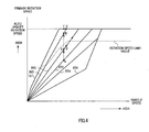
- FIG. 3 is a map showing the relationship between a vehicle speed, a primary rotation speed, and a speed ratio.
- FIG. 4 is a map showing the relationship between a vehicle speed, a primary rotation speed, and a speed ratio.
- FIG. 5 is a flowchart showing control of the speed change control device for an automatic transmission according to a second embodiment.
- FIG. 1 is a schematic diagram showing a speed change control device for an automatic transmission according to an embodiment.
- a belt type continuously variable transmission 10 comprises a primary pulley 11, a secondary pulley 12, a V belt 13, a CVT control unit 20 (CVTCU hereafter), and an oil pressure control unit 30.
- CVT control unit 20 CVT control unit 20
- the primary pulley 11 is an input shaft side pulley which inputs the rotation of an engine 1 into the belt type continuously variable transmission 10.
- the primary pulley 11 comprises a fixed conical plate 11b which rotates integrally with an input shaft 11d, and a movable conical plate 11a which is disposed opposite the fixed conical plate 11b to form a V-shaped pulley groove, and which can be displaced axially by oil pressure acting on a primary pulley cylinder chamber 11c.
- the primary pulley 11 is connected to the engine 1 via a forward-reverse switching mechanism 3 and a torque converter 2 comprising a lockup clutch, and inputs the rotation of the engine 1.
- the rotation speed of the primary pulley 11 is detected by a primary pulley rotation speed sensor 26.
- the belt 13 is wrapped around the primary pulley 11 and secondary pulley 12 such that the rotation of the primary pulley 11 is transmitted to the secondary pulley 12.
- the secondary pulley 12 outputs the rotation transmitted by the belt 13 to a differential 4.
- the secondary pulley 12 comprises a fixed conical plate 12b which rotates integrally with an output shaft 12d, and a movable conical plate 12a which is disposed opposite the fixed conical plate 12b to form a V-shaped pulley groove, and which can be displaced axially in accordance with oil pressure acting on a secondary pulley cylinder chamber 12c.
- the pressure-receiving surface area of the secondary pulley cylinder chamber 12c is set substantially equally to the pressure-receiving surface area of the primary pulley cylinder chamber 11c.
- the secondary pulley 12 is connected to the differential 4 via an idler gear 14 and an idler shaft, and outputs rotation to the differential 4.
- the rotation speed of the secondary pulley 12 is detected by a secondary pulley rotation speed sensor 27.
- the vehicle speed may be calculated from the rotation speed of the secondary pulley 12.
- the CVTCU 20 determines the speed ratio (a value obtained by dividing the effective radius of the secondary pulley 12 by the effective radius of the primary pulley 11) and a contact frictional force on the basis of signals from an inhibitor switch 23, an accelerator pedal position sensor 24, an oil temperature sensor 25, the primary pulley rotation speed sensor 26, the secondary pulley rotation speed sensor 27, and so on, as well as input torque information from an engine control unit 21, by referring to a speed change line prepared in advance, and controls the belt type continuously variable transmission 10 by transmitting commands to the oil pressure control unit 30.
- the oil pressure control unit 30 operates on the basis of the commands from the CVTCU 20.
- the oil pressure control unit 30 causes the movable conical plate 11a and the movable conical plate 12a to reciprocate in a rotary axis direction by supplying oil pressure to the primary pulley 11 and secondary pulley 12.
- the rotation of the engine 1 is input into the belt type continuously variable transmission 10 via the torque converter 2 and the forward-reverse switching mechanism 3, and transmitted from the primary pulley 11 to the differential 4 via the belt 13 and secondary pulley 12.
- the movable conical plate 11a of the primary pulley 11 and the movable conical plate 12a of the secondary pulley 12 are axially displaced, thereby varying the contact radius thereof with the belt 13 such that the speed ratio is varied continuously.
- the speed ratio is set on the basis of a map on which a plurality of speed change lines indicating the relationship between the vehicle speed and the primary rotation speed are prepared for each throttle opening, by looking up a primary rotation speed that corresponds to the vehicle speed and the throttle opening.
- FIG. 2 is a flowchart illustrating the control of the speed change control device for an automatic transmission according to this embodiment. This control is performed repeatedly at brief intervals (of 10ms, for example).
- the routine advances to a step S2, and when it is determined that the manual mode has not been set, the processing is terminated.
- the manual mode is a speed change mode in which a shift schedule corresponding to a plurality of gear positions is prepared in advance such that a driver can perform an operation to switch between each gear position.
- step S2 downshift request determining means
- the routine advances to a step S3, and when it is determined that a kick down command has not been output, the processing is terminated.
- a kick down is a downshift for improving the acceleration performance, and a kick down command may be output on the basis of the vehicle speed and accelerator pedal position, or a kick down switch may be provided such that a kick down command is output when the driver operates the kick down switch.
- step S3 a determination is made as to whether or not the primary rotation speed is lower than a rotation speed limit value (first rotation speed limit value).
- a rotation speed limit value first rotation speed limit value
- an excessively high primary rotation speed causes problems in terms of the durability of the engine 1 and transmission 10, and therefore when the primary rotation speed reaches a predetermined rotation speed, a fuel cut is implemented to protect the engine 1 and transmission 10.
- a fuel cut is implemented to protect the engine 1 and transmission 10.
- an auto upshift rotation speed predetermined high rotation speed
- the rotation speed limit value employed in this step is set to a rotation speed at which the time required for the primary rotation speed to reach the auto upshift rotation speed after exceeding the rotation speed limit value during acceleration is equal to or greater than a predetermined time.
- the predetermined time (first predetermined time) is set to a time which is long enough to ensure that the driver does not feel a sense of discomfort at the interval between a downshift and the auto upshift, and is set in advance through experiment or the like.
- the rotation speed limit value is set such that acceleration produced by a driving force step occurring during a kick down is smaller than a predetermined acceleration upper limit value.
- the predetermined acceleration upper limit value is set in advance through experiment or the like to a value at which the driving force step does not cause the driver to feel a sense of discomfort.
- step S4 rotation speed determining means
- a post-downshift engine rotation speed is predicted.
- a kick down command has been output, and therefore the primary rotation speed at the speed ratio following the kick down is predicted by referring to a speed change diagram such as that shown in FIG. 3, for example.
- the routine advances to a step S6, and when the post-downshift primary rotation speed is smaller than the rotation speed limit value, the routine advances to a step S7.
- step S6 downshift control means
- the lowest gear position among the gear positions at which the primary rotation speed falls below the rotation speed limit value, rather than the gear position indicated by the kick down command is set as a target gear position.
- a gear position higher than the gear position corresponding to the kick down command is set as the target gear position.
- step S7 the gear position indicated by the kick down command is set as the target gear position.
- a step S8 the speed ratio of the transmission 10 is controlled on the basis of the gear position set in the step S6 or the step S7.
- the routine advances to the step S9, where the gear position is held.
- FIGs. 3 and 4 are maps showing a shift schedule of the respective gear positions.
- FIG. 3 shows the prior art, while FIG. 4 shows this embodiment.
- the primary rotation speed is equal to or greater than the rotation speed limit value, and therefore the gear position is not switched and the current gear position is held.
- a downshift is performed to a gear position at which the primary rotation speed is lower than the predicted primary rotation speed, and therefore a situation in which the primary rotation speed reaches the auto upshift rotation speed such that an upshift is performed immediately after the downshift, causing the driver to feel a sense of discomfort due to rapid changes in the gear position, can be prevented.
- a downshift is performed to a gear position at which the primary rotation speed is lower than the rotation speed limit value, and therefore the driver can be prevented from feeling a sense of discomfort due to rapid changes in the gear position.
- the rotation speed limit value is set to a rotation speed at which the time required for the primary rotation speed to reach the auto upshift rotation speed during acceleration is equal to or greater than the predetermined time, and therefore a certain amount of time is required for the primary rotation speed to reach the auto upshift rotation speed, at which an upshift is performed, following a downshift.
- the driver can be prevented from feeling a sense of discomfort due to unnecessarily rapid changes in the gear position.
- the rotation speed limit value is set such that the acceleration produced by a driving force step occurring during a kick down is smaller than the predetermined acceleration upper limit value.
- the constitution of the speed change control device for an automatic transmission is identical to that of the first embodiment, but the control content is different.
- identical parts to those of the first embodiment have been allocated identical reference symbols, and description thereof has been omitted where appropriate.
- FIG. 5 is a flowchart showing the control of the speed change control device for an automatic transmission according to this embodiment. This control is performed repeatedly at brief intervals (of 10ms, for example).
- the routine advances to a step S12, and when it is determined that the manual mode has not been set, the processing is terminated.
- step S12 downshift request determining means
- the routine advances to a step S13, and when it is determined that a downshift operation has not been performed, the processing is terminated.
- a downshift operation performed by the driver is an operation performed by the driver to downshift the gear position.
- step S13 a determination is made as to whether or not the elapsed time from the previous downshift operation performed by the driver is greater than a predetermined time (second predetermined time). If so, the routine advances to a step S14, and if not, the routine advances to a step S18.
- a predetermined time second predetermined time
- the predetermined time is a maximum value of the elapsed time to the next downshift operation when a downshift is not performed following a downshift operation performed by the driver, and is determined in advance through experiment or the like.
- a shift operation performed within the predetermined time is determined to be a downshift operation performed for a second time when the driver senses that the desired gear position has not been achieved by an initial shift operation, and a shift operation performed after the predetermined time is determined to be a new downshift operation separate to the initial shift operation.
- step S14 a determination is made as to whether or not the primary rotation speed is lower than a rotation speed limit value (second rotation speed limit value).
- second rotation speed limit value a rotation speed limit value
- the routine advances to a step S 15 and when it is determined that the primary rotation speed is equal to or greater than the rotation speed limit value, the routine advances to a step S20.
- the rotation speed limit value is set such that acceleration produced by a driving force step occurring during a downshift performed as a result of a downshift operation is smaller than a predetermined acceleration upper limit value.
- the predetermined acceleration upper limit value is determined in advance through experiment or the like to a value at which the driving force step does not cause the driver to feel a sense of discomfort.
- the rotation speed limit value used in this embodiment is set higher than the rotation speed limit value of the first embodiment. This is done so that during a downshift resulting from a driver operation, drivability is improved by prioritizing the driver operation as much as possible.
- step S15 the engine rotation speed following the downshift is predicted.
- the routine advances to a step S17, and when the post-downshift primary rotation speed is smaller than the rotation speed limit value, the routine advances to a step S 18.
- step S 17 downshift control means
- the lowest gear position among the gear positions at which the primary rotation speed falls below the rotation speed limit value, rather than the gear position indicated by the driver is set as a target gear position.
- a gear position higher than the gear position corresponding to the downshift operation performed by the driver is set as the target gear position.
- the routine advances to the step S18, where the gear position based on the downshift operation is set.
- a step S 19 the speed ratio of the transmission is controlled on the basis of the gear position set in the step S 17 or the step S 18.
- the routine advances to a step S20, where the gear position is held.
- the actions of this embodiment will be described.
- the predicted post-downshift primary rotation speed at the driving point B is equal to or greater than the rotation speed limit value, and therefore a downshift is performed to the third speed, which is the lowest gear position among the gear positions at which the primary rotation speed falls below the rotation speed limit value, such that the driving point shifts to the driving point E.
- the rotation speed limit value is set such that the acceleration produced by a driving force step occurring as a result of a downshift operation performed by the driver is smaller than the predetermined acceleration upper limit value.
- a determination is made as to whether or not a kick down request has been output during traveling in the manual speed change mode
- a determination is made as to whether or not a downshift request has been output in accordance with a driver operation.
- both determinations may be made at the same time.
Abstract
Description
- This invention relates to the speed change control of a speed change control device for an automatic transmission, and more particularly speed change control performed in a manual mode.
-
JP10-141485A - In the prior art described above, when a downshift is performed to the vicinity of running conditions at which an auto upshift is performed, the auto upshift is performed immediately thereafter, and the resulting shift busyness makes the driver feel uncomfortable.
- An object of this invention is to suppress the sense of discomfort felt by a driver as a result of shift busyness while maintaining the auto upshift function of the gear position.
- In order to achieve the object, this invention provides a speed change control device for an automatic transmission, including a manual speed change mode in which switching between a plurality of gear positions can be performed in accordance with a driver operation. The device comprising a controller which upshifts a gear position when a rotation speed of an input shaft of the transmission exceeds a predetermined high rotation speed, determines whether or not a request to downshift the gear position of the transmission exists during traveling in the manual speed change mode, calculates the input shaft rotation speed of the transmission following a downshift based on the downshift request, determines whether or not the calculated rotation speed is higher than a rotation speed limit value set on a lower rotation side than the predetermined high rotation speed, and performs a downshift to a gear position at which the input shaft rotation speed of the transmission is lower than the calculated rotation speed when it is determined that the calculated rotation speed is higher than the rotation speed limit value.
- According to this invention, when it is determined that the input shaft rotation speed of the transmission following a downshift is greater than the rotation speed limit value, a downshift is performed to a gear position at which the input shaft rotation speed of the transmission falls below the post-downshift rotation speed, and thus a situation in which the input shaft rotation speed of the transmission reaches an auto upshift rotation speed such that an upshift is performed immediately after the downshift can be prevented. As a result, the sense of discomfort felt by a driver due rapid changes in the gear position can be prevented.
- FIG. 1 is a schematic diagram showing a speed change control device for an automatic transmission according to a first embodiment.
- FIG. 2 is a flowchart showing control of the speed change control device for an automatic transmission according to the first embodiment.
- FIG. 3 is a map showing the relationship between a vehicle speed, a primary rotation speed, and a speed ratio.
- FIG. 4 is a map showing the relationship between a vehicle speed, a primary rotation speed, and a speed ratio.
- FIG. 5 is a flowchart showing control of the speed change control device for an automatic transmission according to a second embodiment.
- Embodiments of this invention will be described in detail below with reference to the drawings and so on.
- (First Embodiment)
- FIG. 1 is a schematic diagram showing a speed change control device for an automatic transmission according to an embodiment. A belt type continuously
variable transmission 10 comprises aprimary pulley 11, asecondary pulley 12, aV belt 13, a CVT control unit 20 (CVTCU hereafter), and an oilpressure control unit 30. - The
primary pulley 11 is an input shaft side pulley which inputs the rotation of an engine 1 into the belt type continuouslyvariable transmission 10. Theprimary pulley 11 comprises a fixedconical plate 11b which rotates integrally with aninput shaft 11d, and a movableconical plate 11a which is disposed opposite the fixedconical plate 11b to form a V-shaped pulley groove, and which can be displaced axially by oil pressure acting on a primarypulley cylinder chamber 11c. Theprimary pulley 11 is connected to the engine 1 via a forward-reverse switching mechanism 3 and atorque converter 2 comprising a lockup clutch, and inputs the rotation of the engine 1. The rotation speed of theprimary pulley 11 is detected by a primary pulleyrotation speed sensor 26. - The
belt 13 is wrapped around theprimary pulley 11 andsecondary pulley 12 such that the rotation of theprimary pulley 11 is transmitted to thesecondary pulley 12. - The
secondary pulley 12 outputs the rotation transmitted by thebelt 13 to adifferential 4. Thesecondary pulley 12 comprises a fixedconical plate 12b which rotates integrally with anoutput shaft 12d, and a movableconical plate 12a which is disposed opposite the fixedconical plate 12b to form a V-shaped pulley groove, and which can be displaced axially in accordance with oil pressure acting on a secondarypulley cylinder chamber 12c. It should be noted that the pressure-receiving surface area of the secondarypulley cylinder chamber 12c is set substantially equally to the pressure-receiving surface area of the primarypulley cylinder chamber 11c. - The
secondary pulley 12 is connected to thedifferential 4 via anidler gear 14 and an idler shaft, and outputs rotation to thedifferential 4. The rotation speed of thesecondary pulley 12 is detected by a secondary pulleyrotation speed sensor 27. The vehicle speed may be calculated from the rotation speed of thesecondary pulley 12. - The CVTCU 20 determines the speed ratio (a value obtained by dividing the effective radius of the
secondary pulley 12 by the effective radius of the primary pulley 11) and a contact frictional force on the basis of signals from aninhibitor switch 23, an acceleratorpedal position sensor 24, anoil temperature sensor 25, the primary pulleyrotation speed sensor 26, the secondary pulleyrotation speed sensor 27, and so on, as well as input torque information from anengine control unit 21, by referring to a speed change line prepared in advance, and controls the belt type continuouslyvariable transmission 10 by transmitting commands to the oilpressure control unit 30. - The oil
pressure control unit 30 operates on the basis of the commands from the CVTCU 20. The oilpressure control unit 30 causes the movableconical plate 11a and the movableconical plate 12a to reciprocate in a rotary axis direction by supplying oil pressure to theprimary pulley 11 andsecondary pulley 12. - When the movable
conical plate 11 a and the movableconical plate 12a move, the pulley groove width varies, and as a result, thebelt 13 moves over theprimary pulley 11 andsecondary pulley 12. Thus, the contact radius between thebelt 13 and theprimary pulley 11 andsecondary pulley 12 varies, whereby the speed ratio and the contact frictional force of thebelt 13 are controlled. - The rotation of the engine 1 is input into the belt type continuously
variable transmission 10 via thetorque converter 2 and the forward-reverse switching mechanism 3, and transmitted from theprimary pulley 11 to thedifferential 4 via thebelt 13 andsecondary pulley 12. - When the accelerator pedal is depressed or a shift change is performed in a manual mode, the movable
conical plate 11a of theprimary pulley 11 and the movableconical plate 12a of thesecondary pulley 12 are axially displaced, thereby varying the contact radius thereof with thebelt 13 such that the speed ratio is varied continuously. - The speed ratio is set on the basis of a map on which a plurality of speed change lines indicating the relationship between the vehicle speed and the primary rotation speed are prepared for each throttle opening, by looking up a primary rotation speed that corresponds to the vehicle speed and the throttle opening.
- The control performed by the CVTCU 20 will now be described with reference to the flowchart in FIG. 2. FIG. 2 is a flowchart illustrating the control of the speed change control device for an automatic transmission according to this embodiment. This control is performed repeatedly at brief intervals (of 10ms, for example).
- In a step S1, a determination is made as to whether or not a speed change mode is set to a manual mode. When it is determined that the manual mode has been set, the routine advances to a step S2, and when it is determined that the manual mode has not been set, the processing is terminated. Here, the manual mode is a speed change mode in which a shift schedule corresponding to a plurality of gear positions is prepared in advance such that a driver can perform an operation to switch between each gear position.
- In the step S2 (downshift request determining means), a determination is made as to whether or not a kick down command has been output. When it is determined that a kick down command has been output, the routine advances to a step S3, and when it is determined that a kick down command has not been output, the processing is terminated. A kick down is a downshift for improving the acceleration performance, and a kick down command may be output on the basis of the vehicle speed and accelerator pedal position, or a kick down switch may be provided such that a kick down command is output when the driver operates the kick down switch.
- In the step S3, a determination is made as to whether or not the primary rotation speed is lower than a rotation speed limit value (first rotation speed limit value). When it is determined that the primary rotation speed is lower than the rotation speed limit value, the routine advances to a step S4, and when it is determined that the primary rotation speed is equal to or higher than the rotation speed limit value, the routine advances to a step S9.
- Here, an excessively high primary rotation speed causes problems in terms of the durability of the engine 1 and
transmission 10, and therefore when the primary rotation speed reaches a predetermined rotation speed, a fuel cut is implemented to protect the engine 1 andtransmission 10. However, when a fuel cut is implemented, the driving force of the engine falls rapidly and the drivability deteriorates. To prevent this, an auto upshift rotation speed (predetermined high rotation speed) is set as a threshold for forcibly shifting the gear position to the up side (auto upshift means) before the primary rotation speed reaches a fuel cut rotation speed. - The rotation speed limit value employed in this step is set to a rotation speed at which the time required for the primary rotation speed to reach the auto upshift rotation speed after exceeding the rotation speed limit value during acceleration is equal to or greater than a predetermined time. The predetermined time (first predetermined time) is set to a time which is long enough to ensure that the driver does not feel a sense of discomfort at the interval between a downshift and the auto upshift, and is set in advance through experiment or the like.
- Furthermore, when the vehicle speed is comparatively low and a speed change is performed at a high primary rotation speed, a driving force step is likely to occur, and therefore the rotation speed limit value is set such that acceleration produced by a driving force step occurring during a kick down is smaller than a predetermined acceleration upper limit value. The predetermined acceleration upper limit value is set in advance through experiment or the like to a value at which the driving force step does not cause the driver to feel a sense of discomfort.
- In the step S4 (rotation speed determining means), a post-downshift engine rotation speed is predicted. During execution of this step, a kick down command has been output, and therefore the primary rotation speed at the speed ratio following the kick down is predicted by referring to a speed change diagram such as that shown in FIG. 3, for example.
- In a step S5 (rotation speed determining means), a determination is made as to whether or not the post-downshift primary rotation speed predicted in the step S4 is equal to or greater than the rotation speed limit value. When the post-downshift primary rotation speed is equal to or greater than the rotation speed limit value, the routine advances to a step S6, and when the post-downshift primary rotation speed is smaller than the rotation speed limit value, the routine advances to a step S7.
- In the step S6 (downshift control means), the lowest gear position among the gear positions at which the primary rotation speed falls below the rotation speed limit value, rather than the gear position indicated by the kick down command, is set as a target gear position. As a result, a gear position higher than the gear position corresponding to the kick down command is set as the target gear position.
- In the step S7, on the other hand, the gear position indicated by the kick down command is set as the target gear position.
- In a step S8, the speed ratio of the
transmission 10 is controlled on the basis of the gear position set in the step S6 or the step S7. - Meanwhile, when it is determined in the step S3 that the primary rotation speed is equal to or higher than the rotation speed limit value, the routine advances to the step S9, where the gear position is held.
- Next, referring to the maps in FIGs. 3 and 4, the actions of this embodiment will be described. FIGs. 3 and 4 are maps showing a shift schedule of the respective gear positions. FIG. 3 shows the prior art, while FIG. 4 shows this embodiment.
- First, the prior art will be described with reference to FIG. 3. In the manual mode, when a kick down command instructing a kick down to a second speed is output at a driving point A during acceleration in a fourth speed, a downshift is performed to the second speed such that the driving point shifts to a driving point B. When acceleration continues thereafter such that the auto upshift rotation speed is reached at a driving point C, an upshift is performed to a third speed such that the driving point shifts to a driving point D. Thus in the prior art, an upshift is performed immediately after a downshift, and as a result the drivability deteriorates.
- Next, this embodiment will be described with reference to FIG. 4. In the manual mode, when a kick down command instructing a kick down to the second speed is output at the driving point A during traveling in the fourth speed, the predicted post-downshift primary rotation speed at the driving point B is equal to or greater than the rotation speed limit value. Therefore, a downshift is performed to a third speed, which is the lowest gear position among the gear positions at which the primary rotation speed falls below the rotation speed limit value, and the driving point shifts to a driving point E. Thus, a situation in which an upshift is performed immediately after a downshift can be avoided.
- Further, when a kick down command is output during acceleration at the driving point B, the primary rotation speed is equal to or greater than the rotation speed limit value, and therefore the gear position is not switched and the current gear position is held.
- In the embodiment described above, when it is determined that the predicted primary rotation speed following a downshift is greater than the rotation speed limit value, a downshift is performed to a gear position at which the primary rotation speed is lower than the predicted primary rotation speed, and therefore a situation in which the primary rotation speed reaches the auto upshift rotation speed such that an upshift is performed immediately after the downshift, causing the driver to feel a sense of discomfort due to rapid changes in the gear position, can be prevented.
- Further, when it is determined that the predicted primary rotation speed following a downshift is greater than the rotation speed limit value, a downshift is performed to a gear position at which the primary rotation speed is lower than the rotation speed limit value, and therefore the driver can be prevented from feeling a sense of discomfort due to rapid changes in the gear position.
- Moreover, the rotation speed limit value is set to a rotation speed at which the time required for the primary rotation speed to reach the auto upshift rotation speed during acceleration is equal to or greater than the predetermined time, and therefore a certain amount of time is required for the primary rotation speed to reach the auto upshift rotation speed, at which an upshift is performed, following a downshift. As a result, the driver can be prevented from feeling a sense of discomfort due to unnecessarily rapid changes in the gear position.
- Furthermore, a determination is made as to whether or not a kick down command has been output as a downshift request, and therefore a situation in which the primary rotation speed reaches the auto upshift rotation speed immediately after a kick down such that an upshift is performed, causing the driver to feel a sense of discomfort at the rapidly changing gear position, can be prevented.
- Moreover, if it is determined that the primary rotation speed is equal to or greater than the rotation speed limit value when a kick down command is output, a downshift is prohibited and the gear position is held. Thus, a situation in which a kick down is performed when the primary rotation speed is in the vicinity of the auto upshift rotation speed such that an auto upshift is performed immediately thereafter, causing the driver to feel a sense of discomfort at the rapidly changing gear position, can be prevented.
- Further, the rotation speed limit value is set such that the acceleration produced by a driving force step occurring during a kick down is smaller than the predetermined acceleration upper limit value. Hence, a situation in which the driver feels a sense of discomfort based on the driving force step in addition to the sense of discomfort caused by unnecessary changes in the gear position can be prevented.
- (Second Embodiment)
- In this embodiment, the constitution of the speed change control device for an automatic transmission is identical to that of the first embodiment, but the control content is different. Below, identical parts to those of the first embodiment have been allocated identical reference symbols, and description thereof has been omitted where appropriate.
- Referring to the flowchart in FIG. 5, the control performed by the
CVTCU 20 according to this embodiment will be described. FIG. 5 is a flowchart showing the control of the speed change control device for an automatic transmission according to this embodiment. This control is performed repeatedly at brief intervals (of 10ms, for example). - In a step S11, a determination is made as to whether or not the speed change mode is set to the manual mode. When it is determined that the manual mode has been set, the routine advances to a step S12, and when it is determined that the manual mode has not been set, the processing is terminated.
- In the step S12 (downshift request determining means), a determination is made as to whether or not a downshift operation has been performed by the driver. When it is determined that a downshift operation has been performed by the driver, the routine advances to a step S13, and when it is determined that a downshift operation has not been performed, the processing is terminated. A downshift operation performed by the driver is an operation performed by the driver to downshift the gear position.
- In the step S13, a determination is made as to whether or not the elapsed time from the previous downshift operation performed by the driver is greater than a predetermined time (second predetermined time). If so, the routine advances to a step S14, and if not, the routine advances to a step S18.
- The predetermined time is a maximum value of the elapsed time to the next downshift operation when a downshift is not performed following a downshift operation performed by the driver, and is determined in advance through experiment or the like. Hence, a shift operation performed within the predetermined time is determined to be a downshift operation performed for a second time when the driver senses that the desired gear position has not been achieved by an initial shift operation, and a shift operation performed after the predetermined time is determined to be a new downshift operation separate to the initial shift operation.
- In the step S14, a determination is made as to whether or not the primary rotation speed is lower than a rotation speed limit value (second rotation speed limit value). When it is determined that the primary rotation speed is lower than the rotation speed limit value, the routine advances to a
step S 15, and when it is determined that the primary rotation speed is equal to or greater than the rotation speed limit value, the routine advances to a step S20. - Here, the rotation speed limit value is set such that acceleration produced by a driving force step occurring during a downshift performed as a result of a downshift operation is smaller than a predetermined acceleration upper limit value. The predetermined acceleration upper limit value is determined in advance through experiment or the like to a value at which the driving force step does not cause the driver to feel a sense of discomfort.
- The rotation speed limit value used in this embodiment is set higher than the rotation speed limit value of the first embodiment. This is done so that during a downshift resulting from a driver operation, drivability is improved by prioritizing the driver operation as much as possible.
- In the step S15 (rotation speed determining means), the engine rotation speed following the downshift is predicted.
- In a step S16 (rotation speed determining means), a determination is made as to whether or not the post-downshift primary rotation speed predicted in the step S15 is equal to or greater than the rotation speed limit value. When the post-downshift primary rotation speed is equal to or greater than the rotation speed limit value, the routine advances to a step S17, and when the post-downshift primary rotation speed is smaller than the rotation speed limit value, the routine advances to a step S 18.
- In the step S 17 (downshift control means), the lowest gear position among the gear positions at which the primary rotation speed falls below the rotation speed limit value, rather than the gear position indicated by the driver, is set as a target gear position. As a result, a gear position higher than the gear position corresponding to the downshift operation performed by the driver is set as the target gear position.
- Meanwhile, when it is determined in the step S13 that the elapsed time following the previous downshift operation by the driver is equal to or smaller than the predetermined time, or when it is determined in the step S16 that the post-downshift primary rotation speed is equal to or smaller than the rotation speed limit value, the routine advances to the step S18, where the gear position based on the downshift operation is set.
- In a
step S 19, the speed ratio of the transmission is controlled on the basis of the gear position set in the step S 17 or the step S 18. - Meanwhile, when it is determined in the step S 14 that the primary rotation speed is equal to or greater than the rotation speed limit value, the routine advances to a step S20, where the gear position is held.
- Next, referring to the map in FIG. 4, the actions of this embodiment will be described. In the manual mode, when a downshift operation instructing a downshift to the second speed is performed by the driver at the driving point A during traveling in the fourth speed, the predicted post-downshift primary rotation speed at the driving point B is equal to or greater than the rotation speed limit value, and therefore a downshift is performed to the third speed, which is the lowest gear position among the gear positions at which the primary rotation speed falls below the rotation speed limit value, such that the driving point shifts to the driving point E.
- At this time, when another downshift operation is performed by the driver within the predetermined time from the previous downshift operation, the rotation speed limit value is ignored and a downshift is performed to the second speed, as shown by the dotted line arrow in FIG. 4, such that the driving point shifts to the driving point B.
- When a downshift operation is performed by the driver during acceleration at the driving point B, the primary rotation speed is equal to or greater than the rotation speed limit value, and therefore the gear position is not switched and the current gear position is held.
- At this time, when another downshift operation is performed by the driver within the predetermined time from the previous downshift operation, the rotation speed limit value is ignored and a downshift is performed to a first speed such that the driving point shifts to a driving point F.
- In the embodiment described above, a determination is made as to whether or not a downshift operation has been performed by the driver as a downshift request, and hence, in addition to the effects of the first embodiment, a situation in which the primary rotation speed reaches the auto upshift rotation speed such that an upshift is performed immediately after a downshift performed in accordance with a driver operation, causing the driver to feel a sense of discomfort due to rapid changes in the gear position, can be prevented.
- Moreover, when it is determined that the primary rotation speed is equal to or greater than the rotation speed limit value following a downshift operation performed by the driver, a downshift is prohibited and the gear position is held. Thus, a situation in which the driver performs a downshift operation when the primary rotation speed is in the vicinity of the auto upshift rotation speed such that an auto upshift is performed immediately thereafter, causing the driver to feel a sense of discomfort due to rapid changes in the gear position, can be prevented.
- Further, the rotation speed limit value is set such that the acceleration produced by a driving force step occurring as a result of a downshift operation performed by the driver is smaller than the predetermined acceleration upper limit value. Hence, a situation in which the driver feels a sense of discomfort based on the driving force step in addition to the sense of discomfort caused by unnecessary changes in the gear position can be prevented.
- This invention is not limited to the embodiments described above, and may be subjected to various alterations and modifications within the technical scope thereof.
- For example, in the first embodiment, a determination is made as to whether or not a kick down request has been output during traveling in the manual speed change mode, whereas in the second embodiment, a determination is made as to whether or not a downshift request has been output in accordance with a driver operation. However, both determinations may be made at the same time.
- In so doing, it is possible to avoid both a situation in which the primary rotation speed reaches the auto upshift rotation speed such that an upshift is performed immediately after a kick down, and a situation in which the primary rotation speed reaches the auto upshift rotation speed such that an upshift is performed immediately after a downshift performed as a result of a driver operation, and hence the driver can be prevented from feeling a sense of discomfort due to rapid changes in the gear position.
- This application claims priority from
Japanese Patent Application 2006-90318, filed March 29, 2006
Claims (16)
- A speed change control device for an automatic transmission (10), including a manual speed change mode in which switching between a plurality of gear positions can be performed in accordance with a driver operation, the device comprising:auto upshift means for upshifting a gear position when a rotation speed of an input shaft of the transmission (10) exceeds a predetermined high rotation speed;downshift request determining means for determining whether or not a request to downshift the gear position of the transmission (10) exists during traveling in the manual speed change mode;rotation speed determining means for calculating the input shaft rotation speed of the transmission (10) following a downshift based on the downshift request, and determining whether or not the calculated rotation speed is higher than a rotation speed limit value set on a lower rotation side than the predetermined high rotation speed; anddownshift control means for performing a downshift to a gear position at which the input shaft rotation speed of the transmission (10) is lower than the calculated rotation speed when it is determined that the calculated rotation speed is higher than the rotation speed limit value.
- The speed change control device as defined in Claim 1, wherein the downshift control means performs a downshift to a gear position at which the input shaft rotation speed of the transmission (10) is lower than the rotation speed limit value when it is determined that the calculated rotation speed is higher than the rotation speed limit value.
- The speed change control device as defined in Claim 1 or Claim 2, wherein the rotation speed limit value is set such that a time required for the input shaft rotation speed of the transmission (10) to exceed the predetermined high rotation speed after exceeding the rotation speed limit value following a downshift based on the downshift request is equal to or greater than a first predetermined time.
- The speed change control device as defined in any one of Claim 1 through Claim 3, wherein the downshift request determining means determines at least one of whether or not a request to perform a kick down exists during traveling in the manual speed change mode and whether or not a request to perform a downshift in accordance with a driver operation exists during traveling in the manual speed change mode.
- The speed change control device as defined in any one of Claim 1 through Claim 3, wherein
the downshift request determining means determines whether or not a request to perform a kick down exists during traveling in the manual speed change mode and whether or not a request to perform a downshift in accordance with a driver operation exists during traveling in the manual speed change mode, and
the rotation speed determining means determines whether or not the calculated rotation speed is higher than a first rotation speed limit value when a kick down is performed during traveling in the manual speed change mode, and determines whether or not the calculated rotation speed is higher than a second rotation speed limit value when a downshift is performed on the basis of a downshift request in accordance with a driver operation during traveling in the manual speed change mode, the second rotation speed limit value being higher than the first rotation speed limit value. - The speed change control device as defined in any one of Claim 1 through Claim 5, wherein, when it is determined that a request to downshift the gear position of the transmission (10) exists during traveling in the manual speed change mode and the input shaft rotation speed of the transmission (10) is higher than the rotation speed limit value, the downshift control means prohibits downshifting regardless of the determination result of the rotation speed determining means.
- The speed change control device as defined in Claim 4 or Claim 5, wherein, when it is determined that a request to perform a downshift in accordance with a driver operation exists and an elapsed time following a previous driver operation is shorter than a second predetermined time, the downshift control means performs a downshift based on the downshift request regardless of the determination result of the rotation speed determining means.
- The speed change control device as defined in any one of Claim 1 through Claim 7, wherein the rotation speed limit value is set such that an acceleration produced by a driving force step occurring when a downshift is performed on the basis of the downshift request is smaller than a predetermined acceleration upper limit value.
- A speed change control method for an automatic transmission (10), including a manual speed change mode in which switching between a plurality of gear positions can be performed in accordance with a driver operation, the method comprising:upshifting a gear position when a rotation speed of an input shaft of the transmission (10) exceeds a predetermined high rotation speed;determining whether or not a request to downshift the gear position of the transmission (10) exists during traveling in the manual speed change mode;calculating the input shaft rotation speed of the transmission (10) following a downshift based on the downshift request;determining whether or not the calculated rotation speed is higher than a rotation speed limit value set on a lower rotation side than the predetermined high rotation speed; andperforming a downshift to a gear position at which the input shaft rotation speed of the transmission (10) is lower than the calculated rotation speed when it is determined that the calculated rotation speed is higher than the rotation speed limit value.
- The speed change control method as defined in Claim 9, wherein the performing a downshift performs a downshift to a gear position at which the input shaft rotation speed of the transmission (10) is lower than the rotation speed limit value when it is determined that the calculated rotation speed is higher than the rotation speed limit value.
- The speed change control method as defined in Claim 9 or Claim 10, wherein the rotation speed limit value is set such that a time required for the input shaft rotation speed of the transmission (10) to exceed the predetermined high rotation speed after exceeding the rotation speed limit value following a downshift based on the downshift request is equal to or greater than a first predetermined time.
- The speed change control method as defined in any one of Claim 9 through Claim 11, wherein the determining whether or not the request to downshift the gear position of the transmission (10) exists determines at least one of whether or not a request to perform a kick down exists during traveling in the manual speed change mode and whether or not a request to perform a downshift in accordance with a driver operation exists during traveling in the manual speed change mode.
- The speed change control method as defined in any one of Claim 9 through Claim 11, wherein
the determining whether or not the request to downshift the gear position of the transmission ( 10) exists determines whether or not a request to perform a kick down exists during traveling in the manual speed change mode and whether or not a request to perform a downshift in accordance with a driver operation exists during traveling in the manual speed change mode, and
the determining whether or not the calculated rotation speed is higher than the rotation speed limit value determines whether or not the calculated rotation speed is higher than a first rotation speed limit value when a kick down is performed during traveling in the manual speed change mode, and determines whether or not the calculated rotation speed is higher than a second rotation speed limit value when a downshift is performed on the basis of a downshift request in accordance with a driver operation during traveling in the manual speed change mode, the second rotation speed limit value being higher than the first rotation speed limit value. - The speed change control method as defined in any one of Claim 9 through Claim 13, wherein, when it is determined that a request to downshift the gear position of the transmission (10) exists during traveling in the manual speed change mode and the input shaft rotation speed of the transmission (10) is higher than the rotation speed limit value, the performing a downshift prohibits downshifting regardless of the determination result of the determining whether or not the calculated rotation speed is higher than the rotation speed limit value.
- The speed change control method as defined in Claim 12 or Claim 13, wherein, when it is determined that a request to perform a downshift in accordance with a driver operation exists and an elapsed time following a previous driver operation is shorter than a second predetermined time, the performing a downshift performs a downshift based on the downshift request regardless of the determination result of the determining whether or not the calculated rotation speed is higher than the rotation speed limit value.
- The speed change control method as defined in Claim 9 or Claim 15, wherein the rotation speed limit value is set such that an acceleration produced by a driving force step occurring when a downshift is performed on the basis of the downshift request is smaller than a predetermined acceleration upper limit value.
Applications Claiming Priority (1)
| Application Number | Priority Date | Filing Date | Title |
|---|---|---|---|
| JP2006090318A JP4584856B2 (en) | 2006-03-29 | 2006-03-29 | Shift control device for automatic transmission |
Publications (3)
| Publication Number | Publication Date |
|---|---|
| EP1840415A2 true EP1840415A2 (en) | 2007-10-03 |
| EP1840415A3 EP1840415A3 (en) | 2010-08-25 |
| EP1840415B1 EP1840415B1 (en) | 2011-09-28 |
Family
ID=38291188
Family Applications (1)
| Application Number | Title | Priority Date | Filing Date |
|---|---|---|---|
| EP07006312A Active EP1840415B1 (en) | 2006-03-29 | 2007-03-27 | Speed change control device for automatic transmission and control method thereof |
Country Status (4)
| Country | Link |
|---|---|
| US (1) | US7862474B2 (en) |
| EP (1) | EP1840415B1 (en) |
| JP (1) | JP4584856B2 (en) |
| CN (1) | CN100523561C (en) |
Cited By (2)
| Publication number | Priority date | Publication date | Assignee | Title |
|---|---|---|---|---|
| WO2013054530A1 (en) * | 2011-10-13 | 2013-04-18 | Toyota Jidosha Kabushiki Kaisha | Vehicular control apparatus |
| CN104879483A (en) * | 2015-04-21 | 2015-09-02 | 常州东风无级变速器有限公司 | Continuously variable transmission with high function security and power machinery with continuously variable transmission |
Families Citing this family (20)
| Publication number | Priority date | Publication date | Assignee | Title |
|---|---|---|---|---|
| US8596398B2 (en) * | 2007-05-16 | 2013-12-03 | Polaris Industries Inc. | All terrain vehicle |
| JP4650496B2 (en) * | 2008-02-15 | 2011-03-16 | トヨタ自動車株式会社 | Control device for automatic transmission for vehicle |
| JP5232565B2 (en) * | 2008-08-04 | 2013-07-10 | アイシン・エーアイ株式会社 | Dual clutch transmission |
| JP4951658B2 (en) * | 2009-09-02 | 2012-06-13 | ジヤトコ株式会社 | Control device for automatic transmission |
| JP4920064B2 (en) * | 2009-09-02 | 2012-04-18 | ジヤトコ株式会社 | Control device for automatic transmission |
| EP2529989B1 (en) * | 2010-01-27 | 2016-09-21 | Toyota Jidosha Kabushiki Kaisha | Vehicle and control method thereof |
| JP5310597B2 (en) * | 2010-02-23 | 2013-10-09 | 日本精工株式会社 | Continuously variable transmission |
| CN102116369A (en) * | 2010-07-22 | 2011-07-06 | 浙江吉利汽车研究院有限公司 | Method for controlling manual gear shift of automatic transmission |
| JP5266302B2 (en) * | 2010-12-08 | 2013-08-21 | 富士重工業株式会社 | Shift control device for automatic transmission |
| US10371259B2 (en) * | 2013-10-08 | 2019-08-06 | Jatco Ltd | Control device for continuously variable transmission equipped with auxiliary transmission |
| KR101873136B1 (en) * | 2014-03-03 | 2018-06-29 | 쟈트코 가부시키가이샤 | Control device for continuously variable transmission for use in vehicles |
| JP6197099B2 (en) | 2014-03-03 | 2017-09-27 | ジヤトコ株式会社 | Control device for continuously variable transmission for vehicle |
| KR101893712B1 (en) * | 2014-08-05 | 2018-08-30 | 쟈트코 가부시키가이샤 | Controller for continuously variable transmission |
| JP6565029B2 (en) * | 2014-09-30 | 2019-08-28 | ダイハツ工業株式会社 | Control device for automatic transmission |
| CN105179682B (en) * | 2015-08-25 | 2017-08-25 | 重庆长安汽车股份有限公司 | The shift control method and system of a kind of two gears transmission vehicle |
| JP6321063B2 (en) * | 2016-02-29 | 2018-05-09 | 能美防災株式会社 | Fire monitoring system and smoke detector |
| US9708985B1 (en) * | 2016-04-19 | 2017-07-18 | Hyundai America Technical Center, Inc. | Matching torque map to shift pattern |
| JP6630713B2 (en) * | 2017-11-02 | 2020-01-15 | 本田技研工業株式会社 | Vehicle shift control device |
| JP7242137B2 (en) * | 2019-03-15 | 2023-03-20 | ジヤトコ株式会社 | Gear control device for continuously variable transmission |
| JP2020148309A (en) * | 2019-03-15 | 2020-09-17 | ジヤトコ株式会社 | Shift control device of continuously variable transmission |
Citations (4)
| Publication number | Priority date | Publication date | Assignee | Title |
|---|---|---|---|---|
| JPH09264415A (en) * | 1996-03-29 | 1997-10-07 | Mazda Motor Corp | Control device for automatic transmission |
| DE19740648A1 (en) * | 1996-09-19 | 1998-03-26 | Jatco Corp | Automatic drive transmission |
| DE19740647A1 (en) * | 1996-09-19 | 1998-03-26 | Jatco Corp | Motor vehicle automatic drive transmission |
| DE10151909A1 (en) * | 2001-10-20 | 2003-04-30 | Zahnradfabrik Friedrichshafen | Procedure for triggering an upshift on kick-down |
Family Cites Families (12)
| Publication number | Priority date | Publication date | Assignee | Title |
|---|---|---|---|---|
| JP2594713Y2 (en) * | 1993-04-08 | 1999-05-10 | 日産ディーゼル工業株式会社 | Transmission for vehicles |
| US5623408A (en) * | 1995-03-03 | 1997-04-22 | Saturn Corporation | Cruise control inference based shift pattern control |
| JP3322110B2 (en) * | 1996-02-15 | 2002-09-09 | 日産自動車株式会社 | Transmission control device for continuously variable transmission |
| JP3513314B2 (en) * | 1996-02-20 | 2004-03-31 | 富士重工業株式会社 | Control device for continuously variable transmission for vehicles |
| JP3638389B2 (en) | 1996-11-05 | 2005-04-13 | 本田技研工業株式会社 | Control device for automatic transmission for vehicle |
| US6146310A (en) * | 1999-01-15 | 2000-11-14 | Eaton Corporation | Adaptive automated transmission downshift control |
| JP2002048226A (en) * | 2000-08-02 | 2002-02-15 | Jatco Transtechnology Ltd | Variable speed control device for automatic transmission |
| US6409628B1 (en) * | 2000-09-29 | 2002-06-25 | Caterpillar Inc. | Method and apparatus for preventing hunting between ranges in a continuously variable transmission |
| JP2003120799A (en) * | 2001-10-15 | 2003-04-23 | Shimano Inc | Speed change control device for bicycle |
| JP3659212B2 (en) * | 2001-10-22 | 2005-06-15 | 日産自動車株式会社 | Automatic clutch control device for gear transmission |
| JP3738740B2 (en) * | 2002-03-19 | 2006-01-25 | 日産自動車株式会社 | Twin clutch gear transmission |
| JP2005291111A (en) * | 2004-03-31 | 2005-10-20 | Jatco Ltd | Input torque control device for belt type continuously variable transmission for vehicle |
-
2006
- 2006-03-29 JP JP2006090318A patent/JP4584856B2/en active Active
-
2007
- 2007-03-27 EP EP07006312A patent/EP1840415B1/en active Active
- 2007-03-28 US US11/727,706 patent/US7862474B2/en active Active
- 2007-03-29 CN CNB2007100869943A patent/CN100523561C/en active Active
Patent Citations (4)
| Publication number | Priority date | Publication date | Assignee | Title |
|---|---|---|---|---|
| JPH09264415A (en) * | 1996-03-29 | 1997-10-07 | Mazda Motor Corp | Control device for automatic transmission |
| DE19740648A1 (en) * | 1996-09-19 | 1998-03-26 | Jatco Corp | Automatic drive transmission |
| DE19740647A1 (en) * | 1996-09-19 | 1998-03-26 | Jatco Corp | Motor vehicle automatic drive transmission |
| DE10151909A1 (en) * | 2001-10-20 | 2003-04-30 | Zahnradfabrik Friedrichshafen | Procedure for triggering an upshift on kick-down |
Cited By (2)
| Publication number | Priority date | Publication date | Assignee | Title |
|---|---|---|---|---|
| WO2013054530A1 (en) * | 2011-10-13 | 2013-04-18 | Toyota Jidosha Kabushiki Kaisha | Vehicular control apparatus |
| CN104879483A (en) * | 2015-04-21 | 2015-09-02 | 常州东风无级变速器有限公司 | Continuously variable transmission with high function security and power machinery with continuously variable transmission |
Also Published As
| Publication number | Publication date |
|---|---|
| US20070232443A1 (en) | 2007-10-04 |
| EP1840415A3 (en) | 2010-08-25 |
| JP4584856B2 (en) | 2010-11-24 |
| CN100523561C (en) | 2009-08-05 |
| US7862474B2 (en) | 2011-01-04 |
| EP1840415B1 (en) | 2011-09-28 |
| CN101046251A (en) | 2007-10-03 |
| JP2007263262A (en) | 2007-10-11 |
Similar Documents
| Publication | Publication Date | Title |
|---|---|---|
| EP1840415B1 (en) | Speed change control device for automatic transmission and control method thereof | |
| US8657720B2 (en) | Shift control apparatus for continuously variable transmission | |
| EP2275713B1 (en) | Shift control of continuously variable transmission | |
| EP2428711A2 (en) | Continuously variable transmission and power on/off determination method | |
| US9671017B2 (en) | Shift control device for continuously variable transmission | |
| JP3211737B2 (en) | Gear ratio control device for continuously variable transmission | |
| JP4109426B2 (en) | Shift control device for automatic transmission | |
| EP1291559A2 (en) | Shift control system for automatic transmission | |
| CN111868417B (en) | Control device and control method for continuously variable transmission | |
| EP3315823A1 (en) | Transmission and transmission control method | |
| EP1811209B1 (en) | Speed change control device for belt type continuously variable transmission (CVT) | |
| US11535229B2 (en) | Control device for vehicle and control method for vehicle | |
| JPH11344108A (en) | Control device for automatic transmission | |
| JPH09264414A (en) | Control device for vehicular automatic transmission | |
| JP7064621B2 (en) | Vehicle control device and vehicle control method | |
| JP4367188B2 (en) | Control device for belt type continuously variable transmission | |
| KR101966536B1 (en) | Method for controlling reverse driving of continuously variable transmission | |
| KR100384006B1 (en) | Method for shift controling of automatic transmission in vehicle | |
| JP2009014105A (en) | Control device of vehicular continuously variable transmission | |
| JP2007032688A (en) | Control device of continuously variable transmission | |
| KR100405667B1 (en) | Kickdown 2 to 1 shift control method of automatic transmission | |
| JP2002089675A (en) | Variable speed control device of automatic transmission | |
| JP2006275226A (en) | Shift control device of automatic transmission | |
| JP2005201320A (en) | Shift control device for continuously variable transmission | |
| JP2006071005A (en) | Continuously variable transmission |
Legal Events
| Date | Code | Title | Description |
|---|---|---|---|
| PUAI | Public reference made under article 153(3) epc to a published international application that has entered the european phase |
Free format text: ORIGINAL CODE: 0009012 |
|
| 17P | Request for examination filed |
Effective date: 20070810 |
|
| AK | Designated contracting states |
Kind code of ref document: A2 Designated state(s): AT BE BG CH CY CZ DE DK EE ES FI FR GB GR HU IE IS IT LI LT LU LV MC MT NL PL PT RO SE SI SK TR |
|
| AX | Request for extension of the european patent |
Extension state: AL BA HR MK YU |
|
| PUAL | Search report despatched |
Free format text: ORIGINAL CODE: 0009013 |
|
| AK | Designated contracting states |
Kind code of ref document: A3 Designated state(s): AT BE BG CH CY CZ DE DK EE ES FI FR GB GR HU IE IS IT LI LT LU LV MC MT NL PL PT RO SE SI SK TR |
|
| AX | Request for extension of the european patent |
Extension state: AL BA HR MK RS |
|
| AKX | Designation fees paid |
Designated state(s): DE FR GB |
|
| GRAP | Despatch of communication of intention to grant a patent |
Free format text: ORIGINAL CODE: EPIDOSNIGR1 |
|
| RIC1 | Information provided on ipc code assigned before grant |
Ipc: F16H 59/42 20060101AFI20110405BHEP |
|
| RIN1 | Information on inventor provided before grant (corrected) |
Inventor name: KOBAYASHI, ATSUFUMIC/O JATCO LTD. Inventor name: WAKABAYASHI, SHUICHIC/O JATCO LTD. Inventor name: MAKIYAMA, AKIHIROC/O NISSAN MOTOR CO.,LTD. Inventor name: OCHIAI, TATSUOC/O JATCO LTD. Inventor name: KIMURA, YUSUKEC/O JATCO LTD. Inventor name: KADONO, RYOJIC/O NISSAN MOTOR CO.,LTD. |
|
| GRAS | Grant fee paid |
Free format text: ORIGINAL CODE: EPIDOSNIGR3 |
|
| GRAA | (expected) grant |
Free format text: ORIGINAL CODE: 0009210 |
|
| AK | Designated contracting states |
Kind code of ref document: B1 Designated state(s): DE FR GB |
|
| REG | Reference to a national code |
Ref country code: GB Ref legal event code: FG4D |
|
| REG | Reference to a national code |
Ref country code: DE Ref legal event code: R096 Ref document number: 602007017450 Country of ref document: DE Effective date: 20111215 |
|
| PLBE | No opposition filed within time limit |
Free format text: ORIGINAL CODE: 0009261 |
|
| STAA | Information on the status of an ep patent application or granted ep patent |
Free format text: STATUS: NO OPPOSITION FILED WITHIN TIME LIMIT |
|
| 26N | No opposition filed |
Effective date: 20120629 |
|
| REG | Reference to a national code |
Ref country code: DE Ref legal event code: R097 Ref document number: 602007017450 Country of ref document: DE Effective date: 20120629 |
|
| REG | Reference to a national code |
Ref country code: FR Ref legal event code: PLFP Year of fee payment: 10 |
|
| REG | Reference to a national code |
Ref country code: FR Ref legal event code: PLFP Year of fee payment: 11 |
|
| REG | Reference to a national code |
Ref country code: FR Ref legal event code: PLFP Year of fee payment: 12 |
|
| PGFP | Annual fee paid to national office [announced via postgrant information from national office to epo] |
Ref country code: FR Payment date: 20230222 Year of fee payment: 17 |
|
| PGFP | Annual fee paid to national office [announced via postgrant information from national office to epo] |
Ref country code: GB Payment date: 20230222 Year of fee payment: 17 Ref country code: DE Payment date: 20230221 Year of fee payment: 17 |