EP1840409A2 - Power transmission chain, and power transmission system - Google Patents
Power transmission chain, and power transmission system Download PDFInfo
- Publication number
- EP1840409A2 EP1840409A2 EP07006607A EP07006607A EP1840409A2 EP 1840409 A2 EP1840409 A2 EP 1840409A2 EP 07006607 A EP07006607 A EP 07006607A EP 07006607 A EP07006607 A EP 07006607A EP 1840409 A2 EP1840409 A2 EP 1840409A2
- Authority
- EP
- European Patent Office
- Prior art keywords
- chain
- power transmission
- pin
- link plates
- transmission chain
- Prior art date
- Legal status (The legal status is an assumption and is not a legal conclusion. Google has not performed a legal analysis and makes no representation as to the accuracy of the status listed.)
- Withdrawn
Links
Images




Classifications
-
- F—MECHANICAL ENGINEERING; LIGHTING; HEATING; WEAPONS; BLASTING
- F16—ENGINEERING ELEMENTS AND UNITS; GENERAL MEASURES FOR PRODUCING AND MAINTAINING EFFECTIVE FUNCTIONING OF MACHINES OR INSTALLATIONS; THERMAL INSULATION IN GENERAL
- F16G—BELTS, CABLES, OR ROPES, PREDOMINANTLY USED FOR DRIVING PURPOSES; CHAINS; FITTINGS PREDOMINANTLY USED THEREFOR
- F16G5/00—V-belts, i.e. belts of tapered cross-section
- F16G5/16—V-belts, i.e. belts of tapered cross-section consisting of several parts
- F16G5/18—V-belts, i.e. belts of tapered cross-section consisting of several parts in the form of links
-
- B—PERFORMING OPERATIONS; TRANSPORTING
- B21—MECHANICAL METAL-WORKING WITHOUT ESSENTIALLY REMOVING MATERIAL; PUNCHING METAL
- B21L—MAKING METAL CHAINS
- B21L15/00—Finishing or dressing chains or chain links, e.g. removing burr material, calibrating
- B21L15/005—Pre-stretching chains
-
- F—MECHANICAL ENGINEERING; LIGHTING; HEATING; WEAPONS; BLASTING
- F16—ENGINEERING ELEMENTS AND UNITS; GENERAL MEASURES FOR PRODUCING AND MAINTAINING EFFECTIVE FUNCTIONING OF MACHINES OR INSTALLATIONS; THERMAL INSULATION IN GENERAL
- F16H—GEARING
- F16H9/00—Gearings for conveying rotary motion with variable gear ratio, or for reversing rotary motion, by endless flexible members
- F16H9/02—Gearings for conveying rotary motion with variable gear ratio, or for reversing rotary motion, by endless flexible members without members having orbital motion
- F16H9/04—Gearings for conveying rotary motion with variable gear ratio, or for reversing rotary motion, by endless flexible members without members having orbital motion using belts, V-belts, or ropes
- F16H9/12—Gearings for conveying rotary motion with variable gear ratio, or for reversing rotary motion, by endless flexible members without members having orbital motion using belts, V-belts, or ropes engaging a pulley built-up out of relatively axially-adjustable parts in which the belt engages the opposite flanges of the pulley directly without interposed belt-supporting members
- F16H9/16—Gearings for conveying rotary motion with variable gear ratio, or for reversing rotary motion, by endless flexible members without members having orbital motion using belts, V-belts, or ropes engaging a pulley built-up out of relatively axially-adjustable parts in which the belt engages the opposite flanges of the pulley directly without interposed belt-supporting members using two pulleys, both built-up out of adjustable conical parts
- F16H9/18—Gearings for conveying rotary motion with variable gear ratio, or for reversing rotary motion, by endless flexible members without members having orbital motion using belts, V-belts, or ropes engaging a pulley built-up out of relatively axially-adjustable parts in which the belt engages the opposite flanges of the pulley directly without interposed belt-supporting members using two pulleys, both built-up out of adjustable conical parts only one flange of each pulley being adjustable
Definitions
- the present invention relates to a power transmission system such as a chain type continuously variable transmission system to be adopted in a vehicle or the like, and to a power transmission chain to be used in the power transmission system.
- a continuously variable transmission (CVT) of an automobile is exemplified to include an input pulley disposed on the engine side, an output pulley disposed on the drive wheel side, and an endless power transmission chain looped between the two pulleys.
- a known power transmission chain (as referred to JP-A-8-312725 ) includes a link plate having a pair of pin through holes, or through holes into which pins are inserted, and a plurality of first and second pin members, one of which is fixed in the through hole whereas the other is inserted in a rolling manner into the through hole, so that they can be bent by the first and second pin members are brought into rolling contact to each other relatively.
- the power transmission chain of JP-A-8-312725 is to be manufactured, it is generally performed that the plural link plates are connected in a bendable manner by pin members, and that a pretension is applied to the endless loop chain thereby to apply a compressive residual stress to the link plates thereby to strengthen the link plates. If the excessive tensile load acts, when the pretension is applied, on the link plates so that the plastic deformation extends as wide as the portions needing no plastic deformation, there arises a problem that the durability of the chain cannot be sufficiently improved.
- the present invention has been conceived in view of such background, and has an object to provide a power transmission chain having a high durability and a power transmission system using the chain.
- the invention takes the following technical means.
- a power transmission chain comprising:
- the compressive residual stress is applied selectively to the vicinities of those outer corners of the two upper and lower sides of the one pin member, which confront each other in the chain radial direction, so that the plastic deformation does not extend to the unnecessary portion so that the durability of the chain can be improved.
- a power transmission system comprising a first pulley having a conical sheave face, a second pulley having a conical sheave face, and a power transmission chain looped between said first and second pulleys and contacting with the sheave faces of said first and second pulleys thereby to transmit a power between the two pulleys by a frictional force, characterized in that said power transmission chain is the aforementioned power transmission chain.
- the aforementioned power transmission chain having the high durability is used so that the power transmission can be stably performed for a long time.
- the compressive residual stress is applied selectively to the vicinities of those outer corners of the two upper and lower sides of the one pin member, which confront each other in the chain radial direction, so that the plastic deformation does not extend to the unnecessary portion so that the durability of the chain can be improved.
- the power transmission system of the invention uses the aforementioned power transmission chain so that the power transmission can be stably performed for a long time.
- Fig. 1 and Fig. 2 show a chain type continuously variable transmission system C (as will also be shortly referred to as the "continuously variable transmission system") according to one mode of embodiment of a power transmission system of the invention
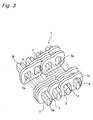
- Fig. 3 shows a power transmission chain 1 (as will also be shortly referred to as the "chain") to be used in that continuously variable transmission system C.
- This continuously variable transmission system C is mounted on an automobile, for example, and is equipped with an input pulley 10 made of a metal (e.g., structural steel) as a first pulley, an output pulley 20 made of a metal (e.g., structural steel) as a second pulley, and the aforementioned power transmission chain 1 looped between the input pulley 10 and the output pulley 20.
- an input pulley 10 made of a metal (e.g., structural steel) as a first pulley
- an output pulley 20 made of a metal (e.g., structural steel) as a second pulley
- the aforementioned power transmission chain 1 looped between the input pulley 10 and the output pulley 20.
- the input pulley 10 is so mounted on an input shaft 11 connected to the engine side as to rotate integrally therewith, and is equipped with a stationary sheave 12 having a conical sheave face 12a and a moving sheave 13 having a conical sheave face 13a arranged to confront the sheave face 12a.
- These sheave faces 12a and 13a form a V-shaped groove, by which the chain 1 is clamped and held by a strong pressure.
- the hydraulic actuator (although not shown) for changing the groove width.
- the moving sheave 13 is moved to vary the groove width so that the chain 1 can be moved to vary the winding radius of the chain 1 relative to the input shaft 11.
- the output pulley 20 is so mounted on an output shaft 21 connected to the drive wheel side as to rotate integrally therewith, and is equipped, like the input pulley 10, with a stationary sheave 23 and a moving sheave 22 having sheave faces for forming a groove to clamp the chain 1 by a strong pressure.
- the hydraulic actuator (although not shown).
- the moving sheave 13 is moved in its axial direction to vary the groove width so that the chain 1 can be moved to vary the winding radius of the chain 1 relative to the output shaft 21.
- the continuously variable transmission system C thus constructed according to this mode of embodiment can change the speed continuously in the following manner. Specifically, in case the rotating speed of the output shaft 21 is to be decelerated, the groove width on the side of the input pulley 10 is enlarged by the movement of the moving sheave 13 to reduce the winding diameter of the chain 1 on the input shaft 11 while the pin end faces 3a and 3b of the chain 1 being held in sliding contact under a boundary lubricating condition toward the inner sides of the conical sheave faces 12a and 13a.
- the groove width is reduced by the movement of the moving sheave 22 to enlarge the winding diameter of the chain 1 on the output shaft 21 while the pin end faces 3a and 3b of the chain 1 being held in sliding contact under a boundary lubricating condition toward the outer sides of conical sheave faces 22a and 23a.
- the rotation of the output shaft 21 can be decelerated.
- the groove width on the side of the input pulley 10 is reduced by the movement of the moving sheave 13 to enlarge the winding diameter of the chain 1 on the input shaft 11 while the pin end faces 3a and 3b of the chain 1 being held in sliding contact under a boundary lubricating condition toward the outer sides of the conical sheave faces 12a and 13a.
- the groove width is enlarged by the movement of the moving sheave 22 to reduce the winding diameter of the chain 1 on the output shaft 21 while the pin end faces 3a and 3b of the chain 1 being held in sliding contact under a boundary lubricating condition toward the inner sides of conical sheave faces 22a and 23a.
- the rotation of the output shaft 21 can be accelerated.
- This chain 1 is constructed to include: a plurality of link plates 2 made of a metal (e.g., carbon steel) and acting as chain constructing members; a plurality of pins 3 made of a metal (e.g., bearing steel) and acting as first or second pin members for connecting those link plates 2 to each other; and strips 4 acting as first or second pin members slightly shorter than those pins 3.
- a plurality of link plates 2 made of a metal (e.g., carbon steel) and acting as chain constructing members
- a plurality of pins 3 made of a metal (e.g., bearing steel) and acting as first or second pin members for connecting those link plates 2 to each other
- the illustration of the widthwise center portion of the chain 1 is partially omitted from Fig. 1.
- the link plates 2 are shaped to have a substantially identical gentle contour, and are individually provided with two through holes 2a.
- Each through hole 2a is shaped to combine two elliptical shapes, which are elongated in a direction perpendicular to the chain advancing direction.
- the pins 3 connecting those link plates 2 are rod members having side faces along the inner peripheries of the through holes 2a, and are all formed to have a substantially identical shape.
- the pin end faces 3a and 3b are formed into protruding curved faces set to have a predetermined curvature so that they contact with the two pulleys to transmit the power.
- the strips 4 are made slightly shorter than the pins, and are rod members which have side faces along the inner peripheries of the through holes 2a and which are all formed to have a substantially identical shape. Moreover, the plural link plates 2 are arranged in an overlapped manner, and are connected to each other in a bendable manner by inserting the pins 3 and the strips 4 into the through holes 2a of the link plates 2 arranged to overlap each other.
- the pin 3 and the strip 4 are so inserted into one through hole 2a that one of them is press-fitted in the through hole 2a whereas the other is rotatably inserted while making rolling contact with the side face of one. Moreover, the other is press-fitted in the through hole 2a of one link plate 2 overlapping and adjoining to another link plate 2. Moreover, said one is rotatably inserted into the through hole 2a of said another link plate 2. Of the pin 3 and the strip 4, one is press-fitted in the through hole 2a whereas the other is rotatably inserted into the through hole 2a, so that the link plates 2 are connected in the bendable manner to each other.
- the bendable chain 1 is constructed by connecting the overlapped link plates 2 in the bendable manner and by arranging the overlapped link plates 2 in a chain width direction perpendicular to the chain advancing direction.
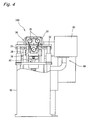
- Fig. 4 shows a preloading apparatus 100 acting as the pretension applying apparatus for applying the pretension to the chain 1p.
- This apparatus 100 is equipped with an apparatus body 30, an hydraulic device 40 positioned on the lower side of the apparatus body 30, a platform 50; and a control device 60 arranged on the side of the apparatus body 30.
- the apparatus body 30 is equipped with: guide posts 31 erected from the two right and left sides of the platform 50; a stationary support plate 32 mounted on the upper ends of the guide posts 31; a stationary portion 33 fixed on the stationary support plate 32; a lifting unit 34 positioned below the stationary portion 33; two upper rollers 35 mounted on the stationary portion 33; and a lower roller 36 mounted on the lifting unit 34.
- the two upper rollers 35 are supported at the same level positions, and the lower roller 36 is so supported at such a lower position as corresponds to the central portion between the two upper rollers 35.
- These upper rollers 35 and lower roller 36 are so arranged that the chain 1p looped between the rollers 35 and 36 forms a triangular shape in a front view.
- the lifting unit 34 In the two right and left sides of the lifting unit 34, moreover, there are individually formed through holes 34a, into which the aforementioned guide posts 31 are inserted, so that the lifting unit 34 can vertically move close to and apart from the stationary portion 33. As a result, the lifting unit 34 is moved upward and downward (i.e., into and out of the aforementioned triangle) by the hydraulic device 40 disposed below the lifting unit 34, so that the distances between the individual upper rollers 35 disposed on the stationary unit 33 and the lower roller 36 carried on the lifting unit 34 vary.
- the central portion of the stationary support plate 32 there is formed an inlet port 32a, into which the upper portion of the lifting unit 34 proceeds as lifting unit 34 rises.
- the upper rollers 35 and the lower roller 36 are individually formed integrally with the leading end of a support shaft 37, as shown in Fig. 6. These support shafts 37 are rotatably supported individually by bearings 38 in the stationary portion 33 and in the lifting unit 34. As a result, the upper rollers 35 and the lower roller 36 are so supported in a cantilever state as can rotate on their individual axes s1 and s2. Moreover, the stationary portion 33 is equipped with the not-shown roller drive units, by which the upper rollers 35 are rotated. At the leading ends of the upper rollers 35 and the lower roller 36, moreover, there are mounted guide caps 39 for mounting the chain 1p easily.
- the control device 60 controls the hydraulic device 40 and the roller drive unit to move the lower roller 36 upward and downward and to rotate the upper rollers 35.
- Each of the upper rollers 35 and the lower roller 36 is equipped with a U-shaped groove u for running the chain 1p. This chain 1p is looped in the individual grooves u of the upper rollers 35 and the lower roller 36.
- a tensile load is applied to the chain 1p.
- the lower roller 36 is lifted together with the lifting unit 34, and the chain 1p is fitted in and looped between the grooves u of the two upper rollers 35 and the lower roller 36. Then, the lower roller 36 is lowered to tense the chain 1p. Next, the upper rollers 35 are rotated, and the lower roller 36 is further lowered by a predetermined distance from the upper rollers 35.
- the chain 1p is loaded with a tensile load while being endlessly turned.
- the chain 1p is endlessly turned by several turns at a peripheral speed for an ordinary use, in which the speed or the rollers take 1,000 rpm.
- the number of turns of the chain 1p is 7 or less, preferably 1.
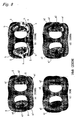
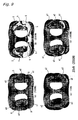
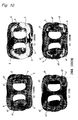
- Fig. 7 to Fig. 10 present the results of the finite element method (FEM) analyses of the stress distributions of the link plates 2 at the time when the pretension was applied to the chain 1p.
- FEM finite element method
- the plastic deformation portions s extend. Especially in Fig. 9 and Fig. 10, the plastic deformation portions s widely extend.
- the compressive stress portion a2 is small in Fig. 7 and Fig. 8, and the compressive stress portion a2 extends wider in Fig. 9 and Fig. 10 in the procedure where the tensile load was applied again.
- the vicinities of the through hole outer corners R are compared at (a) and (d) in the individual Figures.
- (a) shows the time of the pretension
- (d) shows the time of 1,000 (r) when the tension was applied again.
- the variation of the plastic deformation portions s is hardly recognized between (a) and (d) of Fig. 7.
- the plastic deformation portion s exists in Fig. 8(a) between Fig. 8(a) and Fig. 8(d), but the plastic deformation portion is small or hardly exists in Fig. 8(b). Comparing (a) and (d) of Fig. 9 and Fig. 10, it is recognized in (d) of the individual Figures that the plastic deformation portion s become smaller, but that the tensile stress portion h and the compressive stress portions a1 and a2 become larger.
- the plastic deformation portions s are concentrated near the through hole outer corners R, to which the compressive residual stress is applied.
- the plastic deformation portions s are shrunken till the pretension becomes 16 kN.
- the pretension exceeds 20 kN, the tensile stress portions h and the compressive stress portion a2 extend, and it is understood that the pretension is preferably to be set to 12 kN to 16 kN. Therefore, the lower roller 36 is so moved downward from the upper rollers 35 that the pretension may be 12 kN to 16 kN, and the tensile load is applied to the chain 1p while the chain 1p being endlessly turned.
- both the peripheral speed and the peripheral turns of the chain are suppressed so that the plastic deformation does not extend to the portions other than the vicinities of the through hole outer corners R.
- the vicinities of the through hole outer corners R, against which the pins 3 and the strips 4 on the press-fitted and fixed sides abut, are plastically deformed to establish the compressive residual stresses. More specifically, the vicinities, at which the strongest force is applied, of the link plates 2 are especially strengthened to establish the so-called "shake-down state", in which the metallic fatigue is prevented as a result of a rise in the deformation resistance. Moreover, the plastic deformation in the link plates 2 does not extend to the unnecessary portions so that the durability of the chain 1 can be improved.
- the power transmission system C of the mode of embodiment thus far described employs the aforementioned power transmission chain 1 having an improved durability and a stabilized quality so that it can perform the power transmission stably for a long time.
- the power transmission system of the invention should not be limited to the mode, in which the groove widths of both the input pulley and the output pulley fluctuate, but may be exemplified by the mode, in which only one groove width is fluctuated whereas the other is fixed unfluctuant.
- the groove width is continuously fluctuated, but the invention can also be applied to another power transmission system, in which the groove width is stepwise fluctuated or fixed.
- the pin members constituting the chain may also be composed of pin bodies and contact members disposed on the two end portions of the pin bodies.
- the chain may also be of the block type having block members for clamping the overlapped link plates.
Landscapes
- Engineering & Computer Science (AREA)
- General Engineering & Computer Science (AREA)
- Mechanical Engineering (AREA)
- Transmissions By Endless Flexible Members (AREA)
- Devices For Conveying Motion By Means Of Endless Flexible Members (AREA)
- Load-Engaging Elements For Cranes (AREA)
Abstract
Description
- The present invention relates to a power transmission system such as a chain type continuously variable transmission system to be adopted in a vehicle or the like, and to a power transmission chain to be used in the power transmission system.
- A continuously variable transmission (CVT) of an automobile is exemplified to include an input pulley disposed on the engine side, an output pulley disposed on the drive wheel side, and an endless power transmission chain looped between the two pulleys. A known power transmission chain (as referred to
JP-A-8-312725 - In case the power transmission chain of
JP-A-8-312725 - The present invention has been conceived in view of such background, and has an object to provide a power transmission chain having a high durability and a power transmission system using the chain.
- In order to achieve the aforementioned object, the invention takes the following technical means.
- According to the invention, there is provided a power transmission chain comprising:
- a plurality of overlapped link plates, each having a pair of through holes; and
- a plurality of first and second pin members connecting said link plates to each other, of which one is fixed and another other is inserted in a rolling manner into said through holes, said first and second pin members being relatively rotatable in rolling contact with each other,
- According to the invention, the compressive residual stress is applied selectively to the vicinities of those outer corners of the two upper and lower sides of the one pin member, which confront each other in the chain radial direction, so that the plastic deformation does not extend to the unnecessary portion so that the durability of the chain can be improved.
- According to the invention, there is provided a power transmission system comprising a first pulley having a conical sheave face, a second pulley having a conical sheave face, and a power transmission chain looped between said first and second pulleys and contacting with the sheave faces of said first and second pulleys thereby to transmit a power between the two pulleys by a frictional force, characterized in that said power transmission chain is the aforementioned power transmission chain.
- According to the invention, the aforementioned power transmission chain having the high durability is used so that the power transmission can be stably performed for a long time.
- According to the power transmission chain of the invention, the compressive residual stress is applied selectively to the vicinities of those outer corners of the two upper and lower sides of the one pin member, which confront each other in the chain radial direction, so that the plastic deformation does not extend to the unnecessary portion so that the durability of the chain can be improved. Moreover, the power transmission system of the invention uses the aforementioned power transmission chain so that the power transmission can be stably performed for a long time.
-
- Fig. 1 is a perspective view showing the state, in which a power transmission chain is looped between an input pulley and an output pulley.
- Fig. 2 is a sectional view showing an essential construction, in which the power transmission chain is looped on the input pulley.
- Fig. 3 is a perspective view schematically showing an essential construction of the chain.
- Fig. 4 is a front elevation of a three-cylinder type preloading apparatus.
- Fig. 5 is a front elevation of an essential portion of the three-cylinder type preloading apparatus.
- Fig. 6 is a sectional view of the vicinity of an upper lower or a lower roller.
- Fig. 7 shows FEM results of a link plate, to which a preload of 12 kN is applied.
- Fig. 8 shows FEM results of a link plate, to which a preload of 16 kN is applied.
- Fig. 9 shows FEM results of a link plate, to which a preload of 20 kN is applied.
- Fig. 10 shows FEM results of a link plate, to which a preload of 24 kN is applied.
- A mode of embodiment of the invention is described in the following with reference to the accompanying drawings. Fig. 1 and Fig. 2 show a chain type continuously variable transmission system C (as will also be shortly referred to as the "continuously variable transmission system") according to one mode of embodiment of a power transmission system of the invention, and Fig. 3 shows a power transmission chain 1 (as will also be shortly referred to as the "chain") to be used in that continuously variable transmission system C. This continuously variable transmission system C according to this mode of embodiment is mounted on an automobile, for example, and is equipped with an
input pulley 10 made of a metal (e.g., structural steel) as a first pulley, anoutput pulley 20 made of a metal (e.g., structural steel) as a second pulley, and the aforementionedpower transmission chain 1 looped between theinput pulley 10 and theoutput pulley 20. - The
input pulley 10 is so mounted on aninput shaft 11 connected to the engine side as to rotate integrally therewith, and is equipped with astationary sheave 12 having aconical sheave face 12a and a movingsheave 13 having aconical sheave face 13a arranged to confront thesheave face 12a. These sheave faces 12a and 13a form a V-shaped groove, by which thechain 1 is clamped and held by a strong pressure. To the movingsheave 13, on the other hand, there is connected the hydraulic actuator (although not shown) for changing the groove width. At a speed changing time, the movingsheave 13 is moved to vary the groove width so that thechain 1 can be moved to vary the winding radius of thechain 1 relative to theinput shaft 11. - On the other hand, the
output pulley 20 is so mounted on anoutput shaft 21 connected to the drive wheel side as to rotate integrally therewith, and is equipped, like theinput pulley 10, with astationary sheave 23 and a movingsheave 22 having sheave faces for forming a groove to clamp thechain 1 by a strong pressure. To the movingsheave 22 of thispulley 20, like the movingsheave 13 of theinput pulley 10, there is connected the hydraulic actuator (although not shown). At a speed changing time, the movingsheave 13 is moved in its axial direction to vary the groove width so that thechain 1 can be moved to vary the winding radius of thechain 1 relative to theoutput shaft 21. - The continuously variable transmission system C thus constructed according to this mode of embodiment can change the speed continuously in the following manner. Specifically, in case the rotating speed of the
output shaft 21 is to be decelerated, the groove width on the side of theinput pulley 10 is enlarged by the movement of the movingsheave 13 to reduce the winding diameter of thechain 1 on theinput shaft 11 while the pin end faces 3a and 3b of thechain 1 being held in sliding contact under a boundary lubricating condition toward the inner sides of theconical sheave faces output pulley 20, on the other hand, the groove width is reduced by the movement of the movingsheave 22 to enlarge the winding diameter of thechain 1 on theoutput shaft 21 while the pin end faces 3a and 3b of thechain 1 being held in sliding contact under a boundary lubricating condition toward the outer sides of conical sheave faces 22a and 23a. - Thus, the rotation of the
output shaft 21 can be decelerated. In case the rotating speed of theoutput shaft 21 is to be accelerated, on the other hand, the groove width on the side of theinput pulley 10 is reduced by the movement of the movingsheave 13 to enlarge the winding diameter of thechain 1 on theinput shaft 11 while the pin end faces 3a and 3b of thechain 1 being held in sliding contact under a boundary lubricating condition toward the outer sides of theconical sheave faces output pulley 20, on the other hand, the groove width is enlarged by the movement of the movingsheave 22 to reduce the winding diameter of thechain 1 on theoutput shaft 21 while the pin end faces 3a and 3b of thechain 1 being held in sliding contact under a boundary lubricating condition toward the inner sides of conical sheave faces 22a and 23a. Thus, the rotation of theoutput shaft 21 can be accelerated. - The description is made on the
chain 1 to be looped between theinput pulley 10 and theoutput pulley 20. Thischain 1 is constructed to include: a plurality oflink plates 2 made of a metal (e.g., carbon steel) and acting as chain constructing members; a plurality ofpins 3 made of a metal (e.g., bearing steel) and acting as first or second pin members for connecting thoselink plates 2 to each other; andstrips 4 acting as first or second pin members slightly shorter than thosepins 3. Here, the illustration of the widthwise center portion of thechain 1 is partially omitted from Fig. 1. - The
link plates 2 are shaped to have a substantially identical gentle contour, and are individually provided with two throughholes 2a. Each throughhole 2a is shaped to combine two elliptical shapes, which are elongated in a direction perpendicular to the chain advancing direction. Thepins 3 connecting thoselink plates 2 are rod members having side faces along the inner peripheries of the throughholes 2a, and are all formed to have a substantially identical shape. Thepin end faces strips 4 are made slightly shorter than the pins, and are rod members which have side faces along the inner peripheries of the throughholes 2a and which are all formed to have a substantially identical shape. Moreover, theplural link plates 2 are arranged in an overlapped manner, and are connected to each other in a bendable manner by inserting thepins 3 and thestrips 4 into the throughholes 2a of thelink plates 2 arranged to overlap each other. - The
pin 3 and thestrip 4 are so inserted into one throughhole 2a that one of them is press-fitted in the throughhole 2a whereas the other is rotatably inserted while making rolling contact with the side face of one. Moreover, the other is press-fitted in the throughhole 2a of onelink plate 2 overlapping and adjoining to anotherlink plate 2. Moreover, said one is rotatably inserted into the throughhole 2a of said anotherlink plate 2. Of thepin 3 and thestrip 4, one is press-fitted in the throughhole 2a whereas the other is rotatably inserted into the throughhole 2a, so that thelink plates 2 are connected in the bendable manner to each other. Thus, thebendable chain 1 is constructed by connecting the overlappedlink plates 2 in the bendable manner and by arranging the overlappedlink plates 2 in a chain width direction perpendicular to the chain advancing direction. - In order to strengthen the
individual link plates 2 composing thechain 1, the necessary portions of theindividual link plates 2 are plastically deformed to apply the compressive residual stresses. In the manufacturing process, therefore, thepins 3 and thestrips 4 are inserted into the throughholes 2a to connect thelink plates 2 in the bendable manner to each other thereby to obtain anendless loop chain 1p, and thisendless loop chain 1p is pretensed. A pretensing apparatus for applying the pretension is described in the following. - Fig. 4 shows a
preloading apparatus 100 acting as the pretension applying apparatus for applying the pretension to thechain 1p. Thisapparatus 100 is equipped with anapparatus body 30, anhydraulic device 40 positioned on the lower side of theapparatus body 30, aplatform 50; and acontrol device 60 arranged on the side of theapparatus body 30. As shown in Fig. 5, theapparatus body 30 is equipped with: guide posts 31 erected from the two right and left sides of theplatform 50; astationary support plate 32 mounted on the upper ends of the guide posts 31; astationary portion 33 fixed on thestationary support plate 32; alifting unit 34 positioned below thestationary portion 33; twoupper rollers 35 mounted on thestationary portion 33; and alower roller 36 mounted on thelifting unit 34. The twoupper rollers 35 are supported at the same level positions, and thelower roller 36 is so supported at such a lower position as corresponds to the central portion between the twoupper rollers 35. Theseupper rollers 35 andlower roller 36 are so arranged that thechain 1p looped between therollers - In the two right and left sides of the lifting
unit 34, moreover, there are individually formed throughholes 34a, into which the aforementioned guide posts 31 are inserted, so that the liftingunit 34 can vertically move close to and apart from thestationary portion 33. As a result, the liftingunit 34 is moved upward and downward (i.e., into and out of the aforementioned triangle) by thehydraulic device 40 disposed below the liftingunit 34, so that the distances between the individualupper rollers 35 disposed on thestationary unit 33 and thelower roller 36 carried on thelifting unit 34 vary. Here in the central portion of thestationary support plate 32, there is formed aninlet port 32a, into which the upper portion of the liftingunit 34 proceeds as liftingunit 34 rises. - Moreover, the
upper rollers 35 and thelower roller 36 are individually formed integrally with the leading end of asupport shaft 37, as shown in Fig. 6. Thesesupport shafts 37 are rotatably supported individually by bearings 38 in thestationary portion 33 and in thelifting unit 34. As a result, theupper rollers 35 and thelower roller 36 are so supported in a cantilever state as can rotate on their individual axes s1 and s2. Moreover, thestationary portion 33 is equipped with the not-shown roller drive units, by which theupper rollers 35 are rotated. At the leading ends of theupper rollers 35 and thelower roller 36, moreover, there are mounted guide caps 39 for mounting thechain 1p easily. Thecontrol device 60 controls thehydraulic device 40 and the roller drive unit to move thelower roller 36 upward and downward and to rotate theupper rollers 35. Each of theupper rollers 35 and thelower roller 36 is equipped with a U-shaped groove u for running thechain 1p. Thischain 1p is looped in the individual grooves u of theupper rollers 35 and thelower roller 36. When thelower roller 36 is moved downward in this state, a tensile load is applied to thechain 1p. - Here is specifically described a method for pretensing the
chain 1 by using thepreloading apparatus 100 thus far described. At first, thelower roller 36 is lifted together with the liftingunit 34, and thechain 1p is fitted in and looped between the grooves u of the twoupper rollers 35 and thelower roller 36. Then, thelower roller 36 is lowered to tense thechain 1p. Next, theupper rollers 35 are rotated, and thelower roller 36 is further lowered by a predetermined distance from theupper rollers 35. Thechain 1p is loaded with a tensile load while being endlessly turned. Here, thechain 1p is endlessly turned by several turns at a peripheral speed for an ordinary use, in which the speed or the rollers take 1,000 rpm. The number of turns of thechain 1p is 7 or less, preferably 1. - When the turns of the
chain 1p are ended, the rotations of theupper rollers 35 are stopped, and thelower roller 36 is lifted together with the liftingunit 34. Thechain 1 is removed from theindividual rollers preloaded chain 1 is obtained. By this pretension applying method at a slower peripheral speed and at a smaller turning number than those of the prior art, plastic deformations are reliably caused exclusively at those portions in the peripheral edge portions of the throughholes 2a of thelink plate 2, to which a high force is applied from the fixedpins 3 orstrips 4, so that compressive residual stresses are applied to those portions. - Fig. 7 to Fig. 10 present the results of the finite element method (FEM) analyses of the stress distributions of the
link plates 2 at the time when the pretension was applied to thechain 1p. These FEM analyses are obtained in case the tensile load was applied again up to 1,000 N(r) while imaging the practical use, after the individual pretensions of 12 kN, 16 kN, 20 kN and 24 kN were applied and then once released. Here, the maximum tensile load to be applied to the link plates were 1,500 N for a pretension of 12 kN, 2,000 N for 16 kN, 2,500 N for 20 kN, and 3,000 N for 24kN. In the following the description is made as 1,500 N(r), in case the tensile load of 1,500 N was applied to the link plates. In the individual Figures: (a) shows the time of 1, 000 N(r) in the procedure where a specified pretension was applied; (b) shows the time when the specified pretension was applied; (c) shows the time of 10 N(r) when the tensile load was applied again; and (d) shows the time of 1,000 N(r). - From (a) and (b) of the individual Figures, it is understood that a high force by the pretension is applied in the peripheral edges of the through holes having the pin members (e.g., the
pins 3 or the strips 4) fixed, and in the vicinity of the outer corners R of the through holes on the two upper and lower sides confronting in the chain radial direction of one pin member (e.g., thepin 3 or the strip 4). In the Figures: the plastically deformed portions are designated by s; the tensile stress portions by h; the portions of the higher and lower stress values in the compressive stress portions by a1 and a2. As seen from (b) of the individual Figures, the plastic stress portions s are especially concentrated near the through hole outer corners R. As the pretension becomes higher 12 kN, 16 kN, - - -, and so on, the plastic deformation portions s extend. Especially in Fig. 9 and Fig. 10, the plastic deformation portions s widely extend. In view of (c) of the individual Figures, at the time of 10 N(r) when the tensile load was applied again, the compressive stress portion a2 is small in Fig. 7 and Fig. 8, and the compressive stress portion a2 extends wider in Fig. 9 and Fig. 10 in the procedure where the tensile load was applied again. - The vicinities of the through hole outer corners R are compared at (a) and (d) in the individual Figures. As described above, (a) shows the time of the pretension, and (d) shows the time of 1,000 (r) when the tension was applied again. The variation of the plastic deformation portions s is hardly recognized between (a) and (d) of Fig. 7. The plastic deformation portion s exists in Fig. 8(a) between Fig. 8(a) and Fig. 8(d), but the plastic deformation portion is small or hardly exists in Fig. 8(b). Comparing (a) and (d) of Fig. 9 and Fig. 10, it is recognized in (d) of the individual Figures that the plastic deformation portion s become smaller, but that the tensile stress portion h and the compressive stress portions a1 and a2 become larger.
- From the aforementioned analytical results, the plastic deformation portions s are concentrated near the through hole outer corners R, to which the compressive residual stress is applied. At the repeated tension loading time supposing the practical use, the plastic deformation portions s are shrunken till the pretension becomes 16 kN. When the pretension exceeds 20 kN, the tensile stress portions h and the compressive stress portion a2 extend, and it is understood that the pretension is preferably to be set to 12 kN to 16 kN. Therefore, the
lower roller 36 is so moved downward from theupper rollers 35 that the pretension may be 12 kN to 16 kN, and the tensile load is applied to thechain 1p while thechain 1p being endlessly turned. Moreover, both the peripheral speed and the peripheral turns of the chain are suppressed so that the plastic deformation does not extend to the portions other than the vicinities of the through hole outer corners R. - According to the
chain 1 of the mode of embodiment thus far described, the vicinities of the through hole outer corners R, against which thepins 3 and thestrips 4 on the press-fitted and fixed sides abut, are plastically deformed to establish the compressive residual stresses. More specifically, the vicinities, at which the strongest force is applied, of thelink plates 2 are especially strengthened to establish the so-called "shake-down state", in which the metallic fatigue is prevented as a result of a rise in the deformation resistance. Moreover, the plastic deformation in thelink plates 2 does not extend to the unnecessary portions so that the durability of thechain 1 can be improved. - Moreover, the power transmission system C of the mode of embodiment thus far described employs the aforementioned
power transmission chain 1 having an improved durability and a stabilized quality so that it can perform the power transmission stably for a long time. Here, the power transmission system of the invention should not be limited to the mode, in which the groove widths of both the input pulley and the output pulley fluctuate, but may be exemplified by the mode, in which only one groove width is fluctuated whereas the other is fixed unfluctuant. In the foregoing mode, the groove width is continuously fluctuated, but the invention can also be applied to another power transmission system, in which the groove width is stepwise fluctuated or fixed. Moreover, the pin members constituting the chain may also be composed of pin bodies and contact members disposed on the two end portions of the pin bodies. The chain may also be of the block type having block members for clamping the overlapped link plates.
Claims (3)
- A power transmission chain comprising:a plurality of overlapped link plates, each having a pair of through holes; anda plurality of first and second pin members connecting said link plates to each other, of which one is fixed and another other is inserted in a rolling manner into said through holes, said first and second pin members being relatively rotatable in rolling contact with each other,wherein a compressive residual stress is applied selectively to vicinities of outer corners of two upper and lower sides of said one pin member, which confront each other in a chain radial direction.
- The power transmission chain according to claim 1, wherein a pair of the first and second pin members are inserted into one through hole such that the first pin is press-fitted in said through hole and the second pin is rotatably inserted with rolling contact with a side face of said first pin.
- A power transmission system comprising:a first pulley having a conical sheave face, a second pulley having a conical sheave face, and a power transmission chain looped between said first and second pulleys and contacting with the sheave faces of said first and second pulleys thereby to transmit a power between the two pulleys by a frictional force,wherein said power transmission chain is one according to claim 1.
Applications Claiming Priority (1)
| Application Number | Priority Date | Filing Date | Title |
|---|---|---|---|
| JP2006096597A JP2007270942A (en) | 2006-03-31 | 2006-03-31 | Power transmission chain and power transmission device |
Publications (2)
| Publication Number | Publication Date |
|---|---|
| EP1840409A2 true EP1840409A2 (en) | 2007-10-03 |
| EP1840409A3 EP1840409A3 (en) | 2009-12-09 |
Family
ID=38222515
Family Applications (1)
| Application Number | Title | Priority Date | Filing Date |
|---|---|---|---|
| EP07006607A Withdrawn EP1840409A3 (en) | 2006-03-31 | 2007-03-29 | Power transmission chain, and power transmission system |
Country Status (3)
| Country | Link |
|---|---|
| US (1) | US20070232431A1 (en) |
| EP (1) | EP1840409A3 (en) |
| JP (1) | JP2007270942A (en) |
Cited By (2)
| Publication number | Priority date | Publication date | Assignee | Title |
|---|---|---|---|---|
| EP1938916A1 (en) * | 2006-12-01 | 2008-07-02 | JTEKT Corporation | Stress applying method for power transmission chain and stress applying apparatus used in said method |
| NL1034882C2 (en) * | 2008-01-02 | 2009-07-06 | Gear Chain Ind Bv | Device for stretching a transmission chain. |
Families Citing this family (5)
| Publication number | Priority date | Publication date | Assignee | Title |
|---|---|---|---|---|
| JP4803423B2 (en) * | 2005-10-14 | 2011-10-26 | 株式会社ジェイテクト | Power transmission chain and power transmission device including the same |
| WO2008053773A1 (en) * | 2006-10-31 | 2008-05-08 | Jtekt Corporation | Method and device for producing member to be wound, device for measuring circumferential length of member to be wound, and device for applying pretension |
| JP6256756B2 (en) * | 2014-02-12 | 2018-01-10 | 株式会社ジェイテクト | Manufacturing method of power transmission chain |
| JP6298736B2 (en) * | 2014-08-08 | 2018-03-20 | 株式会社豊田中央研究所 | Continuously variable transmission and method for designing continuously variable transmission |
| CN115003929A (en) * | 2020-02-19 | 2022-09-02 | 舍弗勒技术股份两合公司 | Rocker pins for rocker pin pairs of plate link chains |
Citations (1)
| Publication number | Priority date | Publication date | Assignee | Title |
|---|---|---|---|---|
| JPH08312725A (en) | 1995-05-03 | 1996-11-26 | Gear Chain Ind Bv | Transmission chain for cone pulley transmission |
Family Cites Families (8)
| Publication number | Priority date | Publication date | Assignee | Title |
|---|---|---|---|---|
| US4430067A (en) * | 1981-04-20 | 1984-02-07 | Whitaker Ranald O | Variable speed drive with no slippage between belt and sheaves |
| US4507106A (en) * | 1982-11-17 | 1985-03-26 | Borg-Warner Corporation | Power transmission chain |
| DE3664669D1 (en) * | 1985-02-12 | 1989-08-31 | Tsubakimoto Chain Co | Frictional transmission chain |
| JP3076023B1 (en) * | 1999-03-03 | 2000-08-14 | 株式会社椿本チエイン | Low wear elongation silent chain |
| DE10047979B4 (en) * | 1999-10-13 | 2013-05-16 | Schaeffler Technologies AG & Co. KG | Chain |
| EP1698801A4 (en) * | 2003-11-10 | 2009-10-21 | Jtekt Corp | Power transmission chain, power transmission device, and method of producing the chain |
| JP2005291322A (en) * | 2004-03-31 | 2005-10-20 | Koyo Seiko Co Ltd | Power transmission chain and power transmission device equipped with it |
| JP2007051711A (en) * | 2005-08-18 | 2007-03-01 | Jtekt Corp | Power transmission chain and power transmission device including the same |
-
2006
- 2006-03-31 JP JP2006096597A patent/JP2007270942A/en not_active Withdrawn
-
2007
- 2007-03-28 US US11/727,847 patent/US20070232431A1/en not_active Abandoned
- 2007-03-29 EP EP07006607A patent/EP1840409A3/en not_active Withdrawn
Patent Citations (1)
| Publication number | Priority date | Publication date | Assignee | Title |
|---|---|---|---|---|
| JPH08312725A (en) | 1995-05-03 | 1996-11-26 | Gear Chain Ind Bv | Transmission chain for cone pulley transmission |
Cited By (3)
| Publication number | Priority date | Publication date | Assignee | Title |
|---|---|---|---|---|
| EP1938916A1 (en) * | 2006-12-01 | 2008-07-02 | JTEKT Corporation | Stress applying method for power transmission chain and stress applying apparatus used in said method |
| NL1034882C2 (en) * | 2008-01-02 | 2009-07-06 | Gear Chain Ind Bv | Device for stretching a transmission chain. |
| EP2077169A1 (en) * | 2008-01-02 | 2009-07-08 | Gear Chain Industrial B.V. | A device for stretching a transmission chain |
Also Published As
| Publication number | Publication date |
|---|---|
| JP2007270942A (en) | 2007-10-18 |
| EP1840409A3 (en) | 2009-12-09 |
| US20070232431A1 (en) | 2007-10-04 |
Similar Documents
| Publication | Publication Date | Title |
|---|---|---|
| US20070232431A1 (en) | Power transmission chain, and power transmission system | |
| EP1949986B1 (en) | Method of manufacturing a power transmission chain and pretension load device used therein | |
| EP1837552A2 (en) | Power transmission chain and power transmission system | |
| EP1818568A2 (en) | Method of pretensioning power transmission chain, device for said method and power transmission apparatus | |
| JP5347290B2 (en) | Power transmission chain pretension method | |
| EP2249060B1 (en) | Power transmission chain and power transmission device provided therewith | |
| EP1998077A2 (en) | Power transmitting chain and power transmitting apparatus having the same | |
| US8141402B2 (en) | Pretension loading method for power transmission chain and pretension loading apparatus | |
| JP4910982B2 (en) | Manufacturing method of power transmission chain | |
| EP1953413B1 (en) | Power transmission chain and power transmission apparatus | |
| EP1867893A2 (en) | Power transmission chain, and power transmission device having the same | |
| EP1938916B1 (en) | Stress applying method for power transmission chain and stress applying apparatus used in said method | |
| JP4770454B2 (en) | Method for manufacturing power transmission chain for continuously variable transmission | |
| JP4853017B2 (en) | Power transmission chain, method of manufacturing the same, and power transmission device | |
| JP5151140B2 (en) | Power transmission chain and power transmission device | |
| JP4830707B2 (en) | Power transmission chain and power transmission device | |
| JP2011200874A (en) | Method for manufacturing power transmission chain | |
| JP2009028737A (en) | Power transmission chain pretension method and pretension device | |
| JP2008168301A (en) | Power transmission chain manufacturing method and manufacturing apparatus | |
| JP2008215522A (en) | Power transmission chain and power transmission device | |
| JP2009255121A (en) | Pre-tensioning method and apparatus for power transmission chain | |
| JP2009257487A (en) | Power transmission chain and power transmission device | |
| JP2008208980A (en) | Power transmission chain and power transmission device | |
| JP2009115193A (en) | Power transmission chain and power transmission device | |
| JP2009097703A (en) | Power transmission chain and power transmission device |
Legal Events
| Date | Code | Title | Description |
|---|---|---|---|
| PUAI | Public reference made under article 153(3) epc to a published international application that has entered the european phase |
Free format text: ORIGINAL CODE: 0009012 |
|
| AK | Designated contracting states |
Kind code of ref document: A2 Designated state(s): AT BE BG CH CY CZ DE DK EE ES FI FR GB GR HU IE IS IT LI LT LU LV MC MT NL PL PT RO SE SI SK TR |
|
| AX | Request for extension of the european patent |
Extension state: AL BA HR MK YU |
|
| PUAL | Search report despatched |
Free format text: ORIGINAL CODE: 0009013 |
|
| AK | Designated contracting states |
Kind code of ref document: A3 Designated state(s): AT BE BG CH CY CZ DE DK EE ES FI FR GB GR HU IE IS IT LI LT LU LV MC MT NL PL PT RO SE SI SK TR |
|
| AX | Request for extension of the european patent |
Extension state: AL BA HR MK RS |
|
| AKY | No designation fees paid | ||
| STAA | Information on the status of an ep patent application or granted ep patent |
Free format text: STATUS: THE APPLICATION IS DEEMED TO BE WITHDRAWN |
|
| 18D | Application deemed to be withdrawn |
Effective date: 20100511 |
|
| REG | Reference to a national code |
Ref country code: DE Ref legal event code: 8566 |