EP1839958A1 - A connector connecting construction, a clamping member and a method of mounting a connector connecting construction - Google Patents
A connector connecting construction, a clamping member and a method of mounting a connector connecting construction Download PDFInfo
- Publication number
- EP1839958A1 EP1839958A1 EP20070005715 EP07005715A EP1839958A1 EP 1839958 A1 EP1839958 A1 EP 1839958A1 EP 20070005715 EP20070005715 EP 20070005715 EP 07005715 A EP07005715 A EP 07005715A EP 1839958 A1 EP1839958 A1 EP 1839958A1
- Authority
- EP
- European Patent Office
- Prior art keywords
- handle
- frame
- side connector
- wire
- connector
- Prior art date
- Legal status (The legal status is an assumption and is not a legal conclusion. Google has not performed a legal analysis and makes no representation as to the accuracy of the status listed.)
- Granted
Links
- 238000010276 construction Methods 0.000 title claims description 16
- 238000000034 method Methods 0.000 title claims description 9
- 239000011521 glass Substances 0.000 claims description 37
- 230000003028 elevating effect Effects 0.000 claims description 35
- 238000005452 bending Methods 0.000 claims description 10
- 230000000717 retained effect Effects 0.000 description 7
- 238000006073 displacement reaction Methods 0.000 description 6
- 230000003014 reinforcing effect Effects 0.000 description 4
- 238000003780 insertion Methods 0.000 description 2
- 230000037431 insertion Effects 0.000 description 2
- 238000013459 approach Methods 0.000 description 1
- 230000001419 dependent effect Effects 0.000 description 1
- 230000000694 effects Effects 0.000 description 1
- 239000000463 material Substances 0.000 description 1
- 229920003002 synthetic resin Polymers 0.000 description 1
- 239000000057 synthetic resin Substances 0.000 description 1
Images



Classifications
-
- H—ELECTRICITY
- H01—ELECTRIC ELEMENTS
- H01R—ELECTRICALLY-CONDUCTIVE CONNECTIONS; STRUCTURAL ASSOCIATIONS OF A PLURALITY OF MUTUALLY-INSULATED ELECTRICAL CONNECTING ELEMENTS; COUPLING DEVICES; CURRENT COLLECTORS
- H01R13/00—Details of coupling devices of the kinds covered by groups H01R12/70 or H01R24/00 - H01R33/00
- H01R13/58—Means for relieving strain on wire connection, e.g. cord grip, for avoiding loosening of connections between wires and terminals within a coupling device terminating a cable
- H01R13/5804—Means for relieving strain on wire connection, e.g. cord grip, for avoiding loosening of connections between wires and terminals within a coupling device terminating a cable comprising a separate cable clamping part
- H01R13/5812—Means for relieving strain on wire connection, e.g. cord grip, for avoiding loosening of connections between wires and terminals within a coupling device terminating a cable comprising a separate cable clamping part the cable clamping being achieved by mounting the separate part on the housing of the coupling device
-
- E—FIXED CONSTRUCTIONS
- E05—LOCKS; KEYS; WINDOW OR DOOR FITTINGS; SAFES
- E05B—LOCKS; ACCESSORIES THEREFOR; HANDCUFFS
- E05B85/00—Details of vehicle locks not provided for in groups E05B77/00 - E05B83/00
- E05B85/10—Handles
-
- E—FIXED CONSTRUCTIONS
- E05—LOCKS; KEYS; WINDOW OR DOOR FITTINGS; SAFES
- E05B—LOCKS; ACCESSORIES THEREFOR; HANDCUFFS
- E05B79/00—Mounting or connecting vehicle locks or parts thereof
- E05B79/02—Mounting of vehicle locks or parts thereof
- E05B79/06—Mounting of handles, e.g. to the wing or to the lock
-
- E—FIXED CONSTRUCTIONS
- E05—LOCKS; KEYS; WINDOW OR DOOR FITTINGS; SAFES
- E05B—LOCKS; ACCESSORIES THEREFOR; HANDCUFFS
- E05B81/00—Power-actuated vehicle locks
- E05B81/54—Electrical circuits
- E05B81/64—Monitoring or sensing, e.g. by using switches or sensors
- E05B81/76—Detection of handle operation; Detection of a user approaching a handle; Electrical switching actions performed by door handles
-
- E—FIXED CONSTRUCTIONS
- E05—LOCKS; KEYS; WINDOW OR DOOR FITTINGS; SAFES
- E05B—LOCKS; ACCESSORIES THEREFOR; HANDCUFFS
- E05B85/00—Details of vehicle locks not provided for in groups E05B77/00 - E05B83/00
- E05B85/10—Handles
- E05B85/14—Handles pivoted about an axis parallel to the wing
- E05B85/16—Handles pivoted about an axis parallel to the wing a longitudinal grip part being pivoted at one end about an axis perpendicular to the longitudinal axis of the grip part
-
- H—ELECTRICITY
- H01—ELECTRIC ELEMENTS
- H01R—ELECTRICALLY-CONDUCTIVE CONNECTIONS; STRUCTURAL ASSOCIATIONS OF A PLURALITY OF MUTUALLY-INSULATED ELECTRICAL CONNECTING ELEMENTS; COUPLING DEVICES; CURRENT COLLECTORS
- H01R13/00—Details of coupling devices of the kinds covered by groups H01R12/70 or H01R24/00 - H01R33/00
- H01R13/58—Means for relieving strain on wire connection, e.g. cord grip, for avoiding loosening of connections between wires and terminals within a coupling device terminating a cable
- H01R13/582—Means for relieving strain on wire connection, e.g. cord grip, for avoiding loosening of connections between wires and terminals within a coupling device terminating a cable the cable being clamped between assembled parts of the housing
- H01R13/5829—Means for relieving strain on wire connection, e.g. cord grip, for avoiding loosening of connections between wires and terminals within a coupling device terminating a cable the cable being clamped between assembled parts of the housing the clamping part being flexibly or hingedly connected to the housing
-
- H—ELECTRICITY
- H01—ELECTRIC ELEMENTS
- H01R—ELECTRICALLY-CONDUCTIVE CONNECTIONS; STRUCTURAL ASSOCIATIONS OF A PLURALITY OF MUTUALLY-INSULATED ELECTRICAL CONNECTING ELEMENTS; COUPLING DEVICES; CURRENT COLLECTORS
- H01R2201/00—Connectors or connections adapted for particular applications
- H01R2201/26—Connectors or connections adapted for particular applications for vehicles
Definitions
- Each handle attaching main body 72 is gate-shaped in side view by being comprised of one or more, preferably a pair of front and/or rear pieces 72A and a beam 72B, and has an engaging hole 73 inside.
- One or more engaging projections 14 substantially corresponding to the engaging holes 73 are provided on or at the fulcrum portion 11 of the door handle 10.
- the handle attaching portions 62 are brought closer to the door handle 10 to at least partly insert one or more frame plates 11A of the fulcrum portion 11 into the slits 74, whereby the frame plates 11A preferably are held between the handle attaching main bodies 72 and the substantially facing walls 75.
- the second embodiment partly differs from the first embodiment in the shape of a clamping member 60A, but is substantially similar to the first embodiment in other points.
- similar or the same parts as the first embodiment are identified by the same reference numerals and are not repeatedly described.
Landscapes
- Lock And Its Accessories (AREA)
- Clamps And Clips (AREA)
- Installation Of Indoor Wiring (AREA)
Abstract
Description
- The present invention relates to a connector connecting construction arranged in or at a door handle and a handle frame and a clamping member for retaining wires drawn out from a frame-side connector. The present invention further relates to a method of mounting a connector connecting construction.
- Various systems for improving convenience in opening and closing automotive doors have been conventionally known. Various electric parts are built in door handles and handle frames in conformity with such systems. For example, in a system disclosed in
Japanese Unexamined Patent Publication No. 2005-82091 - Since the frame-side connector is connected with an end of a wire group extending from the interior of a vehicle while being separated from the door handle, there are cases where the frame-side connector is pulled inside by this wire group, cannot easily move toward the door handle and, therefore, cannot flexibly follow the displacement of the handle-side connector when the door handle is turned. Then, stresses act on the connecting surfaces of both connectors in directions of displacement, which might result in the action of unnecessary stresses on connected parts of terminal fittings in both connectors.
- The present invention was developed in view of the above situation, and an object thereof is to enable a frame-side connector to be smoothly displaced when a door handle is turned.
- This object is solved according to the invention by the features of the independent claims. Preferred embodiments of the invention are subject of the dependent claims.
- According to the invention, there is provided a connector connecting construction, comprising:
- a handle-side connector fixed or to be fixed to a door handle pivotally hinged to a handle frame and displaceable as the door handle is turned or operated,
- a frame-side connector located or to be located (at least partly) in or at the handle frame so as to be connectable with the handle-side connector, and displaceable together with the handle-side connector in its connected state as the door handle is turned, and
- at least one clamping member including at least one wire retaining portion for retaining a wire group drawn out through or at or near an end surface of the frame-side connector and at least one handle attaching portion substantially continuous with the wire retaining portion and attachable to the door handle so as to make a relative position of the wire retaining portion to the door handle substantially invariable.
- As the door handle is turned or operated, the handle-side connector is displaced and the frame-side connector connected with this handle-side connector is displaced together. At this time, the wire group drawn out through the end surface of the frame-side connector is substantially retained by the wire retaining portion of the clamping member, and the handle attaching portion of this clamping member is attached or mounted to the door handle so as to make the relative position of the wire retaining portion to the door handle substantially invariable. Thus, as the door handle is turned or operated, no unnecessary stress acts on the wire retaining portion from the end surface of the frame-side connector. As a result, stresses acting on the connecting surfaces of the two connectors in directions of displacement can be suppressed, thereby guaranteeing the smooth displacements of the two connector during the turning movement of the door handle.
- According to a preferred embodiment of the invention, an elevating surface of a door glass is or is to be located at a side of the frame-side connector substantially opposite to the door handle.
- Preferably, the wire group includes an inclined portion to be arranged oblique to an elevating surface of a door glass in such a manner as to widen a clearance to the elevating surface of the door glass along a direction away from the end surface of the frame-side connector, and
the wire retaining portion preferably includes at least one inclined guiding means for keeping the inclined posture of the inclined portion. - Since the elevating surface of the door glass is located at the side of the frame-side connector substantially opposite to the door handle, the wire group drawn out through the end surface of the frame-side connector may interfere with the door glass. However, the wire retaining portion of the clamping member includes the inclined guiding means, thereby keeping the inclined posture of the inclined portion arranged oblique or inclined or at an angle different from 0° or 180° to the elevating surface of the door glass in such a manner as to widen the clearance to the elevating surface as the wire group extends along the direction away from the end surface of the frame-side connector. Therefore, the interference of the wire group and the door glass can be avoided.
- Further preferably, the end surface of the frame-side connector faces or is to be arranged so as to substantially face the elevating surface of the door glass,
the wire group is bent after being drawing out through or at or near the end surface of the frame-side connector, the inclined portion extending from the bent position, and has an intermediate part thereof bundled at a bundling position by at least one bundling means, and
out of a plurality of wires forming the wire group, the one to be located at an inner side of the bend by the bending operation preferably is set shorter between the end surface of the frame-side connector and the bundling position than a wire to be located at an outer side of the bend. - With the wire group bent, the wire located at the inner side of the bend is bent at the bent portion while bulging outward for length adjustment, which might result in difficulty in being spatially accommodated. However, according to the above, the wire located at the inner side of the bend is set to have a shorter length between the end surface of the frame-side connector and the bundling position than the wire located at the outer side of the bend. Thus, the bulging-out length at the bent portion of the wire located at the inner side of the bend can be set shorter, wherefore the wire group can have a compact configuration at the bent portion.
- Most preferably, the clamping member further comprises a connector attaching portion attachable to the frame-side connector, wherein:
- the wire retaining portion preferably is substantially in the form of a strip extending from the connector attaching portion, and/or
- an extending direction of the wire group is defined by turning the wire retaining portion about the connector attaching portion with the wire group at least partly arranged along a plate surface of the wire retaining portion.
- According to the invention, there is further provided a clamping member used in the case where a handle-side connector fixed to a door handle pivotally hinged to a handle frame is displaced as the door handle is turned, whereby a frame-side connector connected with the handle-side connector and located in the handle frame is displaced together with the handle-side connector, comprising:
- at least one wire retaining portion for retaining a wire group drawn out through an end surface of the frame-side connector, and
- at least one handle attaching portion substantially continuous with the wire retaining portion and attachable to the door handle so as to make a relative position of the wire retaining portion to the door handle substantially invariable.
- According to a preferred embodiment of the invention, an elevating surface of a door glass is or is to be located at a side of the frame-side connector substantially opposite to the door handle.
- Preferably, the wire group includes an inclined portion to be arranged oblique to an elevating surface of a door glass in such a manner as to widen a clearance to the elevating surface of the door glass along a direction away from the end surface of the frame-side connector, and
the wire retaining portion preferably includes at least one inclined guiding means for keeping the inclined posture of the inclined portion. - Further preferably, a connector attaching portion attachable to the frame-side connector is further provided:
- the wire retaining portion preferably is substantially in the form of a strip extending from the connector attaching portion, and/or
- an extending direction of the wire group is defined by turning the wire retaining portion about the connector attaching portion with the wire group at least partly arranged along a plate surface of the wire retaining portion.
- Since the extending direction of the wire group is defined by turning the wire retaining portion about the connector attaching portion with the wire group arranged along the plate surface of the wire retaining portion, the wire group can be easily bent and can be stably kept bent. Further, the wire group is protected by the wire retaining portion and the connector attaching portion.
- According to the invention, there is further provided method of mounting a connector connecting construction, in particular according to the invention or a preferred embodiment thereof, comprising the following steps:
- fixing a handle-side connector to a door handle pivotally hinged to a handle frame so as to be displaceable as the door handle is turned,
- locating a frame-side connector in or at the handle frame so as to be connectable with the handle-side connector, wherein the frame-side connector is displaceable together with the handle-side connector in its connected state as the door handle is turned,
- retaining a wire group drawn out through or at an end surface of the frame-side connector by means of at least one wire retaining portion of at least one clamping member, and
- attaching at least one handle attaching portion substantially continuous with the wire retaining portion to the door handle so as to make a relative position of the wire retaining portion to the door handle substantially invariable.
- According to a preferred embodiment of the invention, the method further comprises a step of:
- arranging an inclined portion of the wire group oblique to an elevating surface of a door glass in such a manner as to widen a clearance to the elevating surface of the door glass along a direction away from the end surface of the frame-side connector,
- Preferably, the method further comprises the steps of:
- arranging the end surface of the frame-side connector so as to substantially face the elevating surface of the door glass,
- bending the wire group after being drawing out through or at the end surface of the frame-side connector, the inclined portion extending from the bent position, and bundling an intermediate part thereof at a bundling position by at least one bundling means, and
- These and other objects, features and advantages of the present invention will become more apparent upon reading of the following detailed description of preferred embodiments and accompanying drawings. It should be understood that even though embodiments are separately described, single features thereof may be combined to additional embodiments.
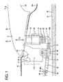
- FIG. 1 is a side view of a connector connecting construction according to a first embodiment,
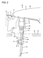
- FIG. 2 is a side view showing a state before a wire group and a clamping member are bent,
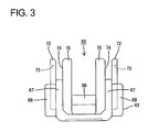
- FIG. 3 is a rear view of the clamping member,
- FIG. 4 is a plan view of the clamping member,
- FIG. 5 is a side view of the clamping member,
- FIG. 6 is a side view of a connector connecting construction according to a second embodiment,
- FIG. 7 is a rear view of a clamping member,
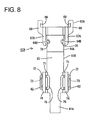
- FIG. 8 is a plan view of the clamping member, and
- FIG. 9 is a side view of the clamping member.
- A first preferred embodiment of the present invention is described with reference to FIGS. 1 to 5. This embodiment illustrates a connector connecting construction in a vehicle door handle device S and a clamping
member 60 used therein. The door handle device S is for building a so-called smart door-lock system applied upon locking and unlocking a door lock and includes adoor handle 10 and ahandle frame 20, wherein a handle-side connector 30 is provided at least partly in or at thedoor handle 10 and a frame-side connector 40 is provided at least partly in or at thehandle frame 20. - As shown in FIG. 1, the
door handle 10 at least partly projects on the outer surface of a door panel 15 (door outer plate) and is comprised of an arm-shapedfulcrum portion 11 and a (preferably substantially hollow and/or flat) handlemain body 12 extending laterally (or backward of a vehicle) from the outer edge of thefulcrum portion 11. The inner surface of the handlemain body 12 is formed into acurved surface 12A separated from aconcave surface 15A of thedoor panel 15, thereby being substantially grip-shaped so as to be easily gripped. Various electric parts (not shown) such as a sensor are built in or provided at the handlemain body 12. The handle-side connector 30 electrically connected with the sensor and the like is integrally or unitarily supported adjacent to thefulcrum portion 11 at a position of the handlemain body 12 near thefulcrum portion 11. This handle-side connector 30 integrally moves with thedoor handle 10. - The
fulcrum portion 11 is at least partly inserted together with the handle-side connector 30 through ahandle insertion opening 16 formed in thedoor panel 15 to be located at least partly inside thedoor panel 15. Ahandle frame 20 to be secured to the inner surface of thedoor panel 15 is prepared inside thedoor panel 15, and thefulcrum portion 11 and the handle-side connector 30 located at least partly inside thedoor panel 15 are introduced into thehandle frame 20. Thefulcrum portion 11 includes ashaft 13, which is engaged or engageable with a bearing portion (not shown) of thehandle frame 20 to permit thedoor handle 10 to turn or pivot about theshaft 13 relative to thehandle frame 20. More specifically, the handlemain body 12 is inclined in an inclination direction ID (arrow of FIG. 1) about theshaft 13 by pulling the rear part of the handlemain body 12 with respect to the vehicle in a direction away from thedoor panel 15. - Further, the frame-
side connector 40 is pivotally arranged in or at thehandle frame 20. The frame-side connector 40 is arranged such that the connecting surface thereof is substantially faced toward thedoor handle 10 substantially in conformity with the arranged position of the handle-side connector 30 when the twoconnectors surface 91 of adoor glass 90 is arranged in proximity to thehandle frame 20 at the inner side of thehandle frame 20, i.e. at a side of thehandle frame 20 substantially opposite to thedoor handle 10. The elevatingsurface 91 of thedoor glass 90 is located at a position substantially behind the connected frame-side connector 40 with respect to a connecting direction CD and/or proximate to the frame-side connector 40. One or more, preferably a plurality of terminal fittings (not shown) are at least partly accommodated in the frame-side connector 40, and the one or more respective terminal fittings are connected with an end of a wire group 80 (one or more, preferably a plurality of (two in the shown case) wires 81) fixed or mounted to a door body and extending substantially from the door body. The respective terminal fittings are further connected with one or more electric signal lines inside the vehicle via thewire group 80. - The clamping
member 60 is engaged with thewire group 80 drawn out through the end surface of the frame-side connector 40. The clampingmember 60 includes awire retaining portion 61 integrally or unitarily formed of a synthetic resin material and adapted to retain thewire group 80, and ahandle attaching portion 62 substantially continuous with thiswire retaining portion 61 and attachable to thedoor handle 10 with thewire group 80 retained by the wire retaining 61. The clampingmember 60 further includes aconnector attaching portion 63 substantially continuous with thewire retaining portion 61 and/or attachable to the frame-side connector 40. - As shown in FIG. 5, the
wire retaining portion 61 preferably is substantially band- or strip-shaped, and one (upper surface shown in FIG. 5) of the substantially opposite plate surfaces thereof serves as a placingsurface 61A for thewire group 80. At a position of thewire retaining portion 61 near one end (position near the connector attaching portion 63) is provided ahinge portion 64, which preferably is thinner than areas of thewire retaining portion 61 before and/or after thehinge portion 64. If thewire retaining portion 61 is turned about theconnector attaching portion 63 in a turning direction TD (arrow shown in FIG. 2) from a state where thewire group 80 is placed on the placingsurface 61A, thehinge portion 64 is resiliently deformed substantially into an arcuate shape and thewire group 80 is forcibly bent near the end surface of the frame-side connector 40. - The
wire retaining portion 61 preferably extends in one direction from a connected part thereof to theconnector attaching portion 63 before being bent, and is provided at a rear portion (preferably substantially at a rear half) thereof with respect to an extending direction with abase plate portion 65 including thehinge portion 64 and/or to be arranged substantially in parallel with the elevatingsurface 91 of thedoor glass 90, and at a front portion (preferably substantially at a front half) thereof with respect to the extending direction with an inclined guidingportion 66 sloped upward toward the leading end. The inclined guidingportion 66 is substantially continuous with thebase plate portion 65 preferably via a step or bent portion so as to be slightly higher than thebase plate portion 65, and/or the width thereof in transverse direction preferably is narrower than that of thebase plate portion 65. Thewire group 80 retained by thewire retaining portion 61 is caused to extend in such a direction as to gradually widen a clearance to the elevatingsurface 91 of thedoor glass 91 by the inclined guidingportion 66. Here, aninclined portion 80A of a preferred embodiment of the present invention is formed. In other words, after extending toward the elevatingsurface 91 of thedoor glass 90 from the end surface of the frame-side connector 40, thewire group 80 becomes aninclined portion 80A via abent portion 80B. Theinclined portion 80A can be held inclined in a substantially constant posture by being supported by the inclined guidingportion 66. - As shown in FIGS. 3 and 4, the
connector attaching portion 63 includes one or more, preferably a pair of lateral (left and/or right) draw-out guiding plates 67 (preferably substantially opposed to each other) and standing up from the (preferably substantially opposite) side edge(s) of a rear end of thewire retaining portion 61 with respect to the extending direction, and one or more connector attachingmain bodies 68 preferably joined on the outer surfaces of the draw-outguiding plates 67. As shown in FIG. 5, the draw-out guiding plate(s) 67 preferably has/have a substantially quarter circular shape in side view by each having anarcuate edge 67A substantially corresponding to the shape of thebent hinge portion 64 of thewire retaining portion 61, and thearcuate edge 67A is arranged substantially along the corresponding side edge of thebent hinge portion 64 of thewire retaining portion 61. The draw-outguiding plates 67 preferably restrict loose movements of thewire group 80 along width direction by being located at the lateral side(s) (preferably at the substantially opposite outer sides) of thewire group 80 retained by thewire retaining portion 61. - The connector attaching
main bodies 68 preferably have a larger thickness than the draw-outguiding plates 67 and include one or more parts projecting more backward than the rear ends of the draw-outguiding plates 67 with respect to the extending direction, and one or more, preferably a pair of lateral (left and/or right) mountinggrooves 69 extending substantially along the rear end(s) of the draw-out guiding plate(s) 67 and making one or more openings in the upper end surface(s) and/or the facing surface(s) of the connector attaching main body/bodies 68 are formed in these backward projecting part(s). The mountinggrooves 69 preferably are in the form of rail grooves substantially transversely symmetrical with respective to the axial line of thewire retaining portion 61. One or moremounting ribs 41 substantially corresponding to the mountinggrooves 69 are provided on an end portion of the frame-side connector 40. By at least partly fitting the end portion of the frame-side connector 40 substantially between the facing surfaces of the connector attachingmain bodies 68, the mountingribs 41 are slid or inserted into the mountinggrooves 69 through the openings made in the upper end surfaces of the connector attachingmain bodies 68 by the mountinggrooves 69. In this way, the clampingmember 60 is detachably attached to the frame-side connector 40. - The
handle attaching portion 62 includes one or more, preferably a pair of lateral (left and/or right) reinforcing plates 71 (preferably substantially opposed to each other) and standing up or projecting from or near the (preferably substantially opposite) side edge(s) of an intermediate part (preferably a substantially middle part) of thewire retaining portion 61 with respect to the extending direction, i.e. a part between thebase plate portion 65 and the inclined guidingportion 66, and one or more handle attachingmain bodies 72 extending upward substantially in parallel with the outer surface(s) of the reinforcing plate(s) 71 after projecting sideways from the outer surface(s) of the reinforcing plate(s) 71. One or more, preferably a pair of lateral (left and/or right) facingwalls 75 preferably extending substantially up to the same position as the extending ends of the handle attachingmain bodies 72 and/or substantially facing the corresponding handle attachingmain bodies 72 while defining one ormore slits 74 are provided on or at the reinforcingplates 71. The facingwalls 75 preferably are located more toward the central axial line of thewire retaining portion 61 than the connector attachingmain bodies 68. - Each handle attaching
main body 72 is gate-shaped in side view by being comprised of one or more, preferably a pair of front and/orrear pieces 72A and abeam 72B, and has an engaginghole 73 inside. One or moreengaging projections 14 substantially corresponding to the engagingholes 73 are provided on or at thefulcrum portion 11 of thedoor handle 10. Thehandle attaching portions 62 are brought closer to thedoor handle 10 to at least partly insert one ormore frame plates 11A of thefulcrum portion 11 into theslits 74, whereby theframe plates 11A preferably are held between the handle attachingmain bodies 72 and the substantially facingwalls 75. When thehandle attaching portions 62 are pushed toward thedoor handle 10, the handle attachingmain bodies 72 resiliently move over the engagingprojections 14 to at least partly fit the engagingprojections 14 into the engagingholes 73, with the result that thehandle attaching portions 62 are attached to thedoor handle 10. In this attached state, the end surfaces of theframe plates 11A rest on the bottom surfaces of theslits 74, thereby preventing thehandle attaching portions 62 from being pushed any further. - Next, an assembling procedure, functions and effects of this embodiment are described.
- First, the handle-
side connector 30 is supported on thedoor handle 10, the handle-side connector 30 and thefulcrum portion 11 are at least partly introduced into thehandle frame 20 through thehandle insertion opening 16 of thedoor handle 10 in this state, and thedoor handle 10 is hinged to thehandle frame 20 via theshaft 13. The frame-side connector 40 connected with the end of thewire group 80 is pivotally located inside thehandle frame 20, and the clampingmember 60 is attached to the frame-side connector 40 laterally (from the right side in FIG. 2) by sliding the mountingribs 41 substantially along the mountinggrooves 69. Thewire group 80 is bundled with the inclined guidingportion 66 by a bundling portion 85 (corresponding to preferred bundling means) preferably by taping or clamping or strip-bundling at an intermediate part thereof. Then, as shown in FIG. 2, the handle-side connector 30 and the frame-side connector 40 are connected to bring the connecting surfaces of both into contact. When the twoconnectors - In the connected state of the two
connectors wire group 80 drawn out through the end surface of the frame-side connector 40 preferably extends substantially straight along thewire retaining portion 61 without being bent at its intermediate position as shown in FIG. 2. At this time, out of thewire group 80, thewire 81A located at an inner side of the bend in the bent state preferably extends substantially straight so as to be at a shortest distance from the end surface of the frame-side connector 40 to a bundling position by the bundlingportion 85, whereas thewire 81B located at an outer side of the bend extends obliquely inward from the end surface of the frame-side connector 40 to the bundling position. In other words, thewires 81A located at the inner side of the bend preferably is shorter between the end surface of the frame-side connector 40 and the bundling position than thewire 81B located at the outer side. - After the two
connectors member 60 and thewire group 80 are united by the bundlingportion 85 via the inclined guidingportion 66, the clampingmember 60 may be turned by holding thewire group 80. Then, thehinge portion 64 is bent about theconnector attaching portion 63 to extend substantially along thearcuate edges 67A of the draw-outguiding plates 67, whereby thehandle attaching portion 62 gradually approaches thefulcrum portion 11 of thedoor handle 10. While the clampingmember 60 is being turned, thewire group 80 comes substantially into contact with the placingsurface 61A of thewire retaining portion 61 to be at least partly placed thereon, and thebent portion 80B is formed as thehinge portion 64 is bent. The inclined posture of theinclined portion 80A is defined by the inclined guidingportion 66, and therespective wires 81 are at least partly supported one above the other on the placingsurface 61A of thewire retaining portion 61. Thewire group 80 preferably is not in contact with the placingsurface 61A of thewire retaining portion 61 between thehinge portion 64 and the inclined guidingportion 66 by the presence of the step or bent portion of the inclined guidingportion 66. - When the
handle attaching portion 62 is turned up to an attached position to thedoor handle 10, the handle attachingmain bodies 72 are resiliently engaged with the engagingprojections 14 as shown in FIG. 1, whereby the clampingmember 60 and thedoor handle 10 are united or integral. In this attached state, theinclined portion 80A of thewire group 80 is supported to substantially extend in such a direction as to widen the clearance to the elevatingsurface 91 of thedoor glass 90 toward the leading end by the inclined guidingportion 66. Thebent portion 80B of thewire 81A located at the inner side of the bend largely bulges out substantially in U-shape as if covering thewire 81B located at the outer side of the bend due to the presence of theinclined portion 80A, but has a compact configuration. - After the clamping
member 60 is attached to thedoor handle 10 in this way, thedoor handle 10 is turned or pivoted in the inclination direction ID (direction of arrow of FIG. 1) about theshaft 13. Then, the handle-side connector 30 is displaced in the rotating direction ID of thedoor handle 10 and the frame-side connector 40 connected with this handle-side connector 30 is likewise displaced in the rotating direction ID of thedoor handle 10, following the displacement of the handle-side connector 30. At this time, thewire group 80 drawn out through the end surface of the frame-side connector 40 is retained by thewire retaining portion 61 of the clampingmember 60, and thehandle attaching portion 62 of the clampingmember 60 is attached and fixed to thedoor handle 10 with thewire group 80 kept retained by thewire retaining portion 61. Thus, even if thedoor handle 10 is turned, the relative position of thewire retaining portion 61 to thedoor handle 10 is fixed. Accordingly, no unnecessary stress acts on the part of thewire group 80 retained by thewire retaining portion 61 from the end surface of the frame-side connector 40 as thedoor handle 10 is turned. As a result, stresses acting on the connecting surfaces (connecting areas) of the twoconnectors connectors door handle 10. - Since the elevating
surface 91 of thedoor glass 90 is located at the side of the frame-side connector 40 opposite to thedoor handle 10, thewire group 80 drawn out through the end surface of the frame-side connector 40 may interfere with thedoor glass 90. However, according to this embodiment, thewire group 80 preferably has the inclinedportion 80A arranged oblique to the elevatingsurface 91 of thedoor glass 90 to widen the clearance to this elevatingsurface 91 along a direction away from the end surface of the frame-side connector 40, and/or the inclined posture of thisinclined portion 80A is stably supported from below by the inclined guidingportion 66 of the clampingmember 60. Therefore, the interference of thewire group 80 and thedoor glass 90 can be avoided. - Further, the
wire 81A to be located at the inner side of the bend by the bending operation is bent at thebent portion 80B while bulging outward for length adjustment because of the presence of theinclined portion 80A, which might result in an excessive bending stress and difficulty in being spatially accommodated. However, according to this embodiment, thewire 81A located at the inner side of the bend preferably is set to have a shorter length between the end surface of the frame-side connector 40 and the bundling position than thewire 81B located at the outer side of the bend. Thus, the bulging-out length at thebent portion 80B of thewire 81A located at the inner side of the bend can be set shorter, wherefore the action of an unnecessarily large bending stress at this position can be prevented and thewire group 80 can have a compact configuration. - Furthermore, since the extending direction of the
wire group 80 can be defined by turning thewire retaining portion 61 about theconnector attaching portion 63 with thewire group 80 arranged substantially along the placingsurface 61A of thewire retaining portion 61, thewire group 80 can be easily bent and stably kept bent. Further, the draw-out end of thewire group 80 can be protected by being at least partly covered by thewire retaining portion 61 and theconnector attaching portion 63. - Accordingly, to enable a frame-side connector to be smoothly displaced, a door handle device S is provided with a handle-
side connector 30 to be fixed to adoor handle 10 to be pivotally hinged to ahandle frame 20 and displaceable as thedoor handle 10 is turned, a frame-side connector 40 located at or at least partly in thehandle frame 20, connectable with the handle-side connector 30 and displaceable together with the handle-side connector 30 in its connected state as thedoor handle 10 is turned or operated, and at least one clampingmember 60 including at least onewire retaining portion 61 for retaining awire group 80 drawn out through or at an end surface of the frame-side connector 40 and ahandle attaching portion 62 substantially continuous with thewire retaining portion 61 and attachable to thedoor handle 10 so as to make a relative position of thewire retaining portion 61 to thedoor handle 10 invariable. - Next, a second preferred embodiment of the present invention is described with reference to FIGS. 6 to 9. The second embodiment partly differs from the first embodiment in the shape of a clamping
member 60A, but is substantially similar to the first embodiment in other points. Thus, similar or the same parts as the first embodiment are identified by the same reference numerals and are not repeatedly described. - A
wire retaining portion 61B is comprised only of abase plate portion 64 having no inclined guidingportion 66 and/or extending substantially straight in one direction from a connected position with aconnector attaching portion 63A before being bent as shown in FIG. 9. Unlike the first embodiment, there is no technical idea of supporting thewire group 80 in an inclined posture in the second embodiment, wherefore there is no likelihood that thebent portion 80B bulges outward and cannot be easily accommodated. A part of thewire retaining portion 61B located before the connected part with thehandle attaching portion 62 is shorter than in the first embodiment, and one ormore ribs 77 extending substantially in width direction for guiding a finger placing movement are formed on the bottom surface of thewire retaining portion 61B opposite to aplacing surface 61A for thewire group 80 while being spaced apart in forward and backward directions. Preferably, there is nothing equivalent to the bundlingportion 85 in the vicinity of the clampingmember 60A, and thehandle attaching portion 62 has the same shape as in the first embodiment. - One or more draw-out
guiding plates 67A of theconnector attaching portions 63A are shorter in forward and backward directions than in the first embodiment because thebent portion 80B of thewire group 80 does not bulge outward, and one or more, preferably a pair of lateral (left and/or right) drop preventingportions 78 project substantially inward at or near the extending ends of the draw-outguiding plates 67A. Thedrop preventing portions 78 preferably are substantially in the form of ribs narrow and long along the extending direction of the draw-outguiding plates 67A, and preferably are transversely symmetrically arranged (preferably at the substantially same height position) on the inner surfaces (substantially facing surfaces) of the draw-outguiding plates 67A. As shown in FIG. 8, one ormore cutouts 64B are made at the (preferably substantially opposite) side edge(s) of ahinge portion 64A by removing molds for thedrop preventing portions 78. - Here, when the
hinge portion 64A is bent as the clampingmember 60A is turned, thedrop preventing portions 78 are brought substantially into contact in width direction with the placingsurface 61A of thewire retaining portion 61B, more specifically an end position of the bending operation by thehinge portion 64A (position near or immediately before thehinge portion 64A). Thus, although thehinge portion 64A preferably has a lower rigidity by being thinned, thehinge portion 64A can be stably held in its bent posture by being supported by thedrop preventing portion 78. - The present invention is not limited to the above described and illustrated embodiments. For example, the following embodiments are also embraced by the technical scope of the present invention as defined by the claims. Beside the following embodiments, various changes can be made without departing from the scope and spirit of the present invention as defined by the claims.
- (1) Although the clamping member is attachable to the frame-side connector by having the connector attaching portion in the foregoing embodiments, it may not be engaged with the frame-side connector without having the connector attaching portion according to the present invention. For example, the clamping member may be comprised of a wire retaining portion for retaining the wire group drawn out through the end surface of the frame-side connector at a position distant from this end surface and a handle attaching portion continuous with this wire retaining portion. In short, it is sufficient for the clamping member to have an invariable relative position to the door handle by having the handle attaching portion.
- (2) Although the bundling portion by taping or the like is provided in addition to the clamping member in the first embodiment, the wire retaining portion may double as the bundling portion according to the present invention. This can reduce the number of parts.
- (3) Although the wire group extends via the bent portion while substantially facing the elevating surface of the door glass in the foregoing embodiments, it may extend without via the bent portion while facing the elevating surface of the door glass. In this case, the facing directions of the connecting surfaces of the two connectors may be set substantially parallel to the elevating surface of the door glass and/or their connecting direction may be substantially normal to the elevating surface of the door glass.
- (4) In the foregoing embodiments, the door handle is provided with the engaging projections and the clamping member is provided with the handle attaching main bodies in the form of projecting pieces. Conversely, according to the present invention, the door handle may be provided with members in the form of projecting pieces equivalent to the handle attaching main bodies and the clamping member may be provided with engaging projections.
- (5) In the foregoing embodiments, the mounting grooves are formed in the connector attaching portion and the mounting ribs are provided on the frame-side connector. Conversely, according to the present invention, the connector attaching portion may be provided with mounting ribs and the frame-side connector may be provided with mounting grooves.
- (6) Although the handle frame is a member separate from the door panel in the foregoing embodiments, it may be constructed as the same member as the door panel according to the present invention.
-
- S ...
- door handle device
- 10 ...
- door handle
- 11 ...
- fulcrum portion
- 13 ...
- shaft
- 20 ...
- handle frame
- 30 ...
- handle-side connector
- 40 ...
- frame-side connector
- 60 ...
- clamping member
- 61 ...
- wire retaining portion
- 62 ...
- handle attaching portion
- 63 ...
- connector attaching portion
- 64 ...
- hinge portion
- 66 ...
- inclined guiding portion (inclined guiding means)
- 80 ...
- wire group
- 80A ...
- inclined portion
- 85 ...
- bundling portion (bundling means)
- 90 ...
- door glass
- 91 ...
- elevating surface
Claims (10)
- A connector connecting construction, comprising:a handle-side connector (30) to be fixed to a door handle (10) pivotally hinged to a handle frame (20) and displaceable as the door handle (10) is turned,a frame-side connector (40) to be located in or at the handle frame (20) so as to be connectable with the handle-side connector (30), and displaceable together with the handle-side connector (30) in its connected state as the door handle (10) is turned, andat least one clamping member (60) including at least one wire retaining portion (61) for retaining a wire group (80) drawn out through or at an end surface of the frame-side connector (40) and at least one handle attaching portion (62) substantially continuous with the wire retaining portion (61) and attachable to the door handle (10) so as to make a relative position of the wire retaining portion (61) to the door handle (10) substantially invariable.
- A connector connecting construction according to claim 1, wherein:the wire group (80) includes an inclined portion (80A) to be arranged oblique to an elevating surface (91) of a door glass (90) in such a manner as to widen a clearance to the elevating surface (91) of the door glass (90) along a direction away from the end surface of the frame-side connector (40), andthe wire retaining portion (61) preferably includes at least one inclined guiding means (66) for keeping the inclined posture of the inclined portion (80A).
- A connector connecting construction according to claim 2, wherein:the end surface of the frame-side connector (40) is to be arranged so as to face the elevating surface (91) of the door glass (90),the wire group (80) is bent after being drawing out through or at the end surface of the frame-side connector (40), the inclined portion (80A) extending from the bent position, and has an intermediate part thereof bundled at a bundling position by at least one bundling means (85), andout of a plurality of wires (81) forming the wire group (80), the one (81A) to be located at an inner side of the bend of the bending operation preferably is set shorter between the end surface of the frame-side connector (40) and the bundling position than a wire (81B) to be located at an outer side of the bend.
- A connector connecting construction according to one or more of the preceding claims, wherein the clamping member (60) further comprises a connector attaching portion (63) attachable to the frame-side connector (40), wherein:the wire retaining portion (61) preferably is substantially in the form of a strip extending from the connector attaching portion (63), and/oran extending direction of the wire group (80) is defined by turning the wire retaining portion (61) about the connector attaching portion (63) with the wire group (80) at least partly arranged along a plate surface of the wire retaining portion (61).
- A clamping member (60) used in the case where a handle-side connector (30) fixed to a door handle (10) pivotally hinged to a handle frame (20) is displaced as the door handle (10) is turned, whereby a frame-side connector (40) connected with the handle-side connector (30) and located in or at the handle frame (20) is displaced together with the handle-side connector (30), comprising:at least one wire retaining portion (61) for retaining a wire group (80) drawn out through or at an end surface of the frame-side connector (40), andat least one handle attaching portion (62) substantially continuous with the wire retaining portion (61) and attachable to the door handle (10) so as to make a relative position of the wire retaining portion (61) to the door handle (10) substantially invariable.
- A clamping member according to claim 5, wherein:the wire group (80) includes an inclined portion (80A) to be arranged oblique to an elevating surface (91) of a door glass (90) in such a manner as to widen a clearance to the elevating surface (91) of the door glass (90) along a direction away from the end surface of the frame-side connector (40), andthe wire retaining portion (61) preferably includes inclined at least one guiding means (66) for keeping the inclined posture of the inclined portion (80A).
- A clamping member according to claim 5 or 6, further comprising a connector attaching portion (63) attachable to the frame-side connector (40), wherein:the wire retaining portion (61) preferably is substantially in the form of a strip extending from the connector attaching portion (63), and/oran extending direction of the wire group (80) is defined by turning the wire retaining portion (61) about the connector attaching portion (63) with the wire group (80) at least partly arranged along a plate surface of the wire retaining portion (61).
- A method of mounting a connector connecting construction, comprising the following steps:fixing a handle-side connector (30) to a door handle (10) pivotally hinged to a handle frame (20) so as to be displaceable as the door handle (10) is turned,locating a frame-side connector (40) in or at the handle frame (20) so as to be connectable with the handle-side connector (30), wherein the frame-side connector (40) is displaceable together with the handle-side connector (30) in its connected state as the door handle (10) is turned,retaining a wire group (80) drawn out through or at an end surface of the frame-side connector (40) by means of at least one wire retaining portion (61) of at least one clamping member (60), andattaching at least one handle attaching portion (62) substantially continuous with the wire retaining portion (61) to the door handle (10) so as to make a relative position of the wire retaining portion (61) to the door handle (10) substantially invariable.
- A method of mounting a connector connecting construction to claim 8, further comprising a step of:arranging an inclined portion (80A) of the wire group (80) oblique to an elevating surface (91) of a door glass (90) in such a manner as to widen a clearance to the elevating surface (91) of the door glass (90) along a direction away from the end surface of the frame-side connector (40),wherein the wire retaining portion (61) preferably includes at least one inclined guiding means (66) for keeping the inclined posture of the inclined portion (80A).
- A method of mounting a connector connecting construction according to claim 9, further comprising the steps of:arranging the end surface of the frame-side connector (40) so as to substantially face the elevating surface (91) of the door glass (90),bending the wire group (80) after being drawing out through or at the end surface of the frame-side connector (40), the inclined portion (80A) extending from the bent position, and bundling an intermediate part thereof at a bundling position by at least one bundling means (85), andout of a plurality of wires (81) forming the wire group (80), the one (81A) to be located at an inner side of the bend of the bending operation preferably is set shorter between the end surface of the frame-side connector (40) and the bundling position than a wire (81B) to be located at an outer side of the bend.
Applications Claiming Priority (1)
| Application Number | Priority Date | Filing Date | Title |
|---|---|---|---|
| JP2006092106A JP4656579B2 (en) | 2006-03-29 | 2006-03-29 | Connector connection structure and clamp member |
Publications (2)
| Publication Number | Publication Date |
|---|---|
| EP1839958A1 true EP1839958A1 (en) | 2007-10-03 |
| EP1839958B1 EP1839958B1 (en) | 2010-12-08 |
Family
ID=38137657
Family Applications (1)
| Application Number | Title | Priority Date | Filing Date |
|---|---|---|---|
| EP20070005715 Ceased EP1839958B1 (en) | 2006-03-29 | 2007-03-20 | A connector connecting construction, a clamping member and a method of mounting a connector connecting construction |
Country Status (6)
| Country | Link |
|---|---|
| US (1) | US7575269B2 (en) |
| EP (1) | EP1839958B1 (en) |
| JP (1) | JP4656579B2 (en) |
| KR (1) | KR100890747B1 (en) |
| CN (1) | CN101067354B (en) |
| DE (1) | DE602007010996D1 (en) |
Cited By (6)
| Publication number | Priority date | Publication date | Assignee | Title |
|---|---|---|---|---|
| EP2525028A3 (en) * | 2011-05-17 | 2014-09-10 | Huf Hülsbeck & Fürst GmbH & Co. KG | Component for a vehicle |
| EP2980343A1 (en) * | 2014-07-30 | 2016-02-03 | Aisin Seiki Kabushiki Kaisha | Door handle apparatus for vehicle |
| WO2020020500A1 (en) * | 2018-07-25 | 2020-01-30 | Huf Hülsbeck & Fürst Gmbh & Co. Kg | Motor vehicle handle |
| FR3110624A1 (en) * | 2020-05-25 | 2021-11-26 | Psa Automobiles Sa | Bracket for opening handle of a motor vehicle sliding door |
| US12385295B2 (en) * | 2021-06-04 | 2025-08-12 | Alpha Corporation | Handle device for vehicle |
| KR102888265B1 (en) * | 2024-12-27 | 2025-11-20 | 주식회사 우보테크 | door latch for vehicle |
Families Citing this family (9)
| Publication number | Priority date | Publication date | Assignee | Title |
|---|---|---|---|---|
| US7458841B2 (en) * | 2006-09-13 | 2008-12-02 | Sumitomo Wiring Systems, Ltd. | Wire cover and a locking construction therefor |
| JP2010216176A (en) * | 2009-03-18 | 2010-09-30 | Aisin Seiki Co Ltd | Door handle device for vehicle |
| CN102177302B (en) | 2009-06-11 | 2013-08-14 | 丰田自动车株式会社 | Electromagnetic coupling device, and door handle and vehicle door both having electromagnetic coupling device |
| JP2014044890A (en) * | 2012-08-28 | 2014-03-13 | Sumitomo Wiring Syst Ltd | Holding structure of optional connector |
| DE102013214947A1 (en) * | 2013-07-31 | 2015-02-05 | Robert Bosch Gmbh | End position fixation of a plug connection to increase the vibration resistance |
| US10145151B2 (en) * | 2015-04-30 | 2018-12-04 | Huf North America Automotive Parts Manufacturing Corp. | Retention mechanism for vehicular door handle assembly |
| RU2733027C2 (en) * | 2016-05-31 | 2020-09-28 | Бомбардье Рекриэйшенел Продактс Инк. | Tethered system for power supply from vehicle to equipment |
| CN107520736A (en) * | 2017-09-29 | 2017-12-29 | 广东利迅达机器人系统股份有限公司 | A kind of door handle polishing wire-drawing equipment |
| JP7147607B2 (en) * | 2019-02-08 | 2022-10-05 | 株式会社オートネットワーク技術研究所 | DOOR WIRING MODULE AND DOOR WIRING MODULE MANUFACTURING METHOD |
Citations (7)
| Publication number | Priority date | Publication date | Assignee | Title |
|---|---|---|---|---|
| GB2183405A (en) * | 1985-11-25 | 1987-06-03 | Plastic Seals Limited | Strain relief bushing for clamping an electrical cable |
| DE3625119A1 (en) * | 1986-07-25 | 1988-01-28 | Audi Ag | Fastening element for flexible, elongate construction elements |
| US6033251A (en) * | 1998-05-26 | 2000-03-07 | Cook; James E. | Extension cord locking device |
| DE19830635C1 (en) * | 1998-07-09 | 2000-04-06 | Eichhoff Gmbh | Mains connector with spark suppression for electrical equipment has lug protruding from suppresser housing with earth connector forming mains cable strain reliever with mounting plate |
| EP1031683A1 (en) * | 1999-02-23 | 2000-08-30 | Valeo Sicurezza Abitacolo S.p.A. | Vehicle door handle |
| FR2816121A1 (en) * | 2000-10-28 | 2002-05-03 | Bosch Gmbh Robert | Tension relief device for electrical cable bundles, uses clamp with cavity in its base and strap that folds over to clamp cable bundle into cavity |
| EP1437461A2 (en) * | 2003-01-11 | 2004-07-14 | Hella KG Hueck & Co. | Method of manufacturing a door locking device for a vehicle and a door locking device manufactured by said method |
Family Cites Families (7)
| Publication number | Priority date | Publication date | Assignee | Title |
|---|---|---|---|---|
| DE19947977C1 (en) * | 1999-10-05 | 2001-05-03 | Huf Huelsbeck & Fuerst Gmbh | Device for actuating an electronic locking system and / or a lock installed in a door, a flap or the like, in particular in a vehicle |
| JP2004162338A (en) * | 2002-11-12 | 2004-06-10 | Aisin Seiki Co Ltd | Vehicle door handle device |
| JP4096707B2 (en) * | 2002-11-14 | 2008-06-04 | アイシン精機株式会社 | Cable routing structure |
| JP3826881B2 (en) | 2002-11-26 | 2006-09-27 | アイシン精機株式会社 | Vehicle door handle device |
| JP4015568B2 (en) | 2003-01-29 | 2007-11-28 | アイシン精機株式会社 | Outside handle device and connector structure thereof |
| US7057124B2 (en) | 2003-04-22 | 2006-06-06 | Aisin Seiki Kabushiki Kaisha | Push switch apparatus |
| JP4501381B2 (en) * | 2003-09-10 | 2010-07-14 | アイシン精機株式会社 | Connector holding structure |
-
2006
- 2006-03-29 JP JP2006092106A patent/JP4656579B2/en not_active Expired - Lifetime
-
2007
- 2007-03-20 DE DE200760010996 patent/DE602007010996D1/en active Active
- 2007-03-20 EP EP20070005715 patent/EP1839958B1/en not_active Ceased
- 2007-03-26 US US11/728,481 patent/US7575269B2/en active Active
- 2007-03-29 KR KR20070030935A patent/KR100890747B1/en not_active Expired - Fee Related
- 2007-03-29 CN CN2007100890639A patent/CN101067354B/en active Active
Patent Citations (7)
| Publication number | Priority date | Publication date | Assignee | Title |
|---|---|---|---|---|
| GB2183405A (en) * | 1985-11-25 | 1987-06-03 | Plastic Seals Limited | Strain relief bushing for clamping an electrical cable |
| DE3625119A1 (en) * | 1986-07-25 | 1988-01-28 | Audi Ag | Fastening element for flexible, elongate construction elements |
| US6033251A (en) * | 1998-05-26 | 2000-03-07 | Cook; James E. | Extension cord locking device |
| DE19830635C1 (en) * | 1998-07-09 | 2000-04-06 | Eichhoff Gmbh | Mains connector with spark suppression for electrical equipment has lug protruding from suppresser housing with earth connector forming mains cable strain reliever with mounting plate |
| EP1031683A1 (en) * | 1999-02-23 | 2000-08-30 | Valeo Sicurezza Abitacolo S.p.A. | Vehicle door handle |
| FR2816121A1 (en) * | 2000-10-28 | 2002-05-03 | Bosch Gmbh Robert | Tension relief device for electrical cable bundles, uses clamp with cavity in its base and strap that folds over to clamp cable bundle into cavity |
| EP1437461A2 (en) * | 2003-01-11 | 2004-07-14 | Hella KG Hueck & Co. | Method of manufacturing a door locking device for a vehicle and a door locking device manufactured by said method |
Cited By (7)
| Publication number | Priority date | Publication date | Assignee | Title |
|---|---|---|---|---|
| EP2525028A3 (en) * | 2011-05-17 | 2014-09-10 | Huf Hülsbeck & Fürst GmbH & Co. KG | Component for a vehicle |
| EP2980343A1 (en) * | 2014-07-30 | 2016-02-03 | Aisin Seiki Kabushiki Kaisha | Door handle apparatus for vehicle |
| US10267072B2 (en) | 2014-07-30 | 2019-04-23 | Aisin Seiki Kabushiki Kaisha | Door handle apparatus for vehicle |
| WO2020020500A1 (en) * | 2018-07-25 | 2020-01-30 | Huf Hülsbeck & Fürst Gmbh & Co. Kg | Motor vehicle handle |
| FR3110624A1 (en) * | 2020-05-25 | 2021-11-26 | Psa Automobiles Sa | Bracket for opening handle of a motor vehicle sliding door |
| US12385295B2 (en) * | 2021-06-04 | 2025-08-12 | Alpha Corporation | Handle device for vehicle |
| KR102888265B1 (en) * | 2024-12-27 | 2025-11-20 | 주식회사 우보테크 | door latch for vehicle |
Also Published As
| Publication number | Publication date |
|---|---|
| CN101067354A (en) | 2007-11-07 |
| KR100890747B1 (en) | 2009-03-26 |
| KR20070098666A (en) | 2007-10-05 |
| JP2007262832A (en) | 2007-10-11 |
| CN101067354B (en) | 2011-04-06 |
| EP1839958B1 (en) | 2010-12-08 |
| US7575269B2 (en) | 2009-08-18 |
| US20070228768A1 (en) | 2007-10-04 |
| DE602007010996D1 (en) | 2011-01-20 |
| JP4656579B2 (en) | 2011-03-23 |
Similar Documents
| Publication | Publication Date | Title |
|---|---|---|
| EP1839958B1 (en) | A connector connecting construction, a clamping member and a method of mounting a connector connecting construction | |
| EP1832791B1 (en) | A fixture | |
| EP1521024A1 (en) | Clamp for slender object such as a cable | |
| EP1944836B1 (en) | Electrical connection box and assembling method of electrical connection box | |
| CN107104326B (en) | Connector with Terminal Position Assurance device | |
| EP1923962A1 (en) | A connector and method of preassembling it | |
| EP2063499A2 (en) | A connector assembly, connector, connector assembling construction and method of assembling them | |
| KR20070051373A (en) | Fastening device for connector element and connector with said device | |
| EP1662628B1 (en) | A mounting fitting | |
| EP1557911B1 (en) | A connector assembling construction and assembling method | |
| EP1926193B1 (en) | A locking construction, connector provided therewith and unlocking method | |
| JP3698250B2 (en) | connector | |
| US20180048092A1 (en) | Connector with connector position assurance | |
| EP1801925B1 (en) | A connector | |
| US7458841B2 (en) | Wire cover and a locking construction therefor | |
| EP0939260A2 (en) | A clamping construction for an automotive wiring harness | |
| JP4295704B2 (en) | Protector | |
| KR101908551B1 (en) | Device for connecting a wiper blade to wiper arms | |
| EP1801926B1 (en) | A connetor and connector assembly | |
| US20040137315A1 (en) | Battery positive cover | |
| EP1710870A1 (en) | A connector assembling construction and method | |
| CN106034399A (en) | Wiper arm | |
| JPH0984240A (en) | Fixed protector | |
| JP4341465B2 (en) | connector | |
| KR102008449B1 (en) | Shield connector |
Legal Events
| Date | Code | Title | Description |
|---|---|---|---|
| PUAI | Public reference made under article 153(3) epc to a published international application that has entered the european phase |
Free format text: ORIGINAL CODE: 0009012 |
|
| 17P | Request for examination filed |
Effective date: 20070329 |
|
| AK | Designated contracting states |
Kind code of ref document: A1 Designated state(s): AT BE BG CH CY CZ DE DK EE ES FI FR GB GR HU IE IS IT LI LT LU LV MC MT NL PL PT RO SE SI SK TR |
|
| AX | Request for extension of the european patent |
Extension state: AL BA HR MK YU |
|
| AKX | Designation fees paid |
Designated state(s): DE FR |
|
| RIN1 | Information on inventor provided before grant (corrected) |
Inventor name: NISHIYAMA, SHIGEKI Inventor name: FUNAYAMA, TOMOYUKI Inventor name: KAKEGAWA, TOMOO Inventor name: KOBAYASHI, TOMOHIKO Inventor name: KOBAYASHI, HIROSHI |
|
| GRAP | Despatch of communication of intention to grant a patent |
Free format text: ORIGINAL CODE: EPIDOSNIGR1 |
|
| GRAS | Grant fee paid |
Free format text: ORIGINAL CODE: EPIDOSNIGR3 |
|
| GRAA | (expected) grant |
Free format text: ORIGINAL CODE: 0009210 |
|
| AK | Designated contracting states |
Kind code of ref document: B1 Designated state(s): DE FR |
|
| REF | Corresponds to: |
Ref document number: 602007010996 Country of ref document: DE Date of ref document: 20110120 Kind code of ref document: P |
|
| PLBE | No opposition filed within time limit |
Free format text: ORIGINAL CODE: 0009261 |
|
| STAA | Information on the status of an ep patent application or granted ep patent |
Free format text: STATUS: NO OPPOSITION FILED WITHIN TIME LIMIT |
|
| 26N | No opposition filed |
Effective date: 20110909 |
|
| REG | Reference to a national code |
Ref country code: DE Ref legal event code: R097 Ref document number: 602007010996 Country of ref document: DE Effective date: 20110909 |
|
| REG | Reference to a national code |
Ref country code: FR Ref legal event code: PLFP Year of fee payment: 10 |
|
| REG | Reference to a national code |
Ref country code: FR Ref legal event code: PLFP Year of fee payment: 11 |
|
| REG | Reference to a national code |
Ref country code: DE Ref legal event code: R084 Ref document number: 602007010996 Country of ref document: DE |
|
| REG | Reference to a national code |
Ref country code: FR Ref legal event code: PLFP Year of fee payment: 12 |
|
| PGFP | Annual fee paid to national office [announced via postgrant information from national office to epo] |
Ref country code: FR Payment date: 20210210 Year of fee payment: 15 |
|
| PGFP | Annual fee paid to national office [announced via postgrant information from national office to epo] |
Ref country code: DE Payment date: 20210310 Year of fee payment: 15 |
|
| REG | Reference to a national code |
Ref country code: DE Ref legal event code: R119 Ref document number: 602007010996 Country of ref document: DE |
|
| PG25 | Lapsed in a contracting state [announced via postgrant information from national office to epo] |
Ref country code: FR Free format text: LAPSE BECAUSE OF NON-PAYMENT OF DUE FEES Effective date: 20220331 Ref country code: DE Free format text: LAPSE BECAUSE OF NON-PAYMENT OF DUE FEES Effective date: 20221001 |