EP1839946B1 - Beleuchtungsvorrichtung für elektrischen Zigarrenanzünder oder multi-funktionelle elektrische Steckdose - Google Patents
Beleuchtungsvorrichtung für elektrischen Zigarrenanzünder oder multi-funktionelle elektrische Steckdose Download PDFInfo
- Publication number
- EP1839946B1 EP1839946B1 EP07290347A EP07290347A EP1839946B1 EP 1839946 B1 EP1839946 B1 EP 1839946B1 EP 07290347 A EP07290347 A EP 07290347A EP 07290347 A EP07290347 A EP 07290347A EP 1839946 B1 EP1839946 B1 EP 1839946B1
- Authority
- EP
- European Patent Office
- Prior art keywords
- light
- piece component
- printed circuit
- intermediate part
- ring
- Prior art date
- Legal status (The legal status is an assumption and is not a legal conclusion. Google has not performed a legal analysis and makes no representation as to the accuracy of the status listed.)
- Active
Links
Images


Classifications
-
- H—ELECTRICITY
- H01—ELECTRIC ELEMENTS
- H01R—ELECTRICALLY-CONDUCTIVE CONNECTIONS; STRUCTURAL ASSOCIATIONS OF A PLURALITY OF MUTUALLY-INSULATED ELECTRICAL CONNECTING ELEMENTS; COUPLING DEVICES; CURRENT COLLECTORS
- H01R13/00—Details of coupling devices of the kinds covered by groups H01R12/70 or H01R24/00 - H01R33/00
- H01R13/66—Structural association with built-in electrical component
- H01R13/6608—Structural association with built-in electrical component with built-in single component
- H01R13/6641—Structural association with built-in electrical component with built-in single component with diode
-
- B—PERFORMING OPERATIONS; TRANSPORTING
- B60—VEHICLES IN GENERAL
- B60Q—ARRANGEMENT OF SIGNALLING OR LIGHTING DEVICES, THE MOUNTING OR SUPPORTING THEREOF OR CIRCUITS THEREFOR, FOR VEHICLES IN GENERAL
- B60Q3/00—Arrangement of lighting devices for vehicle interiors; Lighting devices specially adapted for vehicle interiors
- B60Q3/20—Arrangement of lighting devices for vehicle interiors; Lighting devices specially adapted for vehicle interiors for lighting specific fittings of passenger or driving compartments; mounted on specific fittings of passenger or driving compartments
- B60Q3/275—Smoking-related fittings, e.g. cigarette lighters or ashtrays
-
- H—ELECTRICITY
- H01—ELECTRIC ELEMENTS
- H01R—ELECTRICALLY-CONDUCTIVE CONNECTIONS; STRUCTURAL ASSOCIATIONS OF A PLURALITY OF MUTUALLY-INSULATED ELECTRICAL CONNECTING ELEMENTS; COUPLING DEVICES; CURRENT COLLECTORS
- H01R13/00—Details of coupling devices of the kinds covered by groups H01R12/70 or H01R24/00 - H01R33/00
- H01R13/66—Structural association with built-in electrical component
- H01R13/665—Structural association with built-in electrical component with built-in electronic circuit
- H01R13/6658—Structural association with built-in electrical component with built-in electronic circuit on printed circuit board
-
- H—ELECTRICITY
- H01—ELECTRIC ELEMENTS
- H01R—ELECTRICALLY-CONDUCTIVE CONNECTIONS; STRUCTURAL ASSOCIATIONS OF A PLURALITY OF MUTUALLY-INSULATED ELECTRICAL CONNECTING ELEMENTS; COUPLING DEVICES; CURRENT COLLECTORS
- H01R13/00—Details of coupling devices of the kinds covered by groups H01R12/70 or H01R24/00 - H01R33/00
- H01R13/66—Structural association with built-in electrical component
- H01R13/717—Structural association with built-in electrical component with built-in light source
- H01R13/7172—Conduits for light transmission
-
- H—ELECTRICITY
- H01—ELECTRIC ELEMENTS
- H01R—ELECTRICALLY-CONDUCTIVE CONNECTIONS; STRUCTURAL ASSOCIATIONS OF A PLURALITY OF MUTUALLY-INSULATED ELECTRICAL CONNECTING ELEMENTS; COUPLING DEVICES; CURRENT COLLECTORS
- H01R13/00—Details of coupling devices of the kinds covered by groups H01R12/70 or H01R24/00 - H01R33/00
- H01R13/66—Structural association with built-in electrical component
- H01R13/717—Structural association with built-in electrical component with built-in light source
- H01R13/7175—Light emitting diodes (LEDs)
Definitions
- the present invention relates to electric cigarette lighters, or multifunction electrical sockets, in particular for equipping motor vehicles. It relates more particularly to the means for illuminating cigarette lighters or multi-function plugs, in particular in the form of illuminating rings associated with an illuminating module.
- the cigarette lighters are illuminated by a lamp mounted in a lighting module.
- the power supply of this lamp is achieved through blades of conductive material. These blades are on the one hand in electrical contact with the body of the cigarette lighter mass. They are on the other hand either in contact with a tab of the connector, or directly connected to the power supply cable.
- An example of a lighting module carried by an illuminating ring of a cigarette lighter is described in the patent FR 2,758,111 .
- a first improvement of LED lighting modules has been proposed in the patent EP 1,516,777 : it is an illuminating ring on which is mounted an illuminating module, said illuminating module comprising a printed circuit provided with at least one light-emitting diode, a cover intended to house at least part of the printed circuit, and at least two power supply tabs of said printed circuit, mechanically fixed to said cover.
- the invention therefore aims to further improve the design of lighting modules for cigarette lighter or multi-function socket.
- the invention seeks in particular to develop lighting modules using light-emitting diodes, and which are reliable and long-life, but which are also, for example, more compact and / or easier to mount in an automated manner and / or more reliable as to their electrical connection, and / or more efficient in terms of illumination obtained.
- the printed circuit (s) is (are) deposited on its substrate and provided with all the appropriate conductive tracks and electronic components.
- This printed circuit may also be provided with one or more resistors, capacitors or diodes.
- a multifunction socket especially for a motor vehicle, comprises a hollow body serving socket (which can be compared to the ignition body of a cigarette lighter), which comprises means of electrical connection and which is intended to cooperate with a removable accessory socket (the ignition body of the cigarette lighter cooperating, him, with a removable cap functional, heating).
- the invention therefore uses a single piece, said monoblock component, both to maintain the printed circuit and to act as an illuminating ring. It no longer uses a separate hood as described in EP Patent 1,516,777 , which is industrially very interesting: it can mold this element in one piece, which simplifies and shortens the manufacture of the illuminating module.
- the one-piece component is made of a transparent material based on a polymer, in particular based on polycarbonate, which can be easily injection molded, and which has the required properties in terms of thermal and mechanical resistance.
- the monobloc component can be tinted in different colors.
- the intermediate portion comprises an intermediate portion between the illuminating ring and the housing for the printed circuit, said intermediate portion serving as a light guide for conducting the light emitted by the light-emitting diode to the illuminating ring.
- This "integrated light guide” may in fact be in the form of an extension of the illuminating ring towards the source of light, the light emitting diode, which is adapted to channel this light to the ring as best as possible. Concretely, by forcing the light emitted by the light-emitting diode to progress through this light guide towards the ring, by total reflection of the light rays in this guide, the quantity of light reaching the ring is very significantly increased, and thus light is obtained. cigars significantly more enlightened.
- the light progressed from the light emitting diode to the ring by diffusion of light into the ring and by reflection on the ignition body surrounding the ring, which, optically, favored light leakage.
- the intermediate portion of the one-piece component has a curved profile, with at least one point of inflection, in particular two.
- it may have a profile having at least two inclined faces relative to each other. In both cases, it is best to adapt the shape of this integrated light guide to allow total reflection of the light rays propagated therein, the guide being defined by a profile delimited by two walls.
- the intermediate portion of the monoblock component has an input face for collecting the best light emitted by the emitting surface of the light emitting diode.
- This face serves as a collimator of the light it receives, and its adapted shape may have a toric or cylindrical surface. Any concave surface that best "envelops" the light cone emitted by the light-emitting diode, collimating it, is possible.
- the intermediate portion of the one-piece component is generally at least partially annular in shape, with a preferably flared shape towards the illuminating ring. Compared to a usual lighting module, it has therefore extended and flared the ring towards the bottom of the ignition body, towards the light emitting diode.
- This intermediate part not only acts as a guide light guide, but also ensures the mechanical connection between the ring and the housing of the printed circuit.
- the ring can extend the ring only over a portion of its circumference, to ensure the mechanical and optical connection with the housing of the light-emitting diode printed circuit, which itself can be compared to a leg, an appendage of preferably elongate shape according to an axis parallel to the central axis of the ring (which is also the axis of the ignition body of the cigarette lighter).
- the intermediate portion of the one-piece component has a means for preventing the formation of a hot spot of light in the illuminating ring in line with its entrance light.
- the ring tended to illuminate more strongly the area above the entrance face of the light guide, so just “above” the point of injection of light in the monoblock component. (hot spot area).
- a means is provided for the trajectory of the light rays incriminated is deliberately disturbed.
- the intermediate portion may comprise at least one dedicated zone which guides a portion of the light emitted by the diode and propagating in said intermediate portion towards an exit face, in particular for illuminating an accessory near the ring: the locally adapted form of the intermediate part, thus diverting part of the light emitted by the diode to make it go out locally, to create a light spot, which can be used, for example, to light an ashtray in the case of a cigarette lighter.
- the previously described device is associated with a printed circuit inserted at least partly in the housing provided in the one-piece component, the printed circuit being provided with a diode, and two electrical connection tabs, in particular fixed by welding to said circuit .
- welded tongues are very advantageous to use: they can be of very simple geometrical shape to achieve, in addition, this solid mechanical fastening, by welding, is very reliable, the mechanical contact, and therefore electrical, being safer than in the past. use of connecting tongues coming to rest on the conductive surfaces of the circuit by spring effect.
- the circuit is in particular of the CMS type, that is to say non-through, still called surface printed circuit.
- the diode is preferably chosen of the "side emitter” type, that is to say with lateral emission: one can thus have a printed circuit, which is located substantially in a plane parallel to the axis of the ring and that of the ignition body, and a light-emitting diode which emits laterally, also in a main direction parallel to the central axis of the ring: this configuration facilitates the design of the injection point of the light in the monobloc component, namely the input face previously described, and the light rays thus enter the component with already a direction generally directed towards the ring.
- the printed circuit may also be provided with a second light diode, in particular of the reverse-emission type (known as the reverse gullwing diode).
- second diode can be dedicated to create a light spot able to illuminate a nearby accessory, such as an ashtray. We keep a unique circuit board.
- An equivalent solution, less economic and more cumbersome, is to use two contiguous printed circuits, the first provided with the diode for supplying light to the illuminating ring, the second equipped with another diode for illuminating an accessory type ashtray or other.
- the printed circuit is, for example, inserted into the housing of the one-piece component by means of guiding means provided in the housing, in particular of the sliding type. It is thus possible to provide two parallel slides in the housing cooperating with the two opposite edges of the printed circuit.
- the printed circuit is mechanically locked in the housing of the one-piece component, in particular by means of pins protruding from it and realizing stops preventing it from coming out of the slideway (s), and complementary cavities present in the hood, type clipping system.
- a slight deformation of the circuit advantageously allows it to exceed these stops during assembly.
- the invention also relates to the entire cigarette lighter, comprising the device described above, with an ignition body inserted into the one-piece component. It also relates to the entire multi-function socket, comprising a hollow body acting as a plug inserted in the monoblock component.
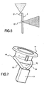
- FIGS. 1 and 2 therefore represent some of the components of a cigarette lighter with illuminating ring.
- a detailed description of a complete cigarette lighter can be found in the patent FR 2,758,111 .
- the description below will focus on the features more specific to the illuminating module according to the invention.
- This cigarette lighter has an ignition body 5 for receiving and heating a removable heating cap not shown. It also comprises a one-piece component 1, entirely molded from a translucent polycarbonate block, in which is inserted in the mounting the ignition body 5. A connector 6 is fixed to the ignition body.
- the ring 11 and / or the intermediate portion 12 are provided with mechanical means such as lugs, stops, cavities, intended to cooperate with means of complementary shape for fixing the component to the ignition body.
- connection tab 4a soldered to the printed circuit 3 is, in the mounting position of the assembly, in contact with the ignition body 5 corresponding to the 0 volts of the vehicle. Furthermore, the other tab 4b soldered to the printed circuit is in contact with the leg of the three-point connector under a voltage of 12 volts.
- a conventional light-emitting diode may be used which emits perpendicular to the printed circuit, in which case the shape of the intermediate portion is to be adapted.
- the figure 4b represents the path of two arbitrary rays, striking the lower edges of the tongue f in opposite oblique directions.
- the path of a third light beam starting from the input face FE much more obliquely is also represented in this figure. It is understood that the multiplicity of radii from the input face allows, by a succession of total reflections, the light of the light emitting diode to reach the entire circumference of the ring.
- the ring with this system of propagation of light, illuminates significantly more. To give an order of magnitude, it illuminates at least twice as much as with the illuminating module described in the aforementioned patent EP 1,516,777 , for a light-emitting diode emitting the same luminous flux.
- the figure 5 details the printed circuit board 3 and its main components. It is fixed to the housing 13 of the one-piece component by a system of slides present in the housing and in which the circuit can be inserted by two of its opposite edges. A locking in position is provided by a clipping system using a notch 31 disposed on the side of the printed circuit 3 as shown in FIG. figure 1 .
- the circuit 3 is provided with the light-emitting diode 2, a connecting tab 4a intended to be connected to the connector 7 (terminal -), another tab 4b electrically connected to the ignition body 5 (terminal +) of which the bulged end promotes good electrical contact with said ignition body 5.
- the circuit also includes, in particular, a resistor R to ensure the necessary voltage drop of the 12v (or 24v) of the vehicle to the appropriate voltage for the power supply of the diode 2 (in particular about 2.2 v or 3 v depending on the type of diode), a protection diode d to avoid any short circuit in case of polarity reversal (which is optional), a capacitor C protection against start-up overvoltages (which is optional, and which is usually removed when the vehicle has a surge-protected power supply).
- the circuit includes all useful conductive tracks known to those skilled in the art.
- the figure 6 represents a variant of the design of the printed circuit of the invention: the circuit comprises not only the side-emitting diode 21, but also another back-emitting diode 22 ("reverse gullwing" in English), which therefore emits in a half space on the side of the opposite face of the printed circuit to the face on which it is arranged: the light emitted by this diode 22 serves to illuminate any element disposed in the vicinity on the dashboard, like an ashtray.
- the housing 13 of the monobloc component may be adapted appropriately to allow the light of the diode 22 to pass.
- the figure 7 represents a variant of the one-piece component 1: the intermediate portion has two lateral bulges G1, G2 designed to capture a portion of the light of the diode entering by the face FE, and to direct this light to FS output faces which they constitute the end: these zones G1, G2 are therefore small light guides in the light guide 12, and make it possible to create, leaving the faces FS, light spots to illuminate neighboring accessories, while continuing to use single-diode printed circuit boards like the one according to the figure 5 .
Claims (14)
- Beleuchtungsvorrichtung für Zigarettenanzünder oder Multifunktionssteckdose mit einem einstückigen Bauteil (1) aus einem Licht zumindest teilweise übertragenden Werkstoff, wobei das Bauteil einen Leuchtring (11) und eine Aufnahme (13) für eine gedruckte Schaltung (3) umfasst, die mit wenigstens einer Leuchtdiode (2) und elektrischen Anschlussmitteln (4a, 4b) versehen ist, dadurch gekennzeichnet, dass- das einstückige Bauteil (1) ein Zwischenstück (12) zwischen dem Leuchtring (11) und der Aufnahme (13) für die gedruckte Schaltung (3) umfasst, wobei das Zwischenstück als Lichtleiter zum Leiten des von der Leuchtdiode (2) abgegebenen Lichts zum Leuchtring (11) dient,- das Zwischenstück (12) des einstückigen Bauteils (1) ein Mittel zur Verhinderung der Bildung eines Hotspots in dem Leuchtring (11) senkrecht zur Eintrittsfläche (FE) des Lichts aufweist,- das Mittel zur Verhinderung der Bildung eines Hotspots ein Prisma (p) und/oder ein Mittel (f) zum Befestigen des einstückigen Bauteils (1) am übrigen Teil des Zigarettenanzünders oder der Multifunktionssteckdose vom Typ Rippe, Zunge aufweist,- das Prisma (p) und/oder das Befestigungsmittel (f) Bestandteil des einstückigen Bauteils sind und auf dem direkten Lichtweg zwischen der Lichteintrittsfläche (FE) und dem Bereich des Leuchtrings (12) senkrecht zur Eintrittsfläche angeordnet sind.
- Vorrichtung nach dem vorhergehenden Anspruch,
dadurch gekennzeichnet, dass das einstückige Bauteil (1) aus lichtdurchlässigem Material auf Polymerbasis, insbesondere auf Polycarbonatbasis besteht. - Vorrichtung nach einem der vorhergehenden Ansprüche,
dadurch gekennzeichnet, dass das Zwischenstück (12) ein gebogenes Profil hat mit wenigstens einem, insbesondere zwei Krümmungspunkten (P1, P2). - Vorrichtung nach einem der vorhergehenden Ansprüche,
dadurch gekennzeichnet, dass das Zwischenstück (12) wenigstens einen dedizierten Bereich (G1, G2) aufweist, der einen Teil des von der Diode abgegebenen und sich in dem Zwischenstück ausbreitenden Lichts zur Austrittsfläche (FS) hin leitet, insbesondere um ein Zubehör in der Nähe des Rings (11) zu beleuchten. - Vorrichtung nach einem der vorhergehenden Ansprüche 1 oder 2,
dadurch gekennzeichnet, dass das Zwischenstück (12) ein Profil hat, das wenigstens zwei zueinander geneigte Flächen aufweist. - Vorrichtung nach einem der vorhergehenden Ansprüche,
dadurch gekennzeichnet, dass das Zwischenstück (12) des einstückigen Bauteils (1) eine Eintrittsfläche (FE) aufweist, die zum Erfassen des von der Emissionsfläche der Leuchtdiode (2) abgegebenen Lichts bestimmt ist. - Vorrichtung nach dem vorhergehenden Anspruch,
dadurch gekennzeichnet, dass die Eintrittsfläche (FE) des Zwischenstücks (12) des einstückigen Bauteils (1) eine torische oder zylindrische Oberfläche aufweist. - Vorrichtung nach einem der vorhergehenden Ansprüche,
dadurch gekennzeichnet, dass das Zwischenstück (12) des einstückigen Bauteils (1) allgemein ringförmig ist, mit einer vorzugsweise zum Leuchtring (11) hin erweiterten Form. - Vorrichtung nach einem der vorhergehenden Ansprüche,
dadurch gekennzeichnet, dass sie einer gedruckten Schaltung (3) zugeordnet ist, die wenigstens zum Teil in die in dem einstückigen Bauteil (1) vorgesehene Aufnahme (13) eingefügt ist, wobei die gedruckte Schaltung mit einer Diode (2) und zwei Stromanschlusszungen (L1, L2) versehen ist, die insbesondere durch Löten an der Schaltung befestigt sind. - Vorrichtung nach dem vorhergehenden Anspruch,
dadurch gekennzeichnet, dass die gedruckte Schaltung (3) mit einer Diode (2, 21) vom Typ mit seitlicher Lichtausstrahlung versehen ist. - Vorrichtung nach Anspruch 9 oder 10,
dadurch gekennzeichnet, dass die gedruckte Schaltung (3) mit einer Diode (22) vom Typ mit rückwärtiger Lichtausstrahlung versehen ist. - Vorrichtung nach einem der vorhergehenden Ansprüche 10 oder 11,
dadurch gekennzeichnet, dass die gedruckte Schaltung (3) in die Aufnahme (13) des einstückigen Bauteils (1) mit Hilfe von Führungsmitteln eingeführt ist, die in der Aufnahme vorgesehen und insbesondere vom Typ Gleitführung sind. - Vorrichtung nach dem vorhergehenden Anspruch,
dadurch gekennzeichnet, dass die gedruckte Schaltung (3) in der Aufnahme (13) des einstückigen Bauteils (1) insbesondere mit Hilfe eines Systems aus Zapfen und dazu komplementären Vertiefungen vom Typ Befestigung durch Festklipsen mechanisch verriegelt ist. - Zigarettenanzünder oder Multifunktionssteckdose mit der Vorrichtung nach einem der vorhergehenden Ansprüche,
dadurch gekennzeichnet, dass er bzw. sie ein Zündgehäuse (5) bzw. eine Steckdosenbuchse umfasst, das bzw. die in das einstückige Bauteil (1) eingeführt ist.
Applications Claiming Priority (1)
| Application Number | Priority Date | Filing Date | Title |
|---|---|---|---|
| FR0602843A FR2899164B1 (fr) | 2006-03-31 | 2006-03-31 | Dispositif d'eclairage pour allume-cigare ou prise electrique multi-fonction |
Publications (2)
| Publication Number | Publication Date |
|---|---|
| EP1839946A1 EP1839946A1 (de) | 2007-10-03 |
| EP1839946B1 true EP1839946B1 (de) | 2010-10-13 |
Family
ID=37310813
Family Applications (1)
| Application Number | Title | Priority Date | Filing Date |
|---|---|---|---|
| EP07290347A Active EP1839946B1 (de) | 2006-03-31 | 2007-03-22 | Beleuchtungsvorrichtung für elektrischen Zigarrenanzünder oder multi-funktionelle elektrische Steckdose |
Country Status (6)
| Country | Link |
|---|---|
| US (1) | US7771096B2 (de) |
| EP (1) | EP1839946B1 (de) |
| CN (1) | CN101046288B (de) |
| AT (1) | ATE484421T1 (de) |
| DE (1) | DE602007009743D1 (de) |
| FR (1) | FR2899164B1 (de) |
Families Citing this family (6)
| Publication number | Priority date | Publication date | Assignee | Title |
|---|---|---|---|---|
| FR2901753B1 (fr) * | 2006-06-02 | 2009-04-17 | Valeo Vision Sa | Dispositif d'eclairage interieur multifonctions pour vehicule automobile |
| US7766527B2 (en) * | 2008-05-20 | 2010-08-03 | Tyco Electronics Corporation | Low power LED light engine for light guide |
| DE102008042472B4 (de) * | 2008-09-30 | 2021-04-22 | BSH Hausgeräte GmbH | Leuchtring |
| KR101393927B1 (ko) * | 2012-08-16 | 2014-05-12 | 기아자동차주식회사 | 조명장치가 마련된 차량용 멀티미디어 잭 |
| CN110065424B (zh) * | 2019-05-29 | 2023-05-02 | 华晨鑫源重庆汽车有限公司 | 汽车用点烟器总成 |
| BE1030603B1 (de) * | 2022-06-10 | 2024-01-15 | Miele & Cie | Staubsauger |
Family Cites Families (14)
| Publication number | Priority date | Publication date | Assignee | Title |
|---|---|---|---|---|
| DE2535080C2 (de) * | 1975-08-06 | 1977-12-08 | Schoeller & Co, Elektrotechnische Fabrik Gmbh & Co, 6000 Frankfurt | Beleuchtungseinrichtung für Zigarrenanzünder |
| FR2436939B1 (fr) * | 1978-09-19 | 1985-08-16 | Seima | Allume-cigare |
| IT8653062V0 (it) * | 1986-03-03 | 1986-03-03 | Siette Spa | Ghiera luminosa per accessori di bordo di veicoli |
| US5039832A (en) * | 1989-07-05 | 1991-08-13 | Otis Elevator Company | Touch button light ring system |
| DE3932601C1 (de) | 1989-09-29 | 1990-04-26 | Schoeller & Co Elektrotechnische Fabrik Gmbh & Co, 6000 Frankfurt, De | |
| IT1273072B (it) * | 1994-03-23 | 1997-07-04 | Imos Italia Srl | Accendisigari per autoveicoli |
| DE29612623U1 (de) | 1996-07-20 | 1996-10-10 | Schoeller & Co Elektrotech | Beleuchtungseinrichtung für einen elektrischen Zigarrenanzünder |
| FR2758111B1 (fr) | 1997-01-06 | 1999-03-05 | Valeo Vision | Allume-cigares a moyens de verrouillage, notamment pour vehicules automobiles |
| US6350039B1 (en) * | 2000-10-06 | 2002-02-26 | Lee Chien-Yu | Wall switch and lamp assembly |
| DE10119010C2 (de) * | 2001-04-18 | 2003-05-28 | Visteon Global Tech Inc | Beleuchtungsanordnung für das Zündschloss eines Kraftfahrzeugs |
| FR2859954B1 (fr) | 2003-09-19 | 2005-11-11 | Valeo Vision | Dispositif d'eclairage pour allume-cigare ou prise electrique multi-fonction |
| FR2886451B1 (fr) * | 2005-05-25 | 2011-05-27 | Legrand France | Appareillage electrique comprenant une plaque enjoliveur a fonction lumineuse |
| FR2887366B1 (fr) * | 2005-06-20 | 2007-08-24 | Legrand France | Appareillage electtrique comprenant des moyens d'eclairement embarques sur le support d'appareillage |
| DE102005048864A1 (de) * | 2005-09-13 | 2007-03-22 | Casco Schoeller Gmbh | Beleuchtungseinheit für Zigarrenanzünderspannhülsen |
-
2006
- 2006-03-31 FR FR0602843A patent/FR2899164B1/fr active Active
-
2007
- 2007-03-22 EP EP07290347A patent/EP1839946B1/de active Active
- 2007-03-22 DE DE602007009743T patent/DE602007009743D1/de active Active
- 2007-03-22 AT AT07290347T patent/ATE484421T1/de not_active IP Right Cessation
- 2007-03-29 US US11/693,194 patent/US7771096B2/en active Active
- 2007-03-30 CN CN2007100914703A patent/CN101046288B/zh active Active
Also Published As
| Publication number | Publication date |
|---|---|
| US7771096B2 (en) | 2010-08-10 |
| CN101046288A (zh) | 2007-10-03 |
| FR2899164A1 (fr) | 2007-10-05 |
| CN101046288B (zh) | 2012-03-21 |
| ATE484421T1 (de) | 2010-10-15 |
| US20070230163A1 (en) | 2007-10-04 |
| EP1839946A1 (de) | 2007-10-03 |
| DE602007009743D1 (de) | 2010-11-25 |
| FR2899164B1 (fr) | 2009-04-17 |
Similar Documents
| Publication | Publication Date | Title |
|---|---|---|
| EP1839946B1 (de) | Beleuchtungsvorrichtung für elektrischen Zigarrenanzünder oder multi-funktionelle elektrische Steckdose | |
| EP4065882B1 (de) | Lichtmodul eines kraftfahrzeugs, das mit einem optischen element ausgestattet ist | |
| EP1516777B1 (de) | Beleuchtungsvorrichtung für elektrischen Zigarrenanzünder oder multi-funktionelle elektrische Steckdose | |
| FR2922167A1 (fr) | Module d'eclairage pour un phare ou eclairage d'un vehicule automobile. | |
| EP3489576B1 (de) | Leuchtmodul zur beleuchtung und/oder signalisierung eines kraftfahrzeugs | |
| EP0430792A1 (de) | Verbesserung fÀ¼r Multiplex-Steuergeräte für eine Anordnung elektrischer Elemente in einem Kraftfahrzeug | |
| FR2872750A3 (fr) | Dispositif d'eclairage pour l'habitacle interieur d'un vehicule automobile | |
| EP1445533B1 (de) | Beleuchtungs- oder Signalisierungsvorrichtung für Kraftfahrzeug mit Einbau-Zusatzmodul | |
| EP2179890A1 (de) | Identifikationsmodul für Kraftfahrzeug | |
| FR2994548A1 (fr) | Structure de feux pour vehicule automobile | |
| FR2630193A1 (fr) | Systeme de montage de lampes de differents types sur le reflecteur d'un projecteur | |
| EP1458061B1 (de) | Abschirmvorrichtung für eine Verbindung zwischen einem Scheinwerfer und einem komplimentären Modul | |
| EP1839944B1 (de) | Automatisch einziehbare Beleuchtungsvorrichtung für ein Kennzeichenschild eines Fahrzeugs | |
| FR2576719A1 (fr) | Support connecteur pour diode electroluminescente et tableau de bord de vehicule automobile utilisant celui-ci | |
| EP2051574B1 (de) | Vorrichtung zur Stromversorgung einer Leuchtstofflampe, die eine Abschirmung des Vorschaltgeräts umfasst | |
| FR2684432A1 (fr) | Projecteur a lampe a decharge, notamment projecteur de travail ou projecteur de vehicule automobile. | |
| FR2933167A1 (fr) | Dispositif d'eclairement de l'environnement d'un vehicule automobile | |
| FR2844579A1 (fr) | Module de positionnement et d'alimentation de diode electroluminescente | |
| FR3065057A1 (fr) | Dispositif lumineux avec contact electrique entre la glace et le boitier | |
| EP3867565B1 (de) | Leuchtmodul mit zwei funktionen für eine optische beleuchtungs- und/oder signaleinheit eines fahrzeugs | |
| FR2648215A1 (fr) | Projecteur de vehicule automobile comportant une lampe a arc et des moyens de protection contre les chocs electriques | |
| FR3104679A1 (fr) | Pièce optique et module lumineux pour véhicule automobile | |
| FR2510959A1 (fr) | Luminaire a plusieurs lampes pour vehicule automobile | |
| WO2020079341A1 (fr) | Module lumineux assurant deux fonctions photométriques présentant des signatures lumineuses distinctes | |
| EP1777104A2 (de) | Kfz- Scheinwerfer oder Leuchte mit einer stromkreistragenden Standardkappe |
Legal Events
| Date | Code | Title | Description |
|---|---|---|---|
| PUAI | Public reference made under article 153(3) epc to a published international application that has entered the european phase |
Free format text: ORIGINAL CODE: 0009012 |
|
| AK | Designated contracting states |
Kind code of ref document: A1 Designated state(s): AT BE BG CH CY CZ DE DK EE ES FI FR GB GR HU IE IS IT LI LT LU LV MC MT NL PL PT RO SE SI SK TR |
|
| AX | Request for extension of the european patent |
Extension state: AL BA HR MK YU |
|
| 17P | Request for examination filed |
Effective date: 20080312 |
|
| 17Q | First examination report despatched |
Effective date: 20080409 |
|
| AKX | Designation fees paid |
Designated state(s): AT BE BG CH CY CZ DE DK EE ES FI FR GB GR HU IE IS IT LI LT LU LV MC MT NL PL PT RO SE SI SK TR |
|
| GRAP | Despatch of communication of intention to grant a patent |
Free format text: ORIGINAL CODE: EPIDOSNIGR1 |
|
| GRAS | Grant fee paid |
Free format text: ORIGINAL CODE: EPIDOSNIGR3 |
|
| GRAA | (expected) grant |
Free format text: ORIGINAL CODE: 0009210 |
|
| AK | Designated contracting states |
Kind code of ref document: B1 Designated state(s): AT BE BG CH CY CZ DE DK EE ES FI FR GB GR HU IE IS IT LI LT LU LV MC MT NL PL PT RO SE SI SK TR |
|
| REG | Reference to a national code |
Ref country code: GB Ref legal event code: FG4D Free format text: NOT ENGLISH |
|
| REG | Reference to a national code |
Ref country code: CH Ref legal event code: EP |
|
| REG | Reference to a national code |
Ref country code: IE Ref legal event code: FG4D Free format text: LANGUAGE OF EP DOCUMENT: FRENCH |
|
| REF | Corresponds to: |
Ref document number: 602007009743 Country of ref document: DE Date of ref document: 20101125 Kind code of ref document: P |
|
| REG | Reference to a national code |
Ref country code: NL Ref legal event code: VDEP Effective date: 20101013 |
|
| LTIE | Lt: invalidation of european patent or patent extension |
Effective date: 20101013 |
|
| PG25 | Lapsed in a contracting state [announced via postgrant information from national office to epo] |
Ref country code: LT Free format text: LAPSE BECAUSE OF FAILURE TO SUBMIT A TRANSLATION OF THE DESCRIPTION OR TO PAY THE FEE WITHIN THE PRESCRIBED TIME-LIMIT Effective date: 20101013 |
|
| REG | Reference to a national code |
Ref country code: IE Ref legal event code: FD4D |
|
| PG25 | Lapsed in a contracting state [announced via postgrant information from national office to epo] |
Ref country code: AT Free format text: LAPSE BECAUSE OF FAILURE TO SUBMIT A TRANSLATION OF THE DESCRIPTION OR TO PAY THE FEE WITHIN THE PRESCRIBED TIME-LIMIT Effective date: 20101013 Ref country code: BG Free format text: LAPSE BECAUSE OF FAILURE TO SUBMIT A TRANSLATION OF THE DESCRIPTION OR TO PAY THE FEE WITHIN THE PRESCRIBED TIME-LIMIT Effective date: 20110113 Ref country code: IS Free format text: LAPSE BECAUSE OF FAILURE TO SUBMIT A TRANSLATION OF THE DESCRIPTION OR TO PAY THE FEE WITHIN THE PRESCRIBED TIME-LIMIT Effective date: 20110213 Ref country code: PT Free format text: LAPSE BECAUSE OF FAILURE TO SUBMIT A TRANSLATION OF THE DESCRIPTION OR TO PAY THE FEE WITHIN THE PRESCRIBED TIME-LIMIT Effective date: 20110214 Ref country code: SE Free format text: LAPSE BECAUSE OF FAILURE TO SUBMIT A TRANSLATION OF THE DESCRIPTION OR TO PAY THE FEE WITHIN THE PRESCRIBED TIME-LIMIT Effective date: 20101013 Ref country code: FI Free format text: LAPSE BECAUSE OF FAILURE TO SUBMIT A TRANSLATION OF THE DESCRIPTION OR TO PAY THE FEE WITHIN THE PRESCRIBED TIME-LIMIT Effective date: 20101013 Ref country code: LV Free format text: LAPSE BECAUSE OF FAILURE TO SUBMIT A TRANSLATION OF THE DESCRIPTION OR TO PAY THE FEE WITHIN THE PRESCRIBED TIME-LIMIT Effective date: 20101013 Ref country code: SI Free format text: LAPSE BECAUSE OF FAILURE TO SUBMIT A TRANSLATION OF THE DESCRIPTION OR TO PAY THE FEE WITHIN THE PRESCRIBED TIME-LIMIT Effective date: 20101013 Ref country code: NL Free format text: LAPSE BECAUSE OF FAILURE TO SUBMIT A TRANSLATION OF THE DESCRIPTION OR TO PAY THE FEE WITHIN THE PRESCRIBED TIME-LIMIT Effective date: 20101013 |
|
| PG25 | Lapsed in a contracting state [announced via postgrant information from national office to epo] |
Ref country code: GR Free format text: LAPSE BECAUSE OF FAILURE TO SUBMIT A TRANSLATION OF THE DESCRIPTION OR TO PAY THE FEE WITHIN THE PRESCRIBED TIME-LIMIT Effective date: 20110114 |
|
| PG25 | Lapsed in a contracting state [announced via postgrant information from national office to epo] |
Ref country code: ES Free format text: LAPSE BECAUSE OF FAILURE TO SUBMIT A TRANSLATION OF THE DESCRIPTION OR TO PAY THE FEE WITHIN THE PRESCRIBED TIME-LIMIT Effective date: 20110124 Ref country code: EE Free format text: LAPSE BECAUSE OF FAILURE TO SUBMIT A TRANSLATION OF THE DESCRIPTION OR TO PAY THE FEE WITHIN THE PRESCRIBED TIME-LIMIT Effective date: 20101013 Ref country code: IE Free format text: LAPSE BECAUSE OF FAILURE TO SUBMIT A TRANSLATION OF THE DESCRIPTION OR TO PAY THE FEE WITHIN THE PRESCRIBED TIME-LIMIT Effective date: 20101013 |
|
| PLBE | No opposition filed within time limit |
Free format text: ORIGINAL CODE: 0009261 |
|
| STAA | Information on the status of an ep patent application or granted ep patent |
Free format text: STATUS: NO OPPOSITION FILED WITHIN TIME LIMIT |
|
| PG25 | Lapsed in a contracting state [announced via postgrant information from national office to epo] |
Ref country code: RO Free format text: LAPSE BECAUSE OF FAILURE TO SUBMIT A TRANSLATION OF THE DESCRIPTION OR TO PAY THE FEE WITHIN THE PRESCRIBED TIME-LIMIT Effective date: 20101013 Ref country code: DK Free format text: LAPSE BECAUSE OF FAILURE TO SUBMIT A TRANSLATION OF THE DESCRIPTION OR TO PAY THE FEE WITHIN THE PRESCRIBED TIME-LIMIT Effective date: 20101013 Ref country code: SK Free format text: LAPSE BECAUSE OF FAILURE TO SUBMIT A TRANSLATION OF THE DESCRIPTION OR TO PAY THE FEE WITHIN THE PRESCRIBED TIME-LIMIT Effective date: 20101013 Ref country code: PL Free format text: LAPSE BECAUSE OF FAILURE TO SUBMIT A TRANSLATION OF THE DESCRIPTION OR TO PAY THE FEE WITHIN THE PRESCRIBED TIME-LIMIT Effective date: 20101013 |
|
| 26N | No opposition filed |
Effective date: 20110714 |
|
| PG25 | Lapsed in a contracting state [announced via postgrant information from national office to epo] |
Ref country code: MC Free format text: LAPSE BECAUSE OF NON-PAYMENT OF DUE FEES Effective date: 20110331 |
|
| REG | Reference to a national code |
Ref country code: CH Ref legal event code: PL |
|
| REG | Reference to a national code |
Ref country code: DE Ref legal event code: R097 Ref document number: 602007009743 Country of ref document: DE Effective date: 20110714 |
|
| PG25 | Lapsed in a contracting state [announced via postgrant information from national office to epo] |
Ref country code: MT Free format text: LAPSE BECAUSE OF FAILURE TO SUBMIT A TRANSLATION OF THE DESCRIPTION OR TO PAY THE FEE WITHIN THE PRESCRIBED TIME-LIMIT Effective date: 20101013 |
|
| PG25 | Lapsed in a contracting state [announced via postgrant information from national office to epo] |
Ref country code: LI Free format text: LAPSE BECAUSE OF NON-PAYMENT OF DUE FEES Effective date: 20110331 Ref country code: CH Free format text: LAPSE BECAUSE OF NON-PAYMENT OF DUE FEES Effective date: 20110331 |
|
| PG25 | Lapsed in a contracting state [announced via postgrant information from national office to epo] |
Ref country code: CY Free format text: LAPSE BECAUSE OF FAILURE TO SUBMIT A TRANSLATION OF THE DESCRIPTION OR TO PAY THE FEE WITHIN THE PRESCRIBED TIME-LIMIT Effective date: 20101013 Ref country code: LU Free format text: LAPSE BECAUSE OF NON-PAYMENT OF DUE FEES Effective date: 20110322 |
|
| PG25 | Lapsed in a contracting state [announced via postgrant information from national office to epo] |
Ref country code: TR Free format text: LAPSE BECAUSE OF FAILURE TO SUBMIT A TRANSLATION OF THE DESCRIPTION OR TO PAY THE FEE WITHIN THE PRESCRIBED TIME-LIMIT Effective date: 20101013 |
|
| PG25 | Lapsed in a contracting state [announced via postgrant information from national office to epo] |
Ref country code: HU Free format text: LAPSE BECAUSE OF FAILURE TO SUBMIT A TRANSLATION OF THE DESCRIPTION OR TO PAY THE FEE WITHIN THE PRESCRIBED TIME-LIMIT Effective date: 20101013 |
|
| REG | Reference to a national code |
Ref country code: FR Ref legal event code: PLFP Year of fee payment: 10 |
|
| REG | Reference to a national code |
Ref country code: DE Ref legal event code: R079 Ref document number: 602007009743 Country of ref document: DE Free format text: PREVIOUS MAIN CLASS: B60Q0003020000 Ipc: B60Q0003200000 |
|
| REG | Reference to a national code |
Ref country code: FR Ref legal event code: PLFP Year of fee payment: 11 |
|
| REG | Reference to a national code |
Ref country code: FR Ref legal event code: PLFP Year of fee payment: 12 |
|
| PGFP | Annual fee paid to national office [announced via postgrant information from national office to epo] |
Ref country code: FR Payment date: 20230320 Year of fee payment: 17 Ref country code: CZ Payment date: 20230223 Year of fee payment: 17 |
|
| PGFP | Annual fee paid to national office [announced via postgrant information from national office to epo] |
Ref country code: IT Payment date: 20230307 Year of fee payment: 17 Ref country code: GB Payment date: 20230324 Year of fee payment: 17 Ref country code: DE Payment date: 20230307 Year of fee payment: 17 Ref country code: BE Payment date: 20230316 Year of fee payment: 17 |
|
| P01 | Opt-out of the competence of the unified patent court (upc) registered |
Effective date: 20230528 |