EP1838106A2 - Video signal coding system and method of coding video signal for network transmission, video output apparatus, and signal conversion apparatus - Google Patents
Video signal coding system and method of coding video signal for network transmission, video output apparatus, and signal conversion apparatus Download PDFInfo
- Publication number
- EP1838106A2 EP1838106A2 EP20070251212 EP07251212A EP1838106A2 EP 1838106 A2 EP1838106 A2 EP 1838106A2 EP 20070251212 EP20070251212 EP 20070251212 EP 07251212 A EP07251212 A EP 07251212A EP 1838106 A2 EP1838106 A2 EP 1838106A2
- Authority
- EP
- European Patent Office
- Prior art keywords
- motion vector
- unit
- video signal
- video
- control information
- Prior art date
- Legal status (The legal status is an assumption and is not a legal conclusion. Google has not performed a legal analysis and makes no representation as to the accuracy of the status listed.)
- Ceased
Links
Images


Classifications
-
- H—ELECTRICITY
- H04—ELECTRIC COMMUNICATION TECHNIQUE
- H04N—PICTORIAL COMMUNICATION, e.g. TELEVISION
- H04N21/00—Selective content distribution, e.g. interactive television or video on demand [VOD]
- H04N21/40—Client devices specifically adapted for the reception of or interaction with content, e.g. set-top-box [STB]; Operations thereof
- H04N21/43—Processing of content or additional data, e.g. demultiplexing additional data from a digital video stream; Elementary client operations, e.g. monitoring of home network or synchronising decoder's clock; Client middleware
- H04N21/44—Processing of video elementary streams, e.g. splicing a video clip retrieved from local storage with an incoming video stream, rendering scenes according to MPEG-4 scene graphs
- H04N21/4402—Processing of video elementary streams, e.g. splicing a video clip retrieved from local storage with an incoming video stream, rendering scenes according to MPEG-4 scene graphs involving reformatting operations of video signals for household redistribution, storage or real-time display
- H04N21/440281—Processing of video elementary streams, e.g. splicing a video clip retrieved from local storage with an incoming video stream, rendering scenes according to MPEG-4 scene graphs involving reformatting operations of video signals for household redistribution, storage or real-time display by altering the temporal resolution, e.g. by frame skipping
-
- H—ELECTRICITY
- H04—ELECTRIC COMMUNICATION TECHNIQUE
- H04N—PICTORIAL COMMUNICATION, e.g. TELEVISION
- H04N19/00—Methods or arrangements for coding, decoding, compressing or decompressing digital video signals
- H04N19/40—Methods or arrangements for coding, decoding, compressing or decompressing digital video signals using video transcoding, i.e. partial or full decoding of a coded input stream followed by re-encoding of the decoded output stream
-
- H—ELECTRICITY
- H04—ELECTRIC COMMUNICATION TECHNIQUE
- H04N—PICTORIAL COMMUNICATION, e.g. TELEVISION
- H04N19/00—Methods or arrangements for coding, decoding, compressing or decompressing digital video signals
- H04N19/46—Embedding additional information in the video signal during the compression process
- H04N19/467—Embedding additional information in the video signal during the compression process characterised by the embedded information being invisible, e.g. watermarking
-
- H—ELECTRICITY
- H04—ELECTRIC COMMUNICATION TECHNIQUE
- H04N—PICTORIAL COMMUNICATION, e.g. TELEVISION
- H04N19/00—Methods or arrangements for coding, decoding, compressing or decompressing digital video signals
- H04N19/50—Methods or arrangements for coding, decoding, compressing or decompressing digital video signals using predictive coding
- H04N19/503—Methods or arrangements for coding, decoding, compressing or decompressing digital video signals using predictive coding involving temporal prediction
- H04N19/51—Motion estimation or motion compensation
- H04N19/513—Processing of motion vectors
-
- H—ELECTRICITY
- H04—ELECTRIC COMMUNICATION TECHNIQUE
- H04N—PICTORIAL COMMUNICATION, e.g. TELEVISION
- H04N19/00—Methods or arrangements for coding, decoding, compressing or decompressing digital video signals
- H04N19/50—Methods or arrangements for coding, decoding, compressing or decompressing digital video signals using predictive coding
- H04N19/587—Methods or arrangements for coding, decoding, compressing or decompressing digital video signals using predictive coding involving temporal sub-sampling or interpolation, e.g. decimation or subsequent interpolation of pictures in a video sequence
-
- H—ELECTRICITY
- H04—ELECTRIC COMMUNICATION TECHNIQUE
- H04N—PICTORIAL COMMUNICATION, e.g. TELEVISION
- H04N19/00—Methods or arrangements for coding, decoding, compressing or decompressing digital video signals
- H04N19/50—Methods or arrangements for coding, decoding, compressing or decompressing digital video signals using predictive coding
- H04N19/59—Methods or arrangements for coding, decoding, compressing or decompressing digital video signals using predictive coding involving spatial sub-sampling or interpolation, e.g. alteration of picture size or resolution
-
- H—ELECTRICITY
- H04—ELECTRIC COMMUNICATION TECHNIQUE
- H04N—PICTORIAL COMMUNICATION, e.g. TELEVISION
- H04N19/00—Methods or arrangements for coding, decoding, compressing or decompressing digital video signals
- H04N19/60—Methods or arrangements for coding, decoding, compressing or decompressing digital video signals using transform coding
- H04N19/61—Methods or arrangements for coding, decoding, compressing or decompressing digital video signals using transform coding in combination with predictive coding
-
- H—ELECTRICITY
- H04—ELECTRIC COMMUNICATION TECHNIQUE
- H04N—PICTORIAL COMMUNICATION, e.g. TELEVISION
- H04N21/00—Selective content distribution, e.g. interactive television or video on demand [VOD]
- H04N21/40—Client devices specifically adapted for the reception of or interaction with content, e.g. set-top-box [STB]; Operations thereof
- H04N21/41—Structure of client; Structure of client peripherals
- H04N21/4104—Peripherals receiving signals from specially adapted client devices
- H04N21/4122—Peripherals receiving signals from specially adapted client devices additional display device, e.g. video projector
-
- H—ELECTRICITY
- H04—ELECTRIC COMMUNICATION TECHNIQUE
- H04N—PICTORIAL COMMUNICATION, e.g. TELEVISION
- H04N21/00—Selective content distribution, e.g. interactive television or video on demand [VOD]
- H04N21/40—Client devices specifically adapted for the reception of or interaction with content, e.g. set-top-box [STB]; Operations thereof
- H04N21/43—Processing of content or additional data, e.g. demultiplexing additional data from a digital video stream; Elementary client operations, e.g. monitoring of home network or synchronising decoder's clock; Client middleware
- H04N21/435—Processing of additional data, e.g. decrypting of additional data, reconstructing software from modules extracted from the transport stream
-
- H—ELECTRICITY
- H04—ELECTRIC COMMUNICATION TECHNIQUE
- H04N—PICTORIAL COMMUNICATION, e.g. TELEVISION
- H04N21/00—Selective content distribution, e.g. interactive television or video on demand [VOD]
- H04N21/40—Client devices specifically adapted for the reception of or interaction with content, e.g. set-top-box [STB]; Operations thereof
- H04N21/43—Processing of content or additional data, e.g. demultiplexing additional data from a digital video stream; Elementary client operations, e.g. monitoring of home network or synchronising decoder's clock; Client middleware
- H04N21/436—Interfacing a local distribution network, e.g. communicating with another STB or one or more peripheral devices inside the home
- H04N21/43615—Interfacing a Home Network, e.g. for connecting the client to a plurality of peripherals
-
- H—ELECTRICITY
- H04—ELECTRIC COMMUNICATION TECHNIQUE
- H04N—PICTORIAL COMMUNICATION, e.g. TELEVISION
- H04N21/00—Selective content distribution, e.g. interactive television or video on demand [VOD]
- H04N21/40—Client devices specifically adapted for the reception of or interaction with content, e.g. set-top-box [STB]; Operations thereof
- H04N21/43—Processing of content or additional data, e.g. demultiplexing additional data from a digital video stream; Elementary client operations, e.g. monitoring of home network or synchronising decoder's clock; Client middleware
- H04N21/44—Processing of video elementary streams, e.g. splicing a video clip retrieved from local storage with an incoming video stream, rendering scenes according to MPEG-4 scene graphs
- H04N21/4402—Processing of video elementary streams, e.g. splicing a video clip retrieved from local storage with an incoming video stream, rendering scenes according to MPEG-4 scene graphs involving reformatting operations of video signals for household redistribution, storage or real-time display
- H04N21/440263—Processing of video elementary streams, e.g. splicing a video clip retrieved from local storage with an incoming video stream, rendering scenes according to MPEG-4 scene graphs involving reformatting operations of video signals for household redistribution, storage or real-time display by altering the spatial resolution, e.g. for displaying on a connected PDA
Definitions
- the present invention contains subject matter related to Japanese Patent Application JP 2006-081618 filed in the Japanese Patent Office on March 23, 2006, the entire contents of which being incorporated herein by reference.
- the present invention relates to a system, method and apparatus in which encoding using a motion vector can be performed efficiently in the case of using AV apparatuses in combination to encode a video signal for network transmission.
- live video currently obtained from, for example, video phone, video conference and remote security monitoring is transmitted, and recorded video, for example, a video content is also transmitted to be distributed.
- AV apparatuses such as a video camera, VTR, PC (Personal Computer), network-supported television receiver, STB (Set-Top Box) and telephone unit have been combined to transmit such video.
- the video signals are normally encoded and compressed before being transmitted to the network in relation to a bandwidth of the network.
- the dedicated terminal can be designed to balance the volume of video signals with encoding processing in processing steps where the video signal supplied from the imaging unit is encoded using the encoding circuit to be transmitted.
- the video signal coding system for video phone is obtained using these apparatuses.
- the volume of video signals and encoding processing are not necessarily optimized, since these apparatuses are originally made for different purposes.
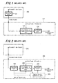
- FIGS. 1 and 2 are block diagrams showing examples in related art in which such video signal coding systems for network transmission are configured using a combination of AV apparatuses, respectively.
- an apparatus on the side of encoding video signals such as a PC, network-supported television receiver and STB is herein termed a “signal conversion apparatus” and an apparatus on the side of supplying the video signals to the “signal conversion apparatus", such as a video camera and VTR is herein termed a "video output apparatus”.
- FIG. 1 shows an example in which a decoding unit 101 in a video output apparatus 100 decodes a video signal encoded using, for example, the MPEG-2 into a video signal such as an uncompressed composite signal. Subsequently, the uncompressed video signal is output from the video output apparatus 100 and input into a signal conversion apparatus 102.
- the input video signal is first supplied to a size/number of frames converting unit 103 in the signal conversion apparatus 102.
- the size/number of frames converting unit 103 reduces a screen size and the number of frames of the video signals based on size/frame information (information specifying the screen size and the number of frames corresponding to a display apparatus on the other end of video phone), thereby reducing the volume of video signals to be suitable for network transmission.
- the video signals the volume of which is thus reduced are encoded by an encoding unit 104 using a coding method for video phone (for example, H.261 and MPEG-4 Part 10 (AVC)), and transmitted to the network from a network interface (not illustrated).
- a coding method for video phone for example, H.261 and MPEG-4 Part 10 (AVC)
- FIG. 2 shows an example in which a video signal encoded using the MPEG-2 or the like is output from a video output apparatus 200 and input into a signal conversion apparatus 201.
- the encoded video signal is first decoded by a decoding unit 202 and afterward supplied to a size/number of frames converting unit 203 in the signal conversion apparatus 201.
- the size/number of frames converting unit 203 reduces a screen size and the number of frames of the video signals based on size/frame information, thereby reducing the volume of video signals to be suitable for network transmission.
- the video signals the volume of which is thus reduced are encoded by an encoding unit 204 using a coding method for video phone, and transmitted to the network from a network interface (not illustrated). (A motion vector converting unit 205 is described later.)
- video phone, video conference, and remote security monitoring may require highly efficient encoding for real-time video transmission.
- a method using a motion vector is generally used as a highly efficient coding method, however processing of detecting the motion vector at the time of encoding may require a huge amount of calculation that is more than half the whole encoding processing.
- Japanese Unexamined Patent Application Publication No. 2001-238218 discloses the following technology with respect to the case where the encoded video signal is input into the signal conversion apparatus as shown in the example of the configuration according to FIG. 2.
- the motion vector converting unit 205 is provided to convert a motion vector output from the decoding unit 202 into a motion vector corresponding to the coding method implemented in the encoding unit 204 (and corresponding to the reduced screen size and number of frames specified by the size/frame information). Accordingly, the calculation cost necessary for the encoding is reduced in comparison to such a case that the motion vector is detected from scratch.
- the signal conversion apparatus 201 may need to include the decoding unit 202 corresponding to the coding method of the video signal (for example, MPEG) implemented in the video output apparatus 200. Therefore, AV apparatuses that can be used as the signal conversion apparatus 210 are limited to those corresponding to the coding method implemented in the AV apparatus used as the video output apparatus 200. Accordingly, other AV apparatuses are prevented from representing the configuration shown in FIG. 2.
- the decoding unit 202 corresponding to the coding method of the video signal (for example, MPEG) implemented in the video output apparatus 200. Therefore, AV apparatuses that can be used as the signal conversion apparatus 210 are limited to those corresponding to the coding method implemented in the AV apparatus used as the video output apparatus 200. Accordingly, other AV apparatuses are prevented from representing the configuration shown in FIG. 2.
- the video output apparatus 200 is, for example, a camcorder including a high resolution CCD camera having a large number of pixels, and a video signal output from the CCD camera is encoded with a high compression ratio and output from the video output apparatus 200
- a large processing capacity may also be required for decoding the high-compression video signal in the decoding unit 202 included in the signal conversion apparatus 201. Therefore, also in that case, a product price may be raised, and further a large amount of power consumption due to such processing may be inconvenient for a consumer.
- highly efficient encoding can be performed without providing a large-scale circuit consuming large power for detecting the motion vector in the signal conversion apparatus and without providing a decoding unit in the signal conversion apparatus as shown in the example according to FIG. 2.
- a video signal coding system for network transmission including: a video output apparatus and a signal conversion apparatus.
- the video output apparatus includes a decoding unit configured to decode a compressed video signal encoded by a coding method using a motion vector, and a superimposing unit configured to superimpose reference control information being output from the decoding unit and containing at least a motion vector on a blanking period of the video signal decoded by the decoding unit.
- the video output apparatus outputs the video signal with the reference control information superimposed by the superimposing unit.
- the signal conversion apparatus includes: a separating unit, an encoding unit, and a motion vector converting unit, and the encoding unit performs encoding using a motion vector converted by the motion vector converting unit.
- the reference control information is separated from the blanking period of the video signal that is input from the video output apparatus.
- the video signal separated from the reference control information by the separating unit is encoded by the coding method using the motion vector.
- the motion vector converting unit the motion vector contained in the reference control information separated by the separating unit is converted into the motion vector corresponding to the coding method implemented in the encoding unit.
- the video output apparatus including the decoding unit performs processing of superimposing the reference control information being output from the decoding unit and containing at least the motion vector on the blanking period of the decoded video signal. Subsequently, the video signal with the reference control information superimposed is output from the video output apparatus.
- the signal conversion apparatus performs processing of separating the reference control information from the blanking period of the video signal input from the video output apparatus. Further, the signal conversion apparatus performs processing of converting the motion vector contained in the separated reference control information into the motion vector corresponding to the coding method implemented in the encoding unit. Subsequently, the video signal separated from the reference control information is encoded using the converted motion vector in the encoding unit included in the signal conversion apparatus.
- the motion vector is superimposed on the blanking period of the video signal in the video output apparatus to be output, and the motion vector separated from the video signal is converted according to the coding method implemented in the internal coding circuit and used in the signal conversion apparatus. Accordingly, highly efficient encoding can be performed using the motion vector in the signal conversion apparatus without providing a large-scale circuit consuming large power for detecting the motion vector in the signal conversion apparatus, although the two apparatuses of the video output apparatus and signal conversion apparatus are separately provided from each other.
- the uncompressed video signal is output from the video output apparatus, there is no need for the signal conversion apparatus to be provided with the decoding unit corresponding to the method of coding the video signal implemented in the video output apparatus. Therefore, an AV apparatus not corresponding to the coding method implemented in the video output apparatus can be used as the signal conversion apparatus.
- the video signal for network transmission is output from a video output apparatus including a decoding unit configured to decode a compressed video signal encoded by a coding method using a motion vector, and the output video signal is input into a signal conversion apparatus that encodes the input video signal for network transmission.
- the method includes the steps of:
- the method of coding a video signal corresponds to a series of processing steps performed in the above-described video signal coding system according to this aspect of the present invention, and highly efficient coding using the motion vector can be performed in the signal conversion apparatus without providing a large-scale circuit consuming high power for motion vector detection.
- an AV apparatus not supporting the coding method implemented in the video output apparatus can also be used as the signal conversion apparatus.
- an output apparatus including a encoding unit and a superimposing unit, and outputting the video signal with the reference control information superimposed by the superimposing unit.
- the encoding unit is configured to encode a video signal supplied from an imaging device by a coding method using a motion vector.
- the superimposing unit is configured to superimpose reference control information being output from the encoding unit and containing at least a motion vector on a blanking period of the video signal supplied from the imaging device.
- the video output apparatus performs processing of superimposing the reference control information being output from the encoding unit that encodes the video signal and containing at least the motion vector on the blanking period of the video signal supplied from the imaging device. Subsequently, the video signal with the reference control information superimposed is output from the video output apparatus.
- the video output apparatus is set to collaborate with the signal conversion apparatus included in the above-described video signal coding system according to an embodiment of the present invention
- highly efficient coding using the motion vector can be performed in the signal conversion apparatus on a video signal currently obtained by the imaging device.
- an AV apparatus not supporting the coding method implemented in the video output apparatus can also be used as the signal conversion apparatus.
- a signal conversion apparatus including: a separating unit, an encoding unit, and a motion vector converting unit, in which the encoding unit performs encoding using a motion vector converted by the motion vector converting unit.
- the separating unit separates reference control information containing at least a motion vector from a blanking period of an input video signal.
- the encoding unit encodes the video signal separated from the reference control information by the separating unit by the coding method using the motion vector.
- the motion vector converting unit converts the motion vector contained in the reference control information separated by the separating unit into the motion vector corresponding to the coding method implemented in the encoding unit.
- the signal conversion apparatus is included in the above-described video signal coding system according to an aspect of the present invention, and highly efficient coding using the motion vector can be performed in the signal conversion apparatus when being set to collaborate with the above-described video output apparatus. In this regard, there is no need to provide a large-scale circuit consuming large power for motion vector detection in the signal conversion apparatus.
- an AV apparatus not supporting the coding method implemented in the video output apparatus can also be used as the signal conversion apparatus.
- a video signal coding system for network transmission is obtained using AV apparatuses in combination and the system includes two apparatuses of a video output apparatus and signal conversion apparatus separately provided
- the following advantages are obtained. Specifically, highly efficient coding using the motion vector can be performed in the signal conversion apparatus without providing a large-scale circuit consuming large power for motion vector detection in the signal conversion apparatus.
- an AV apparatus not supporting the coding method implemented in the video output apparatus can also be used as the signal conversion apparatus since the uncompressed video signal is output from the video output apparatus.
- a video output apparatus using a video output apparatus according to an embodiment of the present invention, highly efficient encoding using the motion vector can be performed in the signal conversion apparatus on a video signal being currently obtained by the imaging device.
- FIG. 3 is a block diagram showing an example of a configuration of a video signal coding system for network transmission, to which an embodiment of the present invention is applied.
- the system is provided to encode video signals transmitted through a network for video phone (or video conference or remote security monitoring), and the system is configured to have a video output apparatus 1 and a signal conversion apparatus 8.
- a camcorder is used as the video output apparatus 1, for example.
- a network-supported television receiver is used as the signal conversion apparatus 8, for example.
- the video output apparatus 1 includes: an imaging unit (for example, CCD camera) 2, encoding unit 3, superimposing unit 4, large capacity memory device (for example, hard disk drive) 5 and decoding unit 6 as circuits and devices related to an embodiment of the present invention.
- a video signal received from the imaging unit 2 is supplied to the encoding unit 3 and superimposing unit 4.
- the encoding unit 3 is, for example, an encoder of the MPEG-2 standard, configuration of which has been known, and therefore only the schematic configuration is illustrated in the figure.
- a coding method based on the MPEG-2 standard represents an example of a coding method using a motion vector, and a video signal conforming to the MPEG-2 standard is an example of a compressed video signal.
- a frame encoding unit 3-1 encodes a frame of the video signals supplied from the imaging unit 2.
- a frame decoding/memory unit 3-2 decodes the encoded video frame and temporarily stores the decoded frame.
- a motion vector detecting unit 3-3 detects video blocks of the same type between the frame of the video signal supplied from the imaging unit 2 and the frame previously stored in the frame decoding/memory unit 3-2, and a positional relationship between these video blocks is detected as a motion vector, which is supplied to a motion compensation unit 3-4.
- the motion compensation unit 3-4 performs motion prediction (compensation) on the frame previously stored in the frame decoding/memory unit 3-2 using the supplied motion vector, and the motion-predicted frame is supplied to the frame encoding unit 3-1.
- the frame encoding unit 3-1 uses the motion-predicted frame to encode a difference from the frame of the video signals supplied from the imaging unit 2.
- the video signal supplied from the imaging unit 2 is encoded by the encoding unit 3. Further, the motion vector detected by the motion vector detecting unit 3-3, and information on a macroblock type, picture type, picture size and frame rate and the like generated from the processing performed by the frame encoding unit 3-1 is supplied to the superimposing unit 4 from the encoding unit 3 as reference control information.
- the control panel when the control panel is operated to record the video signal currently obtained with the imaging unit 2, the video signal supplied from the imaging unit 2 is encoded in the encoding unit 3 and the encoded video signal is stored in the large capacity memory device 5 included in the video output apparatus 1.
- the decoding unit 6 is a decoder of the same coding standard as the encoding unit 3, a configuration of which has been known, and therefore a detailed description thereof is omitted.
- the video signal decoded by the decoding unit 6 is supplied to the superimposing unit 4.
- the information on a motion vector, macroblock type, picture type, picture size, frame rate and the like obtained at decoding in the decoding unit 6, is supplied to the superimposing unit 4 as the reference control information from the decoding unit 6.
- the superimposing unit 4 is a circuit that performs processing of superimposing the reference control information on the blanking period of the video signal output from the video output apparatus 1.
- the reference control information is supplied from the encoding unit 3 to the superimposing unit 4 as described above, and the superimposing unit 4 superimposes the supplied reference control information on the video signal supplied from the imaging unit 2.
- the reference control information is supplied from the decoding unit 6 to the superimposing unit 4 as described above, and the superimposing unit 4 superimposes the supplied reference control information on the video signal decoded in the decoding unit 6.
- the video signal with the reference control information superimposed by the superimposing unit 4 is output from the video output apparatus 1, and transmitted to the signal conversion apparatus 8 through a video cable 7.
- the signal conversion apparatus 8 includes a separating unit 9, size/number of frames converting unit 10, motion vector converting unit 11, encoding unit 12 and network interface 13 as circuits related to an embodiment of the present invention.
- the encoding unit 12 is an encoder of a coding standard for video phone (for example, H. 261 and MPEG-4 Part 10 (AVC)).
- the video signal input into the signal conversion apparatus 8 through the video cable 7 is supplied to the separating unit 9.
- the separating unit 9 is a circuit that performs processing of separating the above-described reference control information from the blanking period of the supplied video signal.
- a transmission mode of the video signal transmitted from the video output apparatus 1 to the signal conversion apparatus 8 may be an analogue signal such as a composite signal, or a digital signal.
- the imposing unit 4 may superimpose the reference control information on a line not used for text broadcasting in a vertical blanking interval; the video cable 7 may be a composite video cable or the like generally used; and the separating unit 9 separates the reference control information from the above-described line.
- HDMI High Definition Multimedia Interface
- the reference control information may be superimposed as described below.
- FIG. 4 is a schematic diagram showing devices conforming to the HDMI standard.
- An HDMI transmitter 22 transmitting a video signal is provided to an HDMI source 21.
- the HDMI transmitter 22 encodes respective supplied signals of video (video signal), audio/AUX (Auxiliary) and control/status into serial data on three TDMS (Transition Minimized Differential Signaling) channels 0 through 2 to be output, and also outputs a pixel clock of the video from a TMDS clock channel.
- TDMS Transition Minimized Differential Signaling
- the data on those channels, data on a DDC (Display Data Channel) for supplying specific information (resolution and the like) regarding a display, and a control signal for bidirectional control based on CEC (Consumer Electronics Control) protocol, which is option, are transmitted to an HDMI sink 23 receiving the video signal from the HDMI source 21 using one cable (HDMI cable).
- DDC Display Data Channel
- CEC Consumer Electronics Control
- An HDMI receiver 24 is provided to the HDMI sink 23.
- the HDMI receiver 24 restores respective signals of the original video, audio/AUX and control/status from the serial data on the TMDS channels 0 through 2 by referring to the pixel clock transmitted on the TDMS clock channel.
- FIG. 5 is a diagram showing an example (in the case where an active video is composed of 720 x 480 pixels) of a data island period that is a period of transmitting the audio/AUX in a video frame in the HDMI.
- the data island periods are dispersedly located at specific pixel positions in a horizontal blanking period of 138 pixels of each active line and in vertical blanking period of 45 lines, respectively.
- the imposing unit 4 and the separating unit 9 may be respectively configured as part of the HDMI transmitter 22 and HDMI receiver 24 shown in FIG. 4 conforming to the HDMI standard.
- the imposing unit 4 may superimpose the reference control information as a kind of AUX data on the data island period shown in FIG. 5, and the separating unit 9 may separate the reference control information from the data island period. Accordingly, an embodiment of the present invention can also be applied to the case where the video output apparatus 1 and signal conversion apparatus 8 are the devices that input and output the video signals conforming to the HDMI standard.
- the video signal separated from the reference control information by the separating unit 9 and the information on the picture size and frame rate contained in the reference control information are supplied to the size/number of frames converting unit 10 in the signal conversion apparatus 8. Further, the information on a motion vector, macroblock type and picture type that is contained in the reference control information separated by the separating unit 9 is supplied to the motion vector converting unit 11.
- the size/number of frames converting unit 10 reduces the screen size and the number of frames of video signals based on size/frame information (information specifying the screen size and the number of frames corresponding to a display apparatus on the other end of video phone), thereby reducing the volume of the video signals to be suitable for the network transmission.
- the video signals the volume of which is thus reduced are supplied to the encoding unit 12 from the size/number of frames converting unit 10.
- the motion vector converting unit 11 performs processing of converting the size of the motion vector and the like on the motion vector contained in the reference control information.
- the processing is performed corresponding to the coding method implemented in the encoding unit 12 and to the reduced screen size and number of frames reduced as specified by the size/frame information.
- the motion vector and the like thus converted are supplied to the encoding unit 12 from the motion vector converting unit 11.
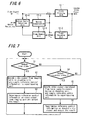
- FIG. 6 is a block diagram showing a configuration of the encoding unit 12.
- the basic configuration of the encoding unit 12 is common to an encoder of a normal coding standard for video phone, and includes a frame encoding unit 12-1, frame decoding unit 12-2, frame memory unit 12-3, motion vector detecting unit 12-4 and motion compensation unit 12-5.
- the frame encoding unit 12-1 encodes the frame of the video signals supplied from the size/number of frames converting unit 10.
- the frame decoding unit 12-2 decodes the encoded video frame.
- the frame memory unit 12-3 temporarily stores the decoded frame.
- the motion vector detecting unit 12-4 supplies the motion compensation unit 12-5 with a motion vector indicating a positional relationship of video blocks of the same type between the frame of the video signal supplied from the size/number of frames converting unit 10 and a frame previously stored in the frame memory unit 12-3.
- the motion vector detecting unit 12-4 instead of performing the processing of detecting the motion vector from scratch based on the video signal supplied from the size/number of frames converting unit 10, the motion vector detecting unit 12-4 omits the detection of the motion vector overlapping with the motion vector supplied to the encoding unit 12 from the motion vector converting unit 11.
- the motion vector detecting unit 12-4 performs processing of detecting a motion vector of a block having a different size from the supplied motion vector using the motion vector supplied from the motion vector converting unit 11, and processing of detecting motion vectors surrounding the supplied motion vector by referring to the motion vector supplied from the motion vector converting unit 11. Accordingly, the motion vector detecting unit 12-4 only needs a small-scale circuit and less power consumption in comparison to the case where the motion vector is detected from scratch, and furthermore a detailed motion vector detection can be performed.
- the motion compensation unit 12-5 performs the motion prediction (compensation) for a frame previously stored in the frame memory unit 12-3 using the motion vector supplied from the motion vector detecting unit 12-4.
- the frame encoding unit 12-1 uses the motion-predicted frame for encoding a difference from the frame of the video signals output from the size/number of frames converting unit 10.
- the video signals encoded by the encoding unit 12 with the coding method for video phone are transmitted to a network 14 from the network interface 13 as shown in FIG. 3, thereby transmitting the encoded video signals to a device (not illustrated) on the other end of video phone via the network 14.
- FIGS. 7 and 8 are flow charts showing processing steps performed in the video output apparatus 1 and signal conversion apparatus 8 according to FIG. 3, respectively. Further, FIG. 9 is a flow chart showing processing steps performed in the encoding unit 12 included in the signal conversion apparatus 8.
- the encoding unit 3 encodes the video signal supplied from the imaging unit 2, and supplies the reference control information obtained through encoding to the superimposing unit 4 in the video output apparatus 1 (step S2).
- the superimposing unit 4 superimposes the reference control information supplied from the encoding unit 3 on the blanking period of the video signal supplied from the imaging unit 2, and outputs the video signal from the video output apparatus 1 (step S3). Then, the processing returns to step S1.
- the decoding unit 6 decodes the encoded video signal reproduced from the large capacity memory device 5 and supplies the decoded signal to the superimposing unit 4, and also supplies the reference control information obtained through decoding to the superimposing unit 4 (step S5).
- the superimposing unit 4 superimposes the reference control information supplied from the decoding unit 6 on the blanking period of the decoded video signal, and outputs the video signal from the video output apparatus 1 (step S6). Then, the processing returns to step S1.
- the separating unit 9 in the signal conversion apparatus 8 retrieves the reference control information superimposed on the blanking period of the input video signal, thereby separating the reference control information from the video signal (step S11). Subsequently, the size/number of frames converting unit 10 adjusts the screen size and the number of frames based on the size/frame information, thereby adjusting the video signals separated from the reference control information to a signal volume suitable for the transmission via the network (step S12). Further, the motion vector converting unit 11 converts the motion vector contained in the separated reference control information in accordance with the coding method implemented in the encoding unit 12 and reduced screen size and number of frames, which are specified by the size/frame information (step S13).
- the encoding unit 12 encodes the video signal after the screen size and number of frames have been adjusted by the processing described in FIG. 9 (step S14). Then, the processing returns to step S11 and is repeated to subsequent input video signals.
- the encoding unit 12 checks whether or not a picture type of the input video signal is intra-picture coding (I-picture) based on the picture type information contained in the reference control information (step S21).
- the frame encoding unit 12-1 performs frame-encoding on the input video signals (step S22), reorders and outputs the video signals to be decoded in the same order in a decoding unit in a device on the other end of transmission (step S23).
- the frame decoding unit 12-2 decodes the video that is frame-encoded by the frame encoding unit 12-1 (step S24), and the frame memory unit 12-3 temporarily stores the decoded video as a reference picture (step S25). Then, the processing returns to step S21 and is repeated on subsequent input video signals.
- the motion vector detecting unit 12-4 performs motion vector detection processing of detecting the same video blocks between the video that has been stored in the frame memory unit 12-3 and video that is newly input.
- the motion vector supplied from the motion vector converting unit 11 is used so that the overlapped motion vector is prevented from being detected, and only a motion vector not contained in the reference control information is additionally detected by detecting a block having a different size and surrounding motion vectors (step S26).
- the motion compensation unit 12-5 performs the motion prediction (compensation) for the frame previously stored in the frame memory unit 12-3 using the motion vector supplied from the motion vector detecting unit 12-4, and the frame encoding unit 12-1 performs the frame-encoding on a difference between the motion-predicted frame and the frame of the video signal supplied from the size/number of frames converting unit 10 (step S27). Then, the frame encoding unit 12-1 reorders and outputs the frame-encoded video to be decoded in the same order in a decoding unit in a device on the other end of transmission (step S28).
- the frame decoding unit 12-2 decodes the video that is frame-encoded by the frame encoding unit 12-1 (step S29).
- the frame memory unit 12-3 temporarily stores the video obtained by adding the differential video obtained by the above decoding to the motion-compensated video previously obtained when taking the difference, more specifically, the same video as the video that can be obtained by decoding in the decoding unit included in the device on the other end of transmission (step S30). Then, the processing returns to step S21 and is repeated on subsequent input video signals.
- the video signals are output as follows. Specifically, reference control information such as a motion vector is obtained in the encoding unit 3 by encoding the video signal supplied from the imaging unit 2, and is superimposed on the blanking period of the video signal supplied from the imaging unit 2 in the video output apparatus 1, thereby outputting the video signal with the reference control information superimposed.
- the video signal is output after the processing described below is performed.
- reference control information such as the motion vector obtained by decoding the encoded video signal reproduced from the large capacity memory device 5 in the decoding unit 6 is superimposed on the blanking period of the decoded video signal in the video output apparatus 1, thereby outputting the video signal with the reference control information superimposed.
- the reference control information containing the motion vector is superimposed on the blanking period of the video signal that is output from the video output apparatus 1 in both the cases of transmitting the live video and recorded video.
- the motion vector contained in the reference control information separated from the input video signal is converted into the motion vector corresponding to the coding method for video phone, and the input video signal is encoded using the converted motion vector, thereby transmitting the encoded video signal to the network.
- the two apparatuses of the video output apparatus 1 and signal conversion apparatus 8 are provided separately from each other, the highly efficient encoding can be performed in both the cases of transmitting the live video and recorded video via the network, using the motion vector in the signal conversion apparatus 8 without providing a large-scale circuit consuming large power for motion vector detection in the signal conversion apparatus 8.
- the signal conversion apparatus 8 since the uncompressed video signals are output from the video output apparatus 1, there is no need for the signal conversion apparatus 8 to be provided with a decoding unit corresponding to the method of coding the video signal (for example, MPEG-2) implemented in the video output apparatus 1. Therefore, an AV apparatus not corresponding to the coding method implemented in the video output apparatus 1 can also be used as the signal conversion apparatus 8.
Abstract
Description
- The present invention contains subject matter related to
Japanese Patent Application JP 2006-081618 - The present invention relates to a system, method and apparatus in which encoding using a motion vector can be performed efficiently in the case of using AV apparatuses in combination to encode a video signal for network transmission.
- In general, using Internet and other networks, live video currently obtained from, for example, video phone, video conference and remote security monitoring is transmitted, and recorded video, for example, a video content is also transmitted to be distributed. Such transmission of video via networks has been performed using dedicated terminals, but lately AV apparatuses such as a video camera, VTR, PC (Personal Computer), network-supported television receiver, STB (Set-Top Box) and telephone unit have been combined to transmit such video.
- In order to transmit video signals via a network, the video signals are normally encoded and compressed before being transmitted to the network in relation to a bandwidth of the network. For example, when a system in which a video signal is encoded for video phone is obtained using one dedicated terminal incorporating an imaging unit such as CCD camera and an encoding circuit, the dedicated terminal can be designed to balance the volume of video signals with encoding processing in processing steps where the video signal supplied from the imaging unit is encoded using the encoding circuit to be transmitted.
- On the other hand, in the case where a video camera or the like is used as the imaging unit, and a PC and network-supported television receiver are used as the encoding circuit, the video signal coding system for video phone is obtained using these apparatuses. In such case, the volume of video signals and encoding processing are not necessarily optimized, since these apparatuses are originally made for different purposes.
- FIGS. 1 and 2 are block diagrams showing examples in related art in which such video signal coding systems for network transmission are configured using a combination of AV apparatuses, respectively. It should be noted that an apparatus on the side of encoding video signals, such as a PC, network-supported television receiver and STB is herein termed a "signal conversion apparatus" and an apparatus on the side of supplying the video signals to the "signal conversion apparatus", such as a video camera and VTR is herein termed a "video output apparatus".
- FIG. 1 shows an example in which a
decoding unit 101 in avideo output apparatus 100 decodes a video signal encoded using, for example, the MPEG-2 into a video signal such as an uncompressed composite signal. Subsequently, the uncompressed video signal is output from thevideo output apparatus 100 and input into asignal conversion apparatus 102. - The input video signal is first supplied to a size/number of
frames converting unit 103 in thesignal conversion apparatus 102. The size/number offrames converting unit 103 reduces a screen size and the number of frames of the video signals based on size/frame information (information specifying the screen size and the number of frames corresponding to a display apparatus on the other end of video phone), thereby reducing the volume of video signals to be suitable for network transmission. The video signals the volume of which is thus reduced are encoded by anencoding unit 104 using a coding method for video phone (for example, H.261 and MPEG-4 Part 10 (AVC)), and transmitted to the network from a network interface (not illustrated). - FIG. 2 shows an example in which a video signal encoded using the MPEG-2 or the like is output from a
video output apparatus 200 and input into asignal conversion apparatus 201. - The encoded video signal is first decoded by a
decoding unit 202 and afterward supplied to a size/number offrames converting unit 203 in thesignal conversion apparatus 201. The size/number offrames converting unit 203 reduces a screen size and the number of frames of the video signals based on size/frame information, thereby reducing the volume of video signals to be suitable for network transmission. The video signals the volume of which is thus reduced are encoded by anencoding unit 204 using a coding method for video phone, and transmitted to the network from a network interface (not illustrated). (A motionvector converting unit 205 is described later.) - Among video transmissions through networks, in particular, video phone, video conference, and remote security monitoring may require highly efficient encoding for real-time video transmission. A method using a motion vector is generally used as a highly efficient coding method, however processing of detecting the motion vector at the time of encoding may require a huge amount of calculation that is more than half the whole encoding processing.
- Therefore, in the case where the uncompressed video signal is input into the
signal conversion apparatus 102 as shown in the example of the configuration according to FIG. 1, a large-scale circuit that performs a great amount of calculation for detecting the motion vector may need to be provided in theencoding unit 104. As a result, not only the cost of such large-scale circuit raises a product price, but also a large amount of power consumption caused by this circuit may be inconvenient for a consumer. -
Japanese Unexamined Patent Application Publication No. 2001-238218 vector converting unit 205 is provided to convert a motion vector output from thedecoding unit 202 into a motion vector corresponding to the coding method implemented in the encoding unit 204 (and corresponding to the reduced screen size and number of frames specified by the size/frame information). Accordingly, the calculation cost necessary for the encoding is reduced in comparison to such a case that the motion vector is detected from scratch. - However, in the configuration according to FIG. 2, the
signal conversion apparatus 201 may need to include thedecoding unit 202 corresponding to the coding method of the video signal (for example, MPEG) implemented in thevideo output apparatus 200. Therefore, AV apparatuses that can be used as the signal conversion apparatus 210 are limited to those corresponding to the coding method implemented in the AV apparatus used as thevideo output apparatus 200. Accordingly, other AV apparatuses are prevented from representing the configuration shown in FIG. 2. - Further, in the case where the
video output apparatus 200 is, for example, a camcorder including a high resolution CCD camera having a large number of pixels, and a video signal output from the CCD camera is encoded with a high compression ratio and output from thevideo output apparatus 200, a large processing capacity may also be required for decoding the high-compression video signal in thedecoding unit 202 included in thesignal conversion apparatus 201. Therefore, also in that case, a product price may be raised, and further a large amount of power consumption due to such processing may be inconvenient for a consumer. - As described above, in the case where a video signal coding system for network transmission is obtained using AV apparatuses in combination and the system includes two apparatuses of a video output apparatus and signal conversion apparatus separately provided, a suitable method for the signal conversion apparatus to perform efficient encoding has not been provided. Therefore, configuration of apparatuses, product price, power consumption, communication quality, and the like have been not necessarily user-friendly.
- It is desirable to provide a video signal coding system for network transmission in which highly efficient encoding can be performed using a motion vector in a signal conversion apparatus, in the case where the video signal coding system is obtained using AV apparatuses in combination and the system includes two apparatuses of a video output apparatus and the signal conversion apparatus separately provided. In the video signal coding system, highly efficient encoding can be performed without providing a large-scale circuit consuming large power for detecting the motion vector in the signal conversion apparatus and without providing a decoding unit in the signal conversion apparatus as shown in the example according to FIG. 2.
- According to one aspect of the present invention, there is provided a video signal coding system for network transmission including: a video output apparatus and a signal conversion apparatus. The video output apparatus includes a decoding unit configured to decode a compressed video signal encoded by a coding method using a motion vector, and a superimposing unit configured to superimpose reference control information being output from the decoding unit and containing at least a motion vector on a blanking period of the video signal decoded by the decoding unit. The video output apparatus outputs the video signal with the reference control information superimposed by the superimposing unit. The signal conversion apparatus includes: a separating unit, an encoding unit, and a motion vector converting unit, and the encoding unit performs encoding using a motion vector converted by the motion vector converting unit. In the separating unit, the reference control information is separated from the blanking period of the video signal that is input from the video output apparatus. In the encoding unit, the video signal separated from the reference control information by the separating unit is encoded by the coding method using the motion vector. In the motion vector converting unit, the motion vector contained in the reference control information separated by the separating unit is converted into the motion vector corresponding to the coding method implemented in the encoding unit.
- In the above-described video signal coding system, the video output apparatus including the decoding unit performs processing of superimposing the reference control information being output from the decoding unit and containing at least the motion vector on the blanking period of the decoded video signal. Subsequently, the video signal with the reference control information superimposed is output from the video output apparatus.
- The signal conversion apparatus performs processing of separating the reference control information from the blanking period of the video signal input from the video output apparatus. Further, the signal conversion apparatus performs processing of converting the motion vector contained in the separated reference control information into the motion vector corresponding to the coding method implemented in the encoding unit. Subsequently, the video signal separated from the reference control information is encoded using the converted motion vector in the encoding unit included in the signal conversion apparatus.
- As described above, the motion vector is superimposed on the blanking period of the video signal in the video output apparatus to be output, and the motion vector separated from the video signal is converted according to the coding method implemented in the internal coding circuit and used in the signal conversion apparatus. Accordingly, highly efficient encoding can be performed using the motion vector in the signal conversion apparatus without providing a large-scale circuit consuming large power for detecting the motion vector in the signal conversion apparatus, although the two apparatuses of the video output apparatus and signal conversion apparatus are separately provided from each other.
- In addition, since the uncompressed video signal is output from the video output apparatus, there is no need for the signal conversion apparatus to be provided with the decoding unit corresponding to the method of coding the video signal implemented in the video output apparatus. Therefore, an AV apparatus not corresponding to the coding method implemented in the video output apparatus can be used as the signal conversion apparatus.
- Next, according to another aspect of the present invention, there is provided a method of coding a video signal for network transmission. Using the method, the video signal for network transmission is output from a video output apparatus including a decoding unit configured to decode a compressed video signal encoded by a coding method using a motion vector, and the output video signal is input into a signal conversion apparatus that encodes the input video signal for network transmission. The method includes the steps of:
- superimposing in the video output apparatus reference control information being output from the decoding unit and containing at least a motion vector on a blanking period of the video signal decoded by the decoding unit;
- separating in the signal conversion apparatus the reference control information from the blanking period of the video signal input from the video output apparatus;
- converting in the signal conversion apparatus the motion vector contained in the reference control information separated at the separating step into a motion vector corresponding to a specific coding method using a motion vector implemented in the signal conversion apparatus; and
- encoding in the signal conversion apparatus the video signal separated from the reference control information at the separating step by the specific coding method using the motion vector converted at the converting step.
- The method of coding a video signal corresponds to a series of processing steps performed in the above-described video signal coding system according to this aspect of the present invention, and highly efficient coding using the motion vector can be performed in the signal conversion apparatus without providing a large-scale circuit consuming high power for motion vector detection. In addition, an AV apparatus not supporting the coding method implemented in the video output apparatus can also be used as the signal conversion apparatus.
- Next, according to a further aspect of the present invention, there is provided an output apparatus including a encoding unit and a superimposing unit, and outputting the video signal with the reference control information superimposed by the superimposing unit. The encoding unit is configured to encode a video signal supplied from an imaging device by a coding method using a motion vector. The superimposing unit is configured to superimpose reference control information being output from the encoding unit and containing at least a motion vector on a blanking period of the video signal supplied from the imaging device.
- The video output apparatus performs processing of superimposing the reference control information being output from the encoding unit that encodes the video signal and containing at least the motion vector on the blanking period of the video signal supplied from the imaging device. Subsequently, the video signal with the reference control information superimposed is output from the video output apparatus.
- Therefore, in the case where the video output apparatus is set to collaborate with the signal conversion apparatus included in the above-described video signal coding system according to an embodiment of the present invention, highly efficient coding using the motion vector can be performed in the signal conversion apparatus on a video signal currently obtained by the imaging device. In this regard, there is no need to provide a large-scale circuit consuming large power for motion vector detection in the signal conversion apparatus. In addition, an AV apparatus not supporting the coding method implemented in the video output apparatus can also be used as the signal conversion apparatus.
- Next, according to another aspect of the present invention, there is provided a signal conversion apparatus including: a separating unit, an encoding unit, and a motion vector converting unit, in which the encoding unit performs encoding using a motion vector converted by the motion vector converting unit. The separating unit separates reference control information containing at least a motion vector from a blanking period of an input video signal. The encoding unit encodes the video signal separated from the reference control information by the separating unit by the coding method using the motion vector. The motion vector converting unit converts the motion vector contained in the reference control information separated by the separating unit into the motion vector corresponding to the coding method implemented in the encoding unit.
- The signal conversion apparatus is included in the above-described video signal coding system according to an aspect of the present invention, and highly efficient coding using the motion vector can be performed in the signal conversion apparatus when being set to collaborate with the above-described video output apparatus. In this regard, there is no need to provide a large-scale circuit consuming large power for motion vector detection in the signal conversion apparatus. In addition, an AV apparatus not supporting the coding method implemented in the video output apparatus can also be used as the signal conversion apparatus.
- According to embodiments of the present invention, in the case where a video signal coding system for network transmission is obtained using AV apparatuses in combination and the system includes two apparatuses of a video output apparatus and signal conversion apparatus separately provided, the following advantages are obtained. Specifically, highly efficient coding using the motion vector can be performed in the signal conversion apparatus without providing a large-scale circuit consuming large power for motion vector detection in the signal conversion apparatus. In addition, an AV apparatus not supporting the coding method implemented in the video output apparatus can also be used as the signal conversion apparatus since the uncompressed video signal is output from the video output apparatus.
- Further, using a video output apparatus according to an embodiment of the present invention, highly efficient encoding using the motion vector can be performed in the signal conversion apparatus on a video signal being currently obtained by the imaging device.
- Embodiments of the invention will now be described, by way of example only, with reference to the accompanying drawings in which:
- FIG. 1 is a block diagram showing an example of a configuration of a video signal coding system for network transmission formed by a combination of AV apparatuses in related art;
- FIG. 2 is a block diagram showing an example of a configuration of a video signal coding system for network transmission formed by a combination of AV apparatuses in related art;
- FIG. 3 is a block diagram showing an example of a configuration of a video signal coding system for network transmission to which an embodiment of the present invention is applied;
- FIG. 4 is a schematic diagram showing a device that conforms to the HDMI standard;
- FIG. 5 is a diagram showing an example of a data island period contained in a video frame in the HDMI;
- FIG. 6 is a block diagram showing a configuration of an encoding unit included in a signal conversion apparatus;
- FIG. 7 is a flow chart showing processing in a video output apparatus;
- FIG. 8 is a flow chart showing processing in the signal conversion apparatus; and
- FIG. 9 is a flow chart showing processing in the encoding unit included in the signal converting unit.
- FIG. 3 is a block diagram showing an example of a configuration of a video signal coding system for network transmission, to which an embodiment of the present invention is applied. The system is provided to encode video signals transmitted through a network for video phone (or video conference or remote security monitoring), and the system is configured to have a
video output apparatus 1 and a signal conversion apparatus 8. A camcorder is used as thevideo output apparatus 1, for example. A network-supported television receiver is used as the signal conversion apparatus 8, for example. - The
video output apparatus 1 includes: an imaging unit (for example, CCD camera) 2, encoding unit 3, superimposingunit 4, large capacity memory device (for example, hard disk drive) 5 anddecoding unit 6 as circuits and devices related to an embodiment of the present invention. A video signal received from theimaging unit 2 is supplied to the encoding unit 3 and superimposingunit 4. - The encoding unit 3 is, for example, an encoder of the MPEG-2 standard, configuration of which has been known, and therefore only the schematic configuration is illustrated in the figure. A coding method based on the MPEG-2 standard represents an example of a coding method using a motion vector, and a video signal conforming to the MPEG-2 standard is an example of a compressed video signal. A frame encoding unit 3-1 encodes a frame of the video signals supplied from the
imaging unit 2. A frame decoding/memory unit 3-2 decodes the encoded video frame and temporarily stores the decoded frame. - A motion vector detecting unit 3-3 detects video blocks of the same type between the frame of the video signal supplied from the
imaging unit 2 and the frame previously stored in the frame decoding/memory unit 3-2, and a positional relationship between these video blocks is detected as a motion vector, which is supplied to a motion compensation unit 3-4. The motion compensation unit 3-4 performs motion prediction (compensation) on the frame previously stored in the frame decoding/memory unit 3-2 using the supplied motion vector, and the motion-predicted frame is supplied to the frame encoding unit 3-1. The frame encoding unit 3-1 uses the motion-predicted frame to encode a difference from the frame of the video signals supplied from theimaging unit 2. - When a control panel (not illustrated) of the
video output apparatus 1 is operated to output the video signal currently obtained with theimaging unit 2 from thevideo output apparatus 1, the video signal supplied from theimaging unit 2 is encoded by the encoding unit 3. Further, the motion vector detected by the motion vector detecting unit 3-3, and information on a macroblock type, picture type, picture size and frame rate and the like generated from the processing performed by the frame encoding unit 3-1 is supplied to thesuperimposing unit 4 from the encoding unit 3 as reference control information. - In addition, when the control panel is operated to record the video signal currently obtained with the
imaging unit 2, the video signal supplied from theimaging unit 2 is encoded in the encoding unit 3 and the encoded video signal is stored in the largecapacity memory device 5 included in thevideo output apparatus 1. - Also, when the control panel is operated to output the recorded video signal from the
video output apparatus 1, the video signal is reproduced from the largecapacity memory device 5 and the reproduced video signal is supplied to thedecoding unit 6. Thedecoding unit 6 is a decoder of the same coding standard as the encoding unit 3, a configuration of which has been known, and therefore a detailed description thereof is omitted. - The video signal decoded by the
decoding unit 6 is supplied to thesuperimposing unit 4. In addition, the information on a motion vector, macroblock type, picture type, picture size, frame rate and the like obtained at decoding in thedecoding unit 6, is supplied to thesuperimposing unit 4 as the reference control information from thedecoding unit 6. - The superimposing
unit 4 is a circuit that performs processing of superimposing the reference control information on the blanking period of the video signal output from thevideo output apparatus 1. When the operation to output the video signal currently obtained with theimaging unit 2 from thevideo output apparatus 1 is performed, the reference control information is supplied from the encoding unit 3 to thesuperimposing unit 4 as described above, and the superimposingunit 4 superimposes the supplied reference control information on the video signal supplied from theimaging unit 2. In addition, when the operation to output the recorded video signal from thevideo output apparatus 1 is performed, the reference control information is supplied from thedecoding unit 6 to thesuperimposing unit 4 as described above, and the superimposingunit 4 superimposes the supplied reference control information on the video signal decoded in thedecoding unit 6. - The video signal with the reference control information superimposed by the superimposing
unit 4 is output from thevideo output apparatus 1, and transmitted to the signal conversion apparatus 8 through a video cable 7. - The signal conversion apparatus 8 includes a
separating unit 9, size/number offrames converting unit 10, motionvector converting unit 11, encodingunit 12 andnetwork interface 13 as circuits related to an embodiment of the present invention. Theencoding unit 12 is an encoder of a coding standard for video phone (for example, H. 261 and MPEG-4 Part 10 (AVC)). - The video signal input into the signal conversion apparatus 8 through the video cable 7 is supplied to the
separating unit 9. The separatingunit 9 is a circuit that performs processing of separating the above-described reference control information from the blanking period of the supplied video signal. - It should be noted that a transmission mode of the video signal transmitted from the
video output apparatus 1 to the signal conversion apparatus 8 may be an analogue signal such as a composite signal, or a digital signal. In the case of the analogue video signal, the imposingunit 4 may superimpose the reference control information on a line not used for text broadcasting in a vertical blanking interval; the video cable 7 may be a composite video cable or the like generally used; and theseparating unit 9 separates the reference control information from the above-described line. - HDMI (High Definition Multimedia Interface) that is a standard for high quality transmission of uncompressed digital video signals has started to be used as a transmission standard for digital video signals. In the case where the
video output apparatus 1 and signal conversion apparatus 8 are devices that input and output a video signal conforming to the HDMI standard, the reference control information may be superimposed as described below. - FIG. 4 is a schematic diagram showing devices conforming to the HDMI standard. An
HDMI transmitter 22 transmitting a video signal is provided to anHDMI source 21. TheHDMI transmitter 22 encodes respective supplied signals of video (video signal), audio/AUX (Auxiliary) and control/status into serial data on three TDMS (Transition Minimized Differential Signaling)channels 0 through 2 to be output, and also outputs a pixel clock of the video from a TMDS clock channel. The data on those channels, data on a DDC (Display Data Channel) for supplying specific information (resolution and the like) regarding a display, and a control signal for bidirectional control based on CEC (Consumer Electronics Control) protocol, which is option, are transmitted to anHDMI sink 23 receiving the video signal from theHDMI source 21 using one cable (HDMI cable). - An
HDMI receiver 24 is provided to theHDMI sink 23. TheHDMI receiver 24 restores respective signals of the original video, audio/AUX and control/status from the serial data on theTMDS channels 0 through 2 by referring to the pixel clock transmitted on the TDMS clock channel. - FIG. 5 is a diagram showing an example (in the case where an active video is composed of 720 x 480 pixels) of a data island period that is a period of transmitting the audio/AUX in a video frame in the HDMI. The data island periods are dispersedly located at specific pixel positions in a horizontal blanking period of 138 pixels of each active line and in vertical blanking period of 45 lines, respectively.
- In the case where the
video output apparatus 1 and signal conversion apparatus 8 shown in FIG. 3 input and output video signals conforming to the HDMI standard (in other words, those apparatuses are the HDMI source and HDMI sink respectively), the imposingunit 4 and theseparating unit 9 may be respectively configured as part of theHDMI transmitter 22 andHDMI receiver 24 shown in FIG. 4 conforming to the HDMI standard. The imposingunit 4 may superimpose the reference control information as a kind of AUX data on the data island period shown in FIG. 5, and theseparating unit 9 may separate the reference control information from the data island period. Accordingly, an embodiment of the present invention can also be applied to the case where thevideo output apparatus 1 and signal conversion apparatus 8 are the devices that input and output the video signals conforming to the HDMI standard. - Returning to the description referring to FIG. 3, the video signal separated from the reference control information by the separating
unit 9 and the information on the picture size and frame rate contained in the reference control information are supplied to the size/number offrames converting unit 10 in the signal conversion apparatus 8. Further, the information on a motion vector, macroblock type and picture type that is contained in the reference control information separated by the separatingunit 9 is supplied to the motionvector converting unit 11. - The size/number of
frames converting unit 10 reduces the screen size and the number of frames of video signals based on size/frame information (information specifying the screen size and the number of frames corresponding to a display apparatus on the other end of video phone), thereby reducing the volume of the video signals to be suitable for the network transmission. The video signals the volume of which is thus reduced are supplied to theencoding unit 12 from the size/number offrames converting unit 10. - The motion
vector converting unit 11 performs processing of converting the size of the motion vector and the like on the motion vector contained in the reference control information. The processing is performed corresponding to the coding method implemented in theencoding unit 12 and to the reduced screen size and number of frames reduced as specified by the size/frame information. The motion vector and the like thus converted are supplied to theencoding unit 12 from the motionvector converting unit 11. - FIG. 6 is a block diagram showing a configuration of the
encoding unit 12. The basic configuration of theencoding unit 12 is common to an encoder of a normal coding standard for video phone, and includes a frame encoding unit 12-1, frame decoding unit 12-2, frame memory unit 12-3, motion vector detecting unit 12-4 and motion compensation unit 12-5. - The frame encoding unit 12-1 encodes the frame of the video signals supplied from the size/number of
frames converting unit 10. The frame decoding unit 12-2 decodes the encoded video frame. The frame memory unit 12-3 temporarily stores the decoded frame. - The motion vector detecting unit 12-4 supplies the motion compensation unit 12-5 with a motion vector indicating a positional relationship of video blocks of the same type between the frame of the video signal supplied from the size/number of
frames converting unit 10 and a frame previously stored in the frame memory unit 12-3. However, instead of performing the processing of detecting the motion vector from scratch based on the video signal supplied from the size/number offrames converting unit 10, the motion vector detecting unit 12-4 omits the detection of the motion vector overlapping with the motion vector supplied to theencoding unit 12 from the motionvector converting unit 11. Further, the motion vector detecting unit 12-4 performs processing of detecting a motion vector of a block having a different size from the supplied motion vector using the motion vector supplied from the motionvector converting unit 11, and processing of detecting motion vectors surrounding the supplied motion vector by referring to the motion vector supplied from the motionvector converting unit 11. Accordingly, the motion vector detecting unit 12-4 only needs a small-scale circuit and less power consumption in comparison to the case where the motion vector is detected from scratch, and furthermore a detailed motion vector detection can be performed. - The motion compensation unit 12-5 performs the motion prediction (compensation) for a frame previously stored in the frame memory unit 12-3 using the motion vector supplied from the motion vector detecting unit 12-4. The frame encoding unit 12-1 uses the motion-predicted frame for encoding a difference from the frame of the video signals output from the size/number of
frames converting unit 10. - The video signals encoded by the
encoding unit 12 with the coding method for video phone are transmitted to anetwork 14 from thenetwork interface 13 as shown in FIG. 3, thereby transmitting the encoded video signals to a device (not illustrated) on the other end of video phone via thenetwork 14. - FIGS. 7 and 8 are flow charts showing processing steps performed in the
video output apparatus 1 and signal conversion apparatus 8 according to FIG. 3, respectively. Further, FIG. 9 is a flow chart showing processing steps performed in theencoding unit 12 included in the signal conversion apparatus 8. - As shown in FIG. 7, in the case where the video signal supplied from the
imaging unit 2 is immediately output (more specifically, live video is output) ("YES" at step S1), the encoding unit 3 encodes the video signal supplied from theimaging unit 2, and supplies the reference control information obtained through encoding to thesuperimposing unit 4 in the video output apparatus 1 (step S2). The superimposingunit 4 superimposes the reference control information supplied from the encoding unit 3 on the blanking period of the video signal supplied from theimaging unit 2, and outputs the video signal from the video output apparatus 1 (step S3). Then, the processing returns to step S1. - On the other hand, in the case where the recorded video is output ("YES" at step S4), the
decoding unit 6 decodes the encoded video signal reproduced from the largecapacity memory device 5 and supplies the decoded signal to thesuperimposing unit 4, and also supplies the reference control information obtained through decoding to the superimposing unit 4 (step S5). The superimposingunit 4 superimposes the reference control information supplied from thedecoding unit 6 on the blanking period of the decoded video signal, and outputs the video signal from the video output apparatus 1 (step S6). Then, the processing returns to step S1. - As shown in FIG. 8, the separating
unit 9 in the signal conversion apparatus 8 retrieves the reference control information superimposed on the blanking period of the input video signal, thereby separating the reference control information from the video signal (step S11). Subsequently, the size/number offrames converting unit 10 adjusts the screen size and the number of frames based on the size/frame information, thereby adjusting the video signals separated from the reference control information to a signal volume suitable for the transmission via the network (step S12). Further, the motionvector converting unit 11 converts the motion vector contained in the separated reference control information in accordance with the coding method implemented in theencoding unit 12 and reduced screen size and number of frames, which are specified by the size/frame information (step S13). - Subsequently, using the converted motion vector, the
encoding unit 12 encodes the video signal after the screen size and number of frames have been adjusted by the processing described in FIG. 9 (step S14). Then, the processing returns to step S11 and is repeated to subsequent input video signals. - As shown in FIG. 9, the
encoding unit 12 checks whether or not a picture type of the input video signal is intra-picture coding (I-picture) based on the picture type information contained in the reference control information (step S21). In the case of the intra-picture coding, the frame encoding unit 12-1 performs frame-encoding on the input video signals (step S22), reorders and outputs the video signals to be decoded in the same order in a decoding unit in a device on the other end of transmission (step S23). - The frame decoding unit 12-2 decodes the video that is frame-encoded by the frame encoding unit 12-1 (step S24), and the frame memory unit 12-3 temporarily stores the decoded video as a reference picture (step S25). Then, the processing returns to step S21 and is repeated on subsequent input video signals.
- In the case where the picture type of the input video signal was not the intra-picture coding at step S21, the motion vector detecting unit 12-4 performs motion vector detection processing of detecting the same video blocks between the video that has been stored in the frame memory unit 12-3 and video that is newly input. Here, the motion vector supplied from the motion
vector converting unit 11 is used so that the overlapped motion vector is prevented from being detected, and only a motion vector not contained in the reference control information is additionally detected by detecting a block having a different size and surrounding motion vectors (step S26). - Subsequently, the motion compensation unit 12-5 performs the motion prediction (compensation) for the frame previously stored in the frame memory unit 12-3 using the motion vector supplied from the motion vector detecting unit 12-4, and the frame encoding unit 12-1 performs the frame-encoding on a difference between the motion-predicted frame and the frame of the video signal supplied from the size/number of frames converting unit 10 (step S27). Then, the frame encoding unit 12-1 reorders and outputs the frame-encoded video to be decoded in the same order in a decoding unit in a device on the other end of transmission (step S28).
- The frame decoding unit 12-2 decodes the video that is frame-encoded by the frame encoding unit 12-1 (step S29). The frame memory unit 12-3 temporarily stores the video obtained by adding the differential video obtained by the above decoding to the motion-compensated video previously obtained when taking the difference, more specifically, the same video as the video that can be obtained by decoding in the decoding unit included in the device on the other end of transmission (step S30). Then, the processing returns to step S21 and is repeated on subsequent input video signals.
- According to the above described video signal coding system, in the case where video signals (live video) being currently obtained with the
imaging unit 2 are transmitted via the network, the video signals are output as follows. Specifically, reference control information such as a motion vector is obtained in the encoding unit 3 by encoding the video signal supplied from theimaging unit 2, and is superimposed on the blanking period of the video signal supplied from theimaging unit 2 in thevideo output apparatus 1, thereby outputting the video signal with the reference control information superimposed. - On the other hand, in the case where the recorded video which was previously obtained with the
imaging unit 2 is transmitted via the network, the video signal is output after the processing described below is performed. Specifically, reference control information such as the motion vector obtained by decoding the encoded video signal reproduced from the largecapacity memory device 5 in thedecoding unit 6 is superimposed on the blanking period of the decoded video signal in thevideo output apparatus 1, thereby outputting the video signal with the reference control information superimposed. - Accordingly, the reference control information containing the motion vector is superimposed on the blanking period of the video signal that is output from the
video output apparatus 1 in both the cases of transmitting the live video and recorded video. - In the signal conversion apparatus 8, the motion vector contained in the reference control information separated from the input video signal is converted into the motion vector corresponding to the coding method for video phone, and the input video signal is encoded using the converted motion vector, thereby transmitting the encoded video signal to the network.
- Accordingly, although the two apparatuses of the
video output apparatus 1 and signal conversion apparatus 8 are provided separately from each other, the highly efficient encoding can be performed in both the cases of transmitting the live video and recorded video via the network, using the motion vector in the signal conversion apparatus 8 without providing a large-scale circuit consuming large power for motion vector detection in the signal conversion apparatus 8. - In addition, since the uncompressed video signals are output from the
video output apparatus 1, there is no need for the signal conversion apparatus 8 to be provided with a decoding unit corresponding to the method of coding the video signal (for example, MPEG-2) implemented in thevideo output apparatus 1. Therefore, an AV apparatus not corresponding to the coding method implemented in thevideo output apparatus 1 can also be used as the signal conversion apparatus 8. - Modified examples (1) through (5) regarding the above-described embodiments are described in the followings.
- (1) The
superimposing unit 4 in thevideo output apparatus 1 may compress the reference control information and superimpose the compressed information on the blanking period of the video signal, and theseparating unit 9 in the signal conversion apparatus 8 may decompress the reference control information separated from the blanking period of the video signal. Accordingly, a limited bandwidth for the blanking period of the transmitted signal can be used efficiently. - (2) Only an efficient motion vector such as a motion vector of a small difference between macroblocks, for example, may be superimposed on the blanking period of the video signal instead of superimposing all the motion vectors on the blanking period of the video signal. Accordingly, the limited bandwidth for the blanking period of the transmitted signal can be used efficiently, in the case of performing highly efficient compression based on a standard such as MPEG-4 using motion vectors from a plurality of video pictures.
- (3) Not only the video signal or the like is transmitted from the
video output apparatus 1 to the signal conversion apparatus 8, but also a control signal may be inversely transmitted to thevideo output apparatus 1 from a control unit (CPU or the like) included in the signal conversion apparatus 8, giving instructions to start reproduction, checking the transmission output of the reference control information, giving instructions to input after the transmission, and indicating a transmission volume thereof. For example, in the case of the apparatus conforming to the HDMI standard, the control signal for bidirectional control using the CEC protocol can be transmitted as described above (FIG. 4), and therefore the control signal may be sent to thevideo output apparatus 1 using the CEC protocol. Accordingly, the reference control information can be transmitted mutually only between AV apparatuses to which the embodiment of the present invention is applied, and the transmission volume can be controlled dynamically. - (4) In the case where only the live video is transmitted via the network, the large
capacity memory device 5 anddecoding unit 6 need not be provided in thevideo output apparatus 1. On the other hand, in the case where only the recorded video is transmitted via the network and an AV apparatus not including a imaging unit such as VTR is used asvideo output apparatus 1, and therefore reproduced video is transmitted via the network, there is no need to supply the reference control information to thesuperimposing unit 4 from the encoding unit 3 and the reference control information may be supplied only from thedecoding unit 6 to thesuperimposing unit 4. - (5) In the case where video signals output from the
video output apparatus 1 are suitable for network transmission without any processing due to a reason that the signal volume is small and the screen size and number of frames of the video signals correspond to the display apparatus on the other end of video phone, processing may be performed as described below. Specifically, in the signal conversion apparatus 8, the processing of reducing the screen size and number of frames is omitted in the size/number offrames converting unit 10, and the video signal separated in theseparating unit 9 is directly encoded in theencoding unit 12. - It should be understood by those skilled in the art that various modifications, combinations, sub-combinations and alterations may occur depending on design requirements and other factors insofar as they are within the scope of the appended claims or the equivalents thereof.
Claims (15)
- A video signal coding system for network transmission comprising:a video output apparatus and a signal conversion apparatus, the video output apparatus including
a decoding unit configured to decode a compressed video signal encoded by a coding method using a motion vector and
a superimposing unit configured to superimpose reference control information being output from the decoding unit and containing at least a motion vector on a blanking period of the video signal decoded by the decoding unit, andthe video output apparatus outputting the video signal with the reference control information superimposed by the superimposing unit; andthe signal conversion apparatus including
a separating unit configured to separate the reference control information from the blanking period of the video signal input from the video output apparatus,
an encoding unit configured to encode the video signal separated from the reference control information by the separating unit, by the coding method using the motion vector, and
a motion vector converting unit configured to convert the motion vector contained in the reference control information separated by the separating unit into a motion vector corresponding to the coding method implemented in the encoding unit, andthe signal conversion apparatus performing encoding in the encoding unit using the motion vector converted by the motion vector converting unit. - A video signal coding system for network transmission according to claim 1,
wherein the video output apparatus further includes:an encoding unit configured to encode a video signal supplied from an imaging device, by the coding method using a motion vector anda memory device configured to store a compressed video signal that is encoded by the encoding unit; andwherein the decoding unit decodes the compressed video signal that is reproduced from the memory device, and in the case where the video signal supplied from the imaging device is output from the video output apparatus, the superimposing unit superimposes reference control information being output from the encoding unit and containing at least a motion vector on a blanking period of the video signal supplied from the imaging device. - A video signal coding system for network transmission according to claim 1 or 2,
wherein the signal conversion apparatus further includes:a size/number of frames converting unit configured to reduce a screen size and/or the number of frames of the video signal separated from the reference control information by the separating unit; andwherein the motion vector converting unit converts the motion vector contained in the reference control information separated by the separating unit into a motion vector corresponding to the coding method implemented by the encoding unit and to the converted screen size and/or the number of frames having been reduced by the size/number of frames converting unit. - A video signal coding system for network transmission according to claim 1, 2, or 3 wherein
the encoding unit in the signal conversion apparatus includes
a motion vector detecting unit
configured to omit detecting the motion vector overlapping with the motion vector converted by the motion vector converting unit;
configured to detect a motion vector of a block having a different size from the motion vector using the motion vector converted by the motion vector converting unit;
and/or
configured to detect motion vectors surrounding the motion vector by referring to the motion vector converted by the motion vector converting unit. - A video signal coding system for network transmission according to any one of claims 1 to 4, wherein:the video output apparatus outputs a digital video signal conforming to the HDMI (High Definition Multimedia Interface) standard, and the superimposing unit is provided in a transmitter that conforms to the HDMI standard, and superimposes the reference control information on a data island period contained in a video frame; andthe signal conversion apparatus inputs the digital video signal conforming to the HDMI standard, and the separating unit is provided in a receiver that conforms to the HDMI standard and separates the reference control information from the data island period contained in the video frame.
- A video signal coding system for network transmission according to any one of claims 1 to 5, wherein
the signal conversion apparatus further includes:a control unit configured to send a control signal to the video output apparatus, the control signal indicating whether to transmit the video signal with the reference control information superimposed and/or a transmission volume of the video signals. - A method of coding a video signal for network transmission, the video signal being output from a video output apparatus that includes a decoding unit configured to decode a compressed video signal encoded by a coding method using a motion vector, and being input into a signal conversion apparatus to be encoded, comprising the steps of:superimposing in the video output apparatus reference control information being output from the decoding unit and containing at least a motion vector on a blanking period of the video signal decoded by the decoding unit;separating in the signal conversion apparatus the reference control information from the blanking period of the video signal input from the video output apparatus;converting in the signal conversion apparatus the motion vector contained in the reference control information separated at the separating step into a motion vector corresponding to a specific coding method using a motion vector implemented in the signal conversion apparatus; andencoding in the signal conversion apparatus the video signal separated from the reference control information at the separating step by the specific coding method using the motion vector converted at the converting step.
- A video output apparatus comprising:an encoding unit configured to encode a video signal supplied from an imaging device by a coding method using a motion vector anda superimposing unit configured to superimpose reference control information being output from the encoding unit and containing at least a motion vector on a blanking period of the video signal supplied from the imaging device, and outputting the video signal with the reference control information superimposed by the superimposing unit.
- A video output apparatus according to claim 8, further comprising:a memory device configured to store a compressed video signal encoded by the encoding unit; anda decoding unit configured to decode the compressed video signal reproduced from the memory device, whereinin the case where the video signal decoded by the decoding unit is output to the outside, the superimposing unit superimposes the reference control information being output from the decoding unit and containing at least the motion vector on the blanking period of the decoded video signal.
- A video output apparatus according to claim 8 or 9, wherein
the video output apparatus outputs a digital video signal conforming to the HDMI (High Definition Multimedia Interface) standard, and the superimposing unit is provided in a transmitter that conforms to the HDMI standard and superimposes the reference control information on a data island period contained in a video frame. - A signal conversion apparatus comprising:a separating unit configured to separate reference control information containing at least a motion vector from a blanking period of an input video signal;an encoding unit configured to encode the video signal separated from the reference control information by the separating unit by a coding method using a motion vector; anda motion vector converting unit configured to convert the motion vector contained in the reference control information separated by the separating unit into a motion vector corresponding to the coding method implemented in the encoding unit, whereinthe encoding is performed by the encoding unit using the motion vector converted by the motion vector converting unit.
- A signal conversion apparatus according to claim 11, further comprising:a size/number of frames converting unit configured to reduce a screen size and/or the number of frames of the video signal separated from the reference control information by the separating unit, whereinthe motion vector converting unit converts the motion vector contained in the reference control information separated by the separating unit into a motion vector corresponding to the coding method implemented by the encoding unit and to the converted screen size and/or the number of frames having been reduced by the size/number of frames converting unit.
- A signal conversion apparatus according to claim 11 or 12, wherein
the encoding unit includes
a motion vector detecting unit
configured to omit detecting the motion vector overlapping with the motion vector converted by the motion vector converting unit;
configured to detect a motion vector of a block having a different size from the motion vector using the motion vector converted by the motion vector converting unit; and/or
configured to detect motion vectors surrounding the motion vector by referring to the motion vector converted by the motion vector converting unit. - A signal conversion apparatus according to claim 11, 12 or 13, wherein
the signal conversion apparatus inputs a digital video signal conforming to the HDMI standard, and
the separating unit is provided in a receiver that conforms to the HDMI standard, and separates the reference control information from the data island period contained in a video frame. - A signal conversion apparatus according to any one of claims 11 to 14, further comprising:a control unit configured to output a control signal indicating whether to transmit the video signal with the reference control information superimposed and/or a transmission volume of the video signals.
Applications Claiming Priority (1)
| Application Number | Priority Date | Filing Date | Title |
|---|---|---|---|
| JP2006081618A JP4925697B2 (en) | 2006-03-23 | 2006-03-23 | Video signal encoding system, video signal encoding method, and signal converter for network transmission |
Publications (2)
| Publication Number | Publication Date |
|---|---|
| EP1838106A2 true EP1838106A2 (en) | 2007-09-26 |
| EP1838106A3 EP1838106A3 (en) | 2011-08-17 |
Family
ID=38171576
Family Applications (1)
| Application Number | Title | Priority Date | Filing Date |
|---|---|---|---|
| EP20070251212 Ceased EP1838106A3 (en) | 2006-03-23 | 2007-03-22 | Video signal coding system and method of coding video signal for network transmission, video output apparatus, and signal conversion apparatus |
Country Status (4)
| Country | Link |
|---|---|
| US (1) | US8416852B2 (en) |
| EP (1) | EP1838106A3 (en) |
| JP (1) | JP4925697B2 (en) |
| CN (1) | CN101094412A (en) |
Cited By (2)
| Publication number | Priority date | Publication date | Assignee | Title |
|---|---|---|---|---|
| EP1835746A3 (en) * | 2006-03-09 | 2011-07-06 | Sony Corporation | Frame rate conversion system and method |
| CN104079937A (en) * | 2014-07-16 | 2014-10-01 | 山东大学 | H.264-to-HEVC fast inter-frame transcoding method and device based on motion vector analysis |
Families Citing this family (11)
| Publication number | Priority date | Publication date | Assignee | Title |
|---|---|---|---|---|
| US7984197B2 (en) * | 2008-05-27 | 2011-07-19 | Eyran Lida | Methods and devices for on the fly CEC modification |
| JP5444797B2 (en) * | 2009-04-10 | 2014-03-19 | ソニー株式会社 | Transmission device, display device, and image display system |
| US9277230B2 (en) * | 2011-11-23 | 2016-03-01 | Qualcomm Incorporated | Display mode-based video encoding in wireless display devices |
| US9008177B2 (en) | 2011-12-12 | 2015-04-14 | Qualcomm Incorporated | Selective mirroring of media output |
| US9537644B2 (en) * | 2012-02-23 | 2017-01-03 | Lattice Semiconductor Corporation | Transmitting multiple differential signals over a reduced number of physical channels |
| US9230505B2 (en) | 2013-02-25 | 2016-01-05 | Lattice Semiconductor Corporation | Apparatus, system and method for providing clock and data signaling |
| US9232176B2 (en) * | 2013-03-04 | 2016-01-05 | Janus Technologies, Inc. | Method and apparatus for securing computer video and audio subsystems |
| US10708588B2 (en) | 2013-06-19 | 2020-07-07 | Apple Inc. | Sample adaptive offset control |
| CN104683823A (en) * | 2013-11-29 | 2015-06-03 | 红板凳科技股份有限公司 | Multi-screen linked audio and video synchronizing system |
| US9871516B2 (en) | 2014-06-04 | 2018-01-16 | Lattice Semiconductor Corporation | Transmitting apparatus with source termination |
| CN110602502B (en) * | 2019-08-23 | 2022-08-16 | 绍兴文理学院 | Method for coding and decoding motion vector |
Citations (1)
| Publication number | Priority date | Publication date | Assignee | Title |
|---|---|---|---|---|
| WO2003107686A1 (en) | 2002-06-01 | 2003-12-24 | Silicon Image, Inc. | Generating time stamp data from embedded clock data and a video clock |
Family Cites Families (13)
| Publication number | Priority date | Publication date | Assignee | Title |
|---|---|---|---|---|
| JPH0336672A (en) | 1989-07-03 | 1991-02-18 | Nec Corp | Sharpening method for picture |
| JP3166346B2 (en) | 1992-10-08 | 2001-05-14 | ソニー株式会社 | Video additional information transmission method |
| JPH084547A (en) | 1994-06-20 | 1996-01-09 | Ee Double Eng:Kk | Internal combustion engine and drive device |
| JP3623056B2 (en) * | 1996-09-10 | 2005-02-23 | ソニー株式会社 | Video compression device |
| JPH10336672A (en) * | 1997-05-30 | 1998-12-18 | Oki Electric Ind Co Ltd | Encoding system converter and motion vector detection method therefor |
| GB2333657B (en) * | 1998-01-22 | 2002-08-21 | Snell & Wilcox Ltd | Video signal compression |
| US6625211B1 (en) | 1999-02-25 | 2003-09-23 | Matsushita Electric Industrial Co., Ltd. | Method and apparatus for transforming moving picture coding system |
| JP4378824B2 (en) | 2000-02-22 | 2009-12-09 | ソニー株式会社 | Image processing apparatus and method |
| US7082166B2 (en) * | 2000-04-17 | 2006-07-25 | Pts Corporation | Decoder for decoding segment-based encoding of video data using segmentation performed at a decoder |
| JP2001309389A (en) | 2000-04-25 | 2001-11-02 | Sony Corp | Device and method for motion vector conversion |
| JP2005109703A (en) * | 2003-09-29 | 2005-04-21 | Pioneer Electronic Corp | Apparatus and method for outputting image, image display system, image output program and information recording medium |
| JP2005135187A (en) * | 2003-10-30 | 2005-05-26 | Toshiba Corp | Electronic apparatus, and method for updating incorporated software |
| US20060209880A1 (en) * | 2004-12-10 | 2006-09-21 | Mediatek Incorporation | Method of audio data transmission and system thereof |
-
2006
- 2006-03-23 JP JP2006081618A patent/JP4925697B2/en not_active Expired - Fee Related
-
2007
- 2007-03-12 US US11/716,653 patent/US8416852B2/en not_active Expired - Fee Related
- 2007-03-22 EP EP20070251212 patent/EP1838106A3/en not_active Ceased
- 2007-03-23 CN CNA2007101379566A patent/CN101094412A/en active Pending
Patent Citations (1)
| Publication number | Priority date | Publication date | Assignee | Title |
|---|---|---|---|---|
| WO2003107686A1 (en) | 2002-06-01 | 2003-12-24 | Silicon Image, Inc. | Generating time stamp data from embedded clock data and a video clock |
Non-Patent Citations (1)
| Title |
|---|
| TAMER SHANABLEH ET AL.: "Heterogeneous Video Transcoding to Lower Spatio-Temporal Resolutions and Different Encoding Formats", IEEE TRANSACTIONS ON MULTIMEDIA, vol. 2, no. 2, 1 June 2000 (2000-06-01) |
Cited By (4)
| Publication number | Priority date | Publication date | Assignee | Title |
|---|---|---|---|---|
| EP1835746A3 (en) * | 2006-03-09 | 2011-07-06 | Sony Corporation | Frame rate conversion system and method |
| US8204104B2 (en) | 2006-03-09 | 2012-06-19 | Sony Corporation | Frame rate conversion system, method of converting frame rate, transmitter, and receiver |
| CN104079937A (en) * | 2014-07-16 | 2014-10-01 | 山东大学 | H.264-to-HEVC fast inter-frame transcoding method and device based on motion vector analysis |
| CN104079937B (en) * | 2014-07-16 | 2017-06-23 | 山东大学 | It is a kind of based on motion vector analysis by H.264 to the quick interframe code-transferring method and transcoding device of HEVC |
Also Published As
| Publication number | Publication date |
|---|---|
| CN101094412A (en) | 2007-12-26 |
| JP4925697B2 (en) | 2012-05-09 |
| US20070263725A1 (en) | 2007-11-15 |
| EP1838106A3 (en) | 2011-08-17 |
| US8416852B2 (en) | 2013-04-09 |
| JP2007259142A (en) | 2007-10-04 |
Similar Documents
| Publication | Publication Date | Title |
|---|---|---|
| US8416852B2 (en) | Video signal coding system and method of coding video signal for network transmission, video output apparatus, and signal conversion apparatus | |
| US8204104B2 (en) | Frame rate conversion system, method of converting frame rate, transmitter, and receiver | |
| KR101056096B1 (en) | Method and system for motion compensated frame rate up-conversion for both compression and decompression video bitstreams | |
| US9462296B2 (en) | Method and system for motion-compensated frame-rate up-conversion for both compressed and decompressed video bitstreams | |
| KR102498725B1 (en) | Image encoding device, image encoding method and recording medium | |
| JP4983317B2 (en) | Frame rate conversion system, frame rate conversion method, receiver | |
| US8462197B2 (en) | 3D video transforming device | |
| JP2006508574A (en) | Inserting I images upon request | |
| CA2287388A1 (en) | Dual compressed video bitstream camera for universal serial bus connection | |
| US20150163501A1 (en) | Media gateway | |
| JP2011087195A (en) | Image processor and image processing method | |
| TWI646828B (en) | Decoding device and decoding method, encoding device and encoding method | |
| US11039182B2 (en) | Transmission device, transmission method, reception device, and reception method | |
| WO2015118664A1 (en) | Image transmission device, image reception device, and surveillance camera system, teleconference system, and vehicle-mounted camera system using same | |
| US20050088573A1 (en) | Unified system for progressive and interlaced video transmission | |
| US8312499B2 (en) | Tunneling information in compressed audio and/or video bit streams | |
| JP4184223B2 (en) | Transcoder | |
| US20040179136A1 (en) | Image transmission system and method thereof | |
| WO2016006107A1 (en) | Image transmission device, image reception device, and image transmission method | |
| WO2015145745A1 (en) | Image output display system, image output apparatus, and image display apparatus | |
| JP2012120011A (en) | Moving image communication apparatus, digital video camera, recording media, and semiconductor integrated circuit | |
| KR20140092189A (en) | Method of Broadcasting for Ultra HD | |
| GB2438005A (en) | Transcoding compressed video and inserting graphics |
Legal Events
| Date | Code | Title | Description |
|---|---|---|---|
| PUAI | Public reference made under article 153(3) epc to a published international application that has entered the european phase |
Free format text: ORIGINAL CODE: 0009012 |
|
| 17P | Request for examination filed |
Effective date: 20070412 |
|
| AK | Designated contracting states |
Kind code of ref document: A2 Designated state(s): AT BE BG CH CY CZ DE DK EE ES FI FR GB GR HU IE IS IT LI LT LU LV MC MT NL PL PT RO SE SI SK TR |
|
| AX | Request for extension of the european patent |
Extension state: AL BA HR MK YU |
|
| PUAL | Search report despatched |
Free format text: ORIGINAL CODE: 0009013 |
|
| RIC1 | Information provided on ipc code assigned before grant |
Ipc: H04N 7/24 20110101ALI20110628BHEP Ipc: H04N 7/50 20060101ALI20110628BHEP Ipc: H04N 7/26 20060101AFI20110628BHEP |
|
| AK | Designated contracting states |
Kind code of ref document: A3 Designated state(s): AT BE BG CH CY CZ DE DK EE ES FI FR GB GR HU IE IS IT LI LT LU LV MC MT NL PL PT RO SE SI SK TR |
|
| AX | Request for extension of the european patent |
Extension state: AL BA HR MK RS |
|
| RIC1 | Information provided on ipc code assigned before grant |
Ipc: H04N 7/24 20110101ALI20110712BHEP Ipc: H04N 7/50 20060101ALI20110712BHEP Ipc: H04N 7/26 20060101AFI20110712BHEP |
|
| 17Q | First examination report despatched |
Effective date: 20110802 |
|
| RIC1 | Information provided on ipc code assigned before grant |
Ipc: H04N 7/24 20110101ALI20110728BHEP Ipc: H04N 7/50 20060101ALI20110728BHEP Ipc: H04N 7/26 20060101AFI20110728BHEP |
|
| AKX | Designation fees paid |
Designated state(s): DE FR GB |
|
| STAA | Information on the status of an ep patent application or granted ep patent |
Free format text: STATUS: THE APPLICATION HAS BEEN REFUSED |
|
| 18R | Application refused |
Effective date: 20140220 |