EP1838098A1 - Projection apparatus - Google Patents
Projection apparatus Download PDFInfo
- Publication number
- EP1838098A1 EP1838098A1 EP07005204A EP07005204A EP1838098A1 EP 1838098 A1 EP1838098 A1 EP 1838098A1 EP 07005204 A EP07005204 A EP 07005204A EP 07005204 A EP07005204 A EP 07005204A EP 1838098 A1 EP1838098 A1 EP 1838098A1
- Authority
- EP
- European Patent Office
- Prior art keywords
- cover glass
- front case
- insulating member
- light source
- light
- Prior art date
- Legal status (The legal status is an assumption and is not a legal conclusion. Google has not performed a legal analysis and makes no representation as to the accuracy of the status listed.)
- Granted
Links
- 239000006059 cover glass Substances 0.000 claims abstract description 130
- 229910052751 metal Inorganic materials 0.000 claims abstract description 20
- 239000002184 metal Substances 0.000 claims abstract description 20
- 229920003002 synthetic resin Polymers 0.000 claims description 7
- 239000000057 synthetic resin Substances 0.000 claims description 7
- 238000000034 method Methods 0.000 description 5
- 238000006748 scratching Methods 0.000 description 5
- 230000002393 scratching effect Effects 0.000 description 5
- 230000006870 function Effects 0.000 description 4
- 239000000853 adhesive Substances 0.000 description 3
- 230000001070 adhesive effect Effects 0.000 description 3
- 238000011109 contamination Methods 0.000 description 3
- 230000003247 decreasing effect Effects 0.000 description 3
- 230000006866 deterioration Effects 0.000 description 3
- 208000037805 labour Diseases 0.000 description 3
- 239000004973 liquid crystal related substance Substances 0.000 description 3
- 230000003287 optical effect Effects 0.000 description 3
- 229910052782 aluminium Inorganic materials 0.000 description 2
- XAGFODPZIPBFFR-UHFFFAOYSA-N aluminium Chemical compound [Al] XAGFODPZIPBFFR-UHFFFAOYSA-N 0.000 description 2
- 238000010586 diagram Methods 0.000 description 2
- 239000011521 glass Substances 0.000 description 2
- 229920005989 resin Polymers 0.000 description 2
- 239000011347 resin Substances 0.000 description 2
- 244000025254 Cannabis sativa Species 0.000 description 1
- 238000004378 air conditioning Methods 0.000 description 1
- 230000002542 deteriorative effect Effects 0.000 description 1
- 230000002349 favourable effect Effects 0.000 description 1
- 230000004907 flux Effects 0.000 description 1
- 229920001225 polyester resin Polymers 0.000 description 1
- 239000004645 polyester resin Substances 0.000 description 1
- 239000004065 semiconductor Substances 0.000 description 1
- 239000005341 toughened glass Substances 0.000 description 1
Images



Classifications
-
- H—ELECTRICITY
- H04—ELECTRIC COMMUNICATION TECHNIQUE
- H04N—PICTORIAL COMMUNICATION, e.g. TELEVISION
- H04N9/00—Details of colour television systems
- H04N9/12—Picture reproducers
- H04N9/31—Projection devices for colour picture display, e.g. using electronic spatial light modulators [ESLM]
- H04N9/3141—Constructional details thereof
-
- G—PHYSICS
- G03—PHOTOGRAPHY; CINEMATOGRAPHY; ANALOGOUS TECHNIQUES USING WAVES OTHER THAN OPTICAL WAVES; ELECTROGRAPHY; HOLOGRAPHY
- G03B—APPARATUS OR ARRANGEMENTS FOR TAKING PHOTOGRAPHS OR FOR PROJECTING OR VIEWING THEM; APPARATUS OR ARRANGEMENTS EMPLOYING ANALOGOUS TECHNIQUES USING WAVES OTHER THAN OPTICAL WAVES; ACCESSORIES THEREFOR
- G03B21/00—Projectors or projection-type viewers; Accessories therefor
- G03B21/14—Details
- G03B21/145—Housing details, e.g. position adjustments thereof
-
- G—PHYSICS
- G03—PHOTOGRAPHY; CINEMATOGRAPHY; ANALOGOUS TECHNIQUES USING WAVES OTHER THAN OPTICAL WAVES; ELECTROGRAPHY; HOLOGRAPHY
- G03B—APPARATUS OR ARRANGEMENTS FOR TAKING PHOTOGRAPHS OR FOR PROJECTING OR VIEWING THEM; APPARATUS OR ARRANGEMENTS EMPLOYING ANALOGOUS TECHNIQUES USING WAVES OTHER THAN OPTICAL WAVES; ACCESSORIES THEREFOR
- G03B21/00—Projectors or projection-type viewers; Accessories therefor
- G03B21/14—Details
- G03B21/16—Cooling; Preventing overheating
Definitions
- the present invention relates to a projection apparatus that forms and projects an image by light emitted from a light source, and particularly to an attaching structure for a cover glass to a light source unit.
- the light source unit is composed of a light source such as a lamp, a division-type case holding the light source, and the like.
- the image projecting unit is composed of an image forming device such as a DMD (Digital Micromirror Device), optical devices such as color wheel, lens and mirror, and a division-type case holding these devices, and the like.
- the respective cases are formed of metal so as to tolerate high heat when the light source emits light.
- a projection apparatus in which in order to prevent ultraviolet contained in the light of the light source from deteriorating the above-described devices of the image projecting unit or from exerting a harmful influence on a human body, a cover glass that removes the ultraviolet from the light emitted from the light source while transmitting the light is attached to the opening of the case of the light source unit, as disclosed, for example, in Patent Documents 1; Japanese Utility Model Registration No. 3092509 and Patent Document 2; Japanese Utility Model Registration No. 3104472 .
- openings allowing the light to exit are provided in a cover plate made of sheet metal for covering a front of the light source, which is attached to a frame of a front case, and a holding plate made of sheet metal for holding the cover glass, and both the plates are joined by screws or the like to sandwich and fix the cover glass by edges of both the openings.
- a projection apparatus in which in order to prevent devices around a lamp from being damaged when the lamp as a light source is burst, a cover glass for preventing burst pieces of the lamp from scrambling out of a light source unit is attached to an opening of a case of the light source unit, as disclosed in Patent Documents 3, Japanese Patent Application Laid-Open No. 2004-239975 , and Patent Document 4, Japanese Patent Application Laid-Open No. 2005-149841 , for example.
- As an attaching structure for this cover glass as disclosed, for example, in Patent Document 4, Japanese Patent Application Laid-Open No.
- an opening allowing the light to exit is provided in an explosion-proof cover made of a metal cylinder or a heat-resisting resin cylinder, which is a part of the case covering a front of the light source, a tapered fitting portion is provided around the opening, a connecting portion to contact the cover glass is provided at an end portion of a rod-shaped electrode of the lamp, and the cover glass is inserted into the fitting portion to fix it with a heat-resisting adhesive or by a spring member and the connecting portion.
- the cover glass is sandwiched and fixed between the cover plate and the holding plate made of metal, and thus, when the light source unit taken out of the projection apparatus, for example, at the time of the exchange of the light source such as the lamp drops by mistake or the like, and an impact is applied to the light source unit, there is a possibility that the impact is transmitted from both the plates, and that the cover glass is easily broken. Also, there is a possibility that at the time of damage of the light source such as burst of the lamp, a conductive member such as an electrode and a wire provided in the light source scatters forward, and comes into contact with the cover plate or the holding plate made of metal, resulting in a short circuit or electric leak.
- the cover plate is joined to the frame of the front case to thereby attach the cover glass to the front case, the working process takes much effort and time. Furthermore, since the holding plate only for fixing the cover glass is formed of sheet metal and used, the cost is increased.
- the cover glass is inserted into the fitting portion provided in the opening of the explosion-proof cover made of the heat-resisting resin cylinder, and fixed with the heat-resisting adhesive or by the connecting portion and the spring member provided in the rod-shaped electrode of the lamp, and thus, there is a possibility that when an impact by dropping or the like is applied to the light source unit, the adhesion by the adhesive unsticks or the spring member is deformed and the connecting portion bumps, so that the cover glass easily drops off or is broken. Also, since the connecting portion and the spring member need to be provided in the rod-shaped electrode of the lamp or the like so as to contact the cover glass, a general-purpose light source cannot be used, resulting in much cost.
- the present invention is made to solve the above-described problems, and an object of the present invention is to provide a projection apparatus in which a cover glass can be attached to a light source unit easily and with a low cost, and breaking or dropping-off of the cover glass when an impact is applied, and a short circuit or electric leak when a light source is damaged can be prevented.
- the projection apparatus comprises a front case made of metal that covers a front of the light source and is one component of the case, and an insulating member having an insulating property, impact absorbing property, and heat resistance that is attached to an inside of the front case, wherein openings allowing the light emitted from the light source to exit are provided in the front case and the insulating member, respectively, so as to be communicatively connected, and fitting portions into which the cover glass is fitted are provided around the openings, and the cover glass is fitted into one of the fitting portions to attach the insulating member to the front case, by which the cover glass is sandwiched and fixed by the front case and the insulating member.
- the cover glass since only by performing the fitting of the cover glass into one of the fitting portions of the front case and the insulating member and the attachment of the insulating member to the front case, the cover glass is fixed, working processes are decreased in number, labors are reduced, time is shortened, and a member only for fixing the cover glass does not need to be prepared. Therefore, the cover glass can be attached to the front case of the light source unit easily and with a low cost. Moreover, since the cover glass is sandwiched and fixed by the front case made of metal and the insulating member having the impact absorbing property and heat resistance, the impact is absorbed by the insulating member when the impact is applied to the light source unit, so that the cover glass can be prevented from being easily broken or dropping off.
- the front case and the insulating member tolerate high heat when the light source emits light, which allows the fixed state of the cover glass to be stably maintained. Furthermore, since the inside of the front case is insulated by the insulating member, even if a conductive member provided in the light source scatters forward when the light source is damaged, it does not come into contact with the front case, which can prevent a short circuit or electric leak from occurring.
- the projected portions of the front case and the insulating member are fitted into the respective recessed portions thereof, respectively, so that wobbling of the insulating member can be suppressed, and the insulating member can be easily attached to the front case.
- the cover glass can be stably supported by the front case and the insulated member at not only the surfaces that transmit the light but the end surfaces, which can more effectively prevent the breaking and damage of the cover glass.
- the projection apparatus comprises a front case made of metal that covers a front of the lamp and is one component of the case, and an insulating member made of synthetic resin having an insulating property, impact absorbing property, heat resistance, and high strength that is attached to an inside of the front case, wherein openings allowing the light emitted from the lamp to exit are provided in the front case and the insulating member, respectively, so as to be communicatively connected, and fitting portions into which the cover glass is fitted are provided around the openings, and in each of the fitting portions, a plurality of projected portions that support parts of end surfaces of the cover glass, and a plurality of recessed portions into which the projected portions of the counterpart are
- the cover glass since only by performing the fitting of the cover glass having the ultraviolet removing function into the fitting portion of the front case and the attachment of the insulating member to the front case, the cover glass is fixed, working processes are decreased in number, labors are reduced, time is shortened, and a member only for fixing the cover glass does not need to be prepared. Therefore, the cover glass can be attached to the front case of the light source unit easily and with a low cost. Particularly, since the insulating member formed of synthetic resin can be manufactured with a cost lower than that of the member formed of sheet metal, the cost can be further reduced.
- the cover glass is sandwiched and fixed by the front case made of metal and the insulating member made of synthetic resin having the impact absorbing property and heat resistance and high strength, the impact is absorbed by the insulating member when the impact is applied to the light source unit, so that the cover glass can be prevented from being easily broken or dropping off. Additionally, the front case and the insulating member tolerate high heat when the lamp emits light, which allows the fixed state of the cover glass to be stably maintained.
- the inside of the front case is insulated by the insulating member, even if a conductive member such as an electrode and a wire of the lamp scatters forward at the time of damage of the lamp such as burst, it does not come into contact with the front case, which can prevent a short circuit or electric leak from occurring. Furthermore, since the projected portions and the recessed portions are partially provided in the fitting portions of the front case and the insulating portion, the portions of the end surfaces of the cover glass that are not supported by the projected portions of the front case can be grasped by the fingers or the like to fit the cover glass into the fitting portion without the fingers or the like touching the surfaces of the cover glass that transmit the light.
- the projected portions of the front case and the insulating member are fitted into the respective recessed portions thereof, respectively, so that wobbling of the insulating member can be suppressed, and the insulating member can be easily attached to the front case.
- the cover glass can be stably supported by the front case and the insulated member at not only the surfaces that transmit the light but the end surfaces, which can more effectively prevent the breaking and damage of the cover glass.
- the cover glass since the cover glass is sandwiched and fixed by the front case made of metal and the insulating member having the impact absorbing property and heat resistance, the cover glass can be attached to the light source unit easily and with a low cost. Also, the cover glass can be prevented from being easily broken or dropping off when an impact is applied to the light source unit, and the conductive member of the light source and the front case are insulated by the insulating member, which can prevent a short circuit or electric leak from occurring when the light source is damaged.
- Fig. 1 is a diagram showing a schematic structure of a projector 100, which is one example of a projection apparatus according to the present invention.
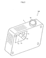
- Fig. 2 is a perspective view when the projector 100 is seen from beneath.
- the projector 100 is a single-plate type DLP (Digital Light Processing) projector. Inside of a body 1 of the projector 100, a light source unit 2 and an image projecting unit 3 are provided. Inside of the body 1, an air conditioning unit, a control unit, a power supply unit and the like, which are not shown, are provided as well.
- DLP Digital Light Processing
- the light source unit 2 is housed by a light source housing portion 1a provided in the body 1.
- a light source housing portion 1a provided in the body 1.
- an opening 1b communicatively connecting to the light source housing portion 1a is provided, as shown in Fig. 2.
- the light source unit 2 is placed in the light source housing portion 1a or taken out of the light source housing portion 1a through the opening 1b.
- the opening 1b is closed by a lid not shown at the time other than the placement and the removal of the light source unit 2.
- openings 1c, 1d are provided, respectively.
- Reference numerals 4, 5 of Fig. 1 denote a front and rear division-type case of the light source unit 2, being formed of metal having heat resistance and high strength, such as aluminum.
- Reference numeral 4 denotes a front case and reference numeral 5 denotes a rear case.
- Reference numeral 6 denotes a lamp which is a light source, and reference numeral 7 denotes a reflector that reflects and collects light of the lamp 6.
- the lamp 6 and the reflector 7 are arranged, and by fitting the rear case 5 and the front case 4 and fixing them by screws or the like, so that the front of the lamp 6 and the reflector 7 is covered with the front case 4, and the rear thereof is covered with the rear case 5, and the lamp 6 and the reflector 7 are held by the cases 4, 5.
- an opening 4a allowing the light emitted from the lamp 6 to exit is provided.
- Reference numeral 8 denotes a cover glass attached to an inside of the front case 4 so as to close the opening 4a.
- the cover glass 8 is a substantially square, plate-like glass that passes visible light rays and the like and does not pass ultraviolet, and removes the ultraviolet from the light emitted from the lamp 6 while transmitting the light.
- Reference numeral 9 denotes an insulating member attached to the inside of the front case 4.
- the insulating member 9 is formed of synthetic resin having an insulating property, impact absorbing property, heat resistance, and high strength such as liquid crystal polyester resin (LCP).
- LCP liquid crystal polyester resin
- an opening 9a allowing the light from the lamp 6 to exit is provided.
- the cover glass 8 is held by the front case 4 and the insulating member 9, as described later.
- Reference numeral 10 denotes a color wheel made of a disc in which red, green, blue color filters are disposed alternately in a circumferential direction.
- the color wheel 10 is rotated by a motor not shown, and transmits white light emitted from the lamp 6 through any one of the color filters to separate into red light, green light and blue light.
- Reference numeral 11 denotes a vertically-division-type case of the image projecting unit 3, which is formed of metal such as aluminum.
- an opening 11a allowing the light emitted from the lamp 6 and transmitting through the color wheel 10 to enter the inside is provided.
- the color wheel 10 is attached through an attaching member not shown. Inside of the case 11, parts for image projection 12 to 16 described below are attached.
- Reference numeral 12 denotes a light tunnel whose inner surface is mirrored.
- the light tunnel 12 allows the light entering from an opening on one end side thereof to be repeatedly reflected inside and to exit through an opening on another end, thereby changing the light into condensed uniform light with a short light path length.
- Reference numeral 13 denotes a mirror that reflects the light passing through the light tunnel 12.
- Reference numeral 14 denotes a relay lens that aligns a light flux of the light reflected in the mirror 13.
- Reference numeral 15 denotes a DMD (Digital Micromirror Device) in which several hundreds of thousand of minute micromirrors (whose illustration is omitted) are integrated on a semiconductor memory, and a pixel is composed of the individual micromirror to which a memory cell is assigned.
- DMD Digital Micromirror Device
- the DMD 15 is mounted on a circuit board not shown, and is cooled by a heat sink not shown.
- Each of the micromirrors of the DMD 15 is structured so as to be capable of tilting in two directions of ⁇ 12°, so that it is tilted in either of the directions by an electrostatic attraction in accordance with a memory value, and takes states of two values of ON/OFF by the tilting directions.
- Reference numeral 16 denotes a projection lens composed of an axially-telescopic cylinder, a plurality of lenses placed inside of the cylinder, and the like. The projection lens 16 transmits the light reflected in the DMD 15 to project it on a screen 20.
- the white light emitted from the lamp 6 passes through the opening 9a of the insulating member 9, and the ultraviolet is removed by the cover glass 8.
- the white light transmitting through the cover glass 8 passes through the opening 4a of the front case 4 and the opening 1c of the light source housing portion 1a, and transmits through any one of the color filters of the color wheel 10 to be separated into the red color, green color and blue color.
- the separated color light enters the inside through the opening 11a of the case 11, and passes through the light tunnel 12 to be condensed and uniformized.
- the light exiting the light tunnel 12 is reflected upward at a predetermined angle in the mirror 13, transmits through the relay lens 14, and is irradiated to the DMD 15.
- the projector 100 controls the operation state of the individual micromirror of the DMD 15 to turn ON/OFF, based on an inputted video signal or the like, thereby forming an image at the DMD 15 and projecting the image on the screen 20 through the projection lens 16.
- Fig. 3 is a perspective view showing an exploded state of the front case 4, the cover glass 8, the insulating member 9 of the light source unit 2.
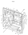
- Fig. 4 is a perspective view showing an attached state of the cover glass 8 and the insulating member 9 to the front case 4.
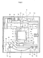
- Fig. 5 is a front view of the front case 4, showing a state seen from the insulating member 9 side in Fig. 3.
- Fig. 6 is a front view of the insulating member 9, showing a state seen from the front case 4 side in Fig. 3.
- an arrow represented by dot-dash line indicates an optical axis direction in which the light emitted from the lamp 6 advances.
- the above-described lamp 6, reflector 7 and rear case 5 are arranged, and on the tip end side (right obliquely upward in the figure), the above-described image projecting unit 3 is arranged.
- the inside of the front case 4 is recessed, and in the center of the inside, the opening 4a allowing the light of the above-described lamp 6 to exit is formed.
- a fitting portion 4b into which the cover glass 8 is fitted as shown in Fig. 3 and Fig.5 is formed around the opening 4a.
- the opening 4a is formed so as to be smaller than the cover glass 8.
- the fitting portion 4b is formed so as to be larger than the cover glass 8.
- projected portions 4c, 4d, 4e and recessed portions 4f, 4g, 4h are partially provided. As shown in Fig.
- an opening 4k larger than the opening 4a is formed.
- a supporting surface 4m that supports the insulating member 9 from beneath is formed.
- screw holes 4n into which screws 17 (one is shown in Fig. 4) for attaching the insulting member 9 are screwed are formed.
- bosses 4p into which the rear case 5 is fitted, and screw holes 4q into which screws not shown for joining the rear case 5 are screwed are formed.
- step portions 4r that support a tip end portion of the reflector 7 are formed.
- the insulating member 9 is attached to the inside of the front case 4 by the screws 17 as shown in Fig. 4, and insulates vicinities of the openings 4a, 4k and a portion from the openings 4a, 4k to the upper step portion 4r and the screw holes 4n inside of the front case 4 so that current does not flow.
- a portion from the openings 4a, 4k to the lower step portion 4r and a portion from the opening 4a to an inner surface opposite the opening 4k inside of the front case 4 are also insulated by attaching another insulating member not shown.
- the opening 9a allowing the light of the lamp 6 to exit is formed.
- a fitting portion 9b into which the cover glass 8 is fitted as shown in Fig. 6 is formed around the opening 9a on the front case 4 side.
- the opening 9a is formed so as to be smaller than the cover glass 8.
- the fitting portion 9b is formed so as to be larger than the cover glass 8.
- projected portions 9f, 9g, 9h and recessed portions 9c, 9d, 9e are partially provided.
- parts of the end surfaces 8d, 8e of the cover glass 8 are supported by the projected portions 9f, 9g, 9h.
- the projected portions 4c, 4d, 4e of the front case 4 are fitted into the recessed portions 9c, 9d, 9e of the insulating member 9, respectively, and the projected portions 9f, 9g, 9h of the insulating member 9 are fitted into the recessed portions 4f, 4g, 4h of the front case 4, respectively.
- the opening 4a of the front case 4 and the opening 9a of the insulating member 9 are communicatively connected.
- the openings 9a, 4a, and the opening 1c of the light source housing portion 1a are connected communicatively, so that the light of the lamp 6 enters the color wheel 10 through the openings 9a, 4a, 1a.
- an inclined wall 9j is formed as shown in Fig. 3 and the like. In a lower portion of the inclined wall 9j, an opening 9k smaller than the opening 4k of the front case 4 is formed.
- the inclined wall 9j of the insulating member 9 has a lower surface 9m supported by the supporting surface 4m of the front case 4 to substantially cover the opening 4k.
- the opening 9k of the insulating member 9 and the opening 4k of the front case 4 are communicatively connected. Furthermore, in the state where the light source unit 2 is incorporated into the body 1 as shown in Fig.
- the openings 9k, 4k and the opening 1d (Fig. 2) of the light source housing portion 1a are communicatively connected, and wind caused to flow by a fan set up in the body 1, which is not shown, passes through the openings 1d, 4k, 9k to cool the light source unit 2.
- a flange portion 9p is formed above the opening 9a of the insulating member 9. In the flange 9p, a through-hole 9n that the screw 17 for attaching the insulating member 9 to the front case 4 penetrates is formed.
- the fitting portion 9b of the insulating member 9 is brought close to the fitting portion 4b, and the respective projected portions 4c, 4d, 4e of the front case 4 and the projected portions 9f, 9g, 9h of the insulating member 9 are fitted into the recessed portions 9c, 9d, 9e and the recessed portions 4f, 4g, 4h thereof, respectively.
- the screws 17 are put through the trough-hole 9n of the insulating member 9 and are screwed into the screw holes 4n of the front case 4 to attach the insulating member 9 to the front case 4, as shown in Fig. 4.
- the cover glass 8 since only by performing the fitting of the cover grass 8 into the fitting portion 4b of the front case 4 and the attachment of the insulating member 9 to the front case 4, the cover glass 8 is fixed, working processes are decreased in number, labors are reduced, time is shortened, and a member only for fixing the cover glass 8 does not need to be prepared. Therefore, the cover glass 8 can be attached to the front case 4 of the light source unit 2 easily and with a low cost.
- the insulating member 9 formed of the synthetic resin can be manufactured with a cost lower than that of a member formed of sheet metal, which can further reduce the cost.
- the cover glass 8 is sandwiched and fixed by the front case 4 made of metal and the insulating member 9 made of synthetic resin having an impact absorbing property, heat resistance and high strength, even if an impact is applied to the light source unit 2, for example, by dropping the light source unit 2 taken out of the light source housing portion 1a of the body 1 by mistake when the lamp 6 is exchanged, the impact can be absorbed by the insulating member 9 to prevent the cover glass 8 from being easily broken or dropping off.
- the front case 4 and the insulating member 9 tolerate high heat when the lamp 6 emits light, which allows the fixed state of the cover glass 8 to be stably maintained.
- the inside of the front case 4 is insulated by the insulating member 9 or the like, even if the conductive member such as the electrode or the wire of the lamp 6 scatters forward at the time of damage of the lamp 6 such as burst, it does not come into contact with the front case 4, which can prevent a short circuit or electric leak from occurring.
- the portions of the end surfaces 8c, 8d, 8e of the cover glass 8 that are not supported by the projected portions 4c, 4d, 4e and the side wall 4j of the front case 4 can be grasped by the fingers or the like to fit the cover glass 8 into the fitting portion 4b without the fingers or the like touching the surfaces 8a, 8b of the cover glass 8 that transmit the light. Accordingly, deterioration in light transmitting performance and ultraviolet removing performance due to the contamination and scratching of the surfaces 8a, 8b can be prevented.
- the cover glass 8 can be stably supported by the front case 4 and the insulating member 9 at not only the surfaces 8a, 8b that transmit the light but the end surfaces 8c, 8d, 8e, 8j, which can more effectively prevent the breaking and damage of the cover glass 8.
- the portions of the end surfaces 8c, 8d, 8e of the cover glass 8 that are not supported by the projected portions 9f, 9g, 9h of the insulating member 9 may be grasped by the fingers or the like to fit the cover glass 8 into the fitting portion 9b of the insulating member 9, and in a state where the fitting portion 9b side of the insulating member 9 is upturned so that the cover glass 8 does not drop off from the fitting portion 9b, the insulating member 9 may be attached to the front case 4.
- the front case 4 is heavier than the insulating member 9, the procedure of attaching the insulating member 9 to the front case 4 in the state where the inside of the front case 4 is upturned is easier to attach the cover glass 4, and favorable in workability.
- the present invention is not limited only to this, but in addition to this, the present invention can also be applied to a case where an LED (Light Emitting Diode) is used as the light source.
- LED Light Emitting Diode
- the present invention is not limited only to this, but the cover glass attached to the front case may be glass having not only the ultraviolet removing function but a scatter preventing function of broken pieces of the lamp, such as tempered glass.
- the present invention is not limited only to this.
- the shape of the openings provided for light exit in the front case and the insulating member may be rectangular, circular or the like, and particularly the opening provided in the insulating member is not limited to a bore but may be a notch or the like.
- the shape of the cover glass is not limited to square, but may be rectangular, circular or the like.
- the present invention can be applied to a projection apparatus such as a three-plate type DLP projector using three DMDs as image forming parts and a liquid-crystal type projector using a liquid crystal panel, and a rear projection television, for example.
Landscapes
- Physics & Mathematics (AREA)
- General Physics & Mathematics (AREA)
- Engineering & Computer Science (AREA)
- Multimedia (AREA)
- Signal Processing (AREA)
- Projection Apparatus (AREA)
Abstract
Description
- The present invention relates to a projection apparatus that forms and projects an image by light emitted from a light source, and particularly to an attaching structure for a cover glass to a light source unit.
- Inside of a projection apparatus such as a projector and a rear projection television, there are provided a light source unit, an image projecting unit and the like. The light source unit is composed of a light source such as a lamp, a division-type case holding the light source, and the like. The image projecting unit is composed of an image forming device such as a DMD (Digital Micromirror Device), optical devices such as color wheel, lens and mirror, and a division-type case holding these devices, and the like. The respective cases are formed of metal so as to tolerate high heat when the light source emits light. When the light emitted from the light source exits through an opening of the case of the light source unit, and enters the case through an opening of the case of the image projecting unit, an image is formed based on the entering light and projected on a screen by the image forming device and the optical devices.
- Among the projection apparatuses, there is a projection apparatus in which in order to prevent ultraviolet contained in the light of the light source from deteriorating the above-described devices of the image projecting unit or from exerting a harmful influence on a human body, a cover glass that removes the ultraviolet from the light emitted from the light source while transmitting the light is attached to the opening of the case of the light source unit, as disclosed, for example, in
Patent Documents 1; Japanese Utility Model RegistrationNo. 3092509 Patent Document 2; Japanese Utility Model RegistrationNo. 3104472 Patent Documents 2 described above, openings allowing the light to exit are provided in a cover plate made of sheet metal for covering a front of the light source, which is attached to a frame of a front case, and a holding plate made of sheet metal for holding the cover glass, and both the plates are joined by screws or the like to sandwich and fix the cover glass by edges of both the openings. - Also, among the projection apparatuses, there is a projection apparatus in which in order to prevent devices around a lamp from being damaged when the lamp as a light source is burst, a cover glass for preventing burst pieces of the lamp from scrambling out of a light source unit is attached to an opening of a case of the light source unit, as disclosed in Patent Documents 3,
Japanese Patent Application Laid-Open No. 2004-239975 Patent Document 4,Japanese Patent Application Laid-Open No. 2005-149841 Patent Document 4,Japanese Patent Application Laid-Open No. 2005-149841 - In the structure as shown in the above-described
Patent Document 2, the cover glass is sandwiched and fixed between the cover plate and the holding plate made of metal, and thus, when the light source unit taken out of the projection apparatus, for example, at the time of the exchange of the light source such as the lamp drops by mistake or the like, and an impact is applied to the light source unit, there is a possibility that the impact is transmitted from both the plates, and that the cover glass is easily broken. Also, there is a possibility that at the time of damage of the light source such as burst of the lamp, a conductive member such as an electrode and a wire provided in the light source scatters forward, and comes into contact with the cover plate or the holding plate made of metal, resulting in a short circuit or electric leak. Moreover, since after the cover glass is sandwiched, and the cover plate and the holding plate are joined, the cover plate is joined to the frame of the front case to thereby attach the cover glass to the front case, the working process takes much effort and time. Furthermore, since the holding plate only for fixing the cover glass is formed of sheet metal and used, the cost is increased. - Moreover, in the above-described structure as shown in
Patent Document 4, the cover glass is inserted into the fitting portion provided in the opening of the explosion-proof cover made of the heat-resisting resin cylinder, and fixed with the heat-resisting adhesive or by the connecting portion and the spring member provided in the rod-shaped electrode of the lamp, and thus, there is a possibility that when an impact by dropping or the like is applied to the light source unit, the adhesion by the adhesive unsticks or the spring member is deformed and the connecting portion bumps, so that the cover glass easily drops off or is broken. Also, since the connecting portion and the spring member need to be provided in the rod-shaped electrode of the lamp or the like so as to contact the cover glass, a general-purpose light source cannot be used, resulting in much cost. - The present invention is made to solve the above-described problems, and an object of the present invention is to provide a projection apparatus in which a cover glass can be attached to a light source unit easily and with a low cost, and breaking or dropping-off of the cover glass when an impact is applied, and a short circuit or electric leak when a light source is damaged can be prevented.
- According to the present invention, in a projection apparatus which comprises a light source unit having a light source, a cover glass that transmits light emitted from the light source, and a division-type case that holds the light source and the cover glass, and forms and projects an image by the light exiting the light source unit, the projection apparatus comprises a front case made of metal that covers a front of the light source and is one component of the case, and an insulating member having an insulating property, impact absorbing property, and heat resistance that is attached to an inside of the front case, wherein openings allowing the light emitted from the light source to exit are provided in the front case and the insulating member, respectively, so as to be communicatively connected, and fitting portions into which the cover glass is fitted are provided around the openings, and the cover glass is fitted into one of the fitting portions to attach the insulating member to the front case, by which the cover glass is sandwiched and fixed by the front case and the insulating member.
- With this constitution, since only by performing the fitting of the cover glass into one of the fitting portions of the front case and the insulating member and the attachment of the insulating member to the front case, the cover glass is fixed, working processes are decreased in number, labors are reduced, time is shortened, and a member only for fixing the cover glass does not need to be prepared. Therefore, the cover glass can be attached to the front case of the light source unit easily and with a low cost. Moreover, since the cover glass is sandwiched and fixed by the front case made of metal and the insulating member having the impact absorbing property and heat resistance, the impact is absorbed by the insulating member when the impact is applied to the light source unit, so that the cover glass can be prevented from being easily broken or dropping off. Additionally, the front case and the insulating member tolerate high heat when the light source emits light, which allows the fixed state of the cover glass to be stably maintained. Furthermore, since the inside of the front case is insulated by the insulating member, even if a conductive member provided in the light source scatters forward when the light source is damaged, it does not come into contact with the front case, which can prevent a short circuit or electric leak from occurring.
- Moreover, according to the present invention, in each of the fitting portions of the front case and the insulating member, projected portions that support parts of end surfaces of the cover glass and recessed portions into which the projected portions of the counterpart are fitted are partially provided.
- In the structure where entire end surfaces of the cover glass are supported by side walls of the fitting portion of the explosion-proof cover as in the above-described
Patent Document 4, there is a possibility that fingers or the like touch the surfaces of the cover glass that transmit the light, thereby contaminating or scratching the surfaces when the cover glass is fitted into the fitting portions, so that light transmitting performance is deteriorated. However, in the case where the projected portions and the recessed portions are partially provided in the fitting portions of the front case and the insulating portion as described above, the portions of the end surfaces of the cover glass that are not supported by the projected portions of the front case can be grasped by the fingers to fit the cover glass into the fitting portion without the fingers or the like touching the surfaces of the cover glass that transmit the light. Accordingly, deterioration in light transmitting performance due to the contamination and scratching of the surfaces of the cover glass that transmit the light can be prevented. Moreover, the projected portions of the front case and the insulating member are fitted into the respective recessed portions thereof, respectively, so that wobbling of the insulating member can be suppressed, and the insulating member can be easily attached to the front case. Furthermore, the cover glass can be stably supported by the front case and the insulated member at not only the surfaces that transmit the light but the end surfaces, which can more effectively prevent the breaking and damage of the cover glass. - Furthermore, according to a typical embodiment of the present invention, in a projection apparatus which comprises a light source unit having a lamp, a plate-like cover glass that removes ultraviolet from light emitted from the lamp while transmitting the light, and a division-type case that holds the lamp and the cover glass, and forms and projects an image by the light exiting the light source unit, the projection apparatus comprises a front case made of metal that covers a front of the lamp and is one component of the case, and an insulating member made of synthetic resin having an insulating property, impact absorbing property, heat resistance, and high strength that is attached to an inside of the front case, wherein openings allowing the light emitted from the lamp to exit are provided in the front case and the insulating member, respectively, so as to be communicatively connected, and fitting portions into which the cover glass is fitted are provided around the openings, and in each of the fitting portions, a plurality of projected portions that support parts of end surfaces of the cover glass, and a plurality of recessed portions into which the projected portions of the counterpart are fitted are partially provided, and the cover glass is fitted into the fitting portion of the front case, and the respective projected portions of the front case and the insulating member are fitted into the respective recessed portions thereof to attach the insulating member to the front case, by which the cover glass is supported by the projected portions and is sandwiched and fixed by the front case and the insulating member.
- With this constitution, since only by performing the fitting of the cover glass having the ultraviolet removing function into the fitting portion of the front case and the attachment of the insulating member to the front case, the cover glass is fixed, working processes are decreased in number, labors are reduced, time is shortened, and a member only for fixing the cover glass does not need to be prepared. Therefore, the cover glass can be attached to the front case of the light source unit easily and with a low cost. Particularly, since the insulating member formed of synthetic resin can be manufactured with a cost lower than that of the member formed of sheet metal, the cost can be further reduced. Moreover, since the cover glass is sandwiched and fixed by the front case made of metal and the insulating member made of synthetic resin having the impact absorbing property and heat resistance and high strength, the impact is absorbed by the insulating member when the impact is applied to the light source unit, so that the cover glass can be prevented from being easily broken or dropping off. Additionally, the front case and the insulating member tolerate high heat when the lamp emits light, which allows the fixed state of the cover glass to be stably maintained. Furthermore, since the inside of the front case is insulated by the insulating member, even if a conductive member such as an electrode and a wire of the lamp scatters forward at the time of damage of the lamp such as burst, it does not come into contact with the front case, which can prevent a short circuit or electric leak from occurring. Furthermore, since the projected portions and the recessed portions are partially provided in the fitting portions of the front case and the insulating portion, the portions of the end surfaces of the cover glass that are not supported by the projected portions of the front case can be grasped by the fingers or the like to fit the cover glass into the fitting portion without the fingers or the like touching the surfaces of the cover glass that transmit the light. Accordingly, deterioration in light transmitting performance and ultraviolet removing performance due to the contamination and scratching of the surfaces of the cover glass that transmit the light can be prevented. Additionally, the projected portions of the front case and the insulating member are fitted into the respective recessed portions thereof, respectively, so that wobbling of the insulating member can be suppressed, and the insulating member can be easily attached to the front case. Furthermore, the cover glass can be stably supported by the front case and the insulated member at not only the surfaces that transmit the light but the end surfaces, which can more effectively prevent the breaking and damage of the cover glass.
- According to the present invention, since the cover glass is sandwiched and fixed by the front case made of metal and the insulating member having the impact absorbing property and heat resistance, the cover glass can be attached to the light source unit easily and with a low cost. Also, the cover glass can be prevented from being easily broken or dropping off when an impact is applied to the light source unit, and the conductive member of the light source and the front case are insulated by the insulating member, which can prevent a short circuit or electric leak from occurring when the light source is damaged.
-
- Fig. 1 is a structure diagram of a projector which is one example of a projection apparatus according to the present invention;
- Fig. 2 is a perspective view when the projector is seen from beneath;
- Fig. 3 is an exploded state view of a front case, a cover glass and an insulating member included in a light source unit of the projector;
- Fig. 4 is an attached state view of the front case, the cover glass and the insulating member;
- Fig. 5 is a front view of the front case; and
- Fig. 6 is a front view of the insulating member.
- Hereinafter, referring to the drawings, embodiments of the present invention are described. Fig. 1 is a diagram showing a schematic structure of a
projector 100, which is one example of a projection apparatus according to the present invention. Fig. 2 is a perspective view when theprojector 100 is seen from beneath. Theprojector 100 is a single-plate type DLP (Digital Light Processing) projector. Inside of abody 1 of theprojector 100, alight source unit 2 and an image projecting unit 3 are provided. Inside of thebody 1, an air conditioning unit, a control unit, a power supply unit and the like, which are not shown, are provided as well. - The
light source unit 2 is housed by a light source housing portion 1a provided in thebody 1. In a bottom portion of thebody 1, an opening 1b communicatively connecting to the light source housing portion 1a is provided, as shown in Fig. 2. Thelight source unit 2 is placed in the light source housing portion 1a or taken out of the light source housing portion 1a through the opening 1b. The opening 1b is closed by a lid not shown at the time other than the placement and the removal of thelight source unit 2. In front of the light source housing portion 1a (image projecting unit 3 side),openings 1c, 1d are provided, respectively. -
Reference numerals light source unit 2, being formed of metal having heat resistance and high strength, such as aluminum.Reference numeral 4 denotes a front case andreference numeral 5 denotes a rear case.Reference numeral 6 denotes a lamp which is a light source, andreference numeral 7 denotes a reflector that reflects and collects light of thelamp 6. Inside of therear case 5, thelamp 6 and thereflector 7 are arranged, and by fitting therear case 5 and thefront case 4 and fixing them by screws or the like, so that the front of thelamp 6 and thereflector 7 is covered with thefront case 4, and the rear thereof is covered with therear case 5, and thelamp 6 and thereflector 7 are held by thecases front case 4, anopening 4a allowing the light emitted from thelamp 6 to exit is provided.Reference numeral 8 denotes a cover glass attached to an inside of thefront case 4 so as to close theopening 4a. Thecover glass 8 is a substantially square, plate-like glass that passes visible light rays and the like and does not pass ultraviolet, and removes the ultraviolet from the light emitted from thelamp 6 while transmitting the light.Reference numeral 9 denotes an insulating member attached to the inside of thefront case 4. The insulatingmember 9 is formed of synthetic resin having an insulating property, impact absorbing property, heat resistance, and high strength such as liquid crystal polyester resin (LCP). In the insulatingmember 9, anopening 9a allowing the light from thelamp 6 to exit is provided. Thecover glass 8 is held by thefront case 4 and the insulatingmember 9, as described later. -
Reference numeral 10 denotes a color wheel made of a disc in which red, green, blue color filters are disposed alternately in a circumferential direction. Thecolor wheel 10 is rotated by a motor not shown, and transmits white light emitted from thelamp 6 through any one of the color filters to separate into red light, green light and blue light.Reference numeral 11 denotes a vertically-division-type case of the image projecting unit 3, which is formed of metal such as aluminum. In a side surface on thelight source unit 2 side of thecase 11, an opening 11a allowing the light emitted from thelamp 6 and transmitting through thecolor wheel 10 to enter the inside is provided. Also, in the side surface of thecase 11, thecolor wheel 10 is attached through an attaching member not shown. Inside of thecase 11, parts forimage projection 12 to 16 described below are attached. -
Reference numeral 12 denotes a light tunnel whose inner surface is mirrored. Thelight tunnel 12 allows the light entering from an opening on one end side thereof to be repeatedly reflected inside and to exit through an opening on another end, thereby changing the light into condensed uniform light with a short light path length.Reference numeral 13 denotes a mirror that reflects the light passing through thelight tunnel 12.Reference numeral 14 denotes a relay lens that aligns a light flux of the light reflected in themirror 13.Reference numeral 15 denotes a DMD (Digital Micromirror Device) in which several hundreds of thousand of minute micromirrors (whose illustration is omitted) are integrated on a semiconductor memory, and a pixel is composed of the individual micromirror to which a memory cell is assigned. TheDMD 15 is mounted on a circuit board not shown, and is cooled by a heat sink not shown. Each of the micromirrors of theDMD 15 is structured so as to be capable of tilting in two directions of ±12°, so that it is tilted in either of the directions by an electrostatic attraction in accordance with a memory value, and takes states of two values of ON/OFF by the tilting directions.Reference numeral 16 denotes a projection lens composed of an axially-telescopic cylinder, a plurality of lenses placed inside of the cylinder, and the like. Theprojection lens 16 transmits the light reflected in theDMD 15 to project it on ascreen 20. - As indicated by arrow, the white light emitted from the
lamp 6 passes through theopening 9a of the insulatingmember 9, and the ultraviolet is removed by thecover glass 8. The white light transmitting through thecover glass 8 passes through theopening 4a of thefront case 4 and the opening 1c of the light source housing portion 1a, and transmits through any one of the color filters of thecolor wheel 10 to be separated into the red color, green color and blue color. The separated color light enters the inside through the opening 11a of thecase 11, and passes through thelight tunnel 12 to be condensed and uniformized. The light exiting thelight tunnel 12 is reflected upward at a predetermined angle in themirror 13, transmits through therelay lens 14, and is irradiated to theDMD 15. At this time, when the micromirror of theDMD 15 is in an ON state, the light reflected in the mirror is taken in by theprojection lens 16 to be projected on thescreen 20. When the micromirror is in an OFF state, the light reflected in the mirror is not taken in by theprojection lens 16, so that it is not projected on thescreen 20. That is, theprojector 100 controls the operation state of the individual micromirror of theDMD 15 to turn ON/OFF, based on an inputted video signal or the like, thereby forming an image at theDMD 15 and projecting the image on thescreen 20 through theprojection lens 16. - Fig. 3 is a perspective view showing an exploded state of the
front case 4, thecover glass 8, the insulatingmember 9 of thelight source unit 2. Fig. 4 is a perspective view showing an attached state of thecover glass 8 and the insulatingmember 9 to thefront case 4. Fig. 5 is a front view of thefront case 4, showing a state seen from the insulatingmember 9 side in Fig. 3. Fig. 6 is a front view of the insulatingmember 9, showing a state seen from thefront case 4 side in Fig. 3. In Fig. 3 and Fig 4, an arrow represented by dot-dash line indicates an optical axis direction in which the light emitted from thelamp 6 advances. On the rear end side of the arrow (left obliquely downward in the figure), the above-describedlamp 6,reflector 7 andrear case 5 are arranged, and on the tip end side (right obliquely upward in the figure), the above-described image projecting unit 3 is arranged. - The inside of the
front case 4 is recessed, and in the center of the inside, theopening 4a allowing the light of the above-describedlamp 6 to exit is formed. Afitting portion 4b into which thecover glass 8 is fitted as shown in Fig. 3 and Fig.5 is formed around theopening 4a. Theopening 4a is formed so as to be smaller than thecover glass 8. Thefitting portion 4b is formed so as to be larger than thecover glass 8. In thefitting portion 4b, projectedportions portions cover glass 8 is fitted into thefitting portion 4b, parts of end surfaces 8c, 8d, 8e perpendicular tosurfaces 8a, 8b of thecover glass 8 that transmit the light (8b is a surface on the opposite side of 8a, and shown in Fig. 6) are supported by the projectedportions cover glass 8 is supported by a side wall 4j of thefitting portion 4b. - At the side of the
opening 4a of thefront case 4, anopening 4k larger than theopening 4a is formed. In a lower end portion of theopening 4k, a supportingsurface 4m that supports the insulatingmember 9 from beneath is formed. In an upper portion of theopening 4k and in an upper right portion of theopening 4a,screw holes 4n into which screws 17 (one is shown in Fig. 4) for attaching theinsulting member 9 are screwed are formed. In an upper and lower end portions of thefront case 4,bosses 4p into which therear case 5 is fitted, and screwholes 4q into which screws not shown for joining therear case 5 are screwed are formed. In the vicinity of thebosses 4p and thescrew holes 4q,step portions 4r that support a tip end portion of thereflector 7 are formed. - The insulating
member 9 is attached to the inside of thefront case 4 by thescrews 17 as shown in Fig. 4, and insulates vicinities of theopenings openings upper step portion 4r and thescrew holes 4n inside of thefront case 4 so that current does not flow. A portion from theopenings lower step portion 4r and a portion from theopening 4a to an inner surface opposite theopening 4k inside of thefront case 4 are also insulated by attaching another insulating member not shown. In this manner, in the case where the inside of thefront case 4 is insulted by the insulatingmember 9 or the like, even if thelamp 6 is burst in the state where thelight source unit 2 is assembled and incorporated into thebody 1 as shown in Fig. 1, and a conductive member such as an electrode and a wire provided in thelamp 6, which are not shown, scatters forward from thereflector 7, the conductive member does not come into contact with thefront case 4. - As shown in Fig. 3, in a front portion of the insulating
member 9, theopening 9a allowing the light of thelamp 6 to exit is formed. Afitting portion 9b into which thecover glass 8 is fitted as shown in Fig. 6 is formed around theopening 9a on thefront case 4 side. Theopening 9a is formed so as to be smaller than thecover glass 8. Thefitting portion 9b is formed so as to be larger than thecover glass 8. In thefitting portion 9b, projectedportions portions cover glass 8 is fitted into thefitting portion 9b as shown in Fig. 6, parts of the end surfaces 8d, 8e of thecover glass 8 are supported by the projectedportions member 9 is attached to thefront case 4 as shown in Fig. 4, the projectedportions front case 4 are fitted into the recessedportions member 9, respectively, and the projectedportions member 9 are fitted into the recessedportions front case 4, respectively. Moreover, theopening 4a of thefront case 4 and theopening 9a of the insulatingmember 9 are communicatively connected. Furthermore, in the state where thelight source unit 2 is incorporated into thebody 1 as shown in Fig. 1, theopenings lamp 6 enters thecolor wheel 10 through theopenings - At the side of the
opening 9a of the insulatingmember 9, an inclined wall 9j is formed as shown in Fig. 3 and the like. In a lower portion of the inclined wall 9j, anopening 9k smaller than theopening 4k of thefront case 4 is formed. In the state where the insulatingmember 9 is attached to thefront case 4 as shown in Fig. 4, the inclined wall 9j of the insulatingmember 9 has alower surface 9m supported by the supportingsurface 4m of thefront case 4 to substantially cover theopening 4k. Moreover, theopening 9k of the insulatingmember 9 and theopening 4k of thefront case 4 are communicatively connected. Furthermore, in the state where thelight source unit 2 is incorporated into thebody 1 as shown in Fig. 1, theopenings opening 1d (Fig. 2) of the light source housing portion 1a are communicatively connected, and wind caused to flow by a fan set up in thebody 1, which is not shown, passes through theopenings light source unit 2. Aflange portion 9p is formed above theopening 9a of the insulatingmember 9. In theflange 9p, a through-hole 9n that thescrew 17 for attaching the insulatingmember 9 to thefront case 4 penetrates is formed. - In the above-described constitution, in order to attach the
cover glass 8 and the insulatingmember 9 to thefront case 4, first, the portions of the end surfaces 8c, 8d, 8e of thecover glass 8 that are not supported by the projectedportions front case 4 are grasped by fingers or the like, and thecover glass 8 is fitted into thefitting portion 4b of thefront case 4 as shown in Fig. 5. Next, in a state where the inside of thefront case 4 is upturned so that thecover glass 8 does not drop off from thefitting portion 4b, thefitting portion 9b of the insulatingmember 9 is brought close to thefitting portion 4b, and the respective projectedportions front case 4 and the projectedportions member 9 are fitted into the recessedportions portions screws 17 are put through the trough-hole 9n of the insulatingmember 9 and are screwed into the screw holes 4n of thefront case 4 to attach the insulatingmember 9 to thefront case 4, as shown in Fig. 4. This allows the respective end surfaces 8c, 8d, 8e, 8j of thecover glass 8 to be supported by the respective projectedportions front case 4 and theinsulting member 9, and the side wall 4j of thefront case 4, and both thesurfaces 8a, 8b of thecover glass 8 that transmit the light are sandwiched by thefitting portions front case 4 and the insulatingmember 9 to fix thecover glass 8. - In this manner, since only by performing the fitting of the
cover grass 8 into thefitting portion 4b of thefront case 4 and the attachment of the insulatingmember 9 to thefront case 4, thecover glass 8 is fixed, working processes are decreased in number, labors are reduced, time is shortened, and a member only for fixing thecover glass 8 does not need to be prepared. Therefore, thecover glass 8 can be attached to thefront case 4 of thelight source unit 2 easily and with a low cost. Particularly, the insulatingmember 9 formed of the synthetic resin can be manufactured with a cost lower than that of a member formed of sheet metal, which can further reduce the cost. - Moreover, since the
cover glass 8 is sandwiched and fixed by thefront case 4 made of metal and the insulatingmember 9 made of synthetic resin having an impact absorbing property, heat resistance and high strength, even if an impact is applied to thelight source unit 2, for example, by dropping thelight source unit 2 taken out of the light source housing portion 1a of thebody 1 by mistake when thelamp 6 is exchanged, the impact can be absorbed by the insulatingmember 9 to prevent thecover glass 8 from being easily broken or dropping off. Additionally, thefront case 4 and the insulatingmember 9 tolerate high heat when thelamp 6 emits light, which allows the fixed state of thecover glass 8 to be stably maintained. Furthermore, since the inside of thefront case 4 is insulated by the insulatingmember 9 or the like, even if the conductive member such as the electrode or the wire of thelamp 6 scatters forward at the time of damage of thelamp 6 such as burst, it does not come into contact with thefront case 4, which can prevent a short circuit or electric leak from occurring. - Moreover, in the structure where the entire end surfaces of the cover glass are supported by the side walls of the fitting portion of the explosion-proof cover as in the
aforementioned Patent Document 4, fingers or the like touch the surfaces of the cover glass that transmit the light when the cover glass is fitted into the fitting portion, thereby contaminating or scratching the surface, so that light transmitting performance and ultraviolet removing performance are deteriorated. However, in the case where the projectedportions portions fitting portion 4b of thefront case 4 as described above, the portions of the end surfaces 8c, 8d, 8e of thecover glass 8 that are not supported by the projectedportions front case 4 can be grasped by the fingers or the like to fit thecover glass 8 into thefitting portion 4b without the fingers or the like touching thesurfaces 8a, 8b of thecover glass 8 that transmit the light. Accordingly, deterioration in light transmitting performance and ultraviolet removing performance due to the contamination and scratching of thesurfaces 8a, 8b can be prevented. Moreover, since the projectedportions portions fitting portion 9b of the insulatingmember 9, the respective projected portions of thefront case 4 and the insulatingmember 9 are fitted into the respective recessed portions thereof, so that wobbling of the insulatingmember 9 can be suppressed, and the insulatingmember 9 can be easily attached to thefront case 4 by thescrews 17. Furthermore, thecover glass 8 can be stably supported by thefront case 4 and the insulatingmember 9 at not only thesurfaces 8a, 8b that transmit the light but the end surfaces 8c, 8d, 8e, 8j, which can more effectively prevent the breaking and damage of thecover glass 8. - In the present invention, various forms other than the above-described embodiment can be employed. For example, while in the above-described embodiment, the example in which the
cover glass 8 is fitted into thefitting portion 4b of thefront case 4 to attach the insulatingmember 9 to thefront case 4 is taken, the present invention is not limited only to this. In addition to this, the portions of the end surfaces 8c, 8d, 8e of thecover glass 8 that are not supported by the projectedportions member 9 may be grasped by the fingers or the like to fit thecover glass 8 into thefitting portion 9b of the insulatingmember 9, and in a state where thefitting portion 9b side of the insulatingmember 9 is upturned so that thecover glass 8 does not drop off from thefitting portion 9b, the insulatingmember 9 may be attached to thefront case 4. However, since thefront case 4 is heavier than the insulatingmember 9, the procedure of attaching the insulatingmember 9 to thefront case 4 in the state where the inside of thefront case 4 is upturned is easier to attach thecover glass 4, and favorable in workability. - Moreover, while in the above-described embodiment, the example in which the
lamp 6 is used as the light source is taken, the present invention is not limited only to this, but in addition to this, the present invention can also be applied to a case where an LED (Light Emitting Diode) is used as the light source. - Moreover, while in the above-described embodiment, the example in which the
cover glass 8 having the ultraviolet removing function is attached to thefront case 4 is taken, the present invention is not limited only to this, but the cover glass attached to the front case may be glass having not only the ultraviolet removing function but a scatter preventing function of broken pieces of the lamp, such as tempered glass. - Furthermore, while in the above-described embodiment, the example in which the substantially square, bore-shaped
openings front case 4 and the insulatingmember 9 to set up the substantiallysquare cover glass 8 between theopenings - Still further, while in the above-described embodiment, the example in which the present invention is applied to the single-plate
type DLP projector 100 is taken, in addition to this, the present invention can be applied to a projection apparatus such as a three-plate type DLP projector using three DMDs as image forming parts and a liquid-crystal type projector using a liquid crystal panel, and a rear projection television, for example.
Claims (3)
- A projection apparatus which comprises a light source unit having a lamp, a plate-like cover glass that removes ultraviolet from light emitted from the lamp while transmitting said light, and a division-type case that holds the lamp and the cover glass, and forms and projects an image by the light exiting the light source unit, comprising:a front case made of metal that covers a front of said lamp and is one component of said case; andan insulating member made of synthetic resin having an insulating property, impact absorbing property, heat resistance, and high strength that is attached to an inside of said front case,wherein openings allowing the light emitted from the lamp to exit are provided in said front case and said insulating member, respectively, so as to be communicatively connected, and fitting portions into which said cover glass is fitted are provided around the openings, and in each of the fitting portions, a plurality of projected portions that support parts of end surfaces of said cover glass, and a plurality of recessed portions into which the projected portions of the counterpart are fitted are partially provided; and
said cover glass is fitted into said fitting portion of said front case, and said respective projected portions of said front case and said insulating member are fitted into said respective recessed portions thereof to attach the insulating member to the front case, by which the cover glass is supported by the respective projected portions and is sandwiched and fixed by the front case and the insulating member. - A projection apparatus which comprises a light source unit having a light source, a cover glass that transmits light emitted from the light source, and a division-type case that holds the light source and the cover glass, and forms and projects an image by the light exiting the light source unit, comprising:a front case made of metal that covers a front of said light source and is one component of said case; andan insulating member having an insulating property, impact absorbing property, and heat resistance that is attached to an inside of said front case,wherein openings allowing the light emitted from the light source to exit are provided in said front case and said insulating member, respectively, so as to be communicatively connected, and fitting portions into which said cover glass is fitted are provided around the openings; and
said cover glass is fitted into one of the fitting portions to attach said insulating member to said front case, by which the cover glass is sandwiched and fixed by the front case and the insulating member. - The projection apparatus according to claim 2,
wherein in each of the fitting portions of said front case and said insulating member, projected portions that support parts of end surfaces of said cover glass and recessed portions into which the projected portions of the counterpart are fitted are partially provided.
Priority Applications (1)
| Application Number | Priority Date | Filing Date | Title |
|---|---|---|---|
| PL07005204T PL1838098T3 (en) | 2006-03-15 | 2007-03-13 | Projection apparatus |
Applications Claiming Priority (1)
| Application Number | Priority Date | Filing Date | Title |
|---|---|---|---|
| JP2006071224A JP2007248753A (en) | 2006-03-15 | 2006-03-15 | Projection device |
Publications (2)
| Publication Number | Publication Date |
|---|---|
| EP1838098A1 true EP1838098A1 (en) | 2007-09-26 |
| EP1838098B1 EP1838098B1 (en) | 2008-11-12 |
Family
ID=38068542
Family Applications (1)
| Application Number | Title | Priority Date | Filing Date |
|---|---|---|---|
| EP07005204A Not-in-force EP1838098B1 (en) | 2006-03-15 | 2007-03-13 | Projection apparatus |
Country Status (6)
| Country | Link |
|---|---|
| US (1) | US7819535B2 (en) |
| EP (1) | EP1838098B1 (en) |
| JP (1) | JP2007248753A (en) |
| CN (1) | CN101038429A (en) |
| DE (1) | DE602007000237D1 (en) |
| PL (1) | PL1838098T3 (en) |
Families Citing this family (8)
| Publication number | Priority date | Publication date | Assignee | Title |
|---|---|---|---|---|
| JP2006058859A (en) * | 2004-07-23 | 2006-03-02 | Kazuji Yoshida | Image display apparatus |
| JP4229087B2 (en) * | 2005-05-26 | 2009-02-25 | ソニー株式会社 | Projection display |
| JP2015108657A (en) * | 2013-12-03 | 2015-06-11 | 株式会社リコー | Image projection device and discharge lamp |
| CN106444239A (en) * | 2015-08-04 | 2017-02-22 | 杨毅 | Illuminating device, lighting fitting, projection display device |
| CN105068368B (en) * | 2015-08-27 | 2017-08-29 | 杨毅 | Light-emitting device, projection display equipment and light fixture |
| CN106597792B (en) * | 2015-10-15 | 2018-06-29 | 青岛海高设计制造有限公司 | Display device and air conditioner |
| CN105159016A (en) * | 2015-10-30 | 2015-12-16 | 广西中才铝业有限公司 | Projector shell |
| CN109884852A (en) * | 2019-03-29 | 2019-06-14 | 苏州佳世达光电有限公司 | Light source module and projection arrangement |
Citations (7)
| Publication number | Priority date | Publication date | Assignee | Title |
|---|---|---|---|---|
| JPH11237691A (en) * | 1998-02-24 | 1999-08-31 | Mitsubishi Electric Corp | Lamp box and projector device |
| US20020039174A1 (en) * | 2000-09-29 | 2002-04-04 | Seiko Epson Corporation | Light source and projector |
| JP2004239975A (en) * | 2003-02-03 | 2004-08-26 | Tamron Co Ltd | Lamp holder |
| US20040228130A1 (en) * | 2003-02-25 | 2004-11-18 | Seiko Epson Corporation | Light source and projector |
| JP2005149841A (en) * | 2003-11-13 | 2005-06-09 | Casio Comput Co Ltd | Light source device |
| EP1542460A1 (en) * | 2003-12-09 | 2005-06-15 | Casio Computer Co., Ltd. | Light source device and projector apparatus |
| JP2005196230A (en) * | 1999-10-15 | 2005-07-21 | Sony Corp | Projection display |
Family Cites Families (10)
| Publication number | Priority date | Publication date | Assignee | Title |
|---|---|---|---|---|
| JPH0392509U (en) | 1990-01-10 | 1991-09-20 | ||
| JPH03104472U (en) | 1990-02-14 | 1991-10-30 | ||
| JP3104472B2 (en) | 1993-06-15 | 2000-10-30 | 関東特殊製鋼株式会社 | Roll material for hot rolling |
| JP3092509B2 (en) | 1996-03-26 | 2000-09-25 | 住友電装株式会社 | Flattening method and apparatus for cable |
| JP3092509U (en) * | 2002-09-02 | 2003-03-20 | 船井電機株式会社 | Image display projector using DMD |
| US7358657B2 (en) * | 2004-01-30 | 2008-04-15 | Hewlett-Packard Development Company, L.P. | Lamp assembly |
| JP3104472U (en) * | 2004-04-06 | 2004-09-16 | 船井電機株式会社 | Image display projector |
| JP4093211B2 (en) * | 2004-07-14 | 2008-06-04 | セイコーエプソン株式会社 | Light source device and projector |
| JP4502885B2 (en) * | 2005-06-01 | 2010-07-14 | 三洋電機株式会社 | Projection display |
| JP4848703B2 (en) * | 2005-08-16 | 2011-12-28 | ソニー株式会社 | Heat dissipation structure in video projector |
-
2006
- 2006-03-15 JP JP2006071224A patent/JP2007248753A/en active Pending
-
2007
- 2007-03-12 US US11/716,969 patent/US7819535B2/en not_active Expired - Fee Related
- 2007-03-13 DE DE602007000237T patent/DE602007000237D1/en active Active
- 2007-03-13 EP EP07005204A patent/EP1838098B1/en not_active Not-in-force
- 2007-03-13 PL PL07005204T patent/PL1838098T3/en unknown
- 2007-03-15 CN CNA2007100881339A patent/CN101038429A/en active Pending
Patent Citations (7)
| Publication number | Priority date | Publication date | Assignee | Title |
|---|---|---|---|---|
| JPH11237691A (en) * | 1998-02-24 | 1999-08-31 | Mitsubishi Electric Corp | Lamp box and projector device |
| JP2005196230A (en) * | 1999-10-15 | 2005-07-21 | Sony Corp | Projection display |
| US20020039174A1 (en) * | 2000-09-29 | 2002-04-04 | Seiko Epson Corporation | Light source and projector |
| JP2004239975A (en) * | 2003-02-03 | 2004-08-26 | Tamron Co Ltd | Lamp holder |
| US20040228130A1 (en) * | 2003-02-25 | 2004-11-18 | Seiko Epson Corporation | Light source and projector |
| JP2005149841A (en) * | 2003-11-13 | 2005-06-09 | Casio Comput Co Ltd | Light source device |
| EP1542460A1 (en) * | 2003-12-09 | 2005-06-15 | Casio Computer Co., Ltd. | Light source device and projector apparatus |
Also Published As
| Publication number | Publication date |
|---|---|
| PL1838098T3 (en) | 2009-04-30 |
| US7819535B2 (en) | 2010-10-26 |
| CN101038429A (en) | 2007-09-19 |
| JP2007248753A (en) | 2007-09-27 |
| US20070216873A1 (en) | 2007-09-20 |
| EP1838098B1 (en) | 2008-11-12 |
| DE602007000237D1 (en) | 2008-12-24 |
Similar Documents
| Publication | Publication Date | Title |
|---|---|---|
| EP1838098B1 (en) | Projection apparatus | |
| US6840633B2 (en) | Lamp reflector assembly | |
| US6834964B2 (en) | Liquid crystal projector | |
| US20030071975A1 (en) | Optical device and projector | |
| US8882277B2 (en) | Image projection apparatus | |
| CN101114111B (en) | Optical system unit and projector | |
| WO2004036308A1 (en) | Lighting equipment, exhaust unit, and projector with the equipment and exhaust unit | |
| US7384155B2 (en) | Image display | |
| JP4079048B2 (en) | Optical device and projector | |
| JP6731142B2 (en) | Light source device, projection device, and substrate mounting method for light source device | |
| JP6777092B2 (en) | Projection type display device | |
| CN108427239A (en) | Light supply apparatus and projection arrangement | |
| JP3988499B2 (en) | Illumination optical device, projector and light source device | |
| US20120154758A1 (en) | Projection display device | |
| JP7004196B2 (en) | Electronic equipment, light source equipment and projection equipment | |
| CN101135834B (en) | Projected video display device | |
| CN107966873B (en) | Light source device and projector | |
| JP2000221598A (en) | Projection display device | |
| JP2004085943A (en) | Optical device, optical unit and projector provided with the optical device | |
| JP2008170854A (en) | projector | |
| JP2004170512A (en) | Optical device, optical unit, and projector | |
| JP2000241880A (en) | Optical device | |
| JP2001066698A (en) | Projection display device | |
| US9606426B2 (en) | Duct cover for an image projection apparatus | |
| JP4055420B2 (en) | Light source device and projector provided with the light source device |
Legal Events
| Date | Code | Title | Description |
|---|---|---|---|
| PUAI | Public reference made under article 153(3) epc to a published international application that has entered the european phase |
Free format text: ORIGINAL CODE: 0009012 |
|
| AK | Designated contracting states |
Kind code of ref document: A1 Designated state(s): AT BE BG CH CY CZ DE DK EE ES FI FR GB GR HU IE IS IT LI LT LU LV MC MT NL PL PT RO SE SI SK TR |
|
| AX | Request for extension of the european patent |
Extension state: AL BA HR MK YU |
|
| 17P | Request for examination filed |
Effective date: 20071122 |
|
| 17Q | First examination report despatched |
Effective date: 20071227 |
|
| GRAP | Despatch of communication of intention to grant a patent |
Free format text: ORIGINAL CODE: EPIDOSNIGR1 |
|
| AKX | Designation fees paid |
Designated state(s): DE FR GB PL |
|
| GRAS | Grant fee paid |
Free format text: ORIGINAL CODE: EPIDOSNIGR3 |
|
| GRAA | (expected) grant |
Free format text: ORIGINAL CODE: 0009210 |
|
| AK | Designated contracting states |
Kind code of ref document: B1 Designated state(s): DE FR GB PL |
|
| REG | Reference to a national code |
Ref country code: GB Ref legal event code: FG4D |
|
| REF | Corresponds to: |
Ref document number: 602007000237 Country of ref document: DE Date of ref document: 20081224 Kind code of ref document: P |
|
| REG | Reference to a national code |
Ref country code: PL Ref legal event code: T3 |
|
| PLBE | No opposition filed within time limit |
Free format text: ORIGINAL CODE: 0009261 |
|
| STAA | Information on the status of an ep patent application or granted ep patent |
Free format text: STATUS: NO OPPOSITION FILED WITHIN TIME LIMIT |
|
| 26N | No opposition filed |
Effective date: 20090813 |
|
| PGFP | Annual fee paid to national office [announced via postgrant information from national office to epo] |
Ref country code: GB Payment date: 20130313 Year of fee payment: 7 Ref country code: FR Payment date: 20130325 Year of fee payment: 7 Ref country code: DE Payment date: 20130306 Year of fee payment: 7 |
|
| PGFP | Annual fee paid to national office [announced via postgrant information from national office to epo] |
Ref country code: PL Payment date: 20140204 Year of fee payment: 8 |
|
| REG | Reference to a national code |
Ref country code: DE Ref legal event code: R119 Ref document number: 602007000237 Country of ref document: DE |
|
| GBPC | Gb: european patent ceased through non-payment of renewal fee |
Effective date: 20140313 |
|
| REG | Reference to a national code |
Ref country code: FR Ref legal event code: ST Effective date: 20141128 |
|
| REG | Reference to a national code |
Ref country code: DE Ref legal event code: R119 Ref document number: 602007000237 Country of ref document: DE Effective date: 20141001 |
|
| PG25 | Lapsed in a contracting state [announced via postgrant information from national office to epo] |
Ref country code: DE Free format text: LAPSE BECAUSE OF NON-PAYMENT OF DUE FEES Effective date: 20141001 Ref country code: FR Free format text: LAPSE BECAUSE OF NON-PAYMENT OF DUE FEES Effective date: 20140331 Ref country code: GB Free format text: LAPSE BECAUSE OF NON-PAYMENT OF DUE FEES Effective date: 20140313 |
|
| PG25 | Lapsed in a contracting state [announced via postgrant information from national office to epo] |
Ref country code: PL Free format text: LAPSE BECAUSE OF NON-PAYMENT OF DUE FEES Effective date: 20150313 |