JP4055420B2 - Light source device and projector provided with the light source device - Google Patents
Light source device and projector provided with the light source device Download PDFInfo
- Publication number
- JP4055420B2 JP4055420B2 JP2002014824A JP2002014824A JP4055420B2 JP 4055420 B2 JP4055420 B2 JP 4055420B2 JP 2002014824 A JP2002014824 A JP 2002014824A JP 2002014824 A JP2002014824 A JP 2002014824A JP 4055420 B2 JP4055420 B2 JP 4055420B2
- Authority
- JP
- Japan
- Prior art keywords
- light source
- source device
- light
- shutter member
- source lamp
- Prior art date
- Legal status (The legal status is an assumption and is not a legal conclusion. Google has not performed a legal analysis and makes no representation as to the accuracy of the status listed.)
- Expired - Fee Related
Links
Images


Description
【0001】
【発明の属する技術分野】
本発明は、光源装置、およびこの光源装置を備えるプロジェクタに関する。
【0002】
【背景技術】
従来、会議や学会等のプレゼンテーションにプロジェクタが用いられている。このようなプロジェクタは、光源装置の光源ランプから射出された光束を画像情報に応じて変調して光学像を形成し、この光学像を拡大投写している。近年のプロジェクタでは、投写される光学像を鮮明に表示させるために光源ランプの高輝度化が要求されてきている。
【0003】
ここで、プロジェクタの光源ランプとしては、高圧水銀ランプやメタルハライドランプ等が使用されており、光源ランプの寿命に伴って、石英ガラス等で作られた発光管が破裂して、その破片がプロジェクタ内に飛び散るおそれがある。
また、光源ランプは、その高輝度化に伴って大きな熱を発生するため、この発熱を外部へ排出して冷却することにより、光源ランプの破裂を防止する必要もある。
【0004】
そこで、光源ランプを含む従来の光源装置には、以下のような機構が設けられている。すなわち、リフレクタの光束射出側をガラス製等の透明板で覆うとともに、リフレクタまたは透明板の一部に吸気口および排気口となる複数の通気口を設けておく。さらに、これらの通気口には、それぞれに対応する蓋部材(シャッタ部材)を設けておき、光学装置がプロジェクタに取り付けられた際に、各蓋部材がそれぞれの通気口を開放し、光学装置がプロジェクタから取り外された際には各蓋部材が対応する通気口を塞いでいる。このような機構により、光源ランプの冷却と、ランプ破裂時の破片の飛散防止とが図られている。
【0005】
【発明が解決しようとする課題】
しかしながら、前述した光源装置の機構では、各通気口に対応する蓋部材をそれぞれ設けて、各通気口の開閉を行わなければならず、この機構が複雑になるとともに、この機構を構成する部材の点数が増加して、光源装置の製造コストが大きくなるという問題があった。
このような問題は、プロジェクタに用いられる光源装置に限らず、照明装置等のその他の光学機器に用いられる光源装置にも同様に生じていた。
【0006】
本発明の目的は、光源ランプが破裂した際に、その破片を外部に飛散させることなく、かつ光源ランプを効率的に冷却して光源ランプの長寿命化を図ることができた上で、機構を簡素化し部材点数を減少させて製造コストを抑えることができる光源装置およびこの光源装置を備えるプロジェクタを提供することにある。
【0007】
【課題を解決するための手段】
本発明に係る光源装置は、光源ランプと、この光源ランプから放射された光束を揃えて射出するリフレクタと、前記光源ランプおよびリフレクタを、光束射出方向およびこれに直交する方向に位置決めして保持する保持部材とを備える光源装置であって、前記保持部材は、前記リフレクタの光束射出面側を覆う透明板と、前記リフレクタの光束射出面近傍に形成され、外部から前記光源ランプに冷却空気を導入する複数の通気口とを備え、前記保持部材の光束射出部分には、該保持部材に対して摺動し、前記複数の通気口を同時に開閉する一体的なシャッタ部材が設けられ、前記シャッタ部材は、前記光源ランプの照明光軸を軸として回動することを特徴とする。
【0008】
ここで、複数の通気口とは、吸気口および排気口として用いられる開口部のことであり、例えば、保持部材の上下側や左右側に形成された一対の開口部として構成できる。この場合には、リフレクタ内の上下方向または左右方向に冷却空気を流通させることができ、リフレクタ内の光源ランプを効率的に冷却できる。
【0010】
また、複数の通気口を同時に開閉するシャッタ部材としては、例えば、通気口に対応する位置に略同形状の開口部を形成しておき、シャッタ部材の摺動に伴って、これらの開口部と通気口とが、合致したりずれたりする構成を採用できる。さらには、シャッタ部材に、複数の通気口に対応する蓋部を形成しておき、シャッタ部材の摺動に伴って、蓋部が通気口と合致したりずれたりする構成も採用できる。
【0011】
さらに、前記保持部材は、光源ランプの照明光軸方向、およびこの照明光軸に直交する方向に光源ランプおよびリフレクタを位置決めする位置決め面が形成されており、例えば、射出成形等による樹脂成形品として成形することにより、光源ランプおよびリフレクタの位置を正確に特定できる。
【0012】
本発明によれば、リフレクタの光束射出面側を覆う透明板を保持部材に設けた状態で、この保持部材に光源ランプを含むリフレクタを位置決め保持させたので、保持部材に形成された複数の通気口のうちの一方の通気口から他方の通気口へと冷却空気を導いて、リフレクタ内の光源ランプを効率的に冷却でき、光源ランプの長寿命化を図ることができる。
【0013】
ここで、本発明の光源装置は、光学機器等に取り付けた際に複数の通気口が同時に開放され、光学機器から取り外した際に複数の通気口が同時に塞がれるようにシャッタ部材を構成できる。このような構成において、光源装置を光学機器に取り付けた際には、光源ランプの発光管が破裂して光源装置の交換が必要な場合でも、これらの破片が光源装置の外部、すなわち光学機器等の内部へ飛散することを確実に防止できて、光学機器等を確実に動作できる。また、光学機器等に取り付けた際には、このシャッタ部材が複数の通気口を同時に開放するため、光源ランプの冷却を損なうことがない。
【0014】
また、シャッタ部材は、一体的に構成された一部材でありながら、複数の通気口の開閉を同時に行うので、例えば、各通気口に対応するシャッタ部材をそれぞれ別体として用意し、これらの両シャッタ部材が摺動して通気口の開閉をそれぞれ行うような複雑な構成を採用する必要がないから、部材点数を減少できるとともに、開閉構造を簡素化できて、光源装置の製造コストを抑えることができる。
【0015】
さらに、シャッタ部材は、光源ランプの照明光軸を軸として回動するので、シャッタ部材の摺動によって複数の通気口を同時に開閉する際に、シャッタ部材が外部側等へ飛び出すことなく光源装置内で摺動するため、光源装置の小型化を図ることができる。また、この光源装置が収納される光学機器等の収納部分の構造も簡素化できる。
【0016】
また、前記シャッタ部材は、リング状に構成され、前記保持部材の光束射出面には、前記光源ランプの光束射出面を囲むようにリング状に形成され、前記シャッタ部材を回動自在に保持する保持部が設けられていることが好ましい。
ここで、保持部材としては、例えば、リング状のシャッタ部材を保持する保持部と、光源ランプを含むリフレクタを正しい姿勢で保持する保持部材本体とで構成できる。
なお、保持部の形状としては、断面円形のリング状としてもよいし、この円形の両端縁を切り落としたような断面形状としてもよい。
【0017】
このような構成では、例えば、リング状のシャッタ部材を、このリング状に対応するリング状の保持部に取り付けるだけで、保持部の曲面に沿ってシャッタ部材を滑らかに回動できる。この際、単純形状の部材でありながら保持部に対してシャッタ部材を確実に回動させることができ、光源装置の製造コストを抑えることができる。
【0018】
さらに、前記シャッタ部材には、前記複数の通気口が閉じられた際に、少なくとも複数の通気口のうち、最も下部側に位置する通気口を覆うカバー部が形成されていることが好ましい。
このような構成とすれば、万が一シャッタ部材と通気口の隙間から光源ランプの破片がはみ出したとしても、破片が集まる最下部側の通気口をカバー部によって二重に覆ったので、破片の飛散をより一層確実に防止できる。
【0019】
以上の光源装置において、前記複数の通気口は、前記保持部材において前記光源ランプの照明光軸を中心とする対称位置に形成されていることが好ましい。
このような構成では、照明光軸の対称位置に通気口をそれぞれ形成したので、リフレクタの内部側全体に冷却空気を導入して、リフレクタ内に滞留する熱を確実に外部へと排出でき、光源ランプの冷却効率を高めて、光源ランプの長寿命化をより一層図ることができる。
【0020】
ここで、前記複数の通気口は、前記保持部材の上下側に少なくとも1つずつ形成されていることが好ましい。
このような構成において、例えば、下側の通気口から冷却空気を導入して、上側の通気口から熱い空気を排出する場合には、温度の高い空気は上方へ流れることから、この熱い空気を光源装置の外部へと確実に排出できる。
逆に、上側の通気口から冷却空気を導入して、下側の通気口から熱い空気を排出する場合には、温度の高い空気がリフレクタ内側の上側に滞留することから、この滞留した熱を迅速に冷却することにより、リフレクタを含む光源装置の長寿命化を図ることができる。
【0021】
以上のような光源装置において、前記シャッタ部材には、レバー部が一体的に構成され、前記レバー部と前記保持部材の一端との間には、前記レバー部と保持部材とを互いに近接する方向に引き寄せる弾性部材が設けられ、前記レバー部は、光学機器に該光源装置が取り付けられた際に、前記光学機器の一部によって、前記近接する方向とは反対の方向に付勢されて、前記保持部材に対して該シャッタ部材が一定方向に摺動することが好ましい。
【0022】
ここで、弾性部材としては、ばねやゴム、樹脂等を採用できる。光学機器としては、例えば、液晶プロジェクタやオーバーヘッドプロジェクタを含むプロジェクタや、照明装置等を含む各種の光学機器を採用できる。
このような場合において、光源装置は、光学機器から光源装置が取り外された状態では、レバー部と保持部材とが弾性部材によって引き寄せられて、複数の通気口が同時に閉じ、また、光学機器に光源装置が取り付けられた状態では、レバー部と保持部材とが、光学機器の一部によって引き寄せ方向とは反対の方向に付勢されて、一体的に形成されたシャッタ部材が保持部材に対して摺動して、複数の通気口を同時に開くように構成できる。
このような構成とすれば、シャッタ部材にレバー部を形成して、このレバー部と保持部材の一端とを繋ぐ弾性部材を設けるだけの簡単な構成で、通気口の開閉を確実に、かつ簡単に行うことができる。
【0023】
本発明に係るプロジェクタは、前述した光源装置を備えることを特徴とする。
本発明によれば、前述した光源装置と略同様の作用・効果を奏することができる。
【0024】
【発明の実施の形態】
以下、本発明の実施の形態を図面に基づいて説明する。
〔1.プロジェクタの主な構成〕
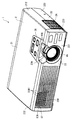
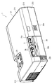
図1は、本発明に係る光学機器としてのプロジェクタ1を上方から見た斜視図である。図2は、プロジェクタ1を後方から見た斜視図である。図3は、プロジェクタ1を下方から見た斜視図である。
【0025】
図1〜図3において、プロジェクタ1は、略直方体状の外装ケース2を備えている。
外装ケース2は、プロジェクタ1の本体部分を収納する筐体であり、アッパーケース21と、ロアーケース22と、これらのケース21,22の前方側を跨るように取り付けられるフロントケース23とを備えて構成される。各ケース21〜23は、それぞれ合成樹脂製である。
【0026】
アッパーケース21は、図2に示すように、プロジェクタ1の天面、側面、および背面をそれぞれ構成する上面部211、側面部212、および背面部213を含んで構成される。
上面部211の前方側には、操作パネル25が設けられている。
アッパーケース21において、操作パネル25の後方側には、上面部211の後方側と背面部213とを跨る凹部21Aが形成されている。この凹部21Aから、外装ケース2に収納された回路基板5の一部が外部に露出している。この外部に露出する回路基板5の一部とは、インターフェース部を構成する各種のコネクタ5Aである。これらのコネクタ5Aを介して、プロジェクタ1には、外部機器が接続される。
【0027】
ロアーケース22は、図3に示すように、プロジェクタ1の底面、側面、および背面をそれぞれ構成する底面部221、側面部222、および背面部223を含んで構成される。
底面部221には、開口部221Xが形成されている。この矩形状の開口部221Xには、ランプカバー24が嵌め込み式で着脱可能に設けられている。さらに、底面部221には、外部から冷却空気を吸入するための吸気口221A,221Bが形成されている。
【0028】
底面部221において、後方側の略中央部分には、プロジェクタ1の脚部を構成する後脚22Rが形成されている。また、底面部221における前方側の左右の隅部には、同じくプロジェクタ1の脚部を構成する前脚22Fがそれぞれ設けられている。つまり、プロジェクタ1は、後脚22Rおよび2つ前脚22Fにより3点で支持されている。
2つの前脚22Fは、それぞれ上下方向に進退可能に構成されており、プロジェクタ1の前後方向および左右方向の傾き(姿勢)を調整して、投写画像の位置合わせができるようになっている。
【0029】
図2に示すように、背面部223において、コネクタ5Aの下側となる部分には、リモコン収納部26が形成されている。このリモコン収納部26には、プロジェクタ1の遠隔操作を行うためのリモートコントローラ(リモコン)26Aが収納される。
また、図2において、背面部223におけるリモコン収納部26の右側には、スピーカ孔22Aが形成され、リモコン収納部26の左側には、インレットコネクタ22Bが設けられている。
【0030】
フロントケース23は、図1に示すように、プロジェクタ1の前面、天面、および側面をそれぞれ構成する前面部231、天面部232、および側面部233を含んで構成される。
フロントケース23には、前面部231および天面部232を跨ぐ開口部23Aが形成されている。この開口部23Aに対応するように、外装ケース2内部には、投写レンズ46が配置されている。この際、開口部23Aから投写レンズ46の一部が外部に露出しており、この露出部分の一部であるレバー46Aを介して、投写レンズ46のズーム操作、フォーカス操作が手動で行えるようになっている。
【0031】
また、前面部231において、前述した開口部23Aの反対側の位置には、開口部としての排気口23Bが形成されている。この排気口23Bの内側には、プロジェクタ1内の空気を誘導する排気ダクト67が設けられており、排気口23Bには、排気ダクト67の排気口67Aが対向している。この排気口23Bには、水平方向に並ぶ複数枚の羽根板23B1が形成され、これらの羽根板23B1により、排気ダクト67の排気口67A等から排出される冷却空気を整流する機能と、内外の光を遮ぎる機能とを備えている。
【0032】
このような外装ケース2の側面側には、図1に示すように、アッパーケース21の側面部212とロアーケース22の側面部222に跨って吸気口2Aが形成されている。この吸気口2Aの内側には、図1〜3では図示しないシロッコファンが設けられている。
【0033】
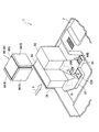
ここで、図4は、プロジェクタ1の内部を示す斜視図である。
外装ケース2には、図4に示すように、プロジェクタ1の前方から見て、略中央の前方側に配置された電源ユニット3と、この電源ユニット3の後方から右側にかけて配置された平面視略L字状の光学ユニット4と、これらのユニット3,4の上方に配置される図示しない前記回路基板とを備える。
【0034】
電源ユニット3は、電源31と、この電源31の下方に配置されたランプ駆動回路(バラスト)32とを含んで構成される。
電源31は、前記インレットコネクタに接続された図示しない電源ケーブルを通して、外部から供給された電力をランプ駆動回路32や前記回路基板等に供給するものである。
ランプ駆動回路32は、光学ユニット4を構成する図4では図示しない光源ランプに、電源31から供給された電力を供給するものであり、前記光源ランプと電気的に接続されている。このようなランプ駆動回路32は、例えば、図示しない基板に配線される。
【0035】
これらの電源31およびランプ駆動回路32は、略平行に上下に並んで配置され、これらの占有空間は、プロジェクタ1の前方で左右方向に延びている。
また、電源31およびランプ駆動回路32は、左右側が開口された筒部材31A,32Aによってそれぞれ周囲を覆われている。これらの筒部材31A,32Aは、冷却空気を誘導するダクトとして機能する。また、筒部材32Aには、その表面にめっき処理等の金属による加工がなされ、ランプ駆動回路32からの電磁ノイズの漏れが防止されている。
さらに、電源31およびランプ駆動回路32は、矩形の開口部分が形成された金属製の下部シールド部材33によって覆われており、これらの電源31およびランプ駆動回路32からの外部への電磁ノイズの漏れが防止されている。
【0036】
前記回路基板は、具体的な図示を省略しているが、CPU等を含む制御部と、接続端子である各種のコネクタ5A(図2)を含むインターフェース部とが実装された一枚の基板であり、コネクタ5Aを介して入力された画像情報に応じて、制御部が、光学装置44を構成する液晶パネルの制御を行っている。
【0037】
この回路基板は、図4に示す下部シールド部材33の上部に配置されるとともに、該回路基板の上方には、図示しないが金属製の上部シールド部材が配置される。この上部シールド部材および下部シールド部材33は、この回路基板を挟んだ状態で互いに固定されている。これにより、電源ユニット3や回路基板等から外部への電磁ノイズの漏れを防止している。
【0038】
〔2.光学ユニットの詳細な構成〕
ここで、図5は、光学ユニット4を模式的に示した平面図である。
光学ユニット4は、図4,5に示すように、光源装置411を構成する光源ランプ416から射出された光束を光学的に処理して画像情報に対応した光学像を形成し、この光学像を拡大して投射するユニットであり、インテグレータ照明光学系41と、色分離光学系42と、リレー光学系43と、光学装置44と、投写光学系としての投写レンズ46と、これらの光学部品41〜46を収納するライトガイド47とを備える。
【0039】
インテグレータ照明光学系41は、光学装置44を構成する3枚の液晶パネル441(赤、緑、青の色光毎にそれぞれ液晶パネル441R,441G,441Bとする)の画像形成領域をほぼ均一に照明するための光学系であり、光源装置411と、第1レンズアレイ412と、第2レンズアレイ413と、偏光変換素子414と、重畳レンズ415とを備えている。
【0040】
光源装置411は、放射光源としての光源ランプ416と、リフレクタ417とを備え、光源ランプ416から射出された放射状の光線をリフレクタ417で反射して平行光線とし、この平行光線を外部へと射出する。
光源ランプ416としては、ハロゲンランプを採用している。なお、ハロゲンランプ以外に、メタルハライドランプや高圧水銀ランプ等も採用できる。
リフレクタ417としては、放物面鏡を採用している。なお、放物面鏡の代わりに、平行化凹レンズおよび楕円面鏡を組み合わせたものを採用してもよい。なお、光源装置411の構造については後で詳説する。
【0041】
第1レンズアレイ412は、光軸方向から見てほぼ矩形状の輪郭を有する小レンズがマトリクス状に配列された構成を有している。各小レンズは、光源ランプ416から射出される光束を、複数の部分光束に分割している。各小レンズの輪郭形状は、液晶パネル441の画像形成領域の形状とほぼ相似形をなすように設定されている。たとえば、液晶パネル441の画像形成領域のアスペクト比(横と縦の寸法の比率)が4:3であるならば、各小レンズのアスペクト比も4:3に設定する。
【0042】
第2レンズアレイ413は、第1レンズアレイ412と略同様な構成を有しており、小レンズがマトリクス状に配列された構成を有している。この第2レンズアレイ413は、重畳レンズ415とともに、第1レンズアレイ412の各小レンズの像を液晶パネル441上に結像させる機能を有する。
【0043】
偏光変換素子414は、第2レンズアレイ413と重畳レンズ415との間に配置されるとともに、第2レンズアレイ413と一体でユニット化されている。このような偏光変換素子414は、第2レンズアレイ413からの光を1種類の偏光光に変換するものであり、これにより、光学装置44での光の利用効率が高められている。
【0044】
具体的に、偏光変換素子414によって1種類の偏光光に変換された各部分光は、重畳レンズ415によって最終的に光学装置44の液晶パネル441上にほぼ重畳される。偏光光を変調するタイプの液晶パネル441を用いたプロジェクタ1では、1種類の偏光光しか利用できないため、他種類のランダムな偏光光を発する光源ランプ416からの光のほぼ半分が利用されない。このため、偏光変換素子414を用いることにより、光源ランプ416から射出された光束を全て1種類の偏光光に変換し、光学装置44での光の利用効率を高めている。
なお、このような偏光変換素子414は、たとえば特開平8−304739号公報に紹介されている。
【0045】
色分離光学系42は、2枚のダイクロイックミラー421,422と、反射ミラー423とを備え、ダイクロイックミラー421、422によりインテグレータ照明光学系41から射出された複数の部分光束を赤(R)、緑(G)、青(B)の3色の色光に分離する機能を有している。
【0046】
リレー光学系43は、入射側レンズ431と、リレーレンズ433と、反射ミラー432、434とを備え、色分離光学系42で分離された色光である赤色光を液晶パネル441Rまで導く機能を有している。
【0047】
この際、色分離光学系42のダイクロイックミラー421では、インテグレータ照明光学系41から射出された光束の赤色光成分と緑色光成分とが透過するとともに、青色光成分が反射する。ダイクロイックミラー421によって反射した青色光は、反射ミラー423で反射し、フィールドレンズ418を通って、青色用の液晶パネル441Bに到達する。このフィールドレンズ418は、第2レンズアレイ413から射出された各部分光束をその中心軸(主光線)に対して平行な光束に変換する。他の液晶パネル441G、441Bの光入射側に設けられたフィールドレンズ418も同様である。
【0048】
また、ダイクロイックミラー421を透過した赤色光と緑色光のうちで、緑色光は、ダイクロイックミラー422によって反射し、フィールドレンズ418を通って、緑色用の液晶パネル441Gに到達する。一方、赤色光は、ダイクロイックミラー422を透過してリレー光学系43を通り、さらにフィールドレンズ418を通って、赤色光用の液晶パネル441Rに到達する。
なお、赤色光にリレー光学系43が用いられているのは、赤色光の光路の長さが他の色光の光路長さよりも長いため、光の拡散等による光の利用効率の低下を防止するためである。すなわち、入射側レンズ431に入射した部分光束をそのまま、フィールドレンズ418に伝えるためである。
【0049】
光学装置44は、入射された光束を画像情報に応じて変調してカラー画像を形成するものであり、色分離光学系42で分離された各色光が入射される3つの入射側偏光板442と、各入射側偏光板442の後段に配置される光変調装置としての液晶パネル441R,441G,441Bと、各液晶パネル441R,441G,441Bの後段に配置される射出側偏光板443と、色合成光学系としてのクロスダイクロイックプリズム444とを備える。
【0050】
液晶パネル441R,441G,441Bは、例えば、ポリシリコンTFTをスイッチング素子として用いたものである。
光学装置44において、色分離光学系42で分離された各色光は、これら3枚の液晶パネル441R,441G,441B、入射側偏光板442、および射出側偏光板443によって、画像情報に応じて変調された光学像を形成する。
【0051】
入射側偏光板442は、色分離光学系42で分離された各色光のうち、一定方向の偏光光のみ透過させ、その他の光束を吸収するものであり、サファイヤガラス等の基板に偏光膜が貼付されたものである。
射出側偏光板443も、入射側偏光板442と略同様に構成され、液晶パネル441(441R,441G,441B)から射出された光束のうち、所定方向の偏光光のみ透過させ、その他の光束を吸収するものである。
これらの入射側偏光板442および射出側偏光板443は、互いの偏光軸の方向が直交するように設定されている。
【0052】
クロスダイクロイックプリズム444は、射出側偏光板443から射出され、各色光毎に変調された光学像を合成してカラー画像を形成するものである。
クロスダイクロイックプリズム444には、赤色光を反射する誘電体多層膜と青色光を反射する誘電体多層膜とが、4つの直角プリズムの界面に沿って略X字状に設けられ、これらの誘電体多層膜により3つの色光が合成される。
【0053】
以上説明した液晶パネル441、射出側偏光板443およびクロスダイクロイックプリズム444は、一体的にユニット化された光学装置本体45として構成されている。なお、入射側偏光板442は、ライトガイド47に形成された図示しない溝部にスライド式に嵌め込んで取り付けられる。
【0054】
図6は、光学装置本体45を示す斜視図である。
光学装置本体45は、図6に示すように、クロスダイクロイックプリズム444と、このクロスダイクロイックプリズム444を下方から支持する金属製の台座451と、クロスダイクロイックプリズム444の光束入射端面に取り付けられ、射出側偏光板443を保持する金属製の保持板452と、この保持板452の光束入射側に取り付けられた4つのピン部材453によって保持される液晶パネル441(441R,441G,441B)とを備えている。保持板452と液晶パネル441との間には、所定間隔の空隙が設けられており、この空隙部分を冷却空気が流れるようになっている。
投写レンズ46は、図4に示すように、光学装置44のクロスダイクロイックプリズム444で合成されたカラー画像を拡大して投写するものである。
【0055】
以上説明した各光学系41〜44は、図4に示すように、光学部品用筐体としての合成樹脂製のライトガイド47内に収容されている。
ライトガイド47は、図4において内部側の具体的な図示を省略するが、図5に示す各光学部品412〜415,418,421〜423,431〜434,442を上方からスライド式に嵌め込む溝部が形成された下ライトガイド471と、下ライトガイド471の上部の開口側を閉塞する蓋状の上ライトガイド472とを備えて構成される。
また、図4において、平面視略L字状のライトガイド47の一端側には、光源装置411が収容され、他端側には、ヘッド部49を介して投写レンズ46がねじ止め固定されている。
【0056】
〔3.冷却構造〕
ここで、プロジェクタ1には、前記液晶パネル441を主に冷却するパネル冷却系Aと、前記電源ユニット3を主に冷却する電源冷却系Cとが設けられている。
ここで、図7は、図4に対して、冷却空気の流れる方向を示す矢印を追加して記載した図であり、電源冷却系Cを含むプロジェクタ1内の冷却空気の流れを示す図である。図8は、光学装置44の下側の構造を模式的に示す斜視図であり、パネル冷却系Aを説明するための図である。
【0057】
図7において、パネル冷却系Aでは、投写レンズ46の右側に配置された2つのシロッコファン61,62が用いられている。また、図8に示すように、パネル冷却系Aでは、これらのファン61,62にそれぞれ接続されるダクト63,64が用いられている。
図8に示すように、シロッコファン61,62は、外装ケース2側面の吸気口2Aから外部の冷却空気を吸入して、この吸引した冷却空気をダクト63,64にそれぞれ排出するものである。なお、シロッコファン62は、シロッコファン61よりも大型のものが採用されている。
【0058】
ダクト63は、シロッコファン61から排出された冷却空気を光学装置44の下方まで誘導するものであり、緑色光用の液晶パネル441Gの下方に対応する位置には、矩形の開口部63Aが形成されている。
また、ダクト64は、シロッコファン62から排出された冷却空気を光学装置44の下方まで誘導するものであり、赤色光用および青色光用の液晶パネル441R,441Bの下方に対応する位置には、矩形の開口部64A,64Bがそれぞれ形成されている。
ここで、図示を省略するが、前記下ライトガイドの底面において、開口部63A,64A,64Bに対応する位置には、開口部が形成されている。
【0059】
従って、図8に示すように、パネル冷却系Aにおいて、シロッコファン61,62によって吸引された冷却空気は、各液晶パネル441R,441G,441Bに加えて、図8では図示しない前記入射側偏光板および前記射出側偏光板も冷却するように流れることになる。
図7において、このように液晶パネル441R,441G,441Bを下方から上方に向けて冷却した冷却空気は、図示しない回路基板の下面を冷却しながら、前方から見て左側の軸流ファン66側に引き寄せられ、図示しない前記外装ケース前面の排気口から排出される。
【0060】
図7において、電源冷却系Cでは、電源ユニット3の右側に設けられた軸流ファン68が用いられている。
軸流ファン68によって、ロアーケース22の底面部221に形成された吸気口221Bから吸引された冷却空気は、電源31およびランプ駆動回路32を冷却しながら、筒部材31A,32Aに沿って前方から見て右側から左側へと流れた後、そのほとんどが他の冷却系統A,Bと同様に、軸流ファン66によって引き寄せらた後に、排気ダクト67を介して、図示しない外装ケース前面の排気口から排出される。なお、一部の空気は、軸流ファン66に引き寄せられずに、直接、前記外装ケースの排気口から排出される。
【0061】
〔4.光源装置の構造〕
次に、光源装置411の構造について説明する。
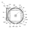
図9は、光源装置411を示す斜視図であり、図10は、この光源装置411を示す分解斜視図である。図11,12は、光源装置411を示す縦断面図である。図13は、ライトガイド47に光源装置411が取り付けられた様子を示す部分斜視図である。図14は、ライトガイド47に取り付けられた光源装置411を示す縦断面図である。
【0062】
光源装置411は、図9に示すように、前述した光源ランプ416およびリフレクタ417と、これらの光源ランプ416およびリフレクタ417が取り付けられる保持部材500と、この保持部材500の光束射出側に取り付けられるリング状のシャッタ部材600と、保持部材500の一部およびシャッタ部材600の一部を繋ぐ弾性部材としてのばね700とを備える。
【0063】
保持部材500は、図10に示すように、光源ランプ416を含むリフレクタ417およびシャッタ部材600を所定位置に保持する合成樹脂製の部材であり、内部が空洞の略直方体状の筐体510と、この筐体510の光束射出面から突出して形成されたリング状の保持部520と、このリング状の保持部520の光束射出面に、はめ込み式に取り付けられるガラス製の透明板530とを備える。
【0064】
筐体510は、上面部511と、下面部512と、左右の側面部513,514と、前面部515とを備え、略直方体状に構成されている。ただし、筐体510の後面部分は、リフレクタ417を取り付けるために開口されている。
また、筐体510は、光源ランプ416を含むリフレクタ417の先端部分が、光束射出方向としての前面部515の内面、およびこの内面に直交する方向としての左側の側面部513の内面に当接され、光源ランプ416を含むリフレクタ417を位置決めして保持する部材である。
【0065】
上面部511および下面部512には、図11に示すように、ライトガイド47の内側に形成された図示しない凹部と係合する突起511A,512Aが形成されている。
また、図11に示すように、前面部515には、略矩形状の開口部515Aが形成されている。光源ランプ416を含むリフレクタ417が筐体510に取り付けられると、図10に示すように、光源ランプ416は開口部515Aから光束射出側へ突出することになる。
さらに、図10において、前面部515の左上端部には、左側面部513の外側へ延びる取り付け部515Bが設けられている。この取り付け部515Bには、ばね700の一端を取り付けるための孔515Cが形成されている。
【0066】
保持部520は、筐体510の光束射出面に形成され、光源ランプ416の光束射出面を囲むとともに、シャッタ部材600を、光源ランプ416の照明光軸を中心として回動自在に保持するものである。
また、保持部520は、光源ランプ416の突出寸法よりも大きな寸法で光束射出側へ突出して構成され、光源ランプ416と透明板530との接触を防止している。
【0067】
保持部520は、断面が、略円形の左右側を垂直方向に切り落としたような形状で、かつ光源ランプ416が筐体510の開口部515Aから突出する寸法よりも大きな寸法で突出する部材であり、上方へ突出する曲面状の上面部521と、下方へ突出する曲面状の下面部522と、左右の側面部523とを備える。
【0068】
上面部521には、通気口である矩形状の排気口521Aが形成されている。なお、図示を省略しているが、この排気口521Aには、エアフィルタが設けられている。また、下面部522には、通気口である矩形状の吸気口522Aが形成されている。図示を省略しているが、排気口521Aと同様に、吸気口522Aにもエアフィルタが設けられている。
これらのエアフィルタにより、リフレクタ417内への外部からの塵埃の侵入と、万が一光源ランプ416が破裂した際の外部への破片の漏れとが防止されている。
これらの吸気口522Aおよび排気口521Aは、光源ランプ416の照明光軸を中心とする対称位置に形成されている。
【0069】
シャッタ部材600は、図10,11に示すように、光源ランプ416の照明光軸を中心軸として、保持部材500を構成する保持部520に対して回動して、吸気口522Aおよび排気口521Aを同時に開閉するように一体的に構成されている。
シャッタ部材600は、保持部520の突出寸法と略同じ幅寸法を有するリング状のシャッタ本体610と、このシャッタ本体610の前面と直交し、この前面からシャッタ本体610の外側へと延びるように形成されたカバー部620と、このシャッタ本体610の外周部分から外側へ突出して形成されたレバー部630とを備える。
【0070】
シャッタ本体610は、リング状の保持部520に対応するリング状に形成され、保持部520に取り付けられて回動する部分であり、保持部520に形成された吸気口522Aおよび排気口521Aに対応する開口部610A,610Bがそれぞれ所定位置に形成されている。
これらの開口部610A,610Bは、図11に示すように、シャッタ本体610が保持部520に取り付けられた際に、光源ランプ416の照明光軸を中心とする対称位置となるように形成されている。
【0071】
カバー部620は、図10に示すように、吸気口522Aおよび排気口521Aが閉じられた際に、最下部側の通気口としての吸気口522Aを覆うものである。このカバー部620は、シャッタ本体610が保持部520に取り付けられると、透明板530と略平行となり、仮に、光源ランプ416が破損した場合でも、この破片が光束射出側へ飛散しないようになっている。
【0072】
レバー部630は、プロジェクタ1のライトガイド47に光源装置411が取り付けられた際に、このライトガイド47の一部によって下方へと付勢される略矩形板状の部分であり、このように付勢されると、保持部520に対してシャッタ部材600が回動するようになっている。また、この付勢が解除された場合には、付勢方向と反対の方向へシャッタ部材600が回動する。
このレバー部630には、ばね700の他端を取り付けるための孔630Aが形成されている。
【0073】
ばね700は、その両端がレバー部630の孔630Aと、取り付け部515Bに形成された孔515Cとに取り付けられ、その収縮力によって、レバー部630と取り付け部515Bとを、互いに近接する方向へと引き寄せるものである。
【0074】
なお、ライトガイド47内に光源装置411が収納されていない場合には、図12に示すように、ばね700の収縮により、図11の状態からシャッタ部材600が矢印Aの方向に回動している。
【0075】
次に、シャッタ部材600の回動による、吸気口522Aおよび排気口521Aの開閉機構について説明する。
ここで、ライトガイド47内に光源装置411が収納されていない場合には、図12に示すように、ばね700の収縮により、図11の状態からシャッタ部材600が矢印Aの方向に回動したような状態となる。
【0076】
図12に示すように、保持部520にシャッタ本体610が取り付けられた状態では、ばね700の収縮力によってレバー部630と取り付け部515Bとが近接し、吸気口522Aおよび排気口521Aの位置と、開口部610A,610Bの位置とがずれて、吸気口522Aおよび排気口521Aが同時に塞がれる。このようにして光源装置411が構成される。
【0077】
図13,14に示すように、このようにして構成された光源装置411がライトガイド47の下部側に形成された開口から収納されると、ライトガイド47の一部である突起47Xがシャッタ部材600のレバー部630と当接して、突起47Xがレバー部630を下方へ、すなわち、ばね700が伸びる方向へ付勢し、シャッタ部材600が図14中の反時計回りに回動する。
図14に示すように、このようにシャッタ部材600が回動すると、吸気口522Aおよび排気口521Aの位置と、開口部610A,610Bの位置とが合致し、吸気口522Aおよび排気口521Aが同時に開放される。
【0078】
ここで、光源装置411をライトガイド47から取り外すと、ライトガイド47の突起47Xとレバー部630との当接が解除されて、ばね700が収縮して、シャッタ部材600が図14中の時計回りに回動する。
このようにシャッタ部材600が図14中の時計回りに回動すると、吸気口522Aおよび排気口521Aの位置と、開口部610A,610Bの位置とがずれた、図12に示す状態となり、吸気口522Aおよび排気口521Aが同時に塞がれる。
【0079】
次に、このような光源装置411を冷却する光源冷却系Bについて説明する。図7において、光源冷却系Bでは、電源ユニット3の下側に設けられた図示しないシロッコファンと、軸流ファン66と、この軸流ファン66に取り付けられた排気ダクト67とが用いられている。
【0080】
前記シロッコファンによって、ロアーケース22の吸気口221A(図3)から吸引された冷却空気は、ロアーケース22の底面部221内側に形成された図示しないガイドに沿って流れた後、図14に示すように、吸気口522Aから光源装置411内に入り込んで光源ランプ416を冷却し、排気口521Aから光源装置411の外へと出ていく。その後、光源装置411から出た冷却空気は、図7に示すように、パネル冷却系Aと同様に、軸流ファン66によって引き寄せられ、排気ダクト67を介して、図示しない外装ケース前面の排気口から排出される。
【0081】
〔5.実施形態の効果〕
本実施形態によれば、以下のような効果がある。
(1)保持部520に設けられた透明板530とリフレクタ417とによって囲まれた空間に対して、冷却空気を流通させる吸気口522Aおよび排気口521Aを保持部520に構成したので、吸気口522Aから排気口521Aへと外部の冷却空気を導いて、リフレクタ417内の光源ランプ416を効率的に冷却でき、光源ランプ416の長寿命化を図ることができる。
【0082】
(2)光源装置411がライトガイド47から取り外された状態では、ばね700の収縮力により、レバー部630と取り付け部515Bとが近接して、吸気口522Aおよび排気口521Aを同時に閉じることができる。
このため、万が一、光源ランプ416の発光管が破裂して光源装置411の交換が必要となった場合でも、ライトガイド47から光源装置411を取り外す際に、シャッタ部材600が吸気口522Aおよび排気口521Aを塞ぐため、これらの破片が光源装置411の外部、すなわちプロジェクタ1の内部へ飛散することを確実に防止できて、プロジェクタ1を確実に動作できる。
【0083】
(3)光源装置411がライトガイド47に取り付けられた状態では、レバー部630とライトガイド47の突起47Xとの当接により、ばね700が延伸して、保持部520に対してシャッタ部材600が回動し、吸気口522Aおよび排気口521Aを同時に開放できる。このため、光源装置411をライトガイド47に収納して、プロジェクタ1の光源として使用する際に、光源ランプ416に確実に冷却空気を送って、光源ランプ416を確実に冷却できる。
【0084】
(4)以上のように、シャッタ部材600を、吸気口522Aおよび排気口521Aの開閉を同時に行う一体的構成の部材としたので、吸気口522Aおよび排気口521Aに対応してシャッタ部材をそれぞれの側に設ける場合に比べて、シャッタ部材の構成部材点数を減少できて、シャッタ部材による開閉の構造を簡素化でき、光源装置411の製造コストを抑えることができる。
【0085】
(5)筐体510の内面や左側の側面部513で光源ランプ416を含むリフレクタ417を所定位置に位置決めするように構成したので、射出成形によって筐体を成形することにより、光源ランプ416の照明光軸の位置を安定させることができる。さらに、このような構成の光源装置411をプロジェクタ1に採用したので、プロジェクタ1は、安定した高品質な画像を投写できる。
【0086】
(6)シャッタ部材600をリング状とし、このリング状のシャッタ部材600に対応するリング状の保持部520を設けて光源装置411を構成したので、保持部520にシャッタ部材600を取り付けるだけで、これらのリング状の曲面に沿ってシャッタ部材600を滑らかに回動できる。このようなリング状という簡単な形状でありながら、シャッタ部材600を確実に回動させることができ、光源装置411の製造コストを抑えることができる。
【0087】
(7)シャッタ部材600には、吸気口522Aおよび排気口521Aが閉じられた際に、光源装置411の下側に位置する吸気口522Aを覆うカバー部620を形成したので、万が一光源ランプ416が破裂して、シャッタ部材600と吸気口522Aとの隙間から光源ランプ416の破片がはみ出たとしても、これらの破片が集まる下側の吸気口522Aをカバー部620によって二重に覆ったので、これらの破片の飛散をより一層確実に防止できる。
【0088】
(8)吸気口522Aおよび排気口521Aを、光源ランプ416の照明光軸を中心とする対称位置に形成したので、リフレクタ417内全体に冷却空気を導入して、リフレクタ417内に滞留する熱を確実に外部へと排出でき、光源ランプ416の冷却効率をさらに高めて、光源ランプ416の長寿命化をより一層図ることができる。
【0089】
(9)保持部520において、下側に吸気口522Aを形成し、上側に排気口521Aを形成したので、光源ランプ416によって熱せられた空気が上方へ流れることから、この熱風を光源装置411の外部へと確実に排出できる。
【0090】
(10)ばね700によって、シャッタ部材600のレバー部630と保持部520に設けられた取り付け部515Bとを接続して、保持部520に対してシャッタ部材600が回動する簡単な構成で、吸気口522Aおよび排気口521Aの同時開閉を確実にかつ簡単に行うことができる。
【0091】
〔6.実施形態の変形〕
なお、本発明は、前記実施形態に限定されるものではなく、本発明の目的を達成できる他の構成等を含み、以下に示すような変形等も本発明に含まれる。
例えば、前記実施形態において、保持部520には、下側に吸気口522Aを1つ形成し、上側に排気口521Aを1つ形成し、これらの吸気口522Aおよび排気口521Aが光源ランプ416の照明光軸を中心とした対称位置に構成したが、これとは逆に、上側に吸気口522Aを形成し下側に排気口521Aを形成してもよい。
また、吸気口522Aおよび排気口521Aは、保持部520の各側において、それぞれ2つ以上形成してもよい。
さらに、吸気口522Aおよび排気口521Aは、照明光軸を中心とした対称位置ではない位置に構成してもよい。
また、吸気口522Aおよび排気口521Aは、例えば、保持部520の左右側等の上下側以外の位置に形成してもよい。
要するに、吸気口522Aおよび排気口521Aにおいて、保持部520における位置、互いの相対位置、形状、数等は特に限定されないということである。なお、これらの吸気口522Aおよび排気口521Aは、保持部520ではなく、リフレクタ417に形成してもよいし、透明板530の一部を切り欠いて構成してもよい。
【0093】
前記実施形態において、シャッタ部材600をリング状としたが、これに限らず、摺動する方向にあわせて、矩形状等のその他の形状としもよく、滑らかに摺動できれば、特にその形状は限定されない。
【0094】
前記各実施形態において、3つの光変調装置を用いたプロジェクタを採用したが、これに限らず、例えば、1つの光変調装置のみを用いたプロジェクタ、2つの光変調装置を用いたプロジェクタ、あるいは、4つ以上の光変調装置を用いたプロジェクタであってもよい。
【0095】
前記各実施形態において、光変調装置として液晶パネルを採用したが、これに限らず、例えば、マイクロミラーを用いたデバイス等の液晶以外の光変調装置を採用してもよい。さらに、前記実施形態では、透過型の光変調装置を用いたが、反射型の光変調装置を用いてもよい。
【0096】
前各記実施形態では、スクリーンを観察する方向から投写を行なうフロントタイプのプロジェクタとしたが、スクリーンの観察方向の後ろ側から投写を行なうリアタイプのプロジェクタにも適用可能である。
その他、本発明の実施時の具体的な構造および形状等は、本発明の目的を達成できる範囲で他の構造等としてもよい。
【0097】
【発明の効果】
本発明によれば、光源ランプが破裂した際に、その破片を外部に飛散させることなく、光源ランプを効率的に冷却して光源ランプの長寿命化を図ることができるとともに、機構を簡素化して部材点数を減少できて製造コストを抑えることができるいう効果がある。
【図面の簡単な説明】
【図1】本発明に係るプロジェクタを上方から見た斜視図である。
【図2】前記プロジェクタを後方から見た斜視図である。
【図3】前記プロジェクタを下方から見た斜視図である。
【図4】前記プロジェクタの内部を示す斜視図であり、具体的には、図1の状態から前記プロジェクタを構成するフロントケース、上部シールド部材、回路基板を外した図である。
【図5】前記プロジェクタを構成する光学ユニットを模式的に示す平面図である。
【図6】前記光学ユニットを構成する光学装置の一部である光学装置本体を示す斜視図である。
【図7】図4に対して、冷却空気の流れる方向を示す矢印を追加して記載した図であり、電源冷却系を含む前記プロジェクタ内の冷却空気の流れを示す図である。
【図8】前記プロジェクタにおいて、前記光学装置の下側の構造を模式的に示す斜視図であり、パネル冷却系を説明するための図である。
【図9】前記プロジェクタを構成する光源装置を示す斜視図である。
【図10】前記光源装置を示す分解斜視図である。
【図11】前記光源装置を示す縦断面図である。
【図12】前記光源装置を示す縦断面図である。
【図13】前記プロジェクタを構成するライトガイドに前記光源装置が取り付けられた様子を示す部分斜視図である。
【図14】前記ライトガイドに前記光源装置が取り付けられた様子を示す縦断面図である。
【符号の説明】
1 光学機器としてのプロジェクタ
47 ライトガイド
47X 突起
411 光源装置
416 光源ランプ
417 リフレクタ
500 保持部材
510 筐体
515B 保持部材の一端である取り付け部
520 保持部
521A 複数の通気口を構成する排気口
522A 複数の通気口を構成する吸気口
530 透明板
600 リング状のシャッタ部材
610A,610B 複数の通気口を構成する開口部
620 カバー部
630 レバー部
700 弾性部材としてのばね
B 光源冷却系[0001]
BACKGROUND OF THE INVENTION
The present invention includes a light source device and the light source device.projectorAbout.
[0002]
[Background]
Conventionally, projectors are used for presentations such as conferences and academic meetings. Such a projector modulates a light beam emitted from a light source lamp of a light source device according to image information to form an optical image, and enlarges and projects this optical image. In recent projectors, it has been required to increase the brightness of a light source lamp in order to display a projected optical image clearly.
[0003]
Here, as the light source lamp of the projector, a high-pressure mercury lamp, a metal halide lamp, or the like is used. With the life of the light source lamp, an arc tube made of quartz glass or the like is ruptured, and the fragments are in the projector. There is a risk of splashing.
Further, since the light source lamp generates a large amount of heat as its brightness increases, it is necessary to prevent the light source lamp from bursting by discharging the heat to the outside and cooling it.
[0004]
Therefore, a conventional light source device including a light source lamp is provided with the following mechanism. That is, the light beam exit side of the reflector is covered with a transparent plate made of glass or the like, and a plurality of vent holes serving as an intake port and an exhaust port are provided in a part of the reflector or the transparent plate. Furthermore, a lid member (shutter member) corresponding to each of these vents is provided, and when the optical device is attached to the projector, each lid member opens the respective vent, and the optical device When removed from the projector, each lid member closes the corresponding vent. With such a mechanism, cooling of the light source lamp and prevention of scattering of fragments at the time of lamp burst are achieved.
[0005]
[Problems to be solved by the invention]
However, in the mechanism of the light source device described above, a lid member corresponding to each vent hole must be provided to open and close each vent hole. This mechanism becomes complicated, and the members constituting this mechanism There is a problem in that the number of points increases and the manufacturing cost of the light source device increases.
Such a problem occurs not only in the light source device used for the projector but also in the light source device used in other optical devices such as an illumination device.
[0006]
The object of the present invention is to increase the life of the light source lamp by effectively cooling the light source lamp without scattering the fragments when the light source lamp is ruptured. And a light source device that can reduce the number of members and reduce the manufacturing cost, and the light source deviceprojectorIs to provide.
[0007]
[Means for Solving the Problems]
A light source device according to the present invention holds a light source lamp, a reflector that aligns and emits a light beam emitted from the light source lamp, and positions and holds the light source lamp and the reflector in a light beam emission direction and a direction orthogonal thereto. A light source device including a holding member, wherein the holding member is formed in the vicinity of the light beam emission surface of the reflector and the transparent plate covering the light beam emission surface side of the reflector, and introduces cooling air to the light source lamp from the outside And an integral shutter member that slides relative to the holding member and simultaneously opens and closes the plurality of ventilation holes.The shutter member rotates about the illumination optical axis of the light source lamp.It is characterized by that.
[0008]
Here, the plurality of vent holes are openings used as an intake port and an exhaust port, and can be configured as, for example, a pair of openings formed on the upper and lower sides and the left and right sides of the holding member. In this case, the cooling air can be circulated in the vertical direction or the horizontal direction in the reflector, and the light source lamp in the reflector can be efficiently cooled.
[0010]
In addition, as a shutter member that opens and closes a plurality of vents at the same time, for example, openings having substantially the same shape are formed at positions corresponding to the vents. It is possible to adopt a configuration in which the vent is matched or displaced. Furthermore, it is also possible to employ a configuration in which a lid portion corresponding to a plurality of vent holes is formed on the shutter member, and the lid portion matches or shifts with the vent port as the shutter member slides.
[0011]
Further, the holding member is formed with a positioning surface for positioning the light source lamp and the reflector in the illumination optical axis direction of the light source lamp and in a direction orthogonal to the illumination optical axis. For example, as a resin molded product by injection molding or the like By molding, the positions of the light source lamp and the reflector can be accurately specified.
[0012]
According to the present invention, since the reflector including the light source lamp is positioned and held on the holding member in a state where the transparent plate covering the light beam exit surface side of the reflector is provided on the holding member, a plurality of ventilation holes formed on the holding member are provided. It is possible to efficiently cool the light source lamp in the reflector by guiding the cooling air from one of the vents to the other vent, and to extend the life of the light source lamp.
[0013]
Here, in the light source device of the present invention, the shutter member can be configured such that the plurality of vents are simultaneously opened when attached to an optical device or the like, and the plurality of vents are simultaneously closed when detached from the optical device. . In such a configuration, when the light source device is attached to the optical device, even if the light-emitting tube of the light source lamp ruptures and the light source device needs to be replaced, these fragments are outside the light source device, that is, the optical device, It is possible to surely prevent scattering into the interior of the projector, and to operate the optical apparatus and the like reliably. In addition, when the shutter member is attached to an optical device or the like, the shutter member opens a plurality of vents at the same time, so that the cooling of the light source lamp is not impaired.
[0014]
Further, since the shutter member is a single member configured to open and close a plurality of vents simultaneously, for example, a shutter member corresponding to each vent is prepared as a separate member. Since it is not necessary to employ a complicated configuration in which the shutter member slides to open and close the vents, the number of members can be reduced, and the open / close structure can be simplified, thereby reducing the manufacturing cost of the light source device. Can do.
[0015]
further,The shutter member,Rotate around the illumination light axis of the light source lampBecauseWhen the plurality of vents are simultaneously opened and closed by sliding the shutter member, the shutter member slides within the light source device without jumping out to the outside or the like, so that the light source device can be downsized. In addition, the structure of a storage part such as an optical device in which the light source device is stored can be simplified.
[0016]
The shutter member is configured in a ring shape, and is formed in a ring shape so as to surround the light beam emission surface of the light source lamp on the light beam emission surface of the holding member, and rotatably holds the shutter member. It is preferable that a holding part is provided.
Here, as the holding member, for example, a holding portion that holds a ring-shaped shutter member and a holding member body that holds the reflector including the light source lamp in a correct posture can be configured.
In addition, as a shape of a holding | maintenance part, it is good also as a ring shape with a circular cross section, and it is good also as a cross-sectional shape which cut off both ends of this circle | round | yen.
[0017]
In such a configuration, for example, the shutter member can be smoothly rotated along the curved surface of the holding portion only by attaching the ring-shaped shutter member to the ring-shaped holding portion corresponding to the ring shape. At this time, the shutter member can be reliably rotated with respect to the holding portion even though it is a simple member, and the manufacturing cost of the light source device can be suppressed.
[0018]
Furthermore, it is preferable that the shutter member is formed with a cover portion that covers at least the ventilation port located on the lowermost side among the plurality of ventilation ports when the plurality of ventilation ports are closed.
With such a configuration, even if a fragment of the light source lamp protrudes from the gap between the shutter member and the vent, the lowermost side vent where the debris collects is doubly covered with the cover, Can be prevented more reliably.
[0019]
In the above light source device, it is preferable that the plurality of vent holes are formed at symmetrical positions around the illumination optical axis of the light source lamp in the holding member.
In such a configuration, since the vents are formed at symmetrical positions of the illumination optical axis, the cooling air is introduced to the entire inside of the reflector, and the heat staying in the reflector can be surely discharged to the outside. The cooling efficiency of the lamp can be increased and the life of the light source lamp can be further extended.
[0020]
Here, it is preferable that at least one of the plurality of vent holes is formed on the upper and lower sides of the holding member.
In such a configuration, for example, when cooling air is introduced from the lower vent and hot air is discharged from the upper vent, the hot air flows upward. It can be reliably discharged outside the light source device.
On the other hand, when cooling air is introduced from the upper vent and hot air is discharged from the lower vent, the hot air stays on the upper side of the reflector. By rapidly cooling, the life of the light source device including the reflector can be extended.
[0021]
In the light source device as described above, the shutter member is integrally configured with a lever portion,SaidBetween the lever part and one end of the holding member,SaidAn elastic member that pulls the lever portion and the holding member in a direction close to each other is provided,SaidWhen the light source device is attached to the optical device, the lever portionSaidIt is preferable that the shutter member slides in a certain direction with respect to the holding member by being biased in a direction opposite to the approaching direction by a part of the optical device.
[0022]
Here, a spring, rubber, resin, or the like can be employed as the elastic member.As the optical device, for example, a projector including a liquid crystal projector and an overhead projector, and various optical devices including a lighting device can be employed.
In such a case, in the state in which the light source device is detached from the optical device, the lever portion and the holding member are attracted by the elastic member, and the plurality of vents are closed at the same time. In a state where the apparatus is attached, the lever portion and the holding member are urged in a direction opposite to the pulling direction by a part of the optical device, and the integrally formed shutter member slides with respect to the holding member. And can be configured to open multiple vents simultaneously.
With such a configuration, the opening and closing of the air vent can be reliably and easily performed by simply forming a lever portion on the shutter member and providing an elastic member that connects the lever portion and one end of the holding member. Can be done.
[0023]
According to the present inventionprojectorIs provided with the light source device described above..
BookAccording to the invention, it is possible to achieve substantially the same operation and effect as the light source device described above.
[0024]
DETAILED DESCRIPTION OF THE INVENTION
Hereinafter, embodiments of the present invention will be described with reference to the drawings.
[1. (Main projector configuration)
FIG. 1 is a perspective view of a
[0025]
1 to 3, the
The
[0026]
As shown in FIG. 2, the
An
In the
[0027]
As shown in FIG. 3, the
An
[0028]
In the
Each of the two
[0029]
As shown in FIG. 2, a remote
In FIG. 2, a
[0030]
As shown in FIG. 1, the
The
[0031]
Further, an
[0032]
As shown in FIG. 1, an
[0033]
Here, FIG. 4 is a perspective view showing the inside of the
As shown in FIG. 4, the
[0034]
The
The
The
[0035]
The
Further, the
Furthermore, the
[0036]
Although not specifically shown, the circuit board is a single board on which a control unit including a CPU and the like and an interface unit including
[0037]
The circuit board is disposed on the
[0038]
[2. Detailed configuration of the optical unit)
Here, FIG. 5 is a plan view schematically showing the
As shown in FIGS. 4 and 5, the
[0039]
The integrator illumination
[0040]
The
As the
A parabolic mirror is employed as the
[0041]
The
[0042]
The
[0043]
The
[0044]
Specifically, each partial light converted into one type of polarized light by the
Such a
[0045]
The color separation
[0046]
The relay
[0047]
At this time, the
[0048]
Of the red light and green light transmitted through the
The relay
[0049]
The
[0050]
The
In the
[0051]
The incident-side
The exit-side
The incident
[0052]
The cross
The cross
[0053]
The
[0054]
FIG. 6 is a perspective view showing the optical device
As shown in FIG. 6, the optical device
As shown in FIG. 4, the
[0055]
Each optical system 41-44 demonstrated above is accommodated in the
The
In FIG. 4, the
[0056]
[3. (Cooling structure)
Here, the
Here, FIG. 7 is a diagram in which an arrow indicating the direction in which the cooling air flows is added to FIG. 4, and is a diagram illustrating the flow of the cooling air in the
[0057]
In FIG. 7, the panel cooling system A uses two
As shown in FIG. 8, the
[0058]
The
The
Here, although not shown, openings are formed at positions corresponding to the
[0059]
Therefore, as shown in FIG. 8, in the panel cooling system A, the cooling air sucked by the
In FIG. 7, the cooling air that has cooled the
[0060]
In FIG. 7, the power supply cooling system C uses an
The cooling air sucked from the
[0061]
[4. Structure of light source device]
Next, the structure of the
FIG. 9 is a perspective view showing the
[0062]
As shown in FIG. 9, the
[0063]
As shown in FIG. 10, the holding
[0064]
The
Further, in the
[0065]
As shown in FIG. 11,
In addition, as shown in FIG. 11, a substantially
Further, in FIG. 10, a mounting
[0066]
The holding
In addition, the holding
[0067]
The holding
[0068]
The
By these air filters, entry of dust from the outside into the
The
[0069]
As shown in FIGS. 10 and 11, the
The
[0070]
The
As shown in FIG. 11, these
[0071]
As shown in FIG. 10, the
[0072]
The
The
[0073]
Both ends of the
[0074]
When the
[0075]
Next, an opening / closing mechanism for the
Here, when the
[0076]
As shown in FIG. 12, in a state where the shutter
[0077]
As shown in FIGS. 13 and 14, when the
As shown in FIG. 14, when the
[0078]
Here, when the
When the
[0079]
Next, the light source cooling system B that cools the
[0080]
The cooling air sucked from the
[0081]
[5. Effects of the embodiment
According to this embodiment, there are the following effects.
(1) Since the
[0082]
(2) When the
For this reason, even if the light-emitting tube of the
[0083]
(3) In a state where the
[0084]
(4) As described above, since the
[0085]
(5) Since the
[0086]
(6) Since the
[0087]
(7) Since the
[0088]
(8) Since the
[0089]
(9) In the holding
[0090]
(10) The
[0091]
[6. Modification of Embodiment]
In addition, this invention is not limited to the said embodiment, Including other structures etc. which can achieve the objective of this invention, the deformation | transformation etc. which are shown below are also contained in this invention.
For example, in the embodiment, the holding
Further, two or
Further, the
Further, the
In short, in the
[0093]
In the above-described embodiment, the
[0094]
In each of the above embodiments, a projector using three light modulation devices is employed. However, the present invention is not limited to this. For example, a projector using only one light modulation device, a projector using two light modulation devices, or A projector using four or more light modulation devices may be used.
[0095]
In each of the embodiments, the liquid crystal panel is used as the light modulation device. However, the present invention is not limited to this. For example, a light modulation device other than liquid crystal such as a device using a micromirror may be used. Furthermore, in the above-described embodiment, the transmission type light modulation device is used, but a reflection type light modulation device may be used.
[0096]
In each of the embodiments described above, a front type projector that performs projection from the direction in which the screen is observed is used. However, the present invention can also be applied to a rear type projector that performs projection from the rear side in the viewing direction of the screen.
In addition, the specific structure, shape, and the like when the present invention is implemented may be other structures as long as the object of the present invention can be achieved.
[0097]
【The invention's effect】
According to the present invention, when the light source lamp is ruptured, the light source lamp can be efficiently cooled without extending the fragments to the outside, thereby extending the life of the light source lamp and simplifying the mechanism. Thus, there is an effect that the number of members can be reduced and the manufacturing cost can be suppressed.
[Brief description of the drawings]
FIG. 1 is a perspective view of a projector according to the present invention as viewed from above.
FIG. 2 is a perspective view of the projector as viewed from the rear.
FIG. 3 is a perspective view of the projector as viewed from below.
4 is a perspective view showing the inside of the projector. Specifically, FIG. 4 is a view in which a front case, an upper shield member, and a circuit board constituting the projector are removed from the state of FIG.
FIG. 5 is a plan view schematically showing an optical unit constituting the projector.
FIG. 6 is a perspective view showing an optical device body which is a part of an optical device constituting the optical unit.
7 is a diagram in which an arrow indicating a direction in which cooling air flows is added to FIG. 4 and is a diagram illustrating a flow of cooling air in the projector including a power supply cooling system.
FIG. 8 is a perspective view schematically showing a lower structure of the optical device in the projector, for explaining a panel cooling system.
FIG. 9 is a perspective view showing a light source device constituting the projector.
FIG. 10 is an exploded perspective view showing the light source device.
FIG. 11 is a longitudinal sectional view showing the light source device.
FIG. 12 is a longitudinal sectional view showing the light source device.
FIG. 13 is a partial perspective view showing a state in which the light source device is attached to a light guide constituting the projector.
FIG. 14 is a longitudinal sectional view showing a state in which the light source device is attached to the light guide.
[Explanation of symbols]
1 Projector as an optical device
47 Light Guide
47X protrusion
411 Light source device
416 Light source lamp
417 Reflector
500 Holding member
510 housing
515B The attachment part which is one end of a holding member
520 holder
521A Exhaust ports constituting a plurality of vent holes
522A Intake port constituting a plurality of vents
530 transparent plate
600 Ring-shaped shutter member
610A, 610B Openings constituting a plurality of vents
620 Cover part
630 Lever part
700 Spring as an elastic member
B Light source cooling system
Claims (7)
前記保持部材は、前記リフレクタの光束射出面側を覆う透明板と、前記リフレクタの光束射出面近傍に形成され、外部から前記光源ランプに冷却空気を導入する複数の通気口とを備え、
前記保持部材の光束射出部分には、該保持部材に対して摺動し、前記複数の通気口を同時に開閉する一体的なシャッタ部材が設けられ、
前記シャッタ部材は、前記光源ランプの照明光軸を軸として回動することを特徴とする光源装置。A light source device comprising: a light source lamp; a reflector that aligns and emits light beams emitted from the light source lamp; and a holding member that positions and holds the light source lamp and the reflector in a light beam emission direction and a direction perpendicular thereto. There,
The holding member includes a transparent plate that covers a light beam emission surface side of the reflector, and a plurality of vent holes that are formed in the vicinity of the light beam emission surface of the reflector and introduce cooling air into the light source lamp from the outside.
An integral shutter member that slides with respect to the holding member and simultaneously opens and closes the plurality of vent holes is provided at the light beam emission portion of the holding member ,
The light source device , wherein the shutter member rotates about an illumination optical axis of the light source lamp .
前記シャッタ部材は、リング状に構成され、
前記保持部材の光束射出面には、前記光源ランプの光束射出面を囲むようにリング状に形成され、前記シャッタ部材を回動自在に保持する保持部が設けられていることを特徴とする光源装置。The light source device according to claim 1,
The shutter member is configured in a ring shape,
The light emitting surface of the holding member is provided with a holding portion that is formed in a ring shape so as to surround the light emitting surface of the light source lamp and rotatably holds the shutter member. apparatus.
前記シャッタ部材には、前記複数の通気口が閉じられた際に、少なくとも複数の通気口のうち、最も下部側に位置する通気口を覆うカバー部が形成されていることを特徴とする光源装置。The light source device according to claim 2,
The light source device is characterized in that the shutter member is formed with a cover portion that covers a ventilation port located at a lowermost side among the plurality of ventilation ports when the plurality of ventilation ports are closed. .
前記複数の通気口は、前記保持部材において前記光源ランプの照明光軸を中心とする対称位置に形成されていることを特徴とする光源装置。In the light source device in any one of Claims 1-3,
The light source device according to claim 1, wherein the plurality of vent holes are formed at symmetrical positions around the illumination optical axis of the light source lamp in the holding member.
前記複数の通気口は、前記保持部材の上下側に少なくとも1つずつ形成されていることを特徴とする光源装置。The light source device according to claim 4,
The light source device according to claim 1, wherein the plurality of vent holes are formed at least one on each of upper and lower sides of the holding member.
前記シャッタ部材には、レバー部が一体的に構成され、
前記レバー部と前記保持部材の一端との間には、前記レバー部と保持部材とを互いに近接する方向に引き寄せる弾性部材が設けられ、
前記レバー部は、光学機器に該光源装置が取り付けられた際に、前記光学機器の一部によって、前記近接する方向とは反対の方向に付勢されて、前記保持部材に対して該シャッタ部材が一定方向に摺動することを特徴とする光源装置。In the light source device according to any one of claims 1 to 5,
The shutter member is configured integrally with a lever portion,
Between the lever part and one end of the holding member, an elastic member is provided that pulls the lever part and the holding member in directions close to each other,
The lever portion is urged in a direction opposite to the approaching direction by a part of the optical device when the light source device is attached to the optical device, and the shutter member is pressed against the holding member. Slides in a certain direction.
Priority Applications (1)
| Application Number | Priority Date | Filing Date | Title |
|---|---|---|---|
| JP2002014824A JP4055420B2 (en) | 2002-01-23 | 2002-01-23 | Light source device and projector provided with the light source device |
Applications Claiming Priority (1)
| Application Number | Priority Date | Filing Date | Title |
|---|---|---|---|
| JP2002014824A JP4055420B2 (en) | 2002-01-23 | 2002-01-23 | Light source device and projector provided with the light source device |
Publications (3)
| Publication Number | Publication Date |
|---|---|
| JP2003215706A JP2003215706A (en) | 2003-07-30 |
| JP2003215706A5 JP2003215706A5 (en) | 2005-08-11 |
| JP4055420B2 true JP4055420B2 (en) | 2008-03-05 |
Family
ID=27651394
Family Applications (1)
| Application Number | Title | Priority Date | Filing Date |
|---|---|---|---|
| JP2002014824A Expired - Fee Related JP4055420B2 (en) | 2002-01-23 | 2002-01-23 | Light source device and projector provided with the light source device |
Country Status (1)
| Country | Link |
|---|---|
| JP (1) | JP4055420B2 (en) |
Families Citing this family (2)
| Publication number | Priority date | Publication date | Assignee | Title |
|---|---|---|---|---|
| JP4221353B2 (en) | 2004-11-19 | 2009-02-12 | Necディスプレイソリューションズ株式会社 | Light source device and projection display device |
| JP4603523B2 (en) | 2006-10-06 | 2010-12-22 | Necディスプレイソリューションズ株式会社 | Lamp unit and projector using the same |
Family Cites Families (17)
| Publication number | Priority date | Publication date | Assignee | Title |
|---|---|---|---|---|
| JPH0676603A (en) * | 1992-08-31 | 1994-03-18 | Eye Lighting Syst Corp | Lighting device for photographing |
| JP2702868B2 (en) * | 1993-04-12 | 1998-01-26 | カシオ計算機株式会社 | LCD projector |
| JP3473858B2 (en) * | 1993-09-10 | 2003-12-08 | 株式会社ウシオスペックス | Tilt |
| JP3316978B2 (en) * | 1993-11-09 | 2002-08-19 | 株式会社豊田自動織機 | Sliver grasping and collecting device of working machine in spinning machine |
| JP3275755B2 (en) * | 1997-01-31 | 2002-04-22 | ウシオ電機株式会社 | Light irradiation unit |
| JPH10254061A (en) * | 1997-03-07 | 1998-09-25 | Seiko Epson Corp | Light source device and projection type display device |
| JPH10313703A (en) * | 1997-05-22 | 1998-12-02 | Gutsupii:Kk | Plant growing container |
| JP3841950B2 (en) * | 1998-02-24 | 2006-11-08 | 三菱電機株式会社 | Lamp box and projector device |
| JP2000056396A (en) * | 1998-08-04 | 2000-02-25 | Mitsubishi Electric Corp | Projector device and lamp box |
| JP2000200511A (en) * | 1998-10-30 | 2000-07-18 | Phoenix Denki Kk | Discharge lamp |
| JP2000348532A (en) * | 1999-06-03 | 2000-12-15 | Plus Property Corp | Heat radiating and cooling structure of lamp |
| JP3700571B2 (en) * | 1999-10-15 | 2005-09-28 | ソニー株式会社 | Projection display |
| JP3667588B2 (en) * | 2000-03-10 | 2005-07-06 | Necビューテクノロジー株式会社 | Lamp house and its projector device |
| JP3675293B2 (en) * | 2000-04-05 | 2005-07-27 | ウシオ電機株式会社 | Light source device |
| JP2001330890A (en) * | 2000-05-22 | 2001-11-30 | Matsushita Electric Ind Co Ltd | Light source device and projection type display device |
| JP2002075014A (en) * | 2000-06-16 | 2002-03-15 | Matsushita Electric Ind Co Ltd | Lamp unit and image projection device |
| JP3512745B2 (en) * | 2001-01-18 | 2004-03-31 | 松下電器産業株式会社 | Light source device and projector using the same |
-
2002
- 2002-01-23 JP JP2002014824A patent/JP4055420B2/en not_active Expired - Fee Related
Also Published As
| Publication number | Publication date |
|---|---|
| JP2003215706A (en) | 2003-07-30 |
Similar Documents
| Publication | Publication Date | Title |
|---|---|---|
| JP3829813B2 (en) | projector | |
| JP3664065B2 (en) | Light source device and projector | |
| JP3467697B2 (en) | Cooling device for electro-optical device and projector | |
| US6793343B2 (en) | Projector provided with cooling mechanism | |
| US6886948B2 (en) | Electronics exterior case and projector having the same | |
| WO2002097529A1 (en) | Projector | |
| JP2008257175A (en) | Power source unit and projection type image display apparatus using the same | |
| JP4020119B2 (en) | projector | |
| US8414133B2 (en) | Projection display device having an operation section for displacing a lens | |
| JP4046119B2 (en) | Lighting device, projector | |
| JP5140379B2 (en) | Optical component cooling mechanism and projection display apparatus using the same | |
| US7086745B2 (en) | Optical component casing, optical device and projector | |
| WO2004079447A1 (en) | Projector | |
| JP2002287253A (en) | Attaching structure of optical component and projector | |
| JP2007057996A (en) | Projector | |
| JP4055420B2 (en) | Light source device and projector provided with the light source device | |
| JP2004071498A (en) | Explosion-proof filter, light equipment equipped with it, projector equipped with it and manufacturing method of explosion-proof filter | |
| JP2003287816A (en) | Duct with louver board and projector provided with the duct with louver board | |
| JP3558084B2 (en) | projector | |
| JP3991745B2 (en) | Optical component housing and projector | |
| JP2002350976A (en) | Light source device and optical instrument using the same | |
| JP2006072138A (en) | Rear projector | |
| JP2011150141A (en) | Image projection device | |
| JP2005003955A (en) | Duct, cooling device and projector | |
| JP2009145448A (en) | Projector |
Legal Events
| Date | Code | Title | Description |
|---|---|---|---|
| A521 | Written amendment |
Free format text: JAPANESE INTERMEDIATE CODE: A523 Effective date: 20050120 |
|
| A621 | Written request for application examination |
Free format text: JAPANESE INTERMEDIATE CODE: A621 Effective date: 20050120 |
|
| A977 | Report on retrieval |
Free format text: JAPANESE INTERMEDIATE CODE: A971007 Effective date: 20061228 |
|
| RD02 | Notification of acceptance of power of attorney |
Free format text: JAPANESE INTERMEDIATE CODE: A7422 Effective date: 20070704 |
|
| A131 | Notification of reasons for refusal |
Free format text: JAPANESE INTERMEDIATE CODE: A131 Effective date: 20070731 |
|
| RD02 | Notification of acceptance of power of attorney |
Free format text: JAPANESE INTERMEDIATE CODE: A7422 Effective date: 20070813 |
|
| A521 | Written amendment |
Free format text: JAPANESE INTERMEDIATE CODE: A523 Effective date: 20070905 |
|
| TRDD | Decision of grant or rejection written | ||
| A01 | Written decision to grant a patent or to grant a registration (utility model) |
Free format text: JAPANESE INTERMEDIATE CODE: A01 Effective date: 20071120 |
|
| A61 | First payment of annual fees (during grant procedure) |
Free format text: JAPANESE INTERMEDIATE CODE: A61 Effective date: 20071203 |
|
| R150 | Certificate of patent or registration of utility model |
Free format text: JAPANESE INTERMEDIATE CODE: R150 |
|
| FPAY | Renewal fee payment (event date is renewal date of database) |
Free format text: PAYMENT UNTIL: 20101221 Year of fee payment: 3 |
|
| FPAY | Renewal fee payment (event date is renewal date of database) |
Free format text: PAYMENT UNTIL: 20101221 Year of fee payment: 3 |
|
| FPAY | Renewal fee payment (event date is renewal date of database) |
Free format text: PAYMENT UNTIL: 20111221 Year of fee payment: 4 |
|
| FPAY | Renewal fee payment (event date is renewal date of database) |
Free format text: PAYMENT UNTIL: 20111221 Year of fee payment: 4 |
|
| FPAY | Renewal fee payment (event date is renewal date of database) |
Free format text: PAYMENT UNTIL: 20121221 Year of fee payment: 5 |
|
| LAPS | Cancellation because of no payment of annual fees |