EP1837976A2 - Système de chargement et bloc-batterie - Google Patents
Système de chargement et bloc-batterie Download PDFInfo
- Publication number
- EP1837976A2 EP1837976A2 EP07110412A EP07110412A EP1837976A2 EP 1837976 A2 EP1837976 A2 EP 1837976A2 EP 07110412 A EP07110412 A EP 07110412A EP 07110412 A EP07110412 A EP 07110412A EP 1837976 A2 EP1837976 A2 EP 1837976A2
- Authority
- EP
- European Patent Office
- Prior art keywords
- charging
- battery
- battery pack
- voltage
- temperature
- Prior art date
- Legal status (The legal status is an assumption and is not a legal conclusion. Google has not performed a legal analysis and makes no representation as to the accuracy of the status listed.)
- Withdrawn
Links
Images


Classifications
-
- H—ELECTRICITY
- H02—GENERATION; CONVERSION OR DISTRIBUTION OF ELECTRIC POWER
- H02J—CIRCUIT ARRANGEMENTS OR SYSTEMS FOR SUPPLYING OR DISTRIBUTING ELECTRIC POWER; SYSTEMS FOR STORING ELECTRIC ENERGY
- H02J7/00—Circuit arrangements for charging or depolarising batteries or for supplying loads from batteries
- H02J7/0042—Circuit arrangements for charging or depolarising batteries or for supplying loads from batteries characterised by the mechanical construction
- H02J7/0045—Circuit arrangements for charging or depolarising batteries or for supplying loads from batteries characterised by the mechanical construction concerning the insertion or the connection of the batteries
Definitions
- the present invention relates to a charging system for charging a battery and to a battery pack. More specifically, the present invention relates to a charging system for charging a first battery which can be charged at a constant current, such as a nickel-hydrogen battery, and a second battery which cannot be charged at a constant current and can be charged only at a potential below the preset level, such as a lithium ion battery, with the same charging device, and to a battery pack in which the second battery which cannot be charged at a constant current is charged by using a charging device for charging the first battery which can be charged at a constant current, such as a nickel-hydrogen battery.
- a charging system for charging a first battery which can be charged at a constant current such as a nickel-hydrogen battery
- a second battery which cannot be charged at a constant current and can be charged only at a potential below the preset level, such as a lithium ion battery
- Nickel-hydrogen batteries are presently used as high-performance batteries.
- Nickel-hydrogen batteries may have a capacity higher than that of nickel-cadmium batteries that have found wide application, but they generate a large amount of heat in charging, and when a high temperature is reached because of such heat generation, the electrodes or separators of the battery inner cell are degraded, shortening the service life and, therefore, making the batteries difficult to handle.
- Lithium ion batteries have started finding application as the batteries demonstrating higher performance than the nickel-hydrogen batteries.
- a potential above the preset level was applied to the lithium ion batteries, there was even a danger of inflammation and the batteries were very difficult to handle.
- the inventors have studied the possibility of charging lithium ion batteries with a charging device for charging nickel-hydrogen batteries at a constant current. However, it was predicted that since a potential exceeding the preset value cannot be applied to lithium ion batteries, as was mentioned above, and the lithium ion batteries have to be charged at a constant voltage, a constant-voltage charging circuit has to be added to make the charging possible which will increase the cost.
- a charging system which is capable of charging a first battery which can be charged at a constant current, such as a nickel-hydrogen battery, and a second battery which can be charged only at a potential no higher than the preset level, such as a lithium ion battery, with one charging device comprising no constant-voltage charging circuit.
- Another object of the present invention is to provide a battery pack suitable for charging a second battery that cannot be charged at a constant current by using a charging device designed for charging a first battery which can be charged at a constant current, such as a nickel-hydrogen battery.
- a charging system for charging a first battery which can be charged at a constant current and a second battery which can be charged only at a potential below the preset level with the same charging device
- said first battery comprises a temperature detecting element
- said second battery comprises an output unit for outputting a potential corresponding to the battery voltage
- said charging device comprises a detection unit for detecting the temperature of the first battery and the voltage of the second battery, a current value search unit for searching a current value at which the temperature of the first battery that was detected with said detection unit follows the target temperature rise pattern during charging and searching a current at which the voltage of the second battery follows the target voltage rise pattern during charging, and a charging current control unit for charging the batteries at the current value found by said current value search unit.
- the charging device charges the first battery which can be charged at a constant current, such as a nickel-hydrogen battery
- charging of the battery is conducted, while the current value is being adjusted so that the temperature follows the target temperature increase pattern.
- a constant current such as a nickel-hydrogen battery
- charging can be conducted within a short time so that the nickel-hydrogen battery demonstrating an intensive increase in temperature is not heated to a high temperature.
- the same charging device is used for charging the second battery which can be charged only at a potential no higher than the preset level, such as a lithium ion battery, charging is conducted, while the electric current is being adjusted so that the voltage follows the target voltage increase pattern.
- the lithium ion battery can be charged at a potential no higher than the preset level. Therefore, the first battery which can be charged at a constant current, such as a nickel-hydrogen battery, and a second battery which can be charged only at a potential no higher than the preset level, such as a lithium ion battery, can be charged with one charging device provided with no constant-voltage charging circuit.
- a constant current such as a nickel-hydrogen battery
- a second battery which can be charged only at a potential no higher than the preset level, such as a lithium ion battery
- a detection unit detects the temperature of the first battery based on the potential of a resistor connected to a temperature detecting element incorporated in the first battery.
- the detection unit can accurately detect the temperature of the first battery based on the potential of the resistor and also the battery voltage of the second battery based on the potential corresponding to the battery voltage from the output unit of the second battery.
- the first battery stores the temperature rise pattern during charging which is the target for the first battery
- the second battery stores the voltage rise pattern during charging which is the target for the second battery.
- a battery pack in which the second battery which can be charged only at a potential no higher than the preset level is charged with a charging device conducting charging so that the temperature of the first battery follows the target temperature rise pattern during charging by detecting the temperature of the first battery which can be charged at a constant current by the potential and controlling the charging current so that changes in the potential follow the preset pattern, wherein by outputting the potential corresponding to the voltage of the second battery to said charging device, said charging device is caused to control the charging current so that the changes in the potential follow the preset pattern and to conduct charging so that the voltage of the second battery follows the target voltage rise pattern during charging.
- the battery pack outputs a potential corresponding to the second battery voltage to the charging device. Because of such output, in the charging device, the charging current is controlled so as to obtain the preset pattern of changes in the potential and charging is conducted so that the voltage of the second battery follows the target voltage rise pattern during charging. As a result, the second battery which cannot be charged at a constant current can be charged by using a charging device that can charge the first battery which can be charged at a constant current, such as a nickel-hydrogen battery.
- a charging device 10 is designed to charge a battery pack 50 incorporating nickel-hydrogen batteries 58, as shown in Fig 1(A).
- a battery pack 50B incorporating lithium ion batteries 58B as shown in Fig 1(B) comprises a battery voltage transformation circuit 62, which makes it possible to conduct charging with charging device 10 designed for charging the nickel-hydrogen batteries.
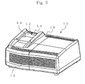
- Fig 2 shows the appearance of charging device 10.
- Fig 3 shows the appearance of battery pack 50.
- Fig 4 shows a battery-powered drill 70 driven by battery pack 50.
- battery pack 50 which is charged with charging device 10 will be explained with reference to Fig 3.
- a plurality of nickel-hydrogen batteries 58 electrically connected in series to each other are incorporated, as shown in Fig 1(A), into casing 51 made of a resin and molded to have an almost rectangular shape.
- the battery pack comprises a temperature sensor TM for detecting the temperature of batteries 58 and an EEPROM 61 storing data such as battery pack system and the like.
- the temperature sensor TM comprises a thermistor whose electric resistance changes depending on the temperature.
- fitting portions 52 forming fitting grooves 53 are formed parallel each other in a rail-like configuration on the upper end side of casing 51 of battery pack 50. They can be engaged with battery-powered drill 70 or charging device 10 when the battery pack is installed thereon. Further, a hook 54 that can be inserted or removed in the vertical direction is provided in a zone located at one end of fitting portions 52. Hook 54 is integrally molded with a lever 55 provided at the side surface of casing 51 and is impelled in the protrusion direction by a coil spring (not shown in the figures). As a result, when battery pack 50 is installed on battery-powered drill 70 or charging device 10, the hook can be engaged with the prescribed hook groove formed therein.
- the hook serves to prevent easy separation of battery pack 50 from battery-powered drill 70 or charging device 10. Furthermore, when lever 55 is pushed down toward the lower end of casing 55 against the impelling force of coil spring, hook 54 is moved toward the lower end so as to be retracted. Therefore, the engagement with the hook groove is released and battery pack 50 can be separated from battery-powered drill 70 or charging device 10.
- Vent opening 56 is formed in a position in which it can be linked to a ventilation opening 16 provided in charging device when battery pack 50 is installed on charging device 10.
- air can be passed through the battery pack 50 by a cooling fan incorporated in charging device 10, thereby making it possible to cool the battery pack 50 during charging.
- charging device 10 provides an air cooling system.
- a plus terminal T1 and a minus terminal T2 shown in Fig 1(A) are provided in plus terminal groove 57 and minus terminal groove 59, respectively.
- the configuration of those terminals t1 and T2 is such that they can be brought in contact with charging terminals or output terminals of the mating apparatus when battery pack 50 is installed on battery-powered drill 70 or charging device 10.
- Terminals T4, T5 for connecting the temperature sensor TM shown in Fig 1(A) and terminal T6 for connecting EEPROM 61 are provided inside a connector 60.
- the battery pack 50 having the above-described configuration is used by installing it on battery-powered drill 70, shown in Fig 4.
- a battery pack attachment 75 is formed in battery-powered drill 70 below a grip 74 that can be held by a user.
- a fitting portion that can be engaged with fitting portion 52 of battery pack 50 and the prescribed hoot groove that can be engaged with hook 54 of battery pack 50 are formed in battery pack attachment 75. Therefore, battery pack 50 can be detachably attached to battery pack attachment 75.
- battery-powered drill 70 having battery pack 50 thus installed thereon, the plus terminal T1 and minus terminal T2 of battery pack 50 are connected to charging terminals (not shown in the figures) at the side of battery-powered drill 70 to receive power supply.
- a chuck 76 can be rotated by a motor (not shown in the figures).
- the appearance of lithium ion battery pack 50B is identical to that of nickel-hydrogen battery pack 50 described above with reference to Fig 3 and the description thereof is omitted.
- charging device 10 for charging the battery pack 50 and battery pack 50B will be described below with reference to Fig 1(A) and Fig 2.
- charging device 10 has a resin casing 11.
- a fitting portion 12 on which the battery pack 50 can be installed or an air suction opening 13 through which the air supplied into battery pack 50 by the incorporated cooling fan can be sucked in from the outside is formed integrally with casing 11.
- various indicators (not shown in the figures), such as a capacity indication lamp for indicating the capacity of battery pack 50 during charging or a state indication lamp for indicating an operation state of charging device 10, are provided at casing 11 of charging device 10 and actuated and controlled by the below-described control circuit.
- a guide 14 which can guide the fitting groove 53 of battery pack 50 and a ventilation opening 16 that can be linked to vent opening 56 of battery pack 50 are formed in fitting portion 12, and the prescribed hook groove that can be engaged with hook of battery pack 50 is provided in the ventilation opening 16. Furthermore, output terminals t1, t2 that can be electrically connected to plus terminal T1 and minus terminal T2 of battery pack 50 are also provided in fitting portion 12, and a connector (not shown in the figures) that can be connected to connector 60 of battery pack 50 is also provided therein.
- the connector contains output terminal t3, t4 for power supply, a terminal t5 for connection to the temperature sensor TM of battery pack 50, and a communication terminal t6 for connection to EEPROM 61 of battery pack 50.
- a control circuit of charging device 10 is mainly composed of a first power source circuit 22A for charging the battery pack, a charge current control unit 24 for controlling the charge current, a control unit 26 that can constitute a detection unit for detecting the battery temperature (and voltage in the below-described case) and a current search unit for searching the charge current value, a voltage detection unit 27 comprising a pair of resistors, a resistor R1 for temperature detection, a memory unit 29, and a second power supply circuit 22B for supplying a constant voltage of 5 V.
- First power supply circuit 22A is set so as to have a capacity sufficient to charge batteries 58 of battery pack 50.
- First power supply circuit 22A and second power supply circuit 22B receive power supply from a transformer which steps down the voltage of a commercial power source (not shown in the figures), and first power supply circuit 22A adjusts the charging current to the batteries by changing the duty ratio.
- second power supply circuit 22B is designed to supply a constant voltage of 5 V, and 5 V potential can be output via the output terminals t3, t4.
- Output terminal t4 is connected to ground of second power supply circuit 22B.
- resistor R1 for temperature detection is connected in series with the temperature sensor TM whose resistance varies depending on the temperature, and a voltage of 5 V is supplied from the second power supply circuit 22B.
- Control unit 26 detects the battery temperature during charging from changes in the potential between resistor R1 for temperature detection and temperature sensor TM and also detects the voltage supplied to the battery from the changes in potential on the resistor of voltage detection unit 27 comprising a pair of resistors.
- memory unit 29 stores the current value control data such as the prescribed map.
- EEPROM 61 of nickel-hydrogen battery pack 50 stores the battery type (nickel-hydrogen battery) and the below-described target temperature rise pattern during charging.
- control unit 26 can determine the temperature rise value by differentiating the temperature values calculated based on the potential of resistor R1 for temperature detection, then calculate the prescribed current value based on the temperature rise pattern, and output this current value as a current command value to charging current control unit 24.
- Charging current control unit 24 controls the first power source circuit 22A based on the current command value from control unit 26 and adjusts the charging current of battery pack 50.
- lithium ion battery pack 50(B) comprises lithium ion batteries 58B, BEPROM 61, and a battery voltage transformation circuit 62 that can constitute an output unit detecting and outputting the potential of lithium ion batteries 58B.
- Battery voltage transformation circuit 62 as shown by a circuit diagram in Fig 5, is connected to terminals T1 T2 connected to the first power source circuit 22A shown in Fig 1 and lithium ion batteries 58B and also to terminal T3 to which a potential of 5 V is applied from the second power source circuit 22B, terminal T5 connected to control unit 26, and terminal T4 connected to ground of second power source circuit 22B.
- Voltage of the plus terminals of lithium ion batteries 58 and a potential of 5 V (terminal T3) from the second power source circuit 22B are applied to the non-inverter input i+ of operational amplifier OP of the battery voltage transformation circuit, while being divided between a 22 K ⁇ resistor and a 33 K ⁇ resistor. Furthermore, a potential of lithium ion batteries 58 is applied to the inverted input i-, while being divided between a 33 K ⁇ resistor and 3.3 K ⁇ resistor. Furthermore, a potential of 5 V (terminal T3) from the second power source circuit 22B is applied to a positive power source v+ of operational amplifier OP, and the ground potential (terminal T4) from the second power source circuit 22B is applied to the negative power source v-.
- the operational amplifier OP applies a voltage corresponding to the potential of lithium ion batteries 58B from the output terminal OT to control unit 26 of charging device 10 via terminal T5.
- a configuration was used in which a constant voltage of 5V was supplied from the charging device.
- a constant voltage source may also be provided in the lithium ion battery pack 50B.
- control unit 26 is such that when lithium ion batteries 58B are charged, it can determine the voltage rise value by differentiating the voltage values calculated based on the potential supplied from the battery voltage transformation circuit, then calculate the prescribed current value based on the below-described voltage rise pattern, and output the current value to charging current control unit 24 as a current command value. Then, charging current control unit 24 controls the first power source circuit 22A based on the current command value from control unit 26 and adjusts the charging current of battery pack 50B.
- control unit 26 controls the first power source circuit 22A and charging current control unit 24 according to the prescribed algorithm and charges nickel-hydrogen batteries 58 in battery pack 50 or lithium ion batteries 58B in lithium ion battery pack 508. If the capacity indication lamp indicating the capacity of battery pack 50 comes on during charging and charging is completed, the charging is terminated and the user is informed about it by the same lamp.
- the structure of control unit 26 is such that it can conduct a variety of operations such as charging.
- the charging time is shortened, but the temperature increase becomes significant. Conversely, if the charging current is decreased, the charging time is extended, but the temperature rise is reduced.
- a specific feature of nickel-hydrogen batteries is that the temperature gradient (temperature rise value) changes significantly depending on the charge current and the already charged capacity. For this reason, in the present embodiment, charging is conducted, while changing the current value in order to suppress the temperature rise.
- the state of batteries is determined based on the temperature rise value and charging is conducted by changing the current value according to the temperature rise in the battery, that is, the current that can flow, while the temperature rise in the battery is made constant.
- a battery temperature rise value is plotted against the ordinate and the charging time is plotted against the abscissa.
- Curve L in the figure represents the temperature rise values at charging completion corresponding to the charging time, those values being observed when charging was conducted so that the temperature rise value was constant.
- the charging time was 20 min
- the charging time was 30 min
- the charging time was 10 min
- the temperature rise value can be determined from the charging completion time and battery temperature rise value at the time of charging completion based on curve L. For example, it is clear that in order to complete charging in 20 min, charging may be conducted so as to obtain a temperature gradient (temperature rise value) shown by line (a) connecting 0 deg in the figure and 33 deg on curve L. In this case, charging is completed almost exactly in 20 min when the temperature becomes 53°C (temperature rise value 33 deg).
- Fig 6 also shows changes in the current value corresponding to a constant temperature rise value which are shown as the charging current.
- the value of charging current should be frequently adjusted.
- fine adjustment components are omitted.
- the current value in the first half of charging is relatively large, gradually decreasing in the second half of charging.
- a rapid decrease in charging current at the completion of charging indicates that charging of the nickel-hydrogen batteries was completed.
- charging is completed when this effect is detected.
- the so-called "overshoot" effect is sometimes observed in the nickel-hydrogen batteries.
- the temperature may rapidly increase because of the past charging history rather that owing to the present charging current.
- the temperature rise value cannot be made below the preset value even if the current value is decreased.
- charging is completed when this effect is detected.
- the current value is adjusted so as to obtain a constant temperature rise value
- the current value is adjusted so that the temperature rises according to the prescribed pattern in order to further shorten the charging time.
- a battery temperature rise value is plotted against the ordinate and the charging time is plotted against the abscissa.
- the area E shown by hatching represents the charging time and temperature rise value at the charging completion time.
- the temperature gradient shown by (a) in the figure was made constant so that the charging conducted with the charging device of the first embodiment was completed within 20 min, the temperature at charging completion was 33 deg.
- the charging could be completed at a battery temperature rise value of 30°C.
- area E shown by hatching represents the charging time and temperature rise value at charging completion obtained under various charging conditions.
- the boundary line B of area E represents the temperature rise value attained when charging was completed at the lowest temperature.
- broken line (a) shown in Fig 7 demonstrates that when the temperature rise value was made constant, as was explained with reference to Fig 6, the battery temperature rise value was 33 deg.
- solid line (d) solid line (d) in the figure. The reason why charging can be completed at the low temperature when the temperature rise value is controlled as peak-like rather than the temperature rise value is made constant lies as follows.
- the temperature rise pattern is set so that the difference of temperature between battery temperature and atmosphere temperature is small, battery is hardly cooled, capacity is nearly empty, temperature rise in charging is relatively small, temperature rise value in the first half period of charging is relatively high, contrary, the difference of temperature between battery temperature and atmosphere temperature is large, battery is easily cooled, temperature rise in charging is relatively large, temperature rise value in the remaining half period of charging is relatively low. That is, charging can be conducted so that the temperature at the time of charging completion is the lowest by optimizing the temperature rise pattern. In the present embodiment, based on the result of the above experiment, the current value is adjusted and charged based on the temperature rise pattern so that the charging can be competed at the lowest temperature.
- EEPROMs of a plurality of nickel-hydrogen battery packs 50 store respective data for determining the temperature rise patterns described above with reference to Fig 7.
- the temperature rise pattern differs significantly depending on the voltage of battery pack (number of cells), battery type (even some of nickel-hydrogen batteries can have different characteristics), heat emission ability of battery pack, and the like. Therefore, storing respective temperature rise patterns for a plurality of battery packs makes it possible to charge any battery pack with highest efficiency.
- Fig 8(A) illustrates the conventional method for charging of lithium ion batteries. If a voltage above the preset value VF is applied to a lithium ion battery, it can even cause inflammation of the battery. For this reason, charging is started at a constant current (constant current control) and when the voltage of the lithium ion battery increases and reaches the preset value VF (time t1), the constant-current control is switched to a constant-voltage control so as to retain the preset value VF and charging is continued till the current becomes no more than a preset value (time t2). Thus, in the conventional charging system, charging of lithium ion batteries required a constant-current control and a constant-voltage control.
- Fig 8(B) illustrates the lithium ion battery charging system of the present embodiment.
- the current value is controlled so as to obtain a voltage rise pattern shown in the figure.
- the charging device 10 charges the lithium ion battery pack 50 by switching the charging current, without using a constant-voltage circuit.
- Charging device 10 is a commercial product designed to conduct charging so that the temperature of nickel-hydrogen battery pack 50 is raised according to the temperature rise pattern described above with reference to Fig 7.
- charging of lithium ion batteries can be conducted without any modification of the charging device. Therefore, a battery voltage transformation circuit 62 is installed on the lithium ion battery pack 50B and charging is conducted by applying a voltage value corresponding to the voltage of the lithium ion battery 58B from the lithium ion battery pack 50B to the charging device.
- charging device 10 inputs temperature changes in the nickel-hydrogen battery pack 50 as a voltage value and controls the current so as to follow the temperature rise pattern.
- Such charging device charges the lithium ion battery pack 50B, it inputs voltage changes of the lithium ion battery (recognized as temperature changes by the charging device) as voltage values and controls the current so as to follow the voltage rise pattern (recognized as the temperature rise pattern by the charging device), thereby charging the lithium ion batteries in the same manner as nickel-hydrogen batteries.
- control unit 26 of charging device reads the contents of EEPROM 61 of nickel-hydrogen battery pack 50 (S12).
- Control unit 26 detects the temperature of battery pack 50 based on the voltage value determined by the voltage dividing resistance of thermistor TM and resistor R1 (S16). Then, the peak-like temperature rise pattern described above with reference to Fig 7 is calculated based on data read from EEPROM 61 of nickel-hydrogen battery pack 50 (S22).
- Control unit 26 detects a temperature gradient from the temperature rise pattern (S24), determines the temperature rise value by differentiating the difference between the previously detected temperature value and the temperature value that was input this time, and checks the current value by comparing the detected temperature rise value and the temperature rise pattern calculated in step 22 (S26) . When the temperature rise value is less than the gradient, the current value is increased above the present value. Conversely, when the gradient is less, the current value is decreased.
- the batteries are charged, while the current value is being adjusted so that the temperature rise value follows the temperature rise pattern. Therefore, charging can be conducted so that the temperature at the time of charging completion is the lowest temperature by optimizing the temperature rise pattern as described above with reference to Fig 7.
- control unit 26 of charging device reads the content of EEPROM 61 of lithium ion battery pack 50B (S12) .
- Control unit 26 detects the potential (recognized as the temperature by the control unit) based on the output voltage value from the battery voltage transformation circuit 62 incorporated in lithium ion battery pack 50B (S16) .
- a peak-like voltage rise pattern (produced as a temperature rise pattern in the control unit) described above with reference to Fig 8(B) is calculated based on the data read out from EEPROM 61 of lithium ion battery pack 50B (S22) .
- Control unit 26 detects the temperature gradient (voltage gradient) from the temperature rise pattern (voltage rise pattern) (S24), determines the temperature rise value (voltage rise value) by differentiating the difference between the previously detected temperature value (voltage value) and the temperature value (voltage value) that was input this time, and checks the current value by comparing the detected temperature rise value (voltage rise value) and the temperature rise pattern (voltage rise pattern) calculated in step 22 (S26). When the temperature rise value (voltage rise value) is less than the gradient, the current value is increased above the present value. Conversely, when the gradient is less, the current value is decreased.
- lithium ion batteries which require constant-voltage charging in the final period of charging can be charged with the existing charging device for nickel-hydrogen batteries and nickel-cadmium batteries, without any modification of the charging device.
- the charging system of the second embodiment will be described below.
- the mechanical structure of the charging device and battery pack of the second embodiment are identical to those of the above-described first embodiment.
- charging of a battery pack was conducted without recognizing whether it contains nickel-hydrogen batteries or lithium ion batteries.
- the charging device is programmed so as to conduct charging upon recognizing whether the batteries which are to be charged are nickel-hydrogen batteries or lithium ion batteries.
- correction of the program of the existing charging device makes it possible to conduct optimum charging of not only the nickel-hydrogen batteries, but also of lithium ion batteries.
- the charging device reads the contents of EEPROM 61 of battery pack 50 (S12). Then, the read-out content is used to determine whether the batteries which are to be charged are in a nickel-hydrogen battery pack 50 or in a lithium ion battery pack 50B (S14). In case of lithium ion batteries s (S14: Yes), the program proceeds to the below described charging of lithium ion batteries.
- control unit 26 detects the temperature of battery pack 50 based on the voltage value determined by the voltage dividing resistance of thermistor TM and resistor R1 (S16). Then, the peak-like temperature rise pattern described above with reference to Fig 7 is calculated based on data read from EEPROM 61 of nickel-hydrogen battery pack 50 (S22).
- Control unit 26 detects the temperature gradient from the temperature rise pattern (S24), determines the temperature rise value by differentiating the difference between the previously detected temperature value and the temperature value that was input this time, and checks the current value by comparing the detected temperature rise value and the temperature rise pattern calculated in step 22 (S26) . When the temperature rise value is less than the gradient, the current value is increased above the present value. Conversely, when the gradient is less, the current value is decreased.
- the batteries are charged, while the current value is being adjusted so that the temperature rise value follows the temperature rise pattern. Therefore, charging can be conducted so that the temperature at the time of charging completion is the lowest temperature by optimizing the temperature rise pattern as described above with reference to Fig 7.
- the charging device reads out the contents of EEPROM 61 of battery pack 50 as described above with reference to Fig 10 (S12). Then, if the battery which is being charged is determined to be a lithium ion battery based on the read-out contents (S14: Yes), the program proceeds to S116 shown in Fig 11.
- Control unit 26 detects the potential of battery pack 50 based on the output voltage value from the battery voltage transformation circuit 62 incorporated in the lithium ion battery pack 50B (S116). Control 26 determines the voltage gradient from the voltage rise pattern read out from battery pack 50B (S124), then the voltage rise value is determined by differentiating the difference between the previous detected voltage value and the presently input value, and the current value is checked by comparing the detected voltage rise value and the voltage rise pattern calculated in step 120 (S126). Here, when the voltage rise value is less than the voltage rise gradient, the current value is increased above the present value. Conversely, the gradient is lower, the current value is decreased.
- the set time for example, 10 min
- charging device 10 when charging device 10 charges nickel-hydrogen batteries, charging is conducted by adjusting the current value so that the temperature follows the target temperature rise pattern. Therefore, nickel-hydrogen batteries demonstrating a large increase in temperature can be charged within a short time so that a high temperature is not attained. Furthermore, when charging device 10 charges the lithium ion batteries 58B, charging is conducted by adjusting the current value so that the voltage follows the target voltage rise pattern. Thus, if the voltage of lithium ion battery pack 50B reaches the preset voltage VF, charging is continued, while reducing the electric current according to the voltage rise pattern shown in Fig 8(B) so as to maintain the preset voltage VF.
- lithium ion battery pack 50B can be charged safely without applying a voltage exceeding the preset voltage VF.
- the first batteries which can be charged at a constant current such as nickel-hydrogen batteries
- second batteries which can be charged only at a potential below the preset level such as lithium ion batteries
- the charging device charged the nickel-hydrogen batteries as the batteries which can be charged at a constant current.
- other batteries such nickel-cadmium batteries can be charged together with the nickel-hydrogen batteries or instead of them.
- lithium ion batteries were considered as the batteries which require constant-voltage charging in the final period of charging.
- various lithium batteries can be charged in the charging system of the first and second embodiments.
Landscapes
- Engineering & Computer Science (AREA)
- Power Engineering (AREA)
- Secondary Cells (AREA)
- Charge And Discharge Circuits For Batteries Or The Like (AREA)
Applications Claiming Priority (2)
| Application Number | Priority Date | Filing Date | Title |
|---|---|---|---|
| JP2000388415A JP3778262B2 (ja) | 2000-12-21 | 2000-12-21 | 充電方式及び電池パック |
| EP01129308A EP1217710B1 (fr) | 2000-12-21 | 2001-12-13 | Procédé de charge de batterie et bloc de batterie |
Related Parent Applications (1)
| Application Number | Title | Priority Date | Filing Date |
|---|---|---|---|
| EP01129308A Division EP1217710B1 (fr) | 2000-12-21 | 2001-12-13 | Procédé de charge de batterie et bloc de batterie |
Publications (2)
| Publication Number | Publication Date |
|---|---|
| EP1837976A2 true EP1837976A2 (fr) | 2007-09-26 |
| EP1837976A3 EP1837976A3 (fr) | 2007-12-12 |
Family
ID=18855155
Family Applications (4)
| Application Number | Title | Priority Date | Filing Date |
|---|---|---|---|
| EP07110412A Withdrawn EP1837976A3 (fr) | 2000-12-21 | 2001-12-13 | Système de chargement et bloc-batterie |
| EP01129308A Expired - Lifetime EP1217710B1 (fr) | 2000-12-21 | 2001-12-13 | Procédé de charge de batterie et bloc de batterie |
| EP07110408A Withdrawn EP1837974A3 (fr) | 2000-12-21 | 2001-12-13 | Système de chargement et bloc-batterie |
| EP07110411A Withdrawn EP1837975A3 (fr) | 2000-12-21 | 2001-12-13 | Système de chargement et bloc-batterie |
Family Applications After (3)
| Application Number | Title | Priority Date | Filing Date |
|---|---|---|---|
| EP01129308A Expired - Lifetime EP1217710B1 (fr) | 2000-12-21 | 2001-12-13 | Procédé de charge de batterie et bloc de batterie |
| EP07110408A Withdrawn EP1837974A3 (fr) | 2000-12-21 | 2001-12-13 | Système de chargement et bloc-batterie |
| EP07110411A Withdrawn EP1837975A3 (fr) | 2000-12-21 | 2001-12-13 | Système de chargement et bloc-batterie |
Country Status (4)
| Country | Link |
|---|---|
| US (1) | US6563290B2 (fr) |
| EP (4) | EP1837976A3 (fr) |
| JP (1) | JP3778262B2 (fr) |
| DE (1) | DE60142955D1 (fr) |
Families Citing this family (50)
| Publication number | Priority date | Publication date | Assignee | Title |
|---|---|---|---|---|
| JP3805664B2 (ja) | 2001-11-01 | 2006-08-02 | 株式会社マキタ | 電池パック |
| JP3706576B2 (ja) * | 2001-12-27 | 2005-10-12 | 三洋電機株式会社 | 電源装置 |
| DE10203512B4 (de) * | 2002-01-30 | 2021-09-02 | Robert Bosch Gmbh | Handwerkzeugmaschine mit einem elektrischen Antrieb, einem Schaltmittel und einer Batterieeinheit |
| US7299063B2 (en) * | 2002-07-01 | 2007-11-20 | Sony Corporation | Wireless communication system, wireless communication device and wireless communication method, and computer program |
| US8471532B2 (en) | 2002-11-22 | 2013-06-25 | Milwaukee Electric Tool Corporation | Battery pack |
| US7425816B2 (en) | 2002-11-22 | 2008-09-16 | Milwaukee Electric Tool Corporation | Method and system for pulse charging of a lithium-based battery |
| US7714538B2 (en) | 2002-11-22 | 2010-05-11 | Milwaukee Electric Tool Corporation | Battery pack |
| US7589500B2 (en) | 2002-11-22 | 2009-09-15 | Milwaukee Electric Tool Corporation | Method and system for battery protection |
| US7157882B2 (en) | 2002-11-22 | 2007-01-02 | Milwaukee Electric Tool Corporation | Method and system for battery protection employing a selectively-actuated switch |
| US7176654B2 (en) * | 2002-11-22 | 2007-02-13 | Milwaukee Electric Tool Corporation | Method and system of charging multi-cell lithium-based batteries |
| US7253585B2 (en) | 2002-11-22 | 2007-08-07 | Milwaukee Electric Tool Corporation | Battery pack |
| DE10354871A1 (de) | 2002-11-22 | 2004-10-28 | Milwaukee Electric Tool Corp., Brookfield | Verfahren und System für den Schutz einer Batterie |
| US7140546B1 (en) * | 2002-12-12 | 2006-11-28 | Symbol Technologies, Inc. | Battery pack with integrated human interface devices |
| JP3936286B2 (ja) * | 2002-12-24 | 2007-06-27 | 株式会社マキタ | 充電装置及び充電方法 |
| JP3983681B2 (ja) * | 2003-01-14 | 2007-09-26 | 株式会社マキタ | 充電装置 |
| JP4269769B2 (ja) * | 2003-05-07 | 2009-05-27 | ソニー株式会社 | バッテリパック及び電子機器 |
| DE10327005B4 (de) * | 2003-06-12 | 2007-01-18 | Ernst U. Willy Niegeloh Gmbh & Co. Kg | Hornhauthobel |
| US7701172B2 (en) * | 2003-10-14 | 2010-04-20 | Black & Decker Inc. | Power driver and charger with flexible mounting system for battery pack |
| US20050077873A1 (en) * | 2003-10-14 | 2005-04-14 | Watson James B. | Power driver and charger with flexible mounting system for battery pack |
| DE102004030037B4 (de) * | 2003-11-19 | 2012-01-12 | Milwaukee Electric Tool Corp. | Akkumulator |
| FR2862558B1 (fr) * | 2003-11-20 | 2006-04-28 | Pellenc Sa | Outil portatif electrique autonome de puissance |
| JP2005160233A (ja) * | 2003-11-26 | 2005-06-16 | Makita Corp | 組電池及び電池パック |
| TWM250446U (en) | 2004-02-02 | 2004-11-11 | High Tech Comp Corp | Cradle of hand-held electronic device with heat dissipation effect |
| US7339353B1 (en) | 2004-03-10 | 2008-03-04 | Quallion Llc | Power system for managing power from multiple power sources |
| JP4278622B2 (ja) * | 2004-03-18 | 2009-06-17 | 三洋電機株式会社 | 電源装置 |
| EP1580863B1 (fr) * | 2004-03-26 | 2016-11-23 | HTC Corporation | Berceau pour dispositif électronique portatif avec capacité thermodissipatrice ameliorée |
| JP2005295750A (ja) * | 2004-04-02 | 2005-10-20 | Hitachi Koki Co Ltd | コードレス電動工具用充電器 |
| US20050275378A1 (en) * | 2004-06-14 | 2005-12-15 | Serafino Canino | Apparatus and method for illuminated battery charging device |
| US9192772B1 (en) | 2004-06-29 | 2015-11-24 | Quallion Llc | Portable medical power system |
| CN2762964Y (zh) * | 2005-01-10 | 2006-03-08 | 南京德朔实业有限公司 | 用电池供电的电动工具 |
| JPWO2007094334A1 (ja) | 2006-02-16 | 2009-07-09 | 京セラ株式会社 | 電力供給装置及び携帯電子機器 |
| US7615969B2 (en) * | 2006-07-27 | 2009-11-10 | Dell Products L.P. | Systems and methods for temperature-dependent battery charging |
| JP5262027B2 (ja) * | 2007-09-07 | 2013-08-14 | パナソニック株式会社 | 組電池、及び電池システム |
| US8089250B2 (en) * | 2008-09-16 | 2012-01-03 | Mitac Technology Corp. | Method and device for protecting battery of electronic device from overheating |
| EP2352216B1 (fr) * | 2008-11-20 | 2014-03-19 | Mitsubishi Electric Corporation | Convertisseur de courant |
| US8754614B2 (en) * | 2009-07-17 | 2014-06-17 | Tesla Motors, Inc. | Fast charging of battery using adjustable voltage control |
| US8552693B2 (en) * | 2009-07-17 | 2013-10-08 | Tesla Motors, Inc. | Low temperature charging of Li-ion cells |
| JP5523905B2 (ja) * | 2010-04-13 | 2014-06-18 | 株式会社マキタ | 端子接続構造 |
| US8235552B1 (en) | 2011-02-25 | 2012-08-07 | Makita Corporation | Cordless flashlight and radio device |
| US20130164567A1 (en) | 2011-06-24 | 2013-06-27 | Seektech, Inc. | Modular battery pack apparatus, systems, and methods |
| US10090498B2 (en) | 2012-06-24 | 2018-10-02 | SeeScan, Inc. | Modular battery pack apparatus, systems, and methods including viral data and/or code transfer |
| RU2635349C2 (ru) * | 2013-09-26 | 2017-11-13 | Ниссан Мотор Ко., Лтд. | Беспроводная система подачи электрической мощности и устройство передачи электрической мощности |
| JP2015154593A (ja) * | 2014-02-14 | 2015-08-24 | ソニー株式会社 | 充放電制御装置、電池パック、電子機器、電動車両および充放電制御方法 |
| JP6434798B2 (ja) * | 2014-12-11 | 2018-12-05 | 株式会社Subaru | 電力供給ユニット |
| US9917457B2 (en) | 2015-02-02 | 2018-03-13 | Black & Decker Inc. | Power tool with USB connection |
| EP3068010A1 (fr) * | 2015-03-10 | 2016-09-14 | HILTI Aktiengesellschaft | Chargeur de batterie pouvant fonctionner en réseau et système de recharge |
| US10950912B2 (en) | 2017-06-14 | 2021-03-16 | Milwaukee Electric Tool Corporation | Arrangements for inhibiting intrusion into battery pack electrical components |
| CN108736082B (zh) * | 2018-05-22 | 2021-04-27 | 海能达通信股份有限公司 | 提高终端电池续航能力的方法、装置、设备及存储介质 |
| JP7123772B2 (ja) * | 2018-11-30 | 2022-08-23 | 株式会社マキタ | 充電器 |
| CN113489090B (zh) * | 2021-06-25 | 2023-07-21 | 广汽本田汽车有限公司 | 电池充电的控制系统、方法、装置和存储介质 |
Citations (1)
| Publication number | Priority date | Publication date | Assignee | Title |
|---|---|---|---|---|
| US5744937A (en) * | 1995-10-12 | 1998-04-28 | Samsung Electronics Co., Ltd. | Dual battery charging device for charging nickel metal-hydride and lithium-ion batteries |
Family Cites Families (14)
| Publication number | Priority date | Publication date | Assignee | Title |
|---|---|---|---|---|
| DE4200693C1 (fr) | 1992-01-14 | 1993-05-06 | Robert Bosch Gmbh, 7000 Stuttgart, De | |
| US5371453A (en) * | 1993-01-28 | 1994-12-06 | Motorola, Inc. | Battery charger system with common charge and data exchange port |
| JPH0785893A (ja) | 1993-09-17 | 1995-03-31 | Sony Corp | 電池充電方法 |
| JP2732204B2 (ja) * | 1993-09-29 | 1998-03-25 | 株式会社ジップチャージ | 二次電池の高速充電方法及びその装置 |
| US5582928A (en) * | 1994-12-30 | 1996-12-10 | Texas Instruments Incorporated | Supply batteries |
| US5518832A (en) * | 1995-01-09 | 1996-05-21 | Motorola, Inc. | Apparatus for simulating high battery temperature used in recharging lithium ion cells |
| JP3234760B2 (ja) * | 1995-11-30 | 2001-12-04 | 松下電器産業株式会社 | 携帯電話装置 |
| US5764030A (en) * | 1997-03-14 | 1998-06-09 | International Components Corporation | Microcontrolled battery charger |
| JP4314641B2 (ja) * | 1997-11-25 | 2009-08-19 | パナソニック電工株式会社 | 充電装置 |
| US6455186B1 (en) * | 1998-03-05 | 2002-09-24 | Black & Decker Inc. | Battery cooling system |
| US5986430A (en) * | 1998-07-06 | 1999-11-16 | Motorola, Inc. | Method for ultra-rapidly charging a rechargeable battery using multi-mode regulation in a vehicular recharging system |
| SE522234C2 (sv) * | 1998-08-25 | 2004-01-27 | Ericsson Telefon Ab L M | Sätt och anordning avseende temperaturavkänning i elektriska kretsar |
| JP3495637B2 (ja) | 1999-03-26 | 2004-02-09 | 株式会社マキタ | 充電装置及び充電方式 |
| US6040683A (en) * | 1999-05-28 | 2000-03-21 | Motorola, Inc. | Battery charger with active feedback voltage controller |
-
2000
- 2000-12-21 JP JP2000388415A patent/JP3778262B2/ja not_active Expired - Lifetime
-
2001
- 2001-12-13 EP EP07110412A patent/EP1837976A3/fr not_active Withdrawn
- 2001-12-13 EP EP01129308A patent/EP1217710B1/fr not_active Expired - Lifetime
- 2001-12-13 DE DE60142955T patent/DE60142955D1/de not_active Expired - Lifetime
- 2001-12-13 EP EP07110408A patent/EP1837974A3/fr not_active Withdrawn
- 2001-12-13 EP EP07110411A patent/EP1837975A3/fr not_active Withdrawn
- 2001-12-18 US US10/025,419 patent/US6563290B2/en not_active Expired - Lifetime
Patent Citations (1)
| Publication number | Priority date | Publication date | Assignee | Title |
|---|---|---|---|---|
| US5744937A (en) * | 1995-10-12 | 1998-04-28 | Samsung Electronics Co., Ltd. | Dual battery charging device for charging nickel metal-hydride and lithium-ion batteries |
Also Published As
| Publication number | Publication date |
|---|---|
| EP1217710B1 (fr) | 2010-09-01 |
| JP2002191135A (ja) | 2002-07-05 |
| EP1837975A2 (fr) | 2007-09-26 |
| EP1837975A3 (fr) | 2007-12-12 |
| EP1837974A3 (fr) | 2007-12-12 |
| EP1217710A1 (fr) | 2002-06-26 |
| EP1837974A2 (fr) | 2007-09-26 |
| US20020079867A1 (en) | 2002-06-27 |
| EP1837976A3 (fr) | 2007-12-12 |
| JP3778262B2 (ja) | 2006-05-24 |
| DE60142955D1 (de) | 2010-10-14 |
| US6563290B2 (en) | 2003-05-13 |
Similar Documents
| Publication | Publication Date | Title |
|---|---|---|
| EP1217710B1 (fr) | Procédé de charge de batterie et bloc de batterie | |
| US5818197A (en) | Adaptive battery charger with universal interface plate | |
| USRE39691E1 (en) | Battery charger and battery charging method | |
| US6603288B2 (en) | Battery chargers and charging methods | |
| CN101272059B (zh) | 对于多个电源中选定的一个电源可进行操作的电池充电器 | |
| US6504341B2 (en) | Method and apparatus for identifying and charging batteries | |
| US7656130B2 (en) | Battery charger | |
| US6476584B2 (en) | Battery charger and battery charging method | |
| EP1710889A2 (fr) | Chargeur de batterie pour une batterie aux ions de lithium | |
| US7106027B2 (en) | Battery changers | |
| US6225786B1 (en) | Battery charger | |
| JP2010522533A (ja) | 電池検出を備える超高速電池充電器 | |
| JP3638483B2 (ja) | 充電装置及び充電方式 | |
| JP2010011594A (ja) | 充電回路 | |
| EP1338074B1 (fr) | Limitation de temperature dans la charge de batterie au lithium | |
| EP0747986B1 (fr) | Procede et appareil permettant de juger qu'un element d'accumulateur est branche a un chargeur | |
| JP2006286508A (ja) | リチウム電池パックおよびリチウム電池用充電装置 | |
| JP3705987B2 (ja) | 充電装置、アダプタ及び二次電池 | |
| JPH06113471A (ja) | 充電装置 | |
| JP3842076B2 (ja) | 充電装置 | |
| JP2002374635A (ja) | 充電装置 | |
| JP2001238361A (ja) | アダプタ |
Legal Events
| Date | Code | Title | Description |
|---|---|---|---|
| PUAI | Public reference made under article 153(3) epc to a published international application that has entered the european phase |
Free format text: ORIGINAL CODE: 0009012 |
|
| AC | Divisional application: reference to earlier application |
Ref document number: 1217710 Country of ref document: EP Kind code of ref document: P |
|
| AK | Designated contracting states |
Kind code of ref document: A2 Designated state(s): DE FR GB |
|
| PUAL | Search report despatched |
Free format text: ORIGINAL CODE: 0009013 |
|
| AK | Designated contracting states |
Kind code of ref document: A3 Designated state(s): DE FR GB |
|
| 17P | Request for examination filed |
Effective date: 20080509 |
|
| AKX | Designation fees paid |
Designated state(s): DE FR GB |
|
| 17Q | First examination report despatched |
Effective date: 20170302 |
|
| STAA | Information on the status of an ep patent application or granted ep patent |
Free format text: STATUS: THE APPLICATION HAS BEEN WITHDRAWN |
|
| 18W | Application withdrawn |
Effective date: 20170330 |